Electrical 3D Design & Documentation
|
|
|
- Abel Malone
- 6 years ago
- Views:
Transcription
1 Electrical 3D Design & Documentation Page 1 Overview Conventions User Tasks Using Electrical 3D Design & Documentation Entering the Electrical Assembly Design Workbench Entering the Electrical Part Design Workbench Defining Electrical Devices Defining an Equipment Defining an Electrical Connector Defining Electrical Connection Points Defining a Cavity Defining a Termination Defining a Connector Connection Point Defining a Bundle Connection Point Defining a Cavity Connection Point Creating Supports Connecting/Disconnecting Devices Connecting Electrical Devices Disconnecting Electrical Devices Using Catalogs Connecting Devices by Drag & Drop at Placement Using Smart Placement from Catalog Creating a Geometrical Bundle Creating a Bundle Segment Document Defining the Segment Parameters Defining the Segment Route Constraints Creating an Electrical Bundle Selecting External Data Systems Routing Wires from External Data Managing Links from External Data Viewing Related Objects Defining the Harness Flattening Parameters Extracting Data Flattening the Harness Rotating Bundle Segments Rotating Bundle Segments whatever the Selected Plan Bending Bundle Segments Scaling Bundle Segments Synchronizing the Environment Generating the HTML Report during the Synchronization
2 Using the Drawing Capabilities Customizing a Drawing View Generating a Drawing Creating Wire Annotations Creating Intra-Technological Feature Dimensions Creating Text Templates Storing Text Templates in a Catalog Annotating Drawings Using Text Templates Defining the Report Format Generating a Report Workbench Description Assembly Toolbars Part Toolbars Customizing General Harness Flattening Harness Management Wire Routing Electrical Process Interfacing Part Infrastructure Drafting Glossary Index Page 2
3 Overview Page 3 Welcome to the Electrical 3D Design and Documentation User's Guide! This guide is intended for users who need to become quickly familiar with the product. This overview provides the following information: Electrical 3D Design & Documentation in a Nutshell Before Reading this Guide Getting the Most Out of this Guide Accessing Sample Documents Conventions Used in this Guide Electrical 3D Design & Documentation in a Nutshell Electrical 3D Design & Documentation is a product which provides machinery and consumer goods industry with a dedicated toolset for designing and documenting their electrical systems. provides a set of tools for defining, placing and connecting them. It also allows the creation and management of wire and electrical device catalogs. This product offers the following main functions: electrical devices on parts and assemblies definition geometrical and electrical bundle creation assisted device placement according to the electrical specifications coming from external, legacy or CATIA electrical specification tool wire routing harness flattening capabilities. Before Reading this Guide Before reading this guide, you should be familiar with basic Version 5 concepts such as document windows, standard and view toolbars. Therefore, we recommend that you read the Infrastructure User's Guide that describes generic capabilities common to all Version 5 products. It also describes the general layout of V5 and the interoperability between workbenches. Getting the Most Out of this Guide
4 Page 4 To get the most out of this guide, we suggest that you start reading the User Tasks section, which deals with handling all the product functions. The Workbench Description section, which describes the Electrical 3D Design & Documentation workbench, and the Customizing section, which explains how to set up the options, will also certainly prove useful. Navigating in the Split View mode is recommended. This mode offers a framed layout allowing direct access from the table of contents to the information. Accessing Sample Documents To perform the scenarios, sample documents are provided all along this documentation. For more information about this, refer to Accessing Sample Documents in the Infrastructure User's Guide. Conventions Used in this Guide To learn more about the conventions used in the documentation, refer to the Conventions section.
5 Conventions Page 5 Certain conventions are used in CATIA, ENOVIA & DELMIA documentation to help you recognize and understand important concepts and specifications. Graphic Conventions The three categories of graphic conventions used are as follows: Graphic conventions structuring the tasks Graphic conventions indicating the configuration required Graphic conventions used in the table of contents Graphic Conventions Structuring the Tasks Graphic conventions structuring the tasks are denoted as follows: This icon... Identifies... estimated time to accomplish a task a target of a task the prerequisites the start of the scenario a tip a warning information basic concepts methodology reference information information regarding settings, customization, etc. the end of a task functionalities that are new or enhanced with this Release. allows you to switch back the full-window viewing mode. Graphic Conventions Indicating the Configuration Required Graphic conventions indicating the configuration required are denoted as follows:
6 Page 6 This icon... Indicates functions that are... specific to the P1 configuration specific to the P2 configuration specific to the P3 configuration Graphic Conventions Used in the Table of Contents Graphic conventions used in the table of contents are denoted as follows: This icon... Gives access to... Site Map Split View mode What's New? Overview Getting Started Basic Tasks User Tasks or the Advanced Tasks Workbench Description Customizing Reference Methodology Glossary Index Text Conventions The following text conventions are used: The titles of CATIA, ENOVIA and DELMIA documents appear in this manner throughout the text. File -> New identifies the commands to be used. Enhancements are identified by a blue-colored background on the text. How to Use the Mouse The use of the mouse differs according to the type of action you need to perform.
7 Use this mouse button... Whenever you read... Page 7 Select (menus, commands, geometry in graphics area,...) Click (icons, dialog box buttons, tabs, selection of a location in the document window,...) Double-click Shift-click Ctrl-click Check (check boxes) Drag Drag and drop (icons onto objects, objects onto objects) Drag Move Right-click (to select contextual menu)
8 User Tasks Page 8 The User Tasks section explains and illustrates how to create various kinds of features. The table below lists the information you will find. Using Electrical 3D Design & Documentation Defining Electrical Devices Defining Electrical Connection Points Creating Supports Connecting/Disconnecting Devices Using Catalogs Creating a Geometrical Bundle Creating a Bundle Segment Document Creating an Electrical Bundle Selecting External Data Systems Routing Wires from External Data Managing Links from External Data Viewing Related Objects Defining the Harness Flattening Parameters Extracting Data Flattening the Harness Rotating Bundle Segments Scaling Bundle Segments Synchronizing the Environment Using the Drawing Capabilities Defining the Report Format Generating a Report
9 Using Electrical 3D Design & Documentation Page 9 This task explains how to set up the environment to work with CATIA - Electrical 3D Design & Documentation. CATIA - Electrical 3D Design & Documentation includes two workbenches: Electrical 3D Design Assembly workbench to work at the level of an assembly of electrical objects. Electrical 3D Design Part workbench to add electrical behavior at the level of a part.
10 Entering the Electrical 3D Design Assembly Workbench Page 10 The Electrical 3D Design Assembly workbench allows you to create electrical assemblies in CATProduct documents. CATIA V5 is launched. A CATProduct document is displayed. 1. Choose the Electrical 3D Design Assembly item from the Start -> Equipments & Systems menu. The Electrical 3D Design Assembly workbench is displayed and ready to use.

11 Using the Electrical 3D Design Part Workbench Page 11 The Electrical 3D Design Part workbench is used to define electrical connectors or to convert standard parts into electrical devices. CATIA V5 is launched. A CATPart document is displayed. 1. Choose the Electrical 3D Design Part item from the Start -> Equipments & Systems menu. The Electrical 3D Design Part workbench is displayed with a CATPart document.
12 Defining Electrical Devices Page 12 These functionalities are available in both the Electrical Assembly and Part workbenches. They are used to add an electrical behavior to a product or a part. As a result, the product itself, the instance or the reference becomes an electrical element: When you open a CATPart document and you add an electrical behavior to the part, it is the reference which will be modified. If you insert this part in an assembly, all the occurrences will be modified. When you open a CATProduct document containing a CATPart, if you double-click to activate the product of the part or the part, and add an electrical behavior to it, the result is similar: you have modified the reference and all the occurrences will have an electrical behavior. As a consequence, you will have to save the part. On the other hand, if the root product is activated and you select the product of the part, it is only this instance of the part which will become an electrical device. The reference is NOT modified. This rule applies for all the devices. Equipment: Click this button and select the part or product to be converted into an equipment. Connector: Click this button and select the part or product to be converted into a connector.

13 Defining an Equipment Page 13 This task explains how to add an electrical behavior to a standard part. An equipment is an electrical device with one or more associated connectors placed into cavities. Let's see two different cases to illustrate: first, you will work with an instance of the product, i.e. only this instance will get the electrical behavior. If you insert the part to another assembly, it remains a standard part. then, you'll work with the reference of the part, i.e. all the instances of the part will get the electrical behavior. Adding the electrical behavior to an instance... The CATProduct document contains standard parts, which do not have electrical behavior. 1. Click the Define Equipment button. You are prompted to select a part or a product. 2. Click the equipment either in the specification tree or in the geometry. The Define Equipment Part dialog box opens: 3. Enter/change the name in the Instance name field if necessary. 4. Click OK to validate. The specification tree is updated. The part is not modified. The equipment is now an electrical object as the electrical behavior has been added to this instance.

14 Page 14 Adding the electrical behavior to the reference... Now if you open the CATPart document or, if you double-click to activate the PartForEquipment document in the example shown below, you will modify the reference document. 1. Click the Define Equipment button. You are prompted to select a part or a product. 2. Click the equipment (here PartForEquipment) either in the specification tree or in the geometry. The Equipment Part Definition dialog box opens: Note that it is the Part Number, which is displayed for edition. 3. Change the name in the Part Number field if necessary. 4. Click OK to validate. The specification tree is updated. The part has been modified. The equipment is now an electrical object as the electrical behavior has been added to this reference.

15 Page 15 An equipment allows bundle connection points, cavities as well as single insert connectors connected into cavities through a cavity connection point.

16 Defining an Electrical Connector Page 16 This task explains how to add an electrical behavior to a standard part to turn it into an electrical connector. You can add an electrical behavior to an instance or a reference. Refer to Defining an Equipment. The CATProduct document contains standard parts, which do not have electrical behavior. 1. Click the Define Connector button. You are prompted to select a part or a product. 2. Click the connector either in the specification tree or in the geometry. The Define Connector dialog box opens: The only type available is Single Insert Connector: male or female connector. 3. Change the name in the Instance name field if necessary. 4. Enter the Number of termination to be defined onto the connector. The electrical terminations are used to connect wires. 5. Click OK to validate. The specification tree is updated. The part is not modified. The instance of the connector is now an electrical object as the electrical behavior has been added.
17 Page 17 A single insert connector allows one connector connection point, bundle connection points and terminations.
18 Defining Electrical Connection Points Page 18 The connection functionalities are available in both the Electrical Assembly and Part workbenches. Cavity: Click this button and select the equipment where you want to define a cavity. Termination: Click this button and select the device where you want to define a termination. Bundle Connection Point: Click this button and set the placement constraints for the connection point between connectors and bundle segments. Connector Connection Point: Click this button and set the placement constraints for the connection point between connectors. Cavity Connection Point: Click this button and set the placement constraints for the connection point between cavities and equipments. It is possible to delete the electrical cavities, terminations and the connection points. This applies to: termination cavity cavity connection point connector connection point bundle connection point. Note that when deleting these objects, the associated publications are also deleted. But the publications of the geometries which constrain their placement are NOT automatically deleted, since they may have been created earlier, from another application. According to your choice, you can delete them using the publication management available in the Assembly Design workbench (Tools -> Publication menu item).
19 Defining a Cavity Page 19 This task explains how to define a cavity on an electrical device. The cavity is used to specify the location of the electrical object when connecting. Open any document containing an equipment where you want to place a cavity. 1. Click the Define Cavity button. The Cavity Definition dialog box opens: 2. Select the equipment where you want the cavity to be defined. 3. Change/enter a value in the IdNumber field. Note that the IdNumber must be unique. 4. Select a Representation, for example a pocket, a pad, a face Optionally, place a Contact constraint, for example a surface or a point. 6. Optionally, place a Coincidence constraint, for example a surface, a line or an axis. 7. Optionally, place an Orientation constraint, for example a surface, a line or an axis. The orientation is used to constrain the rotation i.e. the third degree of liberty. 8. Click OK to validate. The specification tree is updated.
20 Page 20 For more information about the placement constraints, refer to Using Assembly Constraints. A cavity is allowed on equipments.

21 Defining a Termination Page 21 This task explains how to define a termination on a connector. The termination is indissociable from the electrical component and corresponds to a contact crimped into a cavity. Open any document containing a connector where you want to place a termination. 1. Click the Define Termination button. 2. Select the electrical device where you want the termination to be defined. The Termination Definition dialog box opens: 3. Change/enter a value in the IdNumber field. Note that the IdNumber must be unique. 4. Optionally select a Representation, for example a pocket, a pad, a face Click OK to validate. The specification tree is updated.
22 Page 22 A termination is allowed on connectors.
23 Defining a Connector Connection Point Page 23 This task explains how to define a connector connection point on a connector. The connector connection point is used to specify how the mating connectors are placed when connecting. Open any document containing a single insert connector where you want to place a connector connection point. 1. Click the Define Connector Connection Point button. 2. Select the electrical device where you want the connector connection point to be defined. The Connector Connection Point Definition dialog box opens: 3. Change/enter a value in the Name field. 4. Select a Representation, for example a pocket, a pad, a face Optionally, place a Contact constraint, for example a surface or a point. 6. Optionally, place a Coincidence constraint, for example a surface, a line or an axis. 7. Optionally, place an Orientation constraint, for example a surface, a line or an axis. The orientation is used to constrain the rotation i.e. the third degree of liberty. 8. Click OK to validate. The specification tree is updated.

24 Page 24 For more information about the placement constraints, refer to Using Assembly Constraints. A connector connection point is only allowed on single insert connectors.

25 Defining a Bundle Connection Point Page 25 This task explains how to define a bundle connection point on a device. The bundle connection point is used to specify the position and the direction of the bundle segment connected to the connector or the equipment. Open any document containing a connector where you want to place a bundle connection point. 1. Click the Define Bundle Connection Point button. 2. Select the connector or equipment where you want the bundle connection point to be defined. The Bundle Connection Point Definition dialog box opens: 3. Change/enter a value in the Name field. 4. Select a Representation, for example a surface or a point. 5. Set a Point constraint: select a point. This point will possibly be used as bundle segment extremity. 6. Set a Initial Condition constraint: select a plane or an axis. This plane or axis will possibly be used to orientate the bundle segment. 7. Click OK to validate. The specification tree is updated.
26 Page 26 A bundle connection point is allowed on equipments and connectors.

27 Defining a Cavity Connection Point Page 27 This task explains how to define a cavity connection point on an equipment. The cavity connection point is used to specify how the connector is placed in the cavity when connecting. Open any document containing an equipment and a connector, where you want to place a cavity connection point. 1. Click the Define Cavity Connection Point button. 2. Select the connector where you want the cavity connection point to be defined. The Cavity Connection Point Definition dialog box opens: 3. Change/enter a value in the Name field. 4. Select a Representation, for example a pocket, a pad, a face. 5. Optionally, set a Contact constraint, for example a surface or a point. 6. Optionally, set a Coincidence constraint, for example a surface, a line or an axis. 7. Optionally, set an Orientation constraint, for example a surface, a line or an axis. The orientation is used to constrain the rotation i.e. the third degree of liberty. 8. Click OK to validate. The specification tree is updated.

28 Page 28 For more information about the placement constraints, refer to Using Assembly Constraints. A cavity connection point is allowed on connectors.
. 1. Click the Define Support button.")
29 Creating Supports Page 29 This task explains how to define a support for electrical bundle segments. This functionality is available in Electrical Part Design workbench only. A support is a mechanical object used to hold the bundle segments in position. Open any document containing a standard part (with no electrical behavior). 1. Click the Define Support button. You are prompted to select a part. 2. Click the Support either in the specification tree or in the geometry. The Support Definition dialog box opens: 3. Enter/change the name for the support. 4. Select the point through the support, to define the reference position of the bundle segment in the support.


30 Page 30 If the point is not already defined, click the button. For more information, refer to the Point Definition. You are prompted to select the first plane: the way in of the support. 5. Select the front face. You are prompted to select a second plane: the way out of the support. 6. Select the opposite face. To be selectable, it must be parallel to the first face. 7. Click OK to validate. The specification tree is updated: two extra planes have been defined (Plane.1 and Plane.2).
31 Connecting/Disconnecting Electrical Devices Page 31 These functionalities are only available in the Electrical Assembly workbench. Connecting: Click this button and select the devices you want to connect. Disconnecting: Click this button and select the devices you want to disconnect.
32 Connecting Electrical Devices Page 32 This task explains how to connect the electrical devices. When you create an electrical connection between two devices: an electrical link is created between the connected components. See Related Objects. if placement constraints have been defined on connection points, the mechanical assembly constraints are automatically created. Since it's possible to use this command in visualization mode (with the cache activated), the scenario is described according to the two modes: The design mode is mandatory to perform the connections. In visualization mode, the model is lighter since the geometry is not loaded. It allows you to display large assemblies. When you work in visualization mode, CATIA switches to the design mode only for the elements which contribute to the connection. In Design Mode If you open the document in design mode (the cache is not activated), the whole geometry is loaded. 1. Click the Connect Electrical Devices button to connect two devices. You are prompted to select the first device. it's the first selected object that moves to the second one's location an electrical connection has been created as well as mechanical constraints. 2. Select the first device either in the geometry or in the specification tree:


33 Page 33 You are prompted to select another device. 3. Move the cursor onto the second device before selecting it, as shown below: The cavity connection point of the first device and the cavities of the second one are displayed in green: this means that it is possible to connect the connector into the cavity of the equipment. According to the selection, if a cavity is already used or if no connection point is defined on the equipment, it is displayed in red.

34 Page Click to select a connection point available on the equipment, Cavity1 for example. The devices are connected together and the mechanical constraints are added to the specification tree: Note that you can select the second connection point using one of the three following ways to get the same result: the representation of the connection point in the geometry the label with the name of the connection point the connection point in the specification tree. In Visualization Mode If you open the document in visualization mode (the cache is activated), the geometry is not loaded.

35 Page Select the Connect Electrical Devices button to connect two devices. You are prompted to select the first device. it's the first selected object that moves to the second one's location an electrical connection has been created together with mechanical constraints. 2. Select the first device either in the geometry or in the specification tree. You are prompted to select the second device. 3. Move the cursor onto the second device before selecting it, as shown below: Note that: You cannot expand the specification tree since you are in visualization mode. No annotations are displayed on the device connection points. 4. Click to select the equipment: The geometry is loaded for both devices and the annotations display:


36 Page Click to select a connection point available on the device, for example Cavity1. The devices are connected together and the mechanical constraints are added to the specification tree:
37 Page 37 Note that the specification tree also displays the plus sign for the other devices: this is due to the update, which loads the publications. However the geometry for these components is not loaded, as shown in the picture below:

38 Disconnecting Electrical Devices Page 38 This task explains how to disconnect electrical devices. 1. Select the Disconnect Electrical Devices button to disconnect devices. You are prompted to select the first device. 2. Select the first device you want to disconnect: You are prompted to select another device. 3. Select the second device that was connected to the first one:
39 Page 39 The devices are disconnected. The electrical connection is deleted. The mechanical constraints are deleted in the geometry and the specification tree: Note that the device position remains unchanged but as the mechanical constraints have been deleted, you can shift the connectors using the compass.
40 Using Catalogs Page 40 These functionalities are available in the Electrical Assembly workbench. The first one is also available in the Electrical Part workbench. Connecting Devices: Drag and drop the device from the catalog at its proper placing. Using Smart Placement: Select the component, point to the correct position and click to place it.

41 Connecting Devices by Drag and Drop at Placement Page 41 This task explains how to place devices by drag and drop with automatic connection to an existing component. Open a new product document. 1. Click the Catalog Browser button to open the ElecIntegration.catalog. The full path is:.../online/cfysa_c2/samples/electricalintegration\elecintegration.catalog The dialog box opens on Chapter.1. If necessary, use the Open button to browse another catalog and select the ElecIntegration.catalog from the samples folder. To know more about the Catalog workbench, refer to Using Catalogs. 2. Double-click the Equipments: the folder contents displays. 3. Select the Battery 6volts, drag and drop it onto the Product1 in the specification tree. The equipment is imported.


42 Page Select Connectors as Current folder, then 5. Select the Connector_F1, drag and drop it onto the cavity. The connector is properly located into the cavity: the constraints are created. The result looks like this: The component is instantiated under the active product. 6. Close the Catalog Browser.
43 Page 43 Note that when you insert a device into a product, you can take advantage of CATIA - Assembly capabilities to constrain the device within the digital mock-up, profiting therefore by the associativity. For more information, refer to Using Assembly Constraints.

44 Using Smart Placement from Catalog Page 44 This task explains how to place a component from a catalog using a compass. Make sure you have set up the automatic compass option. 1. Click the Smart Place button. The Catalog Browser displays. If necessary, navigate to select the catalog of interest using the Browse another catalog button. 2. Select the part you want to place. In the graphic area, a manipulator displays allowing you to select: the placement point the privileged plane the direction. By pressing the Shift key, you can invert the direction.
45 Page Point to the chosen position and click to place the support. The support is placed on the plane selected, with a compass automatically snapped to the part. 4. Use this compass to orientate the support.
46 Page 46 You can also select an edge in the geometry: A green arrow appears showing the orientation. By pressing the Shift key, you can invert the arrow direction. Click to select the chosen orientation. The support is orientated according to the edge you have selected: the rotation applied to the object aligns the compass V axis to the manipulator's green arrow.

 is placed at the point selected with the compass.")
47 Page Point to the next position if you want to place the support again. Otherwise, click a different part from the catalog and repeat these steps. 6. Click Close when you are done. The part is stored in the catalog with: an origin point a x, y and z direction. The origin of the part (the support in this example) is placed at the point selected with the compass. The x, y plane of the part is parallel to the plane selected using the compass. The z direction of the part is collinear to the z direction selected using the compass.

48 Creating a Geometrical Bundle Page 48 This task shows how to create a geometrical bundle. A geometrical bundle is the representation of an assembly of wires grouped together with a common covering and connected to electrical connectors. Make sure the design mode is activated otherwise a warning is displayed: Click Yes. It corresponds to the following settings in the Tools -> Options... menu item: Select the Infrastructure -> Product Structure -> Cache Management tab. In the Cache Activation, the Work with cache system option is not checked. As a consequence, in the Product Visualization tab, the Visualization Mode Type is set to None. Open a document containing devices to be connected within a geometrical bundle.
49 Page Click the Geometrical Bundle button. You are prompted to select the product you want to become the geometrical bundle. 2. Select the product of interest: Product1 The geometrical bundle is created, with electrical capabilities. In the specification tree, the name has been modified as well as the icon. Only the following can be selected to become a geometrical bundle: a product which is not already electrified a product which doesn't result from the New Part command a product which doesn't result from the New Component command (inline product).
50 Creating a Bundle Segment Document Page 50 This task explains how to create the document in which the bundle segments take place. The bundle segment belongs to a part document with electrical properties. To create and route a bundle segment, you need to: define the bundle segment parameters then define the bundle segment route. The document now contains a geometrical bundle. 1. Double-click to activate the desired product: Geometrical Bundle1 2. Click the Multi-Branchable Bundle Segment button.
51 Page 51 The bundle segment document is created with the Multi-branchable1 product including: the Multi-branchable1 part that becomes active the Flexible Curve.1 belonging to the part, which at that time, does not have any geometrical representation. The Electrical 3D Design Assembly workbench switches to the Electrical 3D Design Part workbench.

52 Defining the Segment Parameters Page 52 This task shows you how to define the bundle segment parameters. The bundle segment to be defined is activated in the specification tree. You have switched to the Electrical 3D Design Part workbench. 1. Click the Branchable Bundle Segment Definition button. The dialog box opens: 2. Enter a value in the Diameter field. The Section is automatically computed. As an alternative, you can enter the Section, the Diameter will be computed. The bend radius must be at least equal to the Diameter value to insure the correct bundle segment route computation. A message warns you if it is not the case. 3. Enter a value for the Bend Radius. The Bend Radius is the minimum bend radius allowed for the bundle segment. As an alternative, you can select the Bend Radius Ratio option and set the ratio: the Bend Radius is automatically computed. 4. Select the Mode:
53 Page 53 The different options are: Slack: the bundle segment length is increased by the percentage indicated in the Slack(%) field. The Length field is disabled. Length: the bundle segment length is indicated in the Length field. The Slack(%) field is disabled. Bend: the bundle segment length corresponds to the minimum distance between the points defining its route. The Slack(%) and Length fields are disabled. At this stage, the bundle segment parameters are defined. You now need to route the bundle segment to be able to complete the definition: through this operation, you will create the geometrical representation of the Flexible Curve. Note that OK and Apply are deactivated. 5. See the next task which explains how to route the bundle segment according to the geometrical constraints.


54 Defining the Segment Route Constraints Page 54 This section explains how to define the bundle segment route creating the Flexible Curve representation. See also Getting Information from the Specification Tree Icons The Bundle Segment parameters have been defined in the previous task. 1. Click the Route Definition button. The Bundle Segment Route Definition dialog box opens: 2. Click successively the connectors and/or supports: CATIA finds the closest bundle connection point or section on supports, according to the selection point.
55 The Flexible Curve spline is displayed: Page Click OK to validate. The Bundle Segment Route Definition dialog box closes and the Bundle Segment Definition is displayed afresh. Note that OK and Apply are now activated. 4. Click OK to validate the bundle segment definition. The bundle segment is created You can take advantage of the Related Objects viewer to focus on an object and see how it was constructed via its related objects. The related objects command identifies the parent, any children or connected objects and the relationship between objects. Getting Information from the Specification Tree Icons

56 Page 56 Each time you click the Apply or OK button during the definition phase, or if you update the bundle segment after any parameter modification, the following algorithm is launched to compute the best possible shape. Depending on the result, the specification tree is updated according to the following chart: Note that working in Cache mode, the bundle segment does not display the icon.


57 Creating the Electrical Bundle Page 57 This task shows you how to create an electrical bundle. A bundle or electrical bundle is a document containing wires. Open a document containing a geometrical bundle composed of electrical devices and bundle segments. If you work in visualization mode, since routing is possible with this mode, you need to update your document at opening to load the publication. a. Click the Update button. An update warning opens: b. Click OK to validate. 1. Select the New Bundle button. The New Bundle dialog box opens: 2. Change the bundle name if needed. 3. Select a geometrical bundle in the specification tree that you want to be connected to the new bundle. 4. Click OK to validate. The new bundle is automatically created under the active product. It is added to the specification tree.

58 Page 58 An electrical bundle is associated to a geometrical bundle by the wires it contains. If the geometry is not loaded, check the Product Structure settings. An alternative to display the geometry is to choose the Representations -> Activate Terminal Node item. Right-click Product1 to use the contextual menu or select Edit -> Representations.

59 Selecting External Data Systems Page 59 This task shows how to select the external system before routing. The Electrical Bundle has been defined in the previous task. Make sure you have set up the option to locate the ixf systems repository. 1. Select the Select External Systems button. The System Selection dialog box displays with the XML files available: 2. Select one or more system files and click the right arrow. 3. Click OK to validate. The component list is filled up with this data and available for routing. If a system has already been selected, data is reloaded.

60 Routing Wires from External Data Page 60 This task shows you how to route wires. The system has been selected in the previous task. 1. Select the Automatic Wire Routing button. 2. The Wire Routing dialog box opens with connectivity and attribute information: 3. Select wires and click the right arrow. The selected wires shift to the right column: they will be routed. Using the double right-arrow select all the wires and send them in the right column. 4. Click Route. The Automatic Wire Routing Report dialog box is displayed:

61 Page 61 The specification tree is updated, showing the wires routed: 5. Close the report window. Place the mouse pointer over a wire in the specification tree to highlight in the geometry the bundle segments containing the selected wire.
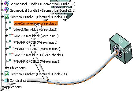
62 Page 62

63 Managing Links from External Data Page 63 This task explains how to link electrical components from the external device list to physical devices. The system has been selected in the previous task. 1. Click the Manage Links button. The device list displays: The components you can link are: equipments connectors pins. You can filter the list: Show all devices: the list displays all the devices referenced in the external data file, even if they are not placed in the geometry. Show only devices present in session: the list displays only the devices placed in the geometry. Show only changed devices: the list displays only the devices which part numbers have been changed in the external data file. 2. Select a component. If the component is not linked to a 3D element, the Link button becomes available.


64 Page Click Link. The 3D Component List opens. 4. Select an equipment which is not linked and click OK. An alternative is to select the component in the specification tree. The equipment is linked, together with the connector that belongs to it. The component list is updated: the equipment, connector and pins are shown as linked in the device list. If all the sub-element part numbers are filled up in the device list with the correct Reference Designator, they are automatically linked. 5. Click Close when you are done.
65 Viewing Related Objects Page 65 This task shows how to use the Related Objects viewer to navigate through the objects connected to the selected object. You can focus on an object and see how it was constructed via its related objects. The related objects command identifies the parent, any children or connected objects and the relationship between objects. It is available when none of the icons of the workbench are activated that is to say when you are in Select command. Accessing related objects can be done in two ways: by clicking the Related Objects icon in the toolbar from the contextual menu, by selecting Related Objects. The different options available are: Reframe on selection: reframes the main 3D window on the Related objects selection. Reframe on selection: the main window selection corresponds to the Related objects selection. The main window display is not reframed. Freeze: freezes the contents of the Related objects window. You can still navigate in the main window: the Related objects view will not be updated. Freeze: the Related objects selection corresponds to the main window selection. View related objects: displays the parent, any children or connected objects. View related objects: only displays the selected objects. Wire: displays the wires contained in the bundle segment, the bundle segments and devices connected to this bundle segment. Wire: hides the wires contained in the bundle segment, shows the bundle segments and devices. Harness: displays the relationship to the harness: connectors, equipments, bundle segments, wires. Harness: hides the children bundle segments, only shows the wires. Sub objects: displays the electrical contents. Sub objects: hides the electrical contents. On a complex electrical system, the 3D view allows you to limit display to a specific area thus enlightening the information regarding this area.

66 Page Select an object: a bundle segment for example. 2. Click the Related Objects button. The Related Objects dialog box appears. The geometry area and the specification tree are reframed on the object selected. 3. Select an object in this window. The dialog box focuses on the object selected: Bundle Segment1.1 (center of the window) and shows the parent and the connected objects: on the left is the parent object (Assembly meaning). It represents the container object. on the right are the children objects (Assembly meaning), connected to the Bundle Segment1.1. They represent the contents. 4. Click the 3D tab to display the geometry.

67 Page Close the dialog box to exit the Related Objects viewer.

68 Defining the Harness Flattening Parameters Page 68 This task explains how to define the flattening parameters. This should be done before using any other function of the Harness Flattening toolbar. Open a new product document using the File -> New... command. Choose the Product type. 1. Click the Harness Flattening Parameters button. The Harness Flattening Parameters dialog box opens on the General tab: This tab lets you define: Name In the specification tree, this icon Flattening Parameters is the default value. is displayed with the name chosen in this field. Minimum angle between two branches
69 Page 69 During the flattening process, this minimum angle is applied every time an angle between two branches is null in the 3D design. That way, bundle segments are never superposed upon one another and can easily be made out. The default value is 5deg. Keep existing tangent between bundle segment and connector during the flattening step This option gives a better flattening shape for flattening. By default this option is not checked. Extract only the supports inside the geometrical bundle The supports which do not belong to the geometrical bundle will not appear in the extracted document. This option allows you to manage two types of support: The supports which must be assembled with the harness during the manufacturing step. This type of support is created inside the geometrical bundle. The supports which are linked to the structure. These supports are added to the harness during the installation step. This type of supports is created outside the geometrical bundle. By default this option is not checked. 2. Select the Drawing tab.

70 Page 70 This tab lets you define: the type of representation for bundle segments: with Double line It is the default value. or Single line. the graphic representation you want to use when replacing devices or supports: keep the 3D projection. It is the default value. or use a 2D detail previously stored in a catalog. In this case, the catalog name and path must be defined in the dedicated option. 3. Select your options and click OK to validate. The parameters you have entered will be automatically applied to the other functions available in this workbench. You will be able to modify them at any time during your session by double-clicking the Flattening Parameters icon in the specification tree.
71 Extracting 3D Data Page 71 This task explains how to extract the geometrical and electrical bundles, with all the devices that are associated to them, in order to duplicate the information they contained in the new document. The 3D document containing a geometrical bundle and an electrical bundle is open as well as the new product document. Make sure the source document has not been modified, otherwise you will be prompted to save it before extracting the data. In the new product document: 1. Click the Extract button. You are prompted to select an electrical or a geometrical bundle. It enables you to extract the information contained in the geometrical or the electrical bundles from your first document. When duplicating an electrical bundle, all the links with the geometrical bundles associated to it are maintained. 2. Select the geometrical bundle you want to extract from the source document, whether in the geometry or in the specification tree.
72 Page 72 When the extraction is performed the source document automatically closes. 3. Save your data.
73 Flattening the Harness Page 73 This task explains how to flatten out bundle segments. The document contains the data extracted in the previous task. You can now flatten the whole geometrical/electrical bundle. To do so: 1. Click the Flatten button. 2. Select the geometrical bundle, in the specification tree or in the geometry. 3. Click OK to validate. The result looks like this:
74 Rotating Bundle Segments Page 74 This task shows you how to rotate a bundle segment. Two types of rotation can be considered: you can rotate a bundle segment around a bundle segment extremity, whatever the direction. bend a bundle segment whatever the selected plane.
75 Rotating Bundle Segments whatever the Selected Plan Page 75 This task shows you how to rotate a bundle segment around a bundle segment extremity whatever the direction. The document contains the flattened harness obtained in the previous task. 1. Click the Rotate button. You are prompted to select a bundle segment extremity in the geometry. It is impossible to select the bundle segment in the specification tree, since the exact position of the selected point has to be known. 2. Select an extremity. A green arrow and a dialog box appear at the same time. a. A green arrow indicating the bundle direction appears on the geometry. The user can modify the angle by selecting the green arrow directly. b. The Define Direction dialog box pops up.

76 Page 76 The default plane is the one you have defined in the Harness Flattening Parameters dialog box at the beginning of your session. 3. Whether you indicate the bundle main direction or you specify its angle and direction values one at a time. a. Enter the main direction. In this example, you can select a geometrical line or a pad edge as the main direction. b. Enter an angle value. As you are changing the angle value, the green arrow is moving to show you the direction the bundle segment is about to take. c. Select two directions to retrieve the angle value. As above, you can select a geometrical line or a pad edge. Once the two directions have been defined, the angle between them is automatically calculated. Note that you can modify the direction of the bundle directly on the geometry by clicking the arc of circle around the selected point. 4. Click Apply.
77 The entered values are applied but the dialog box remains open and you can still modify the inputs. 5. Click OK to validate. The result looks like this. Page 77
78 Bending Bundle Segments Page 78 This task shows you how to rotate a bundle segment around a bundle segment extremity whatever the direction. The document contains the flattened harness obtained in the previous task. 1. Click the Rotate button. 2. Select an intermediate point on a bundle segment. The bundle segment must be selected in the geometry and not in the specification tree, since the exact position of the selected point has to be known. a. The Define Direction dialog box pops up. b. A green arrow indicating the bundle direction appears in the geometry. You can also click the green arrow and circle arc to change the direction the bundle segment is about to take.
79 Page As in the previous task, either you select the main direction, or you indicate the angle or you specify two directions and the angle will be automatically calculated. 4. Click OK to validate. 5. The result looks like this.

80 Scaling Bundle Segments Page 80 This task shows you how to enter a bundle segment fake length. Working with fake lengths enables you to fit the whole harness in the board. The document contains the flattened harness obtained in the previous task. 1. Click the Scale button. You are prompted to select a bundle segment in the geometry. The Scale dialog box pops up. The bundle segment true length is indicated. 2. Enter the fake length you want. 3. Click OK to validate. The support relative positions are maintained when working with fake lengths. If you want to work with true lengths again, press the Restore true length button.
81 Synchronizing the Environment Page 81 This task shows you how to synchronize automatically your 3D flattened geometry at any time during your session. You can add the missing components or remove the additional components, and also synchronize the bundle segment structure. Make sure you have set up the option for the synchronization report repository. The document containing the flattened harness is open from the previous task. Open the initial document as well. 1. In the initial document, select a bundle segment and modify its length, diameter, bend radius, instance name or color. 2. Save your document. 3. Switch back to the flattened harness. 4. Click the Synchronize button. If there is no selection in the specification tree, the first electrical bundle modified will be synchronized. But, if there is more than one electrical bundle, you must select one otherwise a warning will be displayed. If there is no electrical bundle, all the geometrical bundles will be selected and updated. You can do a multi-selection (devices, supports, etc. at the same time). The Synchronize dialog box pops up: During the synchronization step, only the selected options will be performed. This will optimize the synchronization length. The html report will be generated accordingly and will show only the selected options.

82 Page 82 This dialog box lets you define what you want to synchronize: Components Components allows you to choose which components you want to update: Devices Bundle segments Supports Wires. You can select at the same time as many components as needed. Actions
83 Page 83 Actions allows you to customize the actions during the synchronization step: Remove the components deleted in 3D Add the components added in 3D Replace the reference of components changed in 3D (it can only be used with the Supports or Devices options activated.) Synchronize the bundle segment structure (it can only be used with the Bundle Segments option activated.) It allows to: add or remove intermediate bundle segments replace one or more bundle segments with one or more different bundle segments. Synchronize the attributes. For the synchronization of the position of supports, you must select Bundle Segments instead of Supports. You can select as many actions as needed. Options Options: Simulation (generates a report without applying changes to the flattened document.) Html report (generates the report in the Tools -> Options predefined folder.) Automatic flattening on the added components Reset the synchronization attributes. (all components will be set to the False value again, so only the newly changed components will be set to True. You can use Edit/Search to retrieve quickly all components.) 5. Click OK to validate.

84 Page 84 A status bar appears showing the synchronization progress: Here are the different steps that can be seen through the synchronization process according to the options previously selected: Analyze step is processing Replaced components synchronization is processing Removed components synchronization is processing Bundle segment structure synchronization is processing Added components synchronization is processing Attributes synchronization is processing Generating Html report An HTML file is generated in the synchronization report repository if Html report is checked. For more information about the html report, see Generating the HTML Report during the Synchronization. The extracted document is updated if Simulation is not checked: The attributes that have been modified will show the Synchronize property set to True. Once the attributes have been reset, the Synchronize property will turn back to False.

85 Page 85 Thus you can visualize what electrical attributes have been modified in the initial model.
86 Generating the HTML Report during the Synchronization Page 86 This file explains the contents of the Html Report created during the synchronization. The HTML report is composed of accurate fields, which describe the changes that occurred during the synchronization. Only the tables which have modified components are shown, except for the Synchronization Parameters table, which is always present. They rely on the fields that can be found in the Synchronize dialog box. Synchronization Parameters: Option: Simulation Automatic flattening on added components Reset the synchronization attributes. Action: Remove the components Add the components Replace the reference of components Synchronize the bundle segment structure Synchronize the attributes. Components: Bundle segments Devices Supports Wires. List of Removed Components: Bundle Name Bundle Segments Devices Supports Wires. List of Added Components: Bundle Name
87 Bundle Segments Devices Supports Wires. Page 87 List of Replaced Components: Bundle Name Devices Supports. List of Bundle Segment Structure Modifications: Bundle Name Modification Number Before After. List of Bundle Segment Attribute Modifications: Bundle Name Name Reference Designator Length Diameter Bend Radius Separation Code Color. List of Device Attribute Modifications: Bundle Name Instance Name Reference Designator Sub Type Part Number. List of Support Attribute Modifications: Bundle Name Instance Name Part Number Support Position. List of Wire Attribute Modifications: Bundle Name Instance Name Reference Designator
88 Sub Type Diameter Linear Mass Bend Radius Separation Code Color Modified Route. Page 88 List of Elements Showing an Error: Bundle Name Instance Name Error Message. In the Synchronization Parameters table, the options that have been selected in the Synchronize dialog box are set to YES, the others are set to NO: Synchronization Parameters Options Actions Components Simulation NO Remove components YES Bundle segments YES Automatic flattening on added components Reset the synchronization attributes YES Add components YES Devices YES NO Replace component reference YES Supports NO Synchronize bundle segment structure NO Wires NO Synchronize attributes YES In all the fields of the attribute and structure modification list, two lines appear: The first line indicates the status of the component before synchronization. The second line indicates the parameters that have been changed with the synchronization. List of Wire Attribute Modifications Bundle Name Instance Name Reference Designator Sub Type Diameter Linear Mass Bend Radius Separation Code Color Modified Route
89 Page 89 Electrical Bundle2.1 Wireplus1 Wire-plus1 2mm 0kg_m 20mm Attribute unset yellow 5mm NO The added, replaced, removed component fields have one line per element indicating the modifications. List of Added Components Bundle Name Bundle Segments Devices Supports Diameter Wires Wire-minus1 Electrical Bundle2.1 Wire-minus2 Wire-minus3 Find hereafter the list of the errors that can occur during the synchronization and that will be reported in the Html file: "The 3D harness flattening and 3D harness design link is broken" "Error during the Analyze" "Error during the Remove Component Synchronization" "Error during the Bundle Segment Structure Synchronization" "Error during the Add Component Synchronization" "Error during the Attribute Access" "Error during the Replace Component Synchronization" "Error during the Bundle Segment Attribute Synchronization - Different Bundle Segment Structure" "Error during Attribute Synchronization - Internal link failed to 3D harness flattening from 3D harness design" "Error during the Bundle Segment Attribute Synchronization - Different Number of Supports" "Error during the Bundle Segment Attribute Synchronization - Different Supports Configuration" "Error during the Add Component - The original component document is not saved" "Error during Wire Route Synchronization" "Error during the Device Move" "Error during Bundle Segment Move" List of Elements Showing an Error Bundle Name Instance Name Error Message
90 Page 90 Geometrical Bundle2.1 Connector_F.1 Connector_F.2 Error during Add Component Synchronization Error during Add Component Synchronization Note: The Html report is generated with a default Cascading Style Sheet document (.css) that can be personalized.
91 Using the Drawing Capabilities Page 91 You can use these functionalities only if a Drafting license is available. These functionalities allow you to take advantage of the Interactive Drafting capabilities: You can easily create a drawing of the flattened harness. You can use the various drawing representation options. The Wire Annotation command in the Interactive Drafting workbench allows you to create a wire annotation on bundle segments and connectors. You can now gain in efficiency by creating dimensions for technological features such as electrical harness. For a drawing created with a flattened document, you can have dimensions only on bundle segments. The Interactive Drafting workbench lets you define and store text templates into catalogs to be used when creating texts associated to technological objects: Create Text Templates. Store Text Templates into a Catalog. Annotate Drawings using Text Templates.
92 Customizing a Drawing View Page 92 This task shows you how to generate a drawing view, using various representation options. The document contains the harness obtained in Flattening the Harness. Make sure the Drafting -> View options are set as follows: Open the Tools -> Options... menu, then Mechanical Design: In the Geometry generation / Dress-up frame, check the following options: Project 3D wireframe Project 3D points For more information, refer to the View tab documentation. 1. Open the Tools -> Options... menu, then in the Equipment & Systems category, choose the Electrical 3D Design item to define a graphic replacement catalog. To do so: click the Add button browse to the catalog. click OK to validate. A mapping will be done between the connector external reference (or the part number if the external reference is not valuated) and the name of the 2D detail. If an equivalence is found, the corresponding 2D detail will replace the connector in the drawing. If not, the 3D projection will be displayed. 2. In the Drawing tab, select: the double line for bundle segment representation the 2D detail option for device graphical representation

93 Page Click OK to validate. 4. Perform the mapping: a. Right-click a connector to display the properties, b. Click the More... button to display the Electrical tab. c. Enter a value in the External Reference field. d. Click OK to validate. Once this is done, you will generate the drawing. 5. Open a new drawing document.
94 Page Click the Front View button and select a face of the connector as Plane. The drawing document updates according to this choice: The connectors have been replaced with the chosen 2D detail and bundle segments are displayed with a double line. Note that the External Reference attribute does not exist for the support and you need to create it. To do so: Right-click the support to display the Properties. At the bottom of the Product tab, click the Define other properties... button. The dialog box displays:


95 Page 95 Select String in the combo and click the New Parameter of type button. Edit the name: External Reference This property is added to the support. You can now enter a value to map a catalog 2D detail.

96 Generating a Drawing Page 96 You can perform this scenario only if a Drafting license is available. This task explains how to generate a drawing from the flattened harness. The document contains the flattened harness obtained in the previous task. 1. Open a new product document using the File -> New... command. Choose the Drawing type and click OK to validate the default New Drawing parameters. CATIA switches to the Drafting workbench. 2. Click the Front View button. You are prompted to select a reference plane on the 3D geometry. 3. Click a plane in the flattened harness document: for example the face of a connector. The drawing document updates according to this choice:
97 Creating Wire Annotations Page 97 A dedicated command is available in the drafting workbench to create a wire annotation on bundle segments and connectors. The wire attributes in the annotation can be customized. The document contains the flattened harness obtained in the previous task. 1. Generate a drawing like it is explained in Generating a Drawing. 2. In the Drafting workbench, click the Wire Annotation button. Two dialog boxes open:

98 Page 98 The Tools Palette, which allows you to show or hide the wire annotation dialog box: When it looks like this, the Wire Attributes dialog box is visible. When it looks like that, the Wire Attributes dialog box is not visible: Click the Tools Palette to make it visible. The Wire Attributes dialog box, which allows you to select the attributes you want to see as annotations: To add an attribute from Available to Favorites, select the attribute of interest then click the right arrow. To remove an attribute from Favorites, select it in the list then click the left arrow. By default, the last Favorites used are available when the dialog box is re-opened. If you want to save different favorite lists: select the attributes needed, enter a name in the input field then validate. You can then display your favorite list in the combo box. 3. Choose Reference designator, Diameter, Length and Bend Radius for example. 4. Then, select a bundle segment or a connector in the geometry. A table is created, showing all the attributes that you have selected in Favorites:
99 Page 99 If you want to add another wire annotation, you have to click again the Wire Annotation button before selecting a bundle segment or a connector. There is an automatic update of the modifications except if you remove or add some components. If you want to customize the graphical representation of the table, right-click to display the contextual menu then select Properties.
100 Creating Intra-Technological Feature Dimensions Page 100 This task will show you how to create dimensions for technological features such as electrical harness. You need an Electrical Harness Assembly license for the purpose of this scenario as we will be dimensioning Electrical Harness Assembly features. Intra-technological feature dimensioning is also available for other applications such as Structure Functional Design or Ship Structure Detail Design. For more information on the availability of technological feature dimensioning for a given workbench, refer to the related documentation. Refer to Before you Begin for general information about technological feature dimensions. Open the ElectricalAssembly.CATProduct document and make sure it is loaded in the Electrical Harness Assembly workbench (if necessary, select Start -> Equipment & Systems -> Electrical Harness Assembly to launch the workbench). Open the ElectricalAssembly.CATDrawing document. 1. Click the Multiple Intra Technological Feature Dimensions icon from the Dimensioning toolbar, Technological Feature Dimensions sub-toolbar. You can also click the Technological Feature Dimensions icon Multiple Intra Technological Feature Dimensions icon and then select the from the Tools Palette. 2. Select the feature that you want to dimension. Note that the name of a feature is displayed as a help as you move the cursor over it.
101 Page 101 The dimension is created as specified by the feature. In this specific example, the bundle segment specifies that the dimension should provide its overall length. The dimension creation command remains active.
102 Page Repeat step 2 for each additional feature that you want to dimension. 4. End the dimension creation by clicking anywhere in the drawing (but not on a technological feature) or by lining-up the dimension. The intra-feature dimensions are created as specified by the feature. You can now handle the dimension(s) just like any other dimension.

103 Creating Text Templates Page 103 This task will show you how to create text templates. Before you begin, you need to make sure that the package corresponding to the type of object for which you want to create a template is correctly loaded. For the purpose of this scenario, you will load the Product package. Go to Tools -> Options -> General -> Parameters and Measure and click on the Language tab. Check Load extended language libraries and uncheck All packages. From the Available Packages list, select ProductPackage and click on the right arrow to add it to the Packages to load list. Click OK, and then exit and re-start the software. Create a new drawing. 1. Click the Text icon from the Annotations toolbar. 2. Click anywhere in the drawing. A green frame appears, as well as the Text Editor dialog box. 3. In the Text Editor dialog box, type Part number:. 4. Without closing the Text Editor dialog box, right-click the frame and select Insert link template from the contextual menu which is displayed. 5. In the Insert Link Template dialog box which is displayed, select the ProductPackage dictionary, the Product type and the PartNumber attribute, and click Insert.
, click Insert and then Close. 8. Click OK in the Text Editor dialog box.")
104 Page Back in the Text Editor dialog box, press the Enter key and type Revision:. 7. Back in the Insert Link Template dialog box, select the Revision attribute (leave the other fields as is), click Insert and then Close. 8. Click OK in the Text Editor dialog box. The text template is now created. 9. Make sure the text template is selected and click the Frame icon in the Text Properties toolbar. 10. From the Frames sub-menu, choose the Scored Rectangle frame. 11. Right-click the text template, and select Add Leader from the contextual menu. 12. Click in the drawing to end the leader creation. The text template is now set.
105 Page Right-click the text template, and select Properties from the contextual menu. 14. Click the Feature Properties tab in the Properties dialog box which is displayed. 15. In the Feature Name field, type Part number & Revision and click OK. You will use this feature name to identify this text template in the future. 16. Create another text by repeating steps 1 to 3, this time typing Part name: in the Text Editor dialog box. 17. Repeat steps 4 and 5, this time selecting the Name attribute in the Insert Link Template dialog box. 18. Click Close in the Insert Link Template dialog box and then OK in the Text Editor dialog box. The text template is now created. 19. Make sure the text template is selected and in the Graphic Properties toolbar, choose green from the Color list. The text template is now set. 20. Repeat steps 13 to 15, this time typing Part name in the Feature Name field. You will use this feature name to identify this text template in the future. 21. Select File -> Save As and save the drawing as a.catdrawing document. Now that your text templates are defined, you need to store them in a catalog.
106 Storing Text Templates in a Catalog Page 106 This task will show you how to store text templates in a catalog. For more information on catalogs, refer to the Using Catalogs chapter in the Infrastructure User's Guide. Open the TextTemplates.CATDrawing document. 1. Select File -> New. 2. In the New dialog box, select CatalogDocument from the list of types and click OK. The Catalog Editor workbench is launched and a new catalog is created. 3. In the left-hand pane, double-click Chapter.1 to activate it. 4. Select Insert -> Add Family... The Component Family Definition dialog box is displayed. 5. Type Text templates in the Name field. 6. Make sure Standard is selected in the Type field, and click OK. The family is created. 7. For more convenience, select Window -> Tile Horizontally to display your Catalog Editor and Drafting windows at once. 8. In the Drafting window, select one of the text templates, e.g. Part number & Revision. 9. In the left-hand pane of the Catalog Editor window, double-click Text templates to activate it. 10. Select Insert -> Add Component... The Description Definition dialog box is displayed. 11. On the Reference tab, click the Select external feature button. The dialog box is updated with information about the selected text template, i.e. Part number & Revision.


107 Page Click OK. The selected text template is listed on the Reference tab, in the right-hand pane of the Catalog Editor window. 13. Go back to the Drafting window and select the other text templates, e.g. Part name. 14. Return to the Catalog Editor window and repeat steps 10 and 11. The dialog box is now updated with information about the Part name text template. 15. Click OK. Both selected text templates are now listed on the Reference tab, in the right-hand pane of the Catalog Editor window.
108 Page Select File -> Save As and save the catalog as a.catalog document.
109 Annotating Drawings Using Text Templates Page 109 This task will show you how to annotate drawings using text templates stored in a catalog. Before you begin, you need to make sure that the package corresponding to the type of object for which you want to create a template is correctly loaded. For the purpose of this scenario, you will load the Product package. Go to Tools -> Options -> General -> Parameters and Measure and click on the Language tab. Check Load extended language libraries and uncheck All packages. From the Available Packages list, select ProductPackage and click on the right arrow to add it to the Packages to load list. Click OK, and then exit and re-start the software. Open the GEAR-REDUCER.CATDrawing document. 1. Click the Text Template Placement icon from the Annotations toolbar. 2. In the Place Text Template dialog box, browse to select the TextTemplates.catalog document. This document is located in your documentation installation folder (by default, this folder is C:\Program Files\Dassault Systemes\XXXdoc\online\), in cfysa_c2\samples\drafting. Leave the Place Text Template dialog box open to perform the next steps. 3. On any view, select the part that you want to annotate, making sure that you click where you want the anchor point of the annotation to be located. Note that the name of a part is displayed as a help as you fly the cursor over it.
110 Page 110 The Place Text Template dialog box now lists all the templates available in the selected catalog and which can be applied to the selected object.
111 Page In the Place Text Template dialog box, select the text template that you want to apply, Part number & Revision for example. The annotation is created at the point you clicked when selecting the part to annotate, and contains information retrieved from the 3D part. Note that this annotation is associative to the 3D part. 5. If you want, select the other text template (Part name). Note that this annotation will also be created at the point you clicked, so it will overlap the first annotation. For better results, you will have to move it afterwards. 6. Repeat steps 3 to 5 for other parts that you want to annotate. Note that the last template you selected in the Place Text Template dialog box remains active when annotating other parts. You can de-activate it by clicking the Clear selection button. 7. When you're done, click Close to close the Place Text Template dialog box. You can also multi-select the parts that you want to annotate (using the Ctrl key) prior to clicking the Text Template Placement icon.
112 Defining the Report Format Page 112 This task shows you how to define the report format. You use this function, together with the function described in Generating a Report, to get the values of properties of objects in a document. Examples from the Piping Design workbench are used here. Substitute the appropriate resource or directory when working in another workbench. Before you generate a report you need to define its format. This means deciding which properties you are interested in. This report format is kept in a file which you can use to generate reports from other documents. To use this function you must first set up an option: a. Click Tools -> Options -> General -> Parameters and Measure b. Select the Language tab. c. Under Language check Load extended language libraries. d. Click OK to validate. 1. Click Tools -> Report -> Define. The Report Definition dialog box displays.

113 Page Enter a Report Name and select a directory location. 3. Enter a Report Title - you can select anything but you must enter a title. 4. Check the Show Inherited Attributes box if you want to. 5. Click the down arrow and select the Dictionary related to your program. 6. Select the Type of object. The list of attributes you see in Step 7 depends on the type you select here. However, when you
114 Page 114 generate a report you will get values for all objects in the document that have the attributes in your report format. If you want to limit the objects for which you get a report you must create a query (Step 9). 7. Select an attribute in the Attribute field and click the Add button. The attribute is added in the window. Add as many attributes as you want to. 8. You can further refine your report by using the Edit -> Search function to define a query. This allows you to generate a report on a narrower selection of check valve, say, of a certain size, instead of all check valves in your document. The queries you create are available for selection when you click the arrow in the Query Name field above. Detailed instructions on using the Search function can be found in the Infrastructure User's Guide under Basic Tasks - Selecting Objects. Briefly: a. Click Edit -> Search to bring up the Search dialog box. b. Select the Advanced tab, then select a workbench, type of object and attribute you are interested in. c. Clicking the Add to Favorites button brings up the Create a Favorite Query dialog box, where you can name the query and save it.

115 Generating a Report Page 115 This task explains how to generate a report listing values of selected properties. Before you do this you need to define the report format. Examples from the Piping Design workbench are used here. Substitute the appropriate resource or directory when working in another workbench. 1. Click Tools -> Report -> Generate. The Generate Report dialog box displays. 2. Click the Open button and select the format you want to use for your report, in this case NewReport. 3. If you had defined a query in your report format then check Objects From Predefined Query. 4. If you select one or more objects in the document then check Currently Selected Objects. 5. Check All Objects in Document if you want a report on all objects in your document. 6. Click OK and select a format, such as HTML, when you are prompted. The report is generated. It shows values for all properties defined in your report format for all objects in the document that have them. Where an object does not have a property the report displays asterisks.

116 Page Click Insert in Document if you want to display these values in your document. To generate the report from a schematic and insert it in a schematic, click the Insert in Document button and click anywhere in your drawing. To generate the report from a 3-D document and insert it in a schematic, click the Insert in Document button and select the sheet or view in the specifications tree. Do not select a point in the sheet. The data will be placed at the origin of the sheet or view, and can be moved to another location. 8. Click Save As to save the report. Specify a file name and location.

117 Workbench Description Page 117 Electrical 3D Design and Documentation application windows look like this: Electrical 3D Design & Documentation - Assembly Electrical 3D Design & Documentation - Part
118 Page 118 Assembly Toolbars Part Toolbars
119 Assembly Toolbars Page 119 This section describes the various icons available in the Electrical 3D Design Assembly workbench. The toolbars are located on the right in the default set-up except for the Catalog Browser, which is located in the horizontal bottom toolbar. Electrical Device Definition Harness Definition External Electrical System Harness Flattening Catalog
120 Page 120 Related Objects See Viewing Related Objects See Defining an Equipment See Defining a Connector See Defining a Cavity See Defining a Termination See Defining a Bundle Connection Point See Defining a Connector Connection Point See Defining a Cavity Connection Point See Connecting Devices See Disconnecting Devices See Creating a Geometrical Bundle See Defining Bundle Segments See Creating an Electrical Bundle See Selecting External Systems See Managing Links See Routing Wires from External Data See Defining the Harness Flattening Parameters See Extracting Data
121 Page 121 See Flattening the Harness See Rotating Bundle Segments See Scaling Bundle Segments See Synchronizing the Environment See Using a Catalog, Using Catalogs See Using Smart Placement from Catalog
122 Part Toolbars Page 122 This section describes the various icons available in the Electrical Library workbenches. The toolbars are located on the right in the default set-up except for the Catalog Browser, the Measure and the Update icons which are located in the horizontal bottom toolbar. Electrical Device Definition Bundle Segment Definition Catalog See Defining an Equipment See Defining a Connector See Defining a Cavity See Defining a Termination See Defining a Bundle Connection Point See Defining a Connector Connection Point See Defining a Cavity Connection Point
123 Page 123 See Creating a Support See Defining Bundle Segments See Using Catalogs
124 Page 124 Customizing Electrical 3D Design & Documentation Before you start your first working session, you can customize the way you work to suit your habits. This type of customization is stored in permanent setting files: these settings will not be lost if you end your session. 1. Select the Tools -> Options command. The Options dialog box displays. 2. Choose the Equipment & Systems category in the left-hand box. 3. Click the Electrical 3D Design workbench. The options for 3D Design settings appear, organized in tab pages. 4. Select the tab corresponding to the parameters to be customized. Parameters in this tab... General Harness Flattening Harness Management Wire Routing Electrical Process Interfacing Allow you to customize... the automatic compass the synchronization report repository the bundle segment creation options the options to optimize the routing the external data file repository 5. A tab located in the Infrastructure category, in the Part Infrastructure workbench, also interfere with Electrical 3D Design: General 6. Another tab located in the Mechanical Design category, in the Drafting workbench, also interfere with Electrical 3D Design: View 7. Change theses options according to your needs. 8. Click OK when done.
125 General Page 125 This page deals with the options concerning: the automatic compass Click here to see the parent page. Automatic Compass Snap to placed element if this option is checked, you take advantage of the compass: when you place an element, the compass snaps to this element allowing you to modify the orientation and location. By default this option is checked.
126 Harness Flattening Page 126 This page deals with the options concerning: the synchronization report repository the graphic replacement catalog Click here to display the parent page. Synchronization Report Repository Path Indicate the folder path where you want to save the synchronization report html files. By default, this field contains:...\dassaultsystemes\cattemp. Graphic Replacement Catalog Catalog path and Catalog name Indicate the catalog path and name where the drawing 2D details are stored. By default, this field is empty.
127 Harness Management Page 127 This page deals with the options concerning: the bundle segment creation Click here to see the parent page. Bundle Segment Creation Bundle segment color Use the color chooser to define the bundle segment color at creation.
128 Wire Routing Page 128 This page deals with the options concerning: the separation code file the bundle segment bend radius update Click here to see the parent page. Separation Code File This option is used to define separation code rules to optimize the routing. No rule The separation code is not used. The routing is done according to the shortest route found. It is the default value. File based The separation codes may be File Based. In this case, define the path to access the compatibility table by clicking the Browse button to choose the separation code file. This file is used during the automatic routing. Bundle Segment Bend Radius Update According to the wire bend radius
129 Page 129 Three modes are available: Never: no update of the bundle segment minimum bend radius is performed. Always: the greatest bend radius of the wires routed in the bundle segment determines the segment bend radius to be applied. Conditional: the wire bend radius is taken into account for update when it is greater than the bundle segment bend radius. The default mode is Always.
130 Electrical Process Interfacing Page 130 This page deals with the options concerning: the electrical ixf repository path Click here to see the parent page. Electrical ixf Data Repository System repository You are required to identify the path of the folder in which the XML files available are stored. Use to locate the ixf systems repository. By default the field is empty.

131 Part Infrastructure for Electrical 3D Design Page 131 This page deals with the options concerning: the external references: keep link with selected object Click here to display the parent page. Part Infrastructure General option Click here to know more about the Part Infrastructure General options. Keep link with selected object You need to check this option to take advantage of the associativity between the construction points or part body and the bundle segment. By default, this option is unchecked.
Electrical Harness Flattening
 Electrical Harness Flattening Overview Conventions What's New? Getting Started Accessing the Electrical Harness Flattening Workbench Defining the Harness Flattening Parameters Extracting Data Flattening
Electrical Harness Installation
 Electrical Harness Installation Page 1 Overview Conventions What's New? Getting Started Entering the Workbench Setting Up the Options Creating a Bundle Segment Document Creating Construction Points Defining
Electrical Library Version 5 Release 13. Electrical Library
 Electrical Library Page 1 Overview Conventions What's New? Getting Started Entering the Electrical Part Design Workbench Defining a Single Insert Connector Defining a Cavity Connection Point Entering Electrical
Electrical Wire Routing
 Electrical Wire Routing Page 1 Overview Conventions What's New? Getting Started Accessing the Workbench Creating the Bundle Selecting Systems with External Data Routing Wires from External Data User Tasks
Equipment Support Structures
 Equipment Support Structures Overview Conventions What's New? Getting Started Setting Up Your Session Creating a Simple Structural Frame Creating Non-uniform Columns Creating Plates with Openings Bracing
Fastening Review Overview Basic Tasks DMU Fastening Review Interoperability Workbench Description Customizing Index
 Fastening Review Overview Conventions Basic Tasks Displaying Joined Parts in a Balloon Running the Fastening Rules Analysis Reporting Creating Structural Reports Creating Flat Reports DMU Fastening Review
Tolerance Analysis of Deformable Assembly
 Tolerance Analysis of Deformable Assembly Overview Conventions What's New? Getting Started Entering the Workbench Creating a New Analysis Importing the Assembly Definition Computing a Tolerance Analysis
DMU Engineering Analysis Review
 Page 1 DMU Engineering Analysis Review Preface Using This Guide Where to Find More Information Conventions What's New? Getting Started Inserting a CATAnalysis Document Using DMU Space Analysis From CATAnalysis
DMU Space Engineering Assistant User Guide
 DMU Space Engineering Assistant User Guide Overview Conventions What's New? Getting Started User Tasks Setting Up Your Session Running an Interference Analysis Workbench Description DMU Space Engineering
DMU Space Engineering Assistant User Guide
 Page 1 DMU Space Engineering Assistant User Guide Overview Conventions What's New? Getting Started User Tasks Setting Up Your Session Running a Interference Workbench Description DMU Space Engineering
Equipment Support Structures
 Page 1 Equipment Support Structures Preface Using This Guide Where to Find More Information Conventions What's New? Getting Started Setting Up Your Session Creating a Simple Structural Frame Creating Non-uniform
Product Structure Version 5 Release 13. Product Structure
 Product Structure Page 1 Site Map Preface Conventions What's New? Basic Tasks Entering the Product Structure Workbench Opening a CATProduct with a Progress Bar Selecting Products only Selecting Modes Inserting
DMU Engineering Analysis Review
 DMU Engineering Analysis Review Overview Conventions What's New? Getting Started Entering DMU Engineering Analysis Review Workbench Generating an Image Visualizing Extrema Generating a Basic Analysis Report
Circuit Board Design Version 5 Release 13. Circuit Board Design
 Circuit Board Design Page 1 Overview Conventions What's New? Getting Started Accessing the Circuit Board Workbench Creating a Board Pocket and Holes Constraint Area Exporting Data Importing Data User Tasks
NC Manufacturing Verification
 NC Manufacturing Verification Overview Conventions What's New? User Tasks Accessing NC Manufacturing Verification Comparing the Machined Stock Part and the Design Part Pick Point Analysis in Video Mode
Electrical System Functional Definition
 Electrical System Functional Definition Overview Conventions What's New? Getting Started Creating a New System Creating Equipment Creating Connectors Creating a Signal Connecting Saving Your System User
Advanced Meshing Tools
 Page 1 Advanced Meshing Tools Preface Using This Guide More Information Conventions What's New? Getting Started Entering the Advanced Meshing Tools Workbench Defining the Surface Mesh Parameters Setting
Knowledge Expert Overview What's New? Getting Started Basic Tasks Advanced Tasks Reference
 Knowledge Expert Overview Conventions What's New? Getting Started Creating an Expert Check Creating an Expert Rule Basic Tasks About RuleBases Storing a Rule Base in a Catalog Using a Rule Base Stored
NC Manufacturing Verification
 NC Manufacturing Verification Page 1 Preface Using This Guide Where to Find More Information Conventions What's New? User Tasks Accessing NC Manufacturing Verification Comparing the Machined Stock Part
Piping Design. Site Map Preface Getting Started Basic Tasks Advanced Tasks Customizing Workbench Description Index
 Piping Design Site Map Preface Getting Started Basic Tasks Advanced Tasks Customizing Workbench Description Index Dassault Systèmes 1994-2001. All rights reserved. Site Map Piping Design member member
Mechanical Design V5R19 Update
 CATIA V5 Training Foils Mechanical Design V5R19 Update Version 5 Release 19 August 2008 EDU_CAT_EN_MD2_UF_V5R19 1 About this course Objectives of the course Upon completion of this course you will be able
Electrical System Functional Definition
 Electrical System Functional Definition Preface What's New? Getting Started Basic Tasks Advanced Tasks Workbench Description Customizing Glossary Index Dassault Systèmes 1994-2000. All rights reserved.
DMU Space Analysis Version 5 Release 13. DMU Space Analysis
 Page 1 DMU Space Analysis Preface Using This Guide More Information Conventions What's New? Getting Started Setting Up Your Session Measuring Minimum Distances Sectioning Detecting Clashes Measuring Between
Structure Preliminary Layout
 Structure Preliminary Layout Overview Conventions What's New? Getting Started Setting Up Your Session Defining the Hull Form Setting Up Your Grid Creating Molded Forms Creating a Compartment Creating Boundaries
Aerospace Sheetmetal Design
 Aerospace Sheetmetal Design Page 1 Overview Conventions What's New? Getting Started Entering the Aerospace SheetMetal Design Workbench Defining the Aerospace SheetMetal Parameters Creating a Web from a
Systems Space Reservation
 Systems Space Reservation Preface Using This Guide What's New? Getting Started Enter the Workbench Create an Equipment Reservation Set Correct Working Units and Grid Changing the Current Axis Saving Documents
Prismatic Machining Overview What's New Getting Started User Tasks
 Prismatic Machining Overview Conventions What's New Getting Started Enter the Workbench Create a Pocketing Operation Replay the Toolpath Create a Profile Contouring Operation Create a Drilling Operation
FreeStyle Shaper Optimizer & Profiler
 FreeStyle Shaper Optimizer & Profiler Page 1 Preface Using This Guide More Information What's New? Getting Started Starting the FreeStyle Workbench Creating a First Surface Editing the Surface Creating
DMU Fitting Simulator
 Page 1 DMU Fitting Simulator Preface Using This Guide More Information Conventions What's New? Getting Started Using Tracks Starting a Session Recording a Track Using Automatic Path Finder Using the Smooth
DMU Optimizer Overview What's New? Getting Started User Tasks
 DMU Optimizer Overview Conventions What's New? Getting Started Starting a Session Generating a Silhouette Generating a Wrapping Generating a Thickness Generating an Offset Generating a Free Space User
Preface. Version 5 Release 5. Mold Tooling Design
 Version 5 Release 5 Mold Tooling Design Preface Getting Started Basic Tasks Advanced Tasks Customization Workbench Description Glossary Index Preface The CATIA Version 5 Mold Tooling Design application
Compartment and Access
 Compartment and Access Page 1 Preface Using This Guide What's New? Getting Started Entering the Workbench Set Correct Working Units and Grid Saving Documents User Tasks Creating/Modifying Wall Systems
FreeStyle Shaper & Optimizer
 FreeStyle Shaper & Optimizer Preface What's New Getting Started Basic Tasks Advanced Tasks Workbench Description Customizing Glossary Index Dassault Systèmes 1994-99. All rights reserved. Preface CATIA
Structure Preliminary Layout
 Page 1 Structure Preliminary Layout Preface Using This Guide Where to Find More Information What's New? Getting Started Setting Up Your Session Defining the Hull Form Setting Up Your Grid Creating Molded
Compartment and Access
 Compartment and Access Preface Using This Guide What's New? Getting Started Entering the Workbench Set Correct Working Units and Grid Saving Documents User Tasks Creating/Modifying Wall Systems Building
Publication Number spse01695
 XpresRoute (tubing) Publication Number spse01695 XpresRoute (tubing) Publication Number spse01695 Proprietary and restricted rights notice This software and related documentation are proprietary to Siemens
Publication Number spse01695
 XpresRoute (tubing) Publication Number spse01695 XpresRoute (tubing) Publication Number spse01695 Proprietary and restricted rights notice This software and related documentation are proprietary to Siemens
Knowledge Advisor Overview What's New? Getting Started User Tasks
 Knowledge Advisor Overview Conventions What's New? Getting Started Using Parameters Using Formulas Using Rules Using Checks User Tasks Working with Parameters Creating a Parameter Introducing Parameters
Electrical Cableway Routing
 Electrical Cableway Routing Preface Using This Guide What's New? Getting Started Entering the Workbench Placing a Hanger Routing a Loft Through Hangers Placing a Conduit on a Run Saving Documents Updating
HVAC Diagrams Preface What's New? Getting Started User Tasks
 HVAC Diagrams Preface Using This Guide What's New? Getting Started Entering the Workbench Setting up Working Units and Grid Placing Components Routing an HVAC Line Placing Components in a Line Repositioning
Piping & Instrumentation Diagrams
 Piping & Instrumentation Diagrams Preface Using This Guide What's New? Getting Started Entering the Workbench Setting up Working Units and Grid Placing Components Routing a Piping Line or I & C Loop Placing
Structure Design Administration
 CATIA V5 Training Exercises Structure Design Administration Version 5 Release 19 January 2009 EDU_CAT_EN_SRA_AX_V5R19 1 Table of Contents Step 1: Creating a New Project 3 Do It Yourself 4 Step 2: Adding
SheetMetal Design Version 5 Release 13. SheetMetal Design
 SheetMetal Design Page 1 Overview Conventions What's New? Getting Started Entering the Workbench Defining the Parameters Creating the First Wall Creating the Side Walls Creating a Cutout Creating Automatic
Piping & Instrumentation Diagrams
 Page 1 Piping & Instrumentation Diagrams Preface Using This Guide What's New? Getting Started Entering the Workbench Setting up Working Units and Grid Placing Components Routing a Piping Line or I & C
3 AXIS STANDARD CAD. BobCAD-CAM Version 28 Training Workbook 3 Axis Standard CAD
 3 AXIS STANDARD CAD This tutorial explains how to create the CAD model for the Mill 3 Axis Standard demonstration file. The design process includes using the Shape Library and other wireframe functions
CATIA Electrical Space Reservation TABLE OF CONTENTS
 TABLE OF CONTENTS Introduction...1 Manual Format...2 Electrical Reservations...3 Equipment Reservations...5 Pathway Reservations...31 Advanced Reservations...49 Reservation Analysis...67 Clash...69 Sectioning...73
Inventor 201. Work Planes, Features & Constraints: Advanced part features and constraints
 Work Planes, Features & Constraints: 1. Select the Work Plane feature tool, move the cursor to the rim of the base so that inside and outside edges are highlighted and click once on the bottom rim of the
Knowledge Expert Version 5 Release 13. Knowledge Expert
 Knowledge Expert Page 1 Preface Using this Guide What's New? Getting Started Basic Tasks About RuleBases Storing a Rule Base in a Catalog Using a Rule Base Stored in a Catalog Importing a Rule Base Activating
Getting Started. The main tasks described in this section are the following:
 Getting Started Getting Started Before getting into the detailed instructions for using Interactive Drafting workbench, the following tutorial aims at giving you a feel of what you can do with the product.
Human Posture Analysis
 Human Posture Analysis Overview Conventions What's New? Getting Started Creating a Manikin User Tasks Using the Posture Editor Selecting or Editing the DOF (Degree of Freedom) Displaying and Editing Angular
USING THE TRIBALL FOR POSITIONING
 USING THE TRIBALL FOR POSITIONING Although many important positioning tools are available, none are as versatile as the TriBall tool. This TriBall tool offers complete repositioning of many items: Shapes
Introduction to SolidWorks Basics Materials Tech. Wood
 Introduction to SolidWorks Basics Materials Tech. Wood Table of Contents Table of Contents... 1 Book End... 2 Introduction... 2 Learning Intentions... 2 Modelling the Base... 3 Modelling the Front... 10
Lesson 3: Surface Creation
 Lesson 3: Surface Creation In this lesson, you will learn how to create surfaces from wireframes. Lesson Contents: Case Study: Surface Creation Design Intent Stages in the Process Choice of Surface Sweeping
Schematics in ArcMap Tutorial
 Schematics in ArcMap Tutorial Copyright 1995-2010 Esri All rights reserved. Table of Contents Introducing Schematics in ArcMap Tutorial........................ 3 Exercise 1: Getting familiar with Schematics
Proprietary and restricted rights notice
 Proprietary and restricted rights notice This software and related documentation are proprietary to Siemens Product Lifecycle Management Software Inc. 2012 Siemens Product Lifecycle Management Software
Pipe Networks CHAPTER INTRODUCTION OBJECTIVES
 CHAPTER 11 Pipe Networks INTRODUCTION Pipe networks are integral to a site-design solution. The piping system s complexity can vary from simple culverts to several storm and sanitary networks that service
전산응용설계 (Computer Aided Design)
") 전산응용설계 (Computer Aided Design) CATIA (Computer Aided Three dimensional Interactive Application) 기계자동차공학부자동차공학전공 Chapter 3. CATIA 기초 학습내용 : 객체선택 (Selecting Objects) 객체감추기와보이기 (Hiding and Showing objects)
전산응용설계 (Computer Aided Design) CATIA (Computer Aided Three dimensional Interactive Application) 기계자동차공학부자동차공학전공 Chapter 3. CATIA 기초 학습내용 : 객체선택 (Selecting Objects) 객체감추기와보이기 (Hiding and Showing objects)
Welcome to MicroStation
 Welcome to MicroStation Module Overview This module will help a new user become familiar with the tools and features found in the MicroStation design environment. Module Prerequisites Fundamental knowledge
CATIA Teamcenter Interface RII
 CATIA Teamcenter Interface RII CMI RII Release 3.1 User Manual Copyright 1999, 2011 T-Systems International GmbH. All rights reserved. Printed in Germany. Contact T-Systems International GmbH PDC PLM Fasanenweg
SolidWorks Implementation Guides. User Interface
 SolidWorks Implementation Guides User Interface Since most 2D CAD and SolidWorks are applications in the Microsoft Windows environment, tool buttons, toolbars, and the general appearance of the windows
Getting Started Creating Cable and Harness Designs
 Chapter Getting Started Creating Cable and Harness Designs 1 In this chapter, you learn about Autodesk Inventor Cable and Harness functionality and the basic workflow to create and document a design. Objectives
Getting Started Creating Cable and Harness DesignsChapter1:
 Chapter 1 Getting Started Creating Cable and Harness DesignsChapter1: In this chapter, you learn about Autodesk Inventor Professional Cable and Harness functionality and the basic workflow to create and
Creating a T-Spline using a Reference Image
 1 / 17 Goals Learn how to create a T-Spline using a Reference Image. 1. Insert an image into the workspace using Attach Canvas. 2. Use Calibrate to set the proper scale for the reference image. 3. Invoke
Shape Sculptor Version 5 Release 13. Shape Sculptor
 Shape Sculptor Page 1 Overview Using This Guide Where to Find More Information What's New? Getting Started Entering the Workbench Importing a Polygonal Mesh Decimating a Polygonal Mesh User Tasks Input
Learning the Pro/ENGINEER Interface
 2 Learning the Pro/ENGINEER Interface This chapter introduces the Pro/ENGINEER interface tools: the menus, the dashboards, the selection tools and the viewing controls. As you go through this chapter,
CATIA V5-6R2015 Product Enhancement Overview
 Click to edit Master title style CATIA V5-6R2015 Product Enhancement Overview John Montoya, PLM Technical Support March 2015 1 2010 Inceptra LLC. All rights reserved. Overview of Enhanced Products Overview
GraphWorX64 Productivity Tips
 Description: Overview of the most important productivity tools in GraphWorX64 General Requirement: Basic knowledge of GraphWorX64. Introduction GraphWorX64 has a very powerful development environment in
Human Posture Analysis
 Human Posture Analysis Page 1 Preface Using This Guide Where to Find More Information Conventions What's New? Getting Started Creating a Manikin User Tasks Using the Posture Editor Segments Degree of Freedom
Impress Guide Chapter 11 Setting Up and Customizing Impress
 Impress Guide Chapter 11 Setting Up and Customizing Impress This PDF is designed to be read onscreen, two pages at a time. If you want to print a copy, your PDF viewer should have an option for printing
Producing Project Deliverables: Creating a Plan Set
 Practice Workbook This workbook is designed for use in Live instructor-led training and for OnDemand selfstudy. The explanations and demonstrations are provided by the instructor in the classroom, or in
Tail Hook. Chapter 14. Airplane. A. Construction Rectangle. Step 1. Click File Menu > New, click Part and OK.
 Chapter 14 Airplane Tail Hook A. Construction Rectangle. Step 1. Click File Menu > New, click Part and OK. Step 2. Click Right (plane) in the Feature Manager and click Sketch from the Content toolbar,
Autodesk Inventor Design Exercise 2: F1 Team Challenge Car Developed by Tim Varner Synergis Technologies
 Autodesk Inventor Design Exercise 2: F1 Team Challenge Car Developed by Tim Varner Synergis Technologies Tim Varner - 2004 The Inventor User Interface Command Panel Lists the commands that are currently
Lesson 6: Work in Multi-Model Environment with Surface
 Lesson 6: Work in Multi-Model Environment with Surface In this lesson, you will learn how to work in Multi-Model Environment with Surface. Lesson Contents: Case Study: Multi-Model Environment with Surface
Figure 1: Edit/ Links panel showing 5 import links but only one context link
 Tips and Techniques Links in CATIA, Part 3: Context Link Julie Cyrenne, Dassault Systemes Introduction In the previous article, we saw how to do design in context, where the child part (also known as contextual
AutoCAD 2009 Configuration for MUS
 AutoCAD 2009 Configuration for MUS NOTE: The following steps do not apply to AutoCAD 2006 or earlier versions. These steps must be done before attempting to use MicroScribe Utility Software (MUS) with
Solidworks 2006 Surface-modeling
 Solidworks 2006 Surface-modeling (Tutorial 2-Mouse) Surface-modeling Solid-modeling A- 1 Assembly Design Design with a Master Model Surface-modeling Tutorial 2A Import 2D outline drawing into Solidworks2006
Project 3. Top Down Design In Context. Below are the desired outcomes and usage competencies based upon the completion of this Project.
 Assembly Modeling with SolidWorks Project 3 Below are the desired outcomes and usage competencies based upon the completion of this Project. Project Desired Outcomes: 2AXIS-TRANSFER Assembly. PLATE-B Part.
MULTICAx PD Plug-in Overview What's New? User Tasks Customizing Glossary Index
 MULTICAx PD Plug-in Overview What's New? User Tasks Requirements Methodologies and Advice Initializing the Environment Initializing the Environment for Indirect Mode Initializing the Environment for Direct
Impress Guide. Chapter 11 Setting Up and Customizing Impress
 Impress Guide Chapter 11 Setting Up and Customizing Impress Copyright This document is Copyright 2007 2013 by its contributors as listed below. You may distribute it and/or modify it under the terms of
COPYRIGHT DASSAULT SYSTEMES Version 5 Release 19 January 2009 EDU-CAT-EN-ASL-FS-V5R19
 CATIA Training CATIA Aerospace Sheet Metal Design Detailed Steps COPYRIGHT DASSAULT SYSTEMES Version 5 Release 19 January 2009 EDU-CAT-EN-ASL-FS-V5R19 Table of Contents Additional Exercise: Aerostructure...3
Equipment & Systems Engineering. CATIA - Electrical Library 2 (ELB) CATIA V5R20
 CATIA V5R20") Equipment & Systems Engineering CATIA - Electrical Library 2 (ELB) CATIA V5R20 Equipment & Systems Engineering CATIA - Electrical Library Create and manage catalogs containing electrical components, and
Equipment & Systems Engineering CATIA - Electrical Library 2 (ELB) CATIA V5R20 Equipment & Systems Engineering CATIA - Electrical Library Create and manage catalogs containing electrical components, and
CATIA V5 Parametric Surface Modeling
 CATIA V5 Parametric Surface Modeling Version 5 Release 16 A- 1 Toolbars in A B A. Wireframe: Create 3D curves / lines/ points/ plane B. Surfaces: Create surfaces C. Operations: Join surfaces, Split & Trim
CATIA Teamcenter Interface RII
 CATIA Teamcenter Interface RII CMI RII Release 2.2 User Manual Copyright 1999, 2010 T-Systems International GmbH. All rights reserved. Printed in Germany. Contact T-Systems International GmbH Solution
Basic Electrodes. CimatronE 8.5 Tutorial
 Basic Electrodes CimatronE 8.5 Tutorial Table of Contents Electrodes... 1 Attachment... 1 Electrodes Introduction... 1 Attachment... 1 Blank & Electrode UCS... 7 Blank & Electrode UCS... 7 Extension...
MULTICAx SE Plug-in Overview What's New? User Tasks Customizing Index
 MULTICAx SE Plug-in Overview What's New? User Tasks Requirements Methodologies and Advice Initializing the Environment Importing Data Importing Part Files Interactively 3d com Interoperability:Importing
CATIA Surface Design
 CATIA V5 Training Exercises CATIA Surface Design Version 5 Release 19 September 2008 EDU_CAT_EN_GS1_FX_V5R19 Table of Contents (1/2) Creating Wireframe Geometry: Recap Exercises 4 Creating Wireframe Geometry:
MULTICAx STEP Plug-in
 MULTICAx STEP Plug-in Overview What's New User Tasks Requirements Methodologies and Advice Initializing the Environment Importing STEP Data Importing Part Files Interactively Translating Files from the
Lesson 5: Board Design Files
 5 Lesson 5: Board Design Files Learning Objectives In this lesson you will: Use the Mechanical Symbol Editor to create a mechanical board symbol Use the PCB Design Editor to create a master board design
StickFont Editor v1.01 User Manual. Copyright 2012 NCPlot Software LLC
 StickFont Editor v1.01 User Manual Copyright 2012 NCPlot Software LLC StickFont Editor Manual Table of Contents Welcome... 1 Registering StickFont Editor... 3 Getting Started... 5 Getting Started...
Introduction to SolidWorks for Technology. No1: Childs Toy
 Introduction to SolidWorks for Technology No1: Childs Toy Table of Contents Table of Contents... 1 Introduction... 2 Part Modelling: Cab... 3 Part Modelling: Base... 6 Part Modelling: Wheel... 12 Assembly:
Lesson 1: Creating T- Spline Forms. In Samples section of your Data Panel, browse to: Fusion 101 Training > 03 Sculpt > 03_Sculpting_Introduction.
 3.1: Sculpting Sculpting in Fusion 360 allows for the intuitive freeform creation of organic solid bodies and surfaces by leveraging the T- Splines technology. In the Sculpt Workspace, you can rapidly
Creating a Text Frame. Create a Table and Type Text. Pointer Tool Text Tool Table Tool Word Art Tool
 Pointer Tool Text Tool Table Tool Word Art Tool Picture Tool Clipart Tool Creating a Text Frame Select the Text Tool with the Pointer Tool. Position the mouse pointer where you want one corner of the text
TRAINING SESSION Q2 2016
 There are 8 main topics in this training session which focus on the Sketch tools in IRONCAD. Content Sketch... 2 3D Scene Background Settings... 3 Creating a new empty Sketch... 4 Foam with cut out for
Creating electrical designs
 Creating electrical designs 27.09.2018-34 TABLE OF CONTENTS Table of contents... 2 Introduction... 4 What you learn with this content... 5 Starting G-Electrical... 6 Interface... 6 Drawing area (1)...
Quick Start Guide. ARIS Architect. Version 9.8 Service Release 2
 ARIS Architect Version 9.8 Service Release 2 October 2015 This document applies to ARIS Version 9.8 and to all subsequent releases. Specifications contained herein are subject to change and these changes
Autodesk Inventor Tips & Tricks Placing Features On
 1 Autodesk Inventor Tips & Tricks Placing Features On Cylindrical Shapes The adoption of parametric, feature based solid modeling will present many challenges to the new user as they are confronted for
A Guide to Quark Author Web Edition 2015
 A Guide to Quark Author Web Edition 2015 CONTENTS Contents Getting Started...4 About Quark Author - Web Edition...4 Smart documents...4 Introduction to the Quark Author - Web Edition User Guide...4 Quark
Using IPACS Webserver:
 Using IPACS Webserver: Logging On: The IPACS Webserver can be accessed from any PC with internet connectivity. 1. Open Internet Explorer or your internet service provider. 2. Type the IPACS web address
COPYRIGHT DASSAULT SYSTEMES Version 5 Release 19 January 2009 EDU-CAT-EN-TG1-FS-V5R19
 CATIA Training CATIA Tooling Design COPYRIGHT DASSAULT SYSTEMES Version 5 Release 19 January 2009 EDU-CAT-EN-TG1-FS-V5R19 Table of Contents 1. Master Exercise: Phone Handset...3 2. Editing Components...15
Roxen Content Provider
 Roxen Content Provider Generation 3 Templates Purpose This workbook is designed to provide a training and reference tool for placing University of Alaska information on the World Wide Web (WWW) using the