Atlas Copco Airmotors
|
|
|
- Pearl Harmon
- 6 years ago
- Views:
Transcription

1 Atlas Copco Airmotors

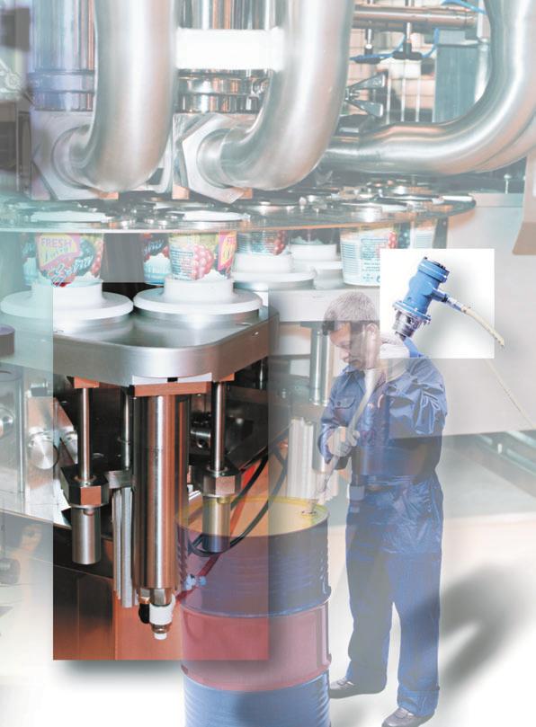
2 Atlas Copco air motors Leading the industry in development and innovation. Offering a comprehensive range of standard air motors. A premier supplier of air motors engineered to meet customer requirements. Delivering orders, on time, to customer schedules. Offering a truly world-wide service. Atlas Copco air motors the natural choice for design engineers in the industry of today and tomorrow. Air motor features and characteristics Air motors are compact and lightweight. An air motor weighs only a quarter as much and occupies only one sixth of the space of an electric motor of equivalent output power. Air motors develop far more power relative to size and weight than most other motor types. Air motors can be stalled indefinitely without overheating or sustaining any other damage. They can be started and stopped repeatedly to an unlimited extent., speed and direction of rotation can be changed easily using simple control methodes. Output that inherently adjusts to match the applied load. Controllable over a wide speed range. Virtually unaffected by hostile environment. Smooth start-up to minimize shock loading on transmission components. Our air motors are available in explosion proofcertified versions, in compliance with the European Union s ATEX Directive on equipment for potentially explosive environments.
3


4 Additional information about air motors from Atlas Copco Selecting the right motor has never been easier! Only enter the required working point for the application and the most suitable motor will automatically be selected. For the selection you either use the web based Atlas Copco selection tool or the windows based selection CD. The pocket guide is for you who want to know more about air motors. In the pocket guide you find information about function, design, motor selection and installations. Use the Ordering No Air motor selection program, Ordering No: hour access Visit our web site and browse through our on-line catalogue. You ll find comprehensive technical information as well as details of accessories, spare parts and dimensional drawings. You can also subscribe to our news. ATLAS COPCO AIRMOTORS
5 Contents Introducing the air motor... Methods of modifying motor output... 7 Throttling Pressure regulation Using the catalogue... 7 Motor data, specification and performance curves Understanding the performance Curves Installation Motor selection Introduction to Atlas Copco air motors and gear units... LZB vane motors introduction... Shaft loading Mounting Connection Hose dimensions LZB vane motors: data, specification and performance curves... LZB... LZB R... LZB... LZB R... LZB LR... LZB... LZB R... LZB LR, LZB R LR... LZB high torque... LZB /R with brake... LZB... 0 LZB... LZB... Accessories for LZB motors... LZL vane motors introduction... Shaft loading Mounting Connection Hose dimensions LZL vane motors: data, specification and performance curves... LZL 0 LZL LZL LZL vane motor/gear unit combinations... 0 Helical gear units type HG Worm gear units type BS Shaft loading Calculating sprocket or gearwheel dimensions Operating speed Mounting Temperature LZL air motors: with helical gear units data, specification and performance curves... LZL 0... LZL... LZL... LZL... LZL air motors: with worm gear units data, specification and performance curves... LZL 0... LZL... LZL... Choosing your motor The Working Point Atlas Copco airmotor selection guide Starting torque and stall torque Accelerating a load to speed Shaft loading Silencing Temperature Hostile environments Atlas Copco air motor selection program Installing your air motor... 7 Airlines Recommended hose connectors Air preparation Lubrication Control valves for air motors Installation examples ATLAS COPCO AIRMOTORS
6 Introducing the air motor The air motor is one of the toughest and most versatile power units available to today s design engineer. It is easy to control over a wide speed range, and it produces maximum torque where it is often most needed at start up. It should be noted that all vane air motors produce a variable starting torque, due to the position of the vanes in the motor when it is started. The variation differs between motor types and must be checked on an individual basis. The power that an air motor produces is a function of torque and speed. All ungoverned air motors produce the same characteristic power curve, with maximum power occurring at around 0% of the free speed. The torque produced at this point is often referred to as torque at maximum output. The performance curves for an ungoverned air motor operating at a constant air pressure are illustrated in figure. The performance of an air motor is dependant on the inlet pressure. At a constant inlet pressure, ungoverned air motors exhibit the characteristic linear output torque/speed relationship. Figure. [] Stall torque [] Min starting torque Speed [] Figure Speed [] Figure However, by simply regulating the air supply, using the techniques of throttling or pressure regulation, the output of an air motor can be easily modified. The use of gear units Air motors operate at high speed and, although they can be controlled over a wide speed range, the output characteristics are not always suitable for the application. To achieve the required output an appropriate gear unit can be selected. The ability to change the output by use of a gear unit is illustrated in figure. The free speed and torque can be regulated down to 0% for an LZB air motor. The free speed for an LZL can be regulated down to % and the torque can be regulated down to %. The shaded areas in figure illustrate this. [0%] 0 [0%] 0 [] 0 0 : : : 0 0 LZB Speed [0%] 0 0 LZL Speed [0%] :, :, : = gear ratios Speed [] Figure Figure The planetary and helical gear units used by Atlas Copco have a high level of efficiency that can be assumed to be 0%. The power output remains virtually unchanged also when gears are used. Note. The above does not apply to worm drive gear units, which can have high frictional losses and, therefore, loss of power output. ATLAS COPCO AIRMOTORS
7 Methods of modifying motor output Throttling A throttle is usually fitted into the motor s inlet hose, although it can also be fitted into the exhaust hose. When it is desirable to maintain a high starting torque but reduce running speed throttling is the best method of modifying the motor s output, Figure. Notes on performance data The performance data stated in this catalogue is valid for an air supply pressure of. bar (9 psi), gauge. Air consumption values are for free air delivery (ie, the volume the consumed air would occupy if allowed to expand to atmospheric pressure). The direction of rotation for a motor is always stated looking from the back of the motor. Figure 7 illustrate clockwise rotation. [] Pressure regulation Speed [] Figure Figure 7 When using a pressure regulator it is mostly fitted into the motor s inlet hose. The use of pressure regulation is ideal when control of the stall torque is required and a high starting torque is not so important, Figure. Understanding the performance curves The output of an air motor is most clearly seen from its performance curves Figure. For each motor/gear unit the power, torque and air consumption are shown as a function of speed. [%] 0 Operating pressure 7 bar bar bar bar bar The diagrams shown apply to an inlet pressure of. bar, to calculate performance at other pressures refer to page 70 in this catalogue. Motor selection Guidelines on motor selection are given on page 70 in this catalogue Choosing Your Motor. 0 Speed [%] Using the catalogue Motor data, specification and performance curves Figure For each Atlas Copco motor/gear unit combination the following information is presented in this catalogue.. Tabular Data Summary of main performance parameters.. Dimensional drawings.. Performance curves. [] [] Max output at max output Installation Air cons. [] Air. cons. Speed [] Note. The starting torque produced by an air motor is variable and depends on vane position. These diagrams do not indicate the starting torque this can be obtained from data tables, where the minimum value is shown. Figure General installation recommendations are given on page 7. Details specific to a motor are shown in the section relevant to that motor type. ATLAS COPCO AIRMOTORS 7


8 Introduction to Atlas Copco air motors and gear units LZB Vane motors 0. to. Type LZB Atlas Copco vane motors are compact in design, light in weight, and available with a host of different gear ratios to meet a variety of speed and torque requirements. They are particularly suited to be built into hand held machines, or indeed any industrial equipment. Planetary gear units Atlas Copco planetary gear units are particularly suited for use with LZB vane motors. The gear and motor components can be accommodated within a single, extremely compact housing where they provide high torque capacity for their size and exceptional efficiency, Figure. Stainless steel air motors Atlas Copco s stainless steel motors enlarge the field of applications to areas where the environment is corrosive. This can be in the food processing industries where corroding detergents are used or in the chemical industry where the atmosphere as such is corrosive. Atlas Copco s stainless steel motors have a clean design. Their smooth surfaces are cylindrical with no pockets where dirt can collect. The motors are easy to clean. The motors have double seals in Viton at the shaft end to prevent water from entering the gears. Explosion proof Our air motors are available in explosion proof certified versions, in compliance with the European Union.s ATEX Directive on equipment for potentially explosive environments. Figure Ex-Certified air motors are ideal in hazardous environments, where sparks or high outer temperatures might otherwise ignite explosive gases, vapour or dust. ATLAS COPCO AIRMOTORS

9 Lubrication free air motors Atlas Copco s lubrication free air motors are equipped with low-friction vanes, sealed bearings and vented cylinder plates. Since they release no lubricants into the air, they offer a viable drive solution for sensitive processes and hygienic environments where oil contamination would be at best a problem and, at worst, a catastrophe. LZL Vane motors. to, Type LZL Atlas Copco vane motors have been designed to offer outstanding starting and low speed performance. These general purpose motors are powerful, rugged and hard wearing, Figure. LZB high torque low speed air motors Accomplishing high torques generally calls for very large motors with correspondingly high air consumption. The LZB high torque/low speed air motors are based on the combination of LZB, the work horse in Atlas Copco s air motor program, and the gears used in the large LZB - motors. This gives a compact motor/gear package. The gears are dimensioned to stand being loaded at full stall torque indefinitely. Competing low speed air motors often have to limit their output torques to prevent gear breakage. Figure LZB LR and LR low speed airmotors When there is a need for low speed only, the LR motors offer a complete and low price solution compared to the high torque LZB airmotors. Helical gear units Atlas Copco helical gear units are normally fitted to Type LZL vane motors. Standard units are highly efficient, providing speeds of 00 down to at torques of up to 00. The gear unit is flange-coupled to the motor and the shafts are joined by a flexible coupling, Figure. Motors with brake The most popular vane motors, LZB, are available with parking brake. This brake is located between the motor and the gear. It is a disc brake that is spring activated when the motor is not running. When the motor is started the brake is released by a built in pneumatic piston. The brake is used when it is important that the output shaft must not turn when the motor isn t running and a torque is applied on the shaft Worm gear units Figure The LZL vane motors can also be supplied with worm gear units. In this configuration, they will deliver speeds of 00 down to at torques of up to 70. Worm gear units have a selfbraking action that can be beneficial in certain applications. The worm gear unit is flange-coupled to the motor and the shafts are linked by a flexible coupling, Figure. A: Clockwise rotation AR: Reversible AV: Anti-clockwise rotation L: Lubrication free LB: With brake module LR: Low speed R: Stainless steel RL: Stainless steel, lubrication free RLB: Stainless steel, with brake module RLR: Stainless steel, low speed Table illustrates what features the letters in the motor designation stands for. Table Figure ATLAS COPCO AIRMOTORS 9

10
11
12 LZB Vane motors Introduction LZB vane motors are designed to provide high performance and high standards of reliability. Typically, they are characterized by a high power output and small physical size, Figure. Fr (N ) Figure Fa (N ) The design of the motor is chosen to be long and slim. This gives a number of advantages like a high power to volume ratio, a low air consumption and long vane life. All motors utilise five vanes, which are supplied with vane air, to ensure excellent starting and low speed performance. Multi-step planetary gears are used to meet the torque and speed requirements of the application, offering high efficiency with compact dimensions. Shaft loading e thread g thread Cylindric shaft Fr A Fa Figure The maximum allowable loads on a given motor s output shaft are illustrated in Figure. The relevant load curve code for a motor is stated in the data tables for each specific motor designation, under the Shaft load code column. These values have been calculated for shaft and bearing working lives of million turns. To achieve a working life of 0 million turns, the loading factor must be halved. Fr (N) 00 0 Fr (max 00 N) 00 Threaded shaft Fa Fa (N) Curva d Curva c Curva b Curva a A = mm A = mm A = 9 mm A = mm Fr (N ) Fr (N) 000 Factor de conversión N = 0. lbf a thread b thread c thread Fa (N ) Curva h A = mm A = mm A = mm A = mm Fa (N) ATLAS COPCO AIRMOTORS

13 Mounting Type LZB vane motors may be mounted in any position. To facilitate this, flange and foot mounting are available for each motor, Figure. Reversible Motor The compressed air supply should be connected to the inlet that gives the desired direction of rotation, Figure. The inlet not in use functions as an additional outlet: it must not be plugged. Foot Connection Flange Figure Non-Reversible Motor When the compressed air supply is connected to the inlet, the direction of rotation will be as shown in Figure 7. If the exhaust air is to be piped away, a hose should be connected to the exhaust outlet. (EXH). Certain models have a third outlet, which can be plugged without affecting the performance of the motor. Clockwise rotation Figure Hose dimensions Information on hose dimensions recommended for use with type LZB air motors is detailed in Table. These dimensions are valid for hose lengths up to m. If lengths above that are used, choose a one size larger hose. Anti-clockwise rotation Figure 7 Hose size up to m length. Inlet Exhaust Inlet Exhaust hose Exhaust hose connection connection hose diameter diameter Motor thread thread diameter (Non-reversible) (Reversible) Type (BSP) (mm) (mm) (mm) (mm) LZB /" /".0.0. LZB /" /"..0.0 LZB /" /" LZB /" /" LZB /" /".0.0 LZB /" /".0.0 Table ATLAS COPCO AIRMOTORS
. Data at air pressure. bar (9psi) Ordering No. Speed Min Air cons.")
14 Vanemotor LZB Lubrication free versions LZB L hp For EX certification according to the ATEX directive (Ex II G T IIC D C) use Ordering No (book as one delivery together with motor). Data at air pressure. bar (9psi) Ordering No. Speed Min Air cons. Max at max at max starting Free at max Shaft Type ) Keyed Threaded Type Keyed Threaded output output output torque speed output Weight loading Shaft Shaft Shaft Shaft hp Ibf.ft Ibf.ft cfm kg Ib code ) Standard Lubrication free LZB - - LZB L - - Clockwise rotation A A a A0-0 0 A a A A a A A a A A a LZB - - LZB L - - Anti-clockwise rotation AV AV a AV0-0 AV a AV09-0 AV a AV0-0 AV a AV AV a LZB - - LZB L - - Reversible AR- 0 0 AR a AR0-0 9 AR a AR0-0 7 AR a AR00-0 AR a AR00-0 AR a ) Suffix. - = Keyed Shaft - = Threaded Shaft. ) For Shaft loading curves, see page. NOTE: The lubrication free motors have 9% of shown free speed Dimensions (mm) Keyed shaft (-) Threaded shaft (-) Non-Reversible Reversible *) +9. mm for LZB A0, A007, AR00, AR00, AV 0, AV 007 Optional Mountings Foot Ordering No Flange Ordering No. 0 0 ATLAS COPCO AIRMOTORS Optional accessories page.
15 LZB Performance curves at air pressure. bar (9psi) Non-Reversible LZB A LZB A LZB A LZB A LZB A Reversible 0. LZB AR 0. LZB AR LZB AR LZB AR LZB AR00 [] [] Max output Air cons. [] Conversion factors*) =. hp = 0.7 Ibf - ft =. cfm at max output Air. cons. hp = 0.7 Ibf-ft =. cfm = *) For more details, see page 7. Speed [] For information about performance curves, see page 7 ATLAS COPCO AIRMOTORS
16 Vanemotor LZB R Lubrication free versions LZB RL hp For EX certification according to the ATEX directive (Ex II G T IIC D C) use Ordering No (book as one delivery together with motor). The material used in the back head, casing and front part is stainless steel with the designation: ISO /XIII Type 7, SS, DIN 70 XCrNiS. The material used in the outgoing shaft and gear rim has the designation: ISO /XIII Type 9b, SS, DIN 70 XCrNi7. Data at air pressure. bar (9psi) Max Speed at max Min starting Designation output at max output torque Free Air cons. at Weight Shaft Designation Ordering Lubrication Ordering output speed max output loading Lubricated No. free No. hp Ibf.ft Ibf.ft cfm kg Ib code ) LZB R - LZB RL - Clockwise rotation A A a A0-0 A a A09-0 A a A0-0 A a A007-0 A a LZB R - LZB RL - Reversible AR- 0 9 AR a AR0-0 7 AR a AR0-0 7 AR a AR00-0 AR a AR AR ) For Shaft loading curves, see page. NOTE: The lubrication free motors have 9% of shown free speed a Dimensions (mm) Conversion factor mm = 0.0 inch * Non-Reversible Reversible h7 7,,* 7,9,,,9, øh ø7 7,9 EXH BSP / 7,9 EXH BSP / *) +9. mm for LZB R A0, A007, AR00, AR00 R, 0 9, ø0h7 7 0 Optional Mountings Foot Ordering No Optional Mountings Flange Ordering No M,,, ø, ATLAS COPCO AIRMOTORS Optional accessories page.
17 LZB R Performance curves at air pressure. bar (9psi) Non-Reversible LZB R A LZB R A LZB R A LZB R A LZB R A Reversible LZB R AR 0. LZB R AR0 0. LZB R AR LZB R AR00 LZB R AR [] [] Max output Air cons. [] Air. cons. Conversion factors*) =. hp = 0.7 Ibf - ft =. cfm at max output hp = 0.7 Ibf-ft =. cfm = 0.7 Speed [] *) For more details, see page 7. For information about performance curves, see page 7 ATLAS COPCO AIRMOTORS 7
 Ordering No. Speed Min Air cons.")
18 Vanemotor LZB Lubrication free versions LZB L hp For EX certification according to the ATEX directive (Ex II G T IIC D C) use Ordering No (book as one delivery together with motor). Data at air pressure. bar (9psi) Ordering No. Speed Min Air cons. Max at max at max starting Free at max Shaft Type ) Keyed Threaded Type Keyed Threaded output output output torque speed output Weight loading Shaft Shaft Shaft Shaft hp Ibf.ft Ibf.ft cfm kg Ib code ) Standard Lubrication free LZB - - LZB L - - Clockwise rotation A A b A A b A0-0 0 A b A0-0 0 A b A A b A A b A A b LZB - - LZB L - - Reversible AR- 0 AR b AR0-0 7 AR b AR0-0 AR b AR0-0 9 AR b AR AR b AR AR b AR00-0 AR ) Suffix. - = Keyed Shaft - = Threaded Shaft. ) For Shaft loading curves, see page b NOTE: The lubrication free motors have 9% of shown free speed. Dimensions (mm) Keyed shaft (-) Threaded shaft (-) Reversible for Optional Mountings Foot Ordering No. Non-Reversible Optional Mountings Foot Ordering No. with holes without holes Optional accessories page. ATLAS COPCO AIRMOTORS
19 LZB, LZB R Performance curves at air pressure. bar (9psi) Non-Reversible LZB A LZB A09 LZB A LZB A0 LZB A0 LZB A LZB A LZB AR 0. Reversible LZB AR0 0. LZB AR LZB AR LZB AR LZB AR LZB AR [] [] Max output Air cons. [] Air. cons. Conversion factors*) =. hp = 0.7 Ibf - ft =. cfm at max output hp = 0.7 Ibf-ft =. cfm = Speed [] *) For more details, see page 7. For information about performance curves, see page 7 ATLAS COPCO AIRMOTORS 9
20 Stainless steel vane motors LZB R Lubrication free versions LZB RL hp For EX certification according to the ATEX directive (Ex II G T IIC D C) use Ordering No (book as one delivery together with motor). The material used in the back head, casing and front part is stainless steel with the designation: ISO /XIII Type 7, SS, DIN 70 XCrNiS. The material used in the outgoing shaft and gear rim has the designation: ISO /XIII Type 9b, SS, DIN 70 XCrNi7. Data at air pressure. bar (9psi) Speed Min Air cons. Designation at max at max starting Free at max Weight Shaft Designation Ordering Lubrication Ordering Max output output output torque speed output loading Lubricated No. free No. hp Ibf.ft Ibf.ft cfm kg Ib code ) LZB R LZB RL Clockwise rotation A A b A09-07 A b A0-07 A b A A b A A b A00-07 A b A00-07 A b LZB R LZB RL Reversible AR AR b AR0-0 AR b AR AR b AR0-0 AR b AR00-0 AR b AR AR b AR AR b ) For Shaft loading curves, see page. Performance curves are given on page 9. NOTE: The lubrication free motors have 9% of shown free speed. Dimensions (mm) Keyed shaft (-) Non-Reversible Reversible Optional Mounting Foot Ordering No * +. mm for LZB R A0 LZB R AR00 LZB R A00 LZB R AR00 LZB R A00 LZB R AR00 Optional Mounting Flange Ordering No ATLAS COPCO AIRMOTORS Optional accessories page.
. Within their working range these motors have a very steep torque curve. Speed and air consumption is relatively constant regardless of the load.")
21 Vane motors LZB LR, LZB R LR Low speed reversible Maximum permitted torque 9 (. lbf.ft). For EX certification according to the ATEX directive (Ex II G T IIC D C) use Ordering No (book as one delivery together with motor). Within their working range these motors have a very steep torque curve. Speed and air consumption is relatively constant regardless of the load. Data at air pressure. bar (9psi) Free Air Shaft Designation Ordering Designation Ordering speed consumtion Weight loading Lubricated No. Lubrication free No. cfm kg lb code ) LZB LR0-0 LZB L LR b LZB LR LZB L LR b Stainless steel LZB R LR0-0 LZB RL LR b LZB R LR- 0 LZB RL LR b ) For Shaft loading curves, see page. Dimensions LZB RL (mm) Optional Mountings Foot for LZB LR Ordering No *) + mm for LZB LR. Reversible Flange for LZB LR Ordering No. 09 Dimensions LZB R LR (mm) Keyed shaft (-) Conversion factor mm = 0.0 inch Reversible Optional Mounting Foot Ordering No * +. mm for LZB R LR Optional Mounting Flange Ordering No Optional accessories page. ATLAS COPCO AIRMOTORS
 Ordering No. Speed Min Air cons.")
22 Vane motors LZB Lubrication free versions LZB L 9 0. hp For EX certification according to the ATEX directive (Ex II G T IIC D C) use Ordering No (book as one delivery together with motor). Data at air pressure. bar (9psi) Ordering No. Speed Min Air cons. Max at max at max starting Free at max Shaft Type ) Keyed Threaded Type Keyed Threaded output output output torque speed output Weight loading Shaft Shaft Shaft Shaft hp Ibf.ft Ibf.ft cfm kg Ib code ) Standard Lubrication free LZB - - LZB L - - Clockwise rotation A A c A A c A A c A A c A A c A A c A A c A A d LZB - - LZB L - - Reversible AR AR c AR0-00 AR c AR0-00 AR c AR09-00 AR c AR AR c AR AR c AR AR c AR AR ) Suffix. - = Keyed Shaft - = Threaded Shaft. ) For Shaft loading curves, see page d NOTE: The lubrication free motors have 9% of shown free speed. Dimensions (mm) Keyed shaft (-) Threaded shaft (-) Reversible for Non-Reversible LZB A000- LZB AR00- Optional Mounting Foot Ordering No Optional Mounting Flange Ordering No. 07 with holes 07 0 without holes ATLAS COPCO AIRMOTORS Optional accessories page.
23 LZB, LZB R Performance curves at air pressure. bar (9psi) Non-Reversible LZB A LZB A0 LZB A LZB A0 LZB A0 LZB A LZB A00 0. LZB A000 [] [] Air cons. [] Max output Air. cons at max output Speed [] Reversible LZB AR LZB AR0 LZB AR LZB AR09 LZB AR009 LZB AR LZB AR00 0. LZB AR00 Conversion factors*) =. hp = 0.7 Ibf - ft =. cfm hp = 0.7 Ibf-ft =. cfm = 0.7 *) For more details, see page ATLAS COPCO AIRMOTORS
24 Stainless steel vane motors LZB R Lubrication free versions LZB RL 9 0. hp For EX certification according to the ATEX directive (Ex II G T IIC D C) use Ordering No (book as one delivery together with motor). The material used in the back head, casing and front part is stainless steel with the designation: ISO /XIII Type 7, SS, DIN 70 XCrNiS. The material used in the outgoing shaft and gear rim has the designation: ISO /XIII Type 9b, SS, DIN 70 XCrNi7. Data at air pressure. bar (9psi) Speed Min Air cons. Designation at max at max starting Free at max Shaft Designation Ordering Lubrication Ordering Max output output output torque speed output Weight loading Lubricated No. free No. hp Ibf.ft Ibf.ft cfm kg Ib code ) LZB R LZB RL Clockwise rotation A A c A0-07 A c A0-07 A c A0-07 A c A0-07 A c A A c A A c LZB R LZB RL Reversible AR AR c AR0-07 AR c AR AR c AR AR c AR AR c AR AR c AR00-0 AR00- ) For Shaft loading curves, see page c Performance curves are given on page. NOTE: The lubrication free motors have 9% of shown free speed. Dimensions (mm) Conversion factor mm = 0.0 inch Keyed shaft (-) Non-Reversible Reversible Optional Mounting Foot Ordering No * +. mm for LZB R A0 LZB R AR009 LZB R A00 LZB R AR00 LZB R A00 LZB R AR00 Optional Mounting Flange Ordering No ATLAS COPCO AIRMOTORS Optional accessories page.
. For applications where low speed and high torque are required the LZB high torque/low speed motors should be considered, see page.")
 Free Air Shaft Designation Ordering Designation Ordering speed consumtion Weight loading Lubricated No. Lubrication free No. cfm kg lb code ) LZB LR0-0 LZB L LR0-00 0 9.9..7 c LZB LR- 0 LZB L LR- 00 9.")
25 Vane motor LZB LR, LZB R LR Low speed reversible Maximum permitted torque (. lbf.ft) For EX certification according to the ATEX directive (Ex II G T IIC D C) use Ordering No (book as one delivery together with motor). For applications where low speed and high torque are required the LZB high torque/low speed motors should be considered, see page. Within their working range these motors have a very steep torque curve. Speed and air consumption is relatively constant regardless of the load. Data at air pressure. bar (9psi) Free Air Shaft Designation Ordering Designation Ordering speed consumtion Weight loading Lubricated No. Lubrication free No. cfm kg lb code ) LZB LR0-0 LZB L LR c LZB LR- 0 LZB L LR c LZB LR- 0 LZB L LR c LZB LR LZB L LR c Stainless steel LZB R LR0-0 0 LZB RL LR c LZB R LR- 0 LZB RL LR c LZB R LR- 0 LZB RL LR c LZB R LR- 0 ) For Shaft loading curves, see page. LZB RL LR c Dimensions LZB LR (mm) Reversible * +. mm for LZB LR, LR Optional Mounting Foot for LZB LR +7 mm for LZB LR Ordering No Flange for LZB LR Ordering No. 07 Dimensions LZB R LR (mm) Keyed shaft (-) Conversion factor mm = 0.0 inch Reversible * +. mm for LZB R LR LZB R LR +9 mm for LZB R LR Optional Mounting Foot Ordering No Optional Mounting Flange Ordering No Optional accessories page. ATLAS COPCO AIRMOTORS
. Data at air pressure. bar (9psi) Speed Min Air cons.")
 LZB - LZB L - Clockwise rotation A00-0 09 A00-0 07 0.9 9. 7... g A00-0 7 A00-0 0.9 77 90. 7... g A00-0 A00-0 0.9 9 7. 7... g A000-0 A000-0 0.9 79 7 7. 7... g A0007-0 A0007-0 9 0.")
 For Shaft loading curves, see page.")
26 High torque LZB vane motors Lubrication free versions LZB L 0.9 hp For EX certification according to the ATEX directive (Ex II G T IIC D C) use Ordering No (book as one delivery together with motor). Data at air pressure. bar (9psi) Speed Min Air cons. at max at max starting Free at max Shaft Designation Ordering Designation Ordering Max output output output torque speed output Weight loading Lubricated No. Lubrication free No hp Ibf.ft Ibf.ft cfm kg lb code ) LZB - LZB L - Clockwise rotation A A g A A g A00-0 A g A000-0 A g A A g A000-0 A h A000-0 A h A A h A000-0 A h LZB - LZB L - Reversible AR AR g AR00-0 AR g AR000-0 AR g AR000-0 AR g AR AR g AR AR h AR000-0 AR h AR AR h AR000-0 AR000- ) For Shaft loading curves, see page h NOTE: The lubrication free motors have 9% of shown free speed. Dimensions (mm) Conversion factor mm = 0.0 inch Lubricated Lubrication free Non reversible LZB A00- LZB L A00- LZB A00- LZB L A00- LZB A00- LZB L A00- LZB A000- LZB L A000- LZB A0007- LZB L A0007- Reversible LZB AR00- LZB L AR00- LZB AR00- LZB L AR00- LZB AR000- LZB L AR000- LZB AR000- LZB L AR000- LZB AR000- LZB L AR000- All versions Reversible Non-Reversible Optional Mountings holes mm deep Flange Ordering No Lubricated Lubrication free Non reversible LZB A000- LZB L A000- LZB A000- LZB L A000- LZB A000- LZB L A000- LZB A000- LZB L A000- Foot Ordering No ATLAS COPCO AIRMOTORS Reversible LZB AR000- LZB L AR000- LZB AR000- LZB L AR000- LZB AR000- LZB L AR000- LZB AR000- LZB L AR000- Optional accessories page.
27 LZB high torque motors Performance curves at. bar (9 psi) Non-Reversible LZB A00 LZB A00 LZB A LZB A000 LZB A0007 LZB A LZB A LZB A LZB A Reversible 0. LZB AR00 0. LZB AR00 0. LZB AR LZB AR LZB AR LZB AR LZB AR LZB AR LZB AR For information about performance curves, see page 7 Conversion factors see page. ATLAS COPCO AIRMOTORS 7
 use Ordering No. 9 00 (book as one delivery together with motor). Data at air pressure. bar (9psi) Speed Air cons.")
28 Vane motors LZB LB, LZB RLB with brake module Lubrication free and reversible hp Braking torque from 0.. The brake is activated by spring force and released by air pressure. For EX certification according to the ATEX directive (Ex II G T IIC D C) use Ordering No (book as one delivery together with motor). Data at air pressure. bar (9psi) Speed Air cons. at max at max Min start Braking Free at max Shaft Designation Ordering Max output output output torque torque speed output Weight loading Lubrication free No. hp lbt.ft lbt.ft lbt.ft cfm kg lb code ) LZB LB AR c LZB LB AR c LZB LB AR c LZB LB AR c LZB LB AR c LZB LB AR c LZB LB AR c LZB LB AR , d LZB LB AR g LZB LB AR g LZB LB AR g LZB LB AR g LZB LB AR g LZB LB AR h LZB LB AR h LZB LB AR h LZB LB AR h Stainless steel LZB RLB AR c LZB RLB AR c LZB RLB AR c LZB RLB AR c LZB RLB AR c LZB RLB AR c LZB RLB AR ) For Shaft loading curves, see page c The brake needs minimum bar to release. Performance curves are given on page and 7. Dimensions (mm) Conversion factor mm = 0.0 inch LZB LB AR- LZB LB AR0- LZB LB AR0- LZB LB AR09- * +. mm for LZB LB AR009- LZB LB AR00- LZB LB AR00- * + mm for LZB RLB AR- LZB RLB AR0- LZB RLB AR0- LZB RLB AR09- * +. mm for LZB RLB AR009- LZB RLB AR00- LZB RLB AR00- All versions LZB LB, Flange Ordering No. 07 LZB RLB, Ordering No Foot ordering No Stainless foot Ordering No ATLAS COPCO AIRMOTORS Optional accessories page.
29 Dimensions (mm) Conversion factor mm = 0.0 inch LZB LB AR00- Dimensions (mm) Conversion factor mm = 0.0 inch LZB LB AR00- LZB LB AR00- LZB LB AR000- LZB LB AR000- LZB LB AR000-0 Foot Ordering No Flange Ordering No Dimensions (mm) Conversion factor mm = 0.0 inch LZB LB AR000- LZB LB AR000- LZB LB AR000- LZB LB AR000- M holes mm DEEP ATLAS COPCO AIRMOTORS 9
30 Vane motor LZB hp For EX certification according to the ATEX directive (Ex II G T IIC D C) use Ordering No (book as one delivery together with motor). For optional lubrication free vanes and/or threaded shafts see page Data at air pressure. bar (9psi) Speed Min Air cons. Max at max at max starting Free at max Shaft Type Ordering No. output output output torque speed output Weight loading hp lbf.ft lbf.ft cfm kg lb code ) Clockwise rotation LZB A e LZB A e LZB A e LZB A e LZB A e LZB A e LZB A e LZB A g LZB A g LZB A g LZB A h LZB A h Speed Min Air cons. Max at max at max starting Free at max Shaft Type Ordering No. output output output torque speed output Weight loading hp lbf.ft lbf.ft cfm kg lb code ) Anti-clockwise rotation LZB AV e LZB AV e LZB AV e LZB AV e LZB AV e LZB AV e LZB AV e LZB AV g LZB AV g LZB AV g LZB AV h LZB AV h Speed Min Air cons. Max at max at max starting Free at max Shaft Type Ordering No. output output output torque speed output Weight loading hp lbf.ft lbf.ft cfm kg lb code ) Reversible LZB AR e LZB AR e LZB AR e LZB AR e LZB AR e LZB AR e LZB AR e LZB AR g LZB AR g LZB AR g LZB AR h LZB AR h ) For Shaft loading curves, see page. 0 ATLAS COPCO AIRMOTORS
31 Dimensions (mm) Conversion factor mm = 0.0 inch Non reversible LZB A0- LZB A0- LZB A00- LZB A0- LZB A0- LZB A0- LZB A00- LZB AV0- LZB AV0- LZB AV00- LZB AV0- LZB AV0- LZB AV0- LZB AV00- Reversible LZB AR70- LZB AR00- LZB AR00- LZB AR0- LZB AR0- LZB AR007- LZB AR00- Optional Mountings Reversible Non-Reversible All versions Flange Ordering No Foot Ordering No Non reversible LZB A000- LZB A00- LZB A00- LZB AV000- LZB AV00- LZB AV00- Reversible LZB AR00- LZB AR00- LZB AR00- Optional Mountings Flange Ordering No Foot Ordering No Non reversible LZB A000- LZB A000- LZB AV000- LZB AV000- Reversible LZB AR000- LZB AR000- holes mm deep ATLAS COPCO AIRMOTORS
32 LZB Performance curves at air pressure. bar (9psi) Non-Reversible 0.7 LZB A0 0.7 LZB A0 0.7 LZB A LZB A0 LZB A0 LZB A LZB A00 LZB A000 LZB A LZB A00 LZB A000 LZB A [] [] Max output Air cons. [] Air. cons. at max output Speed [] For information about performance curves, see page 7 ATLAS COPCO AIRMOTORS
33 LZB Performance curves at air pressure. bar (9psi) Reversible LZB AR70. LZB AR00 LZB AR LZB AR0 LZB AR0 LZB AR LZB AR00 LZB AR00 LZB AR LZB AR00 LZB AR LZB AR [] [] Max output Air cons. [] Air. cons. Conversion factors*) =. hp = 0.7 Ibf - ft =. cfm at max output hp = 0.7 Ibf-ft =. cfm = 0.7 Speed [] *) For more details, see page 7. For information about performance curves, see page 7 ATLAS COPCO AIRMOTORS
34 Vane motor LZB hp For EX certification according to the ATEX directive (Ex II G T IIC D C) use Ordering No (book as one delivery together with motor). For optional lubrication free vanes see page Data at air pressure. bar (9psi) Speed Min Air cons. Ordering No. Max at max at max starting Free at max Shaft Type ) Keyed Threaded output output output torque speed output Weight loading Shaft Shaft hp lbf.ft lbf.ft cfm kg lb code ) LZB - - Clockwise rotation A e A e A e A e A e A e A e A g A g A g A h A h Speed Min Air cons. Max at max at max starting Free at max Shaft Type Ordering No. output output output torque speed output Weight loading hp lbf.ft lbf.ft cfm kg lb code ) Anti-clockwise rotation LZB AV e LZB AV e LZB AV e LZB AV e LZB AV e LZB AV e LZB AV e LZB AV g LZB AV g LZB AV g LZB AV h LZB AV h Speed Min Air cons. Max at max at max starting Free at max Shaft Type Ordering No. output output output torque speed output Weight loading hp lbf.ft lbf.ft cfm kg lb code ) Reversible LZB AR e LZB AR e LZB AR e LZB AR e LZB AR e LZB AR e LZB AR e LZB AR g LZB AR g LZB AR g LZB AR h LZB AR h ) For Shaft loading curves, see page. ) Suffix. - = Keyed Shaft - = Threaded Shaft. ATLAS COPCO AIRMOTORS
35 Dimensions (mm) Conversion factor mm = 0.0 inch Non reversible LZB A0-/ LZB A0-/ LZB A00-/ LZB A0-/ LZB A0-/ LZB A0-/ LZB A00-/ LZB AV0- LZB AV0- LZB AV00- LZB AV0- LZB AV0- LZB AV0- LZB AV00- ø7 / - UNF Threaded shaft 9. Keyed shaft Optional Mountings Reversible Reversible LZB AR70- LZB AR00- LZB AR00- LZB AR0- LZB AR0- LZB AR007- LZB AR00- Non-Reversible Flange Ordering No Foot Ordering No All versions Non reversible LZB A000-/ LZB A00-/ LZB A00-/ LZB AV000- LZB AV00- LZB AV00- Reversible LZB AR00- LZB AR00- LZB AR00- ø0 / - UNF Threaded shaft Keyed shaft Optional Mountings Flange Ordering No Foot Ordering No Non reversible LZB A000- LZB A000- LZB AV000- LZB AV000- Reversible LZB AR000- LZB AR000- holes mm deep ATLAS COPCO AIRMOTORS
36 LZB Performance curves at air pressure. bar (9psi) Non-Reversible LZB A0 LZB A0 LZB A LZB A0 LZB A0 LZB A LZB A00 LZB A000 0 LZB A LZB A00 0 LZB A000 LZB A [] [] Max output Air cons. [] Air. cons. at max output Speed [] For information about performance curves, see page 7 ATLAS COPCO AIRMOTORS
37 LZB Performance curves at air pressure. bar (9psi) Reversible LZB AR LZB AR00 LZB AR LZB AR LZB AR LZB AR LZB AR00 LZB AR00 LZB AR LZB AR00 LZB AR000 0 LZB AR [] [] Max output Air cons. [] Air. cons. at max output Speed [] For information about performance curves, see page 7 ATLAS COPCO AIRMOTORS 7
38 Vane motor LZB hp For EX certification according to the ATEX directive (Ex II G T IIC D C) use Ordering No (book as one delivery together with motor). For optional lubrication free vanes and/or threaded shafts see page Data at air pressure. bar (9psi) Speed Min Air cons. Max at max at max starting Free at max Shaft Type Ordering No. output output output torque speed output Weight loading hp lbf.ft lbf.ft cfm kg lb code ) Clockwise rotation LZB A g LZB A g LZB A g LZB A g LZB A g LZB A g LZB A g LZB A h LZB A h LZB A h Speed Min Air cons. Max at max at max starting Free at max Shaft Type Ordering No. output output output torque speed output Weight loading hp lbf.ft lbf.ft cfm kg lb code ) Anti-clockwise rotation LZB AV g LZB AV g LZB AV g LZB AV g LZB AV g LZB AV g LZB AV g LZB AV h LZB AV h LZB AV h Speed Min Air cons. Max at max at max starting Free at max Shaft Type Ordering No. output output output torque speed output Weight loading hp lbf.ft lbf.ft cfm kg lb code ) Reversible LZB AR g LZB AR g LZB AR g LZB AR g LZB AR g LZB AR g LZB AR g LZB AR h LZB AR h LZB AR h ) For Shaft loading curves, see page. ATLAS COPCO AIRMOTORS
39 Dimensions (mm) Conversion factor mm = 0.0 inch Non reversible LZB A0- LZB A00- LZB A00- LZB A0- LZB A0- LZB A007- LZB A00- LZB AV0- LZB AV00- LZB AV00- LZB AV0- LZB AV0- LZB AV007- LZB AV00- Reversible LZB AR0- LZB AR0- LZB AR0- LZB AR0- LZB AR00- LZB AR00- LZB AR00- Reversible Optional Mountings Non-Reversible All versions Flange Ordering No Foot Ordering No Non reversible LZB A00- LZB A007- LZB A00- LZB AV00- LZB AV007- LZB AV00- Reversible LZB AR00- LZB AR00- LZB AR0009- holes mm deep ATLAS COPCO AIRMOTORS 9
40 LZB Performance curves at air pressure. bar (9psi) Non-Reversible. LZB A0. LZB A00. LZB A LZB A0 LZB A0 0 LZB A LZB A00 LZB A00 LZB A LZB A [] [] Max output Air cons. [] Air. cons. at max output Speed [] For information about performance curves, see page 7 0 ATLAS COPCO AIRMOTORS
41 LZB Performance curves at air pressure. bar (9psi) Reversible LZB AR0. LZB AR0. LZB AR LZB AR0 LZB AR00 LZB AR LZB AR00 LZB AR00 LZB AR LZB AR [] [] Max output Air cons. [] Air. cons. Conversion factors*) =. hp = 0.7 Ibf - ft =. cfm at max output hp = 0.7 Ibf-ft =. cfm = 0.7 Speed [] *) For more details, see page 7. For information about performance curves, see page 7 ATLAS COPCO AIRMOTORS


42 Accessories for LZB air motors Key chuck and quick chuck for LZB /- Body Capacity Ordering No. Chuck type Mount diameter (mm) (mm) Key chuck /- UNF Key chuck /- UNF Key chuck /- UNF Quick chuck /- UNF Quick chuck /- UNF Quick chuck /- UNF Threaded shafts for re-building standard motors Motor Thread dimension Ordering No. LZB A0 /" UNF LZB A0 /" UNF LZB A00 /" UNF 0 0 LZB A0 /" UNF 0 0 LZB A0 /" UNF LZB A0 /" UNF LZB A00 /" UNF LZB A000 /" UNF LZB A00 /" UNF LZB A00 /" UNF LZB A0 /" UNF LZB A00 /" UNF LZB A00 /" UNF 0 07 LZB A0 /" UNF 0 07 LZB A0 /" UNF LZB A007 /" UNF LZB A00 /" UNF Collet chuck and collets for LZB /- mm Capacity in Ordering No. Collet holder cpl Collet Collet Collet Collet / Collet / Collet / 0 00 Collet / Collet / ATLAS COPCO AIRMOTORS


43 Lubrication free vane sets Motor Ordering No. LZB LZB LZB Silencers A B C Motor Sinter bronze LBB ECSB- LZB LZB LZB LZB LZB LZB Noise damp db(a) loss % 7 Note: The noise damp and power loss values are approximate. The ECSB silencer 0 has / and the 0 has threaded port. They need to be connected to the motor via tube or hose with suitable connections. The LBB silencer has / threaded port. LZB, and need to be connected via tube or hose with suitable connections. For LZB, and a bushing has to be used, Ordering No ATLAS COPCO AIRMOTORS
44

45
46 LZL Vane motors Introduction LZL vane motors are designed to give outstanding starting and low speed performance. This is achieved by using a six vane motor and by optimum vane/cylinder sealing obtained through a combination of vane air and interconnecting pins. Featuring only components, these motors are ruggedly constructed and offer a long service life. Type LZL vane motors are available in four sizes, offering outputs of.,.,. and, respectively. Typically these motors are characterized by: Reliable starting. High starting torque and good low speed characteristics. Wide speed and torque range. Sturdy, compact construction to withstand rough treatment. Inlet and outlet port restrictors permit free speed running. Long working life and easy servicing.. Six vanes for high starting torque.. Pins to force vanes out and provide starting reliability.. Cast iron housing.. Long life bearings.. Restriction at inlet and outlet ports. Figure 9 The general configuration and key design featurs of the Type LZL large vane motor are illustrated in Figure 9. ATLAS COPCO AIRMOTORS
47 Shaft loading The permitted radial and axial shaft extension loadings are illustrated in Figure. These values have been calculated for shaft and bearing working lives of at least,000 hours at a speed that gives maximum output. Mounting Type LZL vane motors may be mounted in any position. To facilitate this, a flange is integrated into the motor casing and a foot mounting is available for each motor variant. Clockwise rotation the position of these restrictors must be reversed. Reversing duty restrictor () must be replaced by a second restrictor of type (). The restrictor () must then be fitted into the inlet to the control valve. For further information refer to Installation Examples on page 7. It is permissable to remove these restrictors to increase motor output. However, the motor should not be run faster than max allowed speed (see data table). Connection Type LZL motors are supplied with internal restrictors in the connection ports. As illustrated in Figure, one is larger than the other. Anti-Clockwise rotation the smaller restrictor () is fitted in the inlet port and the larger restrictor () in the outlet port (as shown). Figure NON-REVERSIBLE DUTY REVERSIBLE DUTY Connection Inlet hose Exhaust hose Inlet hose Exhaust hose Motor thread diameter dimaeter diameter diameter type (BSP) (mm) (mm) (mm) (mm) LZL 0 /" LZL /" LZL " LZL /" Hose dimensions Table Information on hose dimensions recommended for use with type LZL air motors is detailed in Table. These dimensions are valid for hose lengths up to m. If lengths above that are used, choose a one size larger hose. Fa (N) Fr LZL LZL LZL LZL 0 A = mm A = mm A = mm A = mm Figure ATLAS COPCO AIRMOTORS 7
 Speed Min Max Air cons.")

 Air motor Measurements (mm) Conversion factor mm = 0.0 inch Type a b c d e f g LZL 0 7.")
48 LZL Vane motors hp For EX certification according to the ATEX directive (Ex II G T IIC D C) use Ordering No (book as one delivery together with motor). LZL is not available Ex certified. Data at air pressure. bar (9psi) Speed Min Max Air cons. Max at max at max starting Free allowed at max output output output torque speed speed output Weight Type Ordering No. hp lbf.ft lbf.ft cfm kg lb LZL Unrestricted* LZL Unrestricted* LZL Unrestricted* LZL Unrestricted* *) Unrestricted, the motors should not be run above max allowed speed Foot bracket LZL 0 LZL LZL Ordering No Foot bracket Measurements (mm) Air motor Measurements (mm) Conversion factor mm = 0.0 inch Type a b c d e f g LZL LZL LZL Type A B C D E F G H J K L M N O P R S T U LZL 0 70j j M BSP /".7. h9 LZL 7 9j j M BSP /".. h9 LZL j j M... 0 BSP " h7 LZL 0 0j j M,,, 0 9 BSP /" 70 h7 ATLAS COPCO AIRMOTORS
49 LZL Performance curves at air pressure. bar (9psi) LZL 0 LZL LZL LZL Performance with restrictors Performance without restrictors, (unrestricted) Conversion Factors*) =. hp = 0.7 Ibf - ft =. cfm hp = 0.7 Ibf-ft =. cfm = 0.7 *) For more details, see page 7. [] [] Max output Air cons. [] Air. cons. at max output Speed [] For information about performance curves, see page 7 ATLAS COPCO AIRMOTORS 9

50 LZL Vane motor/gear unit combinations Combined with helical or worm gear units, type LZL vane air motors can be used over a very wide torque and speed range. Models are nominally available with gear ratios that range from : to :, corresponding to a speed range of to and an output torque of up to 000. Helical gear units type HG. Helical gear units are available in -stage and -stage configurations. They deliver high efficiency levels and are available in wide choice of ratios, Figure. Shaft loading Motors with helical gear units The maximum allowable radial load on the output shaft of each gear unit, at the half way point on the shaft can be obtained from the data tables for each model. The maximum permitted axial load is 0% of the radial load. All units will accept 0% momentary overloads on above stated capacities Motors with worm gear units Worm gear units have individual output shafts and the allowable radial load is therefore different for each version. The maximum allowable radial load, at the half way point on the shaft, is stated in the worm gear data tables on page, and. If the load is applied at another point on the shaft, the allowable radial load can be calculated by multiplying the stated value by the factor indicated by Figure. The permitted axial load is 0% of the radial load.. 0, E / Figure E Figure Worm gear units type BS Worm gear units are smaller and lighter in operation than helical gear units. However, they offer lower levels of efficiency. Where the highest gear ratios are required, it should be noted that starting efficiency can be as low as 0%, Figure. A hollow shaft can be obtained by taking out the cylindrical output shaft for BS 0, BS and BS 7. Figure Note. Gear units with different reduction ratios can be supplied to special order. For comprehensive information on these versions, please contact your local Atlas Copco representative. 0 ATLAS COPCO AIRMOTORS

51 Calculating sprocket or gearwheel dimensions If it is intended to fit a sprocket, gearwheel or pulley onto the output shaft, the radial load generated when running must be within the permitted level. Motors with worm gear units Suggested mounting arrangements are illustrated in Figure 7. Figure shows how the units can be mounted if the mounting brackets are relocated. When the units are to be mounted vertically, the motor should point upwards. The following formula is used to calculate the minimum diameter of these components, to ensure the radial load does not exceed this limit. D min = x M x kt [m] F where M = load torque in F = permitted radial force halfway along the shaft extension kt = for sprocket. for gear wheel. for pulley Operating speed To avoid damage to seals the gear units should not be run continuously above the following speeds; The worm gears are available in different dispositions. Figure 7 Helical gear units Motor plus gear Max input speed LZL 0-HG 00 LZL 0-HG 00 LZL 0-HG 00 LZL -HG 00 LZL -HG 00 LZL -HG 00 LZL -HG 00 LZL -HG 00 LZL -HG 00 LZL -HG 00 LZL -HG 00 LZL -HG7 00 LZL -HG 00 LZL -HG 00 LZL -HG 00 LZL -HG 00 LZL -HG7 00 LZL -HG 00 LZL -HG9 00 Worm gear units Gear unit type Max input speed BS 0 00 BS 000 BS 7 00 BS 000 BS 000 The dispositions are achieved by turning the motor 0 and for BS 0, -, -7 by moving the attachment brackets. Temperature Figure Helical gear units can operate within an ambient temperature range of 0 C and + C. It is recommended that worm gear units are only operated within an ambient temperature range of 0 C and +0 C. If it is required to use a gear unit outside these temperature limites please consult with your local Atlas Copco representative. Mounting Motors with helical gear units These units can be supplied with two different types of mounting arrangement: Foot or Flange as illustrated in fig.. The type required must be specified when ordering.. Foot. Flange Mounting position Figure ATLAS COPCO AIRMOTORS
52 Air motor LZL 0 with helical gear units...7. hp Performance at. bar (9 psi) Speed Min Max Air cons. Max radial Max at max at max starting Free allowed at max load at max output output output torque speed speed output Weight output Designation Ordering No. Ratio hp lbf.ft lbf.ft cfm kg lb N LZL 0-HG-A LZL 0-HG-B Unrestricted* LZL 0-HG-A LZL 0-HG-B Unrestricted* LZL 0-HG-A LZL 0-HG-B Unrestricted* LZL 0-HG-A LZL 0-HG-B Unrestricted* LZL 0-HG-A LZL 0-HG-B Unrestricted* LZL 0-HG-A LZL 0-HG-B Unrestricted* LZL 0-HG-A LZL 0-HG-B Unrestricted* LZL 0-HG-A LZL 0-HG-B Unrestricted* LZL 0-HG-A LZL 0-HG-B Unrestricted* LZL 0-HG-A LZL 0-HG-B Unrestricted* LZL 0-HG-A LZL 0-HG-B Unrestricted*.., *) Unrestricted, the motors should not be run without load A = Foot mount B = Flange mount ATLAS COPCO AIRMOTORS
53 Air motor LZL 0 with helical gear units type HG Performance curves at air pressure. bar (9psi). LZL 0-HG-A/B-009. LZL 0-HG-A/B-0. LZL 0-HG-A/B LZL 0-HG-A/B-0. 0 LZL 0-HG-A/B-0. LZL 0-HG-A/B LZL 0-HG-A/B-0. LZL 0-HG-A/B LZL 0-HG-A/B LZL 0-HG-A/B-. LZL 0-HG-A/B Performance with restrictors Performance without restrictors, (unrestricted) Conversion Factors*) =. hp = 0.7 Ibf - ft =. cfm [] [] Max output Air cons. [] Air. cons. hp = 0.7 Ibf-ft =. cfm = 0.7 *) For more details, see page 7. at max output Speed [] For information about performance curves, see page 7 ATLAS COPCO AIRMOTORS

54 Air motor LZL with helical gear units...0. hp Performance at. bar (9 psi) Speed Min Max Air cons. Max radial Max at max at max starting Free allowed at max load at max output output output torque speed speed output Weight output Designation Ordering No. Ratio hp lbf.ft lbf.ft cfm kg lb N LZL -HG-A LZL -HG-B Unrestricted* LZL -HG-A LZL -HG-B Unrestricted* LZL -HG-A LZL -HG-B Unrestricted* LZL -HG-A LZL -HG-B Unrestricted* LZL -HG-A LZL -HG-B Unrestricted* LZL -HG-A LZL -HG-B Unrestricted* LZL -HG-A LZL -HG-B Unrestricted* LZL -HG-A LZL -HG-B Unrestricted* LZL -HG-A LZL -HG-B Unrestricted* LZL -HG-A LZL -HG-B Unrestricted* LZL -HG-A LZL -HG-B Unrestricted* *) Unrestricted, the motors should not be run without load A = Foot mount B = Flange mount ATLAS COPCO AIRMOTORS
55 Air motor LZL with helical gear units type HG Performance curves at air pressure. bar (9psi). LZL -HG-A/B-009. LZL -HG-A/B-0. LZL -HG-A/B LZL -HG-A/B-0. LZL -HG-A/B-0. LZL -HG-A/B LZL -HG-A/B-0. LZL -HG-A/B-07. LZL -HG-A/B LZL -HG-A/B-. LZL -HG-A/B Performance with restrictors Performance without restrictors, (unrestricted) Conversion Factors*) =. hp = 0.7 Ibf - ft =. cfm [] [] Max output Air cons. [] hp = 0.7 Ibf-ft =. cfm = 0.7 Air. cons. *) For more details, see page 7. at max output Speed [] For information about performance curves, see page 7 ATLAS COPCO AIRMOTORS
56 Air motor LZL with helical gear units..9.. hp Performance at. bar (9 psi) Speed Min Max Air cons. Max radial Max at max at max starting Free allowed at max load at max output output output torque speed speed output Weight output Designation Ordering No. Ratio hp lbf.ft lbf.ft cfm kg lb N LZL -HG-A LZL -HG-B Unrestricted* LZL -HG-A LZL -HG-B Unrestricted* LZL -HG-A LZL -HG-B Unrestricted* LZL -HG-A LZL -HG-B Unrestricted* LZL -HG-A LZL -HG-B Unrestricted* LZL -HG-A LZL -HG-B Unrestricted* LZL -HG7-A LZL -HG7-B Unrestricted* LZL -HG-A LZL -HG-B Unrestricted* LZL -HG-A LZL -HG-B Unrestricted* LZL -HG-A LZL -HG-B Unrestricted* LZL -HG-A- 7., LZL -HG-B- 77., Unrestricted* *) Unrestricted, the motors should not be run without load A = Foot mount B = Flange mount ATLAS COPCO AIRMOTORS
57 Air motor LZL with helical gear units type HG Performance curves at air pressure. bar (9psi) 0 LZL -HG-A/B LZL -HG-A/B-0 0 LZL -HG-A/B LZL -HG-A/B-0 0 LZL -HG-A/B LZL -HG-A/B LZL -HG7-A/B-09 0 LZL -HG-A/B LZL -HG-A/B LZL -HG-A/B LZL -HG-A/B Performance with restrictors Performance without restrictors, (unrestricted) Conversion Factors*) =. hp = 0.7 Ibf - ft =. cfm [] [] Max output Air cons. [] hp = 0.7 Ibf-ft =. cfm = 0.7 Air. cons. *) For more details, see page 7. at max output Speed [] For information about performance curves, see page 7 ATLAS COPCO AIRMOTORS 7
58 Air motor LZL with helical gear units.... hp Performance at. bar (9 psi) Speed Min Max Air cons. Max radial Max at max at max starting Free allowed at max load at max output output output torque speed speed output Weight output Designation Ordering No. Ratio hp lbf.ft lbf.ft cfm kg lb N LZL -HG-A , LZL -HG-B , Unrestricted* LZL -HG-A LZL -HG-B Unrestricted* LZL -HG-A LZL -HG-B Unrestricted* LZL -HG-A LZL -HG-B Unrestricted* LZL -HG-A LZL -HG-B Unrestricted* LZL -HG7-A LZL -HG7-B Unrestricted* LZL -HG-A LZL -HG-B Unrestricted* LZL -HG9-A LZL -HG9-B Unrestricted* LZL -HG9-A LZL -HG9-B Unrestricted* *) Unrestricted, the motors should not be run without load A = Foot mount B = Flange mount ATLAS COPCO AIRMOTORS
59 KAPITELRUBRIK Air motor LZL with helical gear units type HG Performance curves at air pressure. bar (9psi) 7 LZL -HG-A/B-00 7 LZL -HG-A/B-00 7 LZL -HG-A/B LZL -HG-A/B LZL -HG-A/B LZL -HG7-A/B LZL -HG-A/B LZL -HG9-A/B LZL -HG9-A/B Performance with restrictors Performance without restrictors, (unrestricted) Conversion Factors*) =. hp = 0.7 Ibf - ft =. cfm hp = 0.7 Ibf-ft =. cfm = 0.7 *) For more details, see page 7. [] [] Max output Air cons. [] Air. cons. at max output Speed [] For information about performance curves, see page 7 AT L A S C O P C O A I R M O T O R S 9
60 Dimensions LZL with helical gear units, foot models Conversion factor mm = 0.0 inch Tapped hole Z Measurements (mm) Designation A B C D E F G H I J K L M N O P Q R S T U V W X Y Z LZL 0-HG-A-XXX BSP / 7 70 Mx. Deep LZL 0-HG-A-XXX BSP / Mx. Deep LZL 0-HG-A-XXX BSP / 7 Mx.7 Deep LZL -HG-A-XXX BSP / Mx. Deep LZL -HG-A-XXX BSP / Mx. Deep LZL -HG-A BSP / Mx. Deep LZL -HG-A BSP / Mx.7 Deep LZL -HG-A BSP / 90 0 Mx.7 Deep LZL -HG-A-XXX BSP / Mx.0 Deep LZL -HG-A-XXX BSP Mx. Deep LZL -HG-A BSP Mx.7 Deep LZL -HG-A BSP Mx.7 Deep LZL -HG7-A BSP Mx.0 Deep LZL -HG-A-XXX BSP Mx.0 Deep LZL -HG-A-XXX BSP / Mx. Deep LZL HG-A BSP / Mx.7 Deep LZL HG-A BSP / Mx.7 Deep LZL -HG7-A BSP / Mx.0 Deep LZL -HG-A BSP / Mx.0 Deep LZL -HG9-A-XXX 9 0 BSP / Mx. Deep ATLAS COPCO AIRMOTORS
61 Air motor LZL with helical gear units.flange models Conversion factor mm = 0.0 inch Tapped hole X Measurements (mm) Designation A B C D E F G H I J K L M N O P Q R S T U a) V X LZL 0-HG-B-XXX BSP / 7 Mx. Deep LZL 0-HG-B-XXX BSP / 7. Mx. Deep LZL 0-HG-B-XXX BSP / 7. Mx.7 Deep LZL -HG-B-XXX BSP / 90 0 Mx. Deep LZL -HG-B-XXX BSP / Mx. Deep LZL -HG-B BSP / Mx. Deep LZL -HG-B BSP / Mx.7 Deep LZL -HG-B BSP / Mx.7 Deep LZL -HG-B-XXX BSP / Mx.0 Deep LZL -HG-B-XXX BSP. Mx. Deep LZL -HG-B BSP. Mx.7 Deep LZL -HG-B BSP. Mx.7 Deep LZL -HG7-B BSP. Mx.0 Deep LZL -HG-B-XXX BSP. Mx.0 Deep LZL -HG-B-XXX BSP /. Mx. Deep LZL -HG-B BSP /. Mx.7 Deep LZL -HG-B BSP /. Mx.7 Deep LZL -HG7-B BSP /. Mx.0 Deep LZL -HG-B BSP / Mx.0 Deep LZL -HG9-B-XXX BSP / 00 Mx. Deep a) holes LZL -HG9-B-XXX ATLAS COPCO AIRMOTORS

62 Air motor LZL 0 with worm gear units type BS. hp Air motor LZL 0 with worm gear units type BS Performance at. bar (9 psi) Speed Air cons. Max Max at max at max Free at max radial output output output speed output Weight load Designation Ordering No. Ratio hp lbf.ft cfm kg lb N LZL 0-BS0-A-OH LZL 0-BS0-A-OV LZL 0-BS0-A-OD LZL 0-BS0-B-OH LZL 0-BS0-B-OV LZL 0-BS0-B-OD LZL 0-BS0-C-OH LZL 0-BS0-C-OV LZL 0-BS0-C-OD LZL 0-BS0-E-OH LZL 0-BS0-E-OV LZL 0-BS0-E-OD LZL 0-BS-F-OH LZL 0-BS-F-OV LZL 0-BS-F-OD LZL 0-BS-G-OH LZL 0-BS-G-OV LZL 0-BS-G-OD LZL 0-BS7-I-OH LZL 0-BS7-I-OV LZL 0-BS7-I-OD Mounting arrangement is stated by OH, OV or OD acc. to page. ATLAS COPCO AIRMOTORS
63 Air motor LZL 0 with worm gear units type BS Performance curves at air pressure. bar (9psi) LZL 0 BS 0 A LZL 0 BS 0 B LZL 0 BS 0 C LZL 0 BS 0 G LZL 0 BS F LZL 0 BS G LZL 0 BS 7 I [] [] Max output at max output Air cons. [] Air. cons. Conversion Factors*) =. hp = 0.7 Ibf - ft =. cfm hp = 0.7 Ibf-ft =. cfm = 0.7 *) For more details, see page 7. Speed [] For information about performance curves, see page 7 ATLAS COPCO AIRMOTORS

64 Air motor LZL with worm gear units type BS.0.7 hp Air motor LZL with worm gear units type BS Performance at. bar (9 psi) Speed Air cons. Max Max at max at max Free at max radial output output output speed output Weight load Designation Ordering No. Ratio hp lbf.ft cfm kg lb N LZL -BS0-A-OH LZL -BS0-A-OV LZL -BS0-A-OD LZL -BS0-B-OH LZL -BS0-B-OV LZL -BS0-B-OD LZL -BS-C-OH LZL -BS-C-OV LZL -BS-C-OD LZL -BS7-E-OH LZL -BS7-E-OV LZL -BS7-E-OD LZL -BS7-F-OH LZL -BS7-F-OV LZL -BS7-F-OD LZL -BS-G-OH LZL -BS-G-OV LZL -BS-G-OD LZL -BS-J-OH LZL -BS-J-OV LZL -BS-J-OD Mounting arrangement is stated by OH, OV or OD acc. to page. ATLAS COPCO AIRMOTORS
65 Air motor LZL with worm gear units type BS Performance curves at air pressure. bar (9psi) LZL BS 0 A LZL BS 0 B LZL BS C LZL BS 7 E LZL BS 7 F LZL BS G LZL BS J [] [] Max output at max output Air cons. [] Air. cons. Conversion Factors*) =. hp = 0.7 Ibf - ft =. cfm hp = 0.7 Ibf-ft =. cfm = 0.7 *) For more details, see page 7. Speed [] For information about performance curves, see page 7 ATLAS COPCO AIRMOTORS

66 Air motor LZL with worm gear units type BS.. hp Air motor LZL with worm gear units type BS Performance at. bar (9 psi) Speed Air cons. Max Max at max at max Free at max radial output output output speed output Weight load Designation Ordering No. Ratio hp lbf.ft cfm kg lb N LZL -BS-A-OH LZL -BS-A-OV LZL -BS-A-OD LZL -BS-B-OH LZL -BS-B-OV LZL -BS-B-OD LZL -BS-D-OH LZL -BS-D-OV LZL -BS-D-OD LZL -BS-E-OH LZL -BS-E-OV LZL -BS-E-OD LZL -BS-F-OH LZL -BS-F-OV LZL -BS-F-OD LZL -BS-H-OH LZL -BS-H-OV LZL -BS-H-OD LZL -BS-J-OH LZL -BS-J-OV LZL -BS-J-OD Mounting arrangement is stated by OH, OV or OD acc. to page. ATLAS COPCO AIRMOTORS
67 Air motor LZL with worm gear units type BS Performance curves at air pressure. bar (9psi) LZL BS A LZL BS B LZL BS D LZL BS E LZL BS F LZL BS H LZL BS J [] [] Max output at max output Air cons. [] Air. cons. Conversion Factors*) =. hp = 0.7 Ibf - ft =. cfm hp = 0.7 Ibf-ft =. cfm = 0.7 *) For more details, see page 7. Speed [] For information about performance curves, see page 7 ATLAS COPCO AIRMOTORS 7
68 Dimensions LZL with worm gear units type BS Dimensions Conversion factor mm = 0.0 inch BS 0, -, -7 Measurements (mm) Gear Air Unit Motor A B C D E F G H I J K K L L L M N O P R S T T U V X Y Z Type Type BS 0 LZL LZL 7 9 j h BS LZL 0 7 LZL 0j h LZL 9 BS 7 LZL 0 7 LZL 7. j h ATLAS COPCO AIRMOTORS
69 Dimensions Conversion factor mm = 0.0 inch BS and Measurements (mm) Gear Air Unit Motor A B C D E F G H I J K L M N O P R S T U V Type Type BS LZL LZL 9. 7 k h BS LZL i< 7 +0 i>. 0 k 9 h ATLAS COPCO AIRMOTORS 9
70 Choosing your motor If necessary, one of the flow control methods can be used to modify the output of a motor to meet the working point exactly (Figure 0). The working point When selecting an air motor for a certain application, the first step is to establish what is called the working point. This is the point described by the desired operating speed for the motor and the torque required at that speed. [] Desired working point with standard motor at. bar (9 psi) with throttled motor with pressure regulator The wide operating range of the air motor makes it probable that a number of motors could run with the same working point. However, as it is most efficient to run an air motor at the maximum output speed, the motor that produces maximum power nearest to the working point should be selected. The power required at the working point is calculated by: Speed [] Figure 0 = π x M x n [W] 0 Where, M = at working point (in ) n = Speed at working point (in ) Example: A non-reversible motor is required to run at 00 and produce a torque of. Selection of correct motor size is as follows: required (W) =. x x 00/0 = From Table the correct size of non-reversible motor for this application is the LZB. Once the motor size has been identified, simply look at the performance curves for each motor variant and select the one with max output nearest to the working point. For the above example this would be the LZB A007. Pressure regulation Sometimes the motor operates at other supply pressures than. bar. In these cases the performance of a motor must be re-calculated to ensure the working point can be achieved. To calculate performance at supply pressures other than. bar, multiply the data at. bar by the correction factors shown in Table. Correction factors Air Pressure Output Speed Air Consumption (bar) (psi) [] [] Air cons. [] Table It is also easy to calculate the inlet pressure required to achieve a desired working point. Example: An LZB A0 is required to run at and produce. ; calculate the required inlet pressure to achieve this. For this motor at maximum output the torque is. and the speed is. Therefore M/M = 0. and n/n = 0.7 The required inlet pressure is. bar ( psi) LZB A007 Speed [] M = desired torque n = desired speed M = torque at maximum output n = speed at maximum output Calculate the ratios M and n M and n Figure 9 Apply these values to the diagram in figure and read off the pressure at the intersection point. Vane motors LZB LZB LBZ / LZB LZB LZB LZL 0 LZL LZL LZL Non reversible A A A A A A Reversible AR AR AR AR AR AR Output () , Table Shows the power output for all Atlas Copco vane motors. The correct motor size is determined by selecting a motor with a power output above that required at the working point. 70 ATLAS COPCO AIRMOTORS
71 Different noise reduction possibilities and the effects thereof: M M bar 7 psi 7 7 motor No-load speed Noise Anechoic room Level Interval of m Measure db (A) None 9 Silencer Only 77 n n Speed [] Figure Starting torque and stall torque Many applications demand that a motor produces a minimum torque at start up. In these a minimum starting torque, for a given motor, can be looked up in the tabular data. If it is necessary to modify the motor s output, but also maintain a high starting torque, the technique of throttling the air flow should be utilized. Hose Only Hose with 7 Silencer Table 7 Other applications require a certain stall torque. A motor s stall torque can be calculated by looking up the torque at maximum output and multiplying this value by two. Where it is desirable to control the stall torque, the technique of pressure regulation should be used. Accelerating a load to speed Certain applications require the acceleration of a load up to a given speed. In these cases, the choice of motor involves complex calculations. It is therefore recommended that you seek guidance from your nearest Atlas Copco representative before proceeding. Shaft loading Always ensure shaft loadings are within the stated allowable limits. Silencing The noise generated by an air motor is mainly caused by the exhaust air of the motor. The noise level increases with speed and is greatest at the free speed. All Atlas Copco motors are supplied with a threaded exhaust port which, to reduce noise levels, can accept a screw in-silencer. However, an exhaust hose can also be fitted, and when used with a silencer, it can reduce noise levels even further. The effect of employing the various silencing techniques are indicated in Table 7. Temperature Atlas Copco air motors can reliably operate in ambient temperatures that range from C to + C. However, below ambient temperatures of + C the compressed air may need to be dried to avoid freezing problems. Please note it is often possible to operate these motors at much higher temperatures but this should not be attempted without first checking with your local Atlas Copco representative. Hostile environments Atlas Copco air motors are found in use in many hostile environments, often with little or no modification. These environments are typified as being: Acidic Explosive Radioactive High temperature Moist Dusty Intense electric fields Underwater High humity. It is also possible to power an air motor with many types of compressed gas, for example nitrogen or natural gas. However, to ensure safe and reliable service, we recommend you always consult your local Atlas Copco representative before using an air motor in a hostile environment. Atlas Copco Airmotor Selection Program The Atlas Copco Air Motor Selection Program makes it very easy for you to select the right motor. The Windows based program stores data on all Atlas Copco air motors. Only specify the required torque and speed of the motor and the program will select the most suitable motor for your application. Ordering No ATLAS COPCO AIRMOTORS 7
72 Installing your air motor Airlines The recommended dimensions of airlines is given in the introductory section to each motor type. Note that exhaust hose is larger than the inlet hose. The recommendations are valid for hose lengths of up to metres. For distances between and metres select a hose diameter one size up, and for distances between and 0 metres select a hose diameter two sizes up. It is important to note that the output of the motor will be reduced if these guidelines are not followed. Recommended hose connectors Because of the compact dimensions of the Atlas Copco vane motors, special hose connectors are available with small key width facilitating easy installation. Table. The hose connectors below can be ordered through your local Atlas Copco representative. Air preparation To ensure reliable service an air filter and lubricator should be fitted into the inlet airline within metres from the motor. It is recommended that a pressure regulator is also incorporated into the air preparation package. This has the function of maintaining the desired working pressure, and can be used to modify the motor s output to meet the needs of the application. When selecting an air preparation package, ensure all components have a flow capacity sufficient to meet the requirements of the motor. A typical arrangement of an air preparation installation is shown below, Figure. Lubrication Atlas Copco air motors LZB, and LZB / are available as standard in lubricated free versions. To achieve optimum service life and performance of the lubricated airmotors they should be supplied with 0 mm of oil for each cubic metre (00 litres) of air consumed ( drop = mm ). Insufficient lubrication will result in accelerated vane wear and a reduction in performance. The following example shows how to calculate the lubrication required by a motor running at a known output. Example: A non-reversible LZB motor running at maximum output consumes litres/sec of air. In one minute it consumes 70 litres of air, therefore the lubrication required is: 70 x 0 = 9 mm /min 00 If an oil-fog lubricator was to be used it should be set to deliver drops of oil a minute ( drop = mm ). The lubrication oil selected should have a viscosity which lies between 0 and 00 x m /s at the motor s working temperature. However, if it is necessary to reduce the level of oil exhauset from the motor, and a piped-away or filtered exhaust is not acceptable, then the lubrication level can be reduced. Although this will effect the motor, the performance may still be acceptable. Table 9 shows how reduced lubrication can affect service life and output. Lubricant Service Output quantity life power (mm oil m ) (hours) (%) drop of oil is appr. mm Table 9 A = filter B = Pressure regulator C = Oil fog lubricatior Figure It is also possible to fit lubrication free vanes to other air motors than LZB, and LZB. However, that is only suitable under certain conditions. Check with your local Atlas Copco representative if you require further information. If the supply air is very dry the idling speed of the lubrication free motors may degrade somewhat after running for longer periods, a decrease of % may be noticeable. The power of the motors is, however, generally not affected. To guarantee longer service intervals the lubricated, standard motors are still the best choice. Thread in Hose size Ordering No. Thread in Hose size Ordering No. (in) (mm) (in) (in) (mm) (in) / BSP. / / BPST.0 / / BSP.0 / / BSPT. / / BSPT. / / BSPT. / / BSP. / / BSPT / / BSPT. / / BSPT.0 / / BSPT.0 / / BSPT.0 / / BSPT.0 / BSPT Table 7 ATLAS COPCO AIRMOTORS 0
73 Directional control valves These valves are used to start or stop a motor, or to change its direction of rotation. It is most usual to use what is termed a / valve to control a reversible motor, and a / valve to control a non-reversible motor. The valve designations refer to the number of connection ports and the number of operating positions the valve provides, for a / valve this is -connection port and positions. When selecting any control valve it is important to ensure that it has a flow capacity that is sufficient to supply the requirements of the motor. Installations examples Typical installation diagrams for type LZB and LZL air motors, together with their associated control valves, filters, regulators lubricators and silencers. / valve / valve Figure The symbols used to represent these valves in an installation diagram. LZB Circuits Non-Reversible Figure Reversible A = Filter B = Pressure regulator C = Oil fog lubricator D = Silencer E = / valve F = Air motor G = / valve Figure The direction of rotation is controlled manually by a lever-operated / valve. The air preparation unit ensures that the motor is supplied with clean air and lubrication. The built-in pressure regulator can also be used to modify the output of the motor. ATLAS COPCO AIRMOTORS 7
74 For LZL air motors it is important that an inlet restrictor is placed upstream the inlet. It must be placed so it does not affect the exhaust at reversible running. This means that it has to be placed before the control valve. LZL Circuits Non-Reversible duty with / valve Reversible duty with / valve and closed mid position Reversible duty with / valve and open mid position A = Filter B = Pressure regulator C = Oil fog lubricator D = Silencer E = / valve F = Air motor G = / valve Figure = Inlet restrictor = Outlet restrictor 7 ATLAS COPCO AIRMOTORS

75 Special motors Atlas Copco is a premier supplier of air motors, manufactured to individual customer specification. Particulary for OEM requirements a customized air motor can be the most efficient solution when integrating an air motor into a machine or tool. Typical examples of special motors are those having unique casing or mounting arrangements, motors utilizing non-standard materials or surface coatings and types designed to achieve a specific output. Whatever the requirement, Atlas Copco welcomes the opportunity to work with its customers in finding the best solution to their needs.
Atlas Copco air motors
 Atlas Copco air motors Atlas Copco air motors Leading the industry in development and innovation. Offering a comprehensive range of standard air motors. A premier supplier of air motors engineered to meet
DIP. Spare parts list. Centrifugal pumps 25, 25-US, 35, 35-US, 65, 65-US Atlas Copco Construction Tools AB No c
 DIP 5, 5US, 35, 35US, 65, 65US Spare parts list Centrifugal pumps 0 Atlas Copco Construction Tools AB No. 9800 5 0c 003 DIP 5, 5US, 35, 35US, 65, 65US Contents Contents General information................................................................
Ball Screw Actuator Models Advantages:
 Ball Screw Actuator Models Advantages:! Move loads and apply force more efficiently than other mechanical actuators.! Permit faster operation and longer life under load.! Require less power by providing
TEX. Spare parts list. Handheld pneumatic pick hammers 03PS Atlas Copco Construction Tools AB No
 TEX 0PS Spare parts list Handheld pneumatic pick hammers 0 Atlas Copco Construction Tools AB No. 9800 0976 0 004 TEX 0PS Contents Contents General information................................................................
RH 658 L, 658 LS, 658 L-01
 RH 658 L, 658 LS, 658 L0 Spare parts list Rock drills 00 Atlas Copco Construction Tools AB No. 9800 08 0 000609 RH 658 L, 658 LS, 658 L0 Contents Contents General information................................................................
Spare parts list. Handheld pneumatic pick hammers CP 0222 CHIT, CP 0222 CHIT BS, CP 0222 CHOT BS.
 Spare parts list Handheld pneumatic pick hammers CP 0 CHIT, CP 0 CHIT, CP 0 CHOT www.cp.com CP 0 CHIT, CP 0 CHIT, CP 0 CHOT 9800 00 0 CP 0 CHIT, CP 0 CHIT, CP 0 CHOT Contents Contents General information...............................................................
TEX 07PE. Spare parts list. Handheld pneumatic pick hammers. Valid from serial number
 TEX 07PE Spare parts list Handheld pneumatic pick hammers TEX 07PE TEX 07PE FSH Valid from serial number 0009 0009 0 Atlas Copco Construction Tools AB No. 9800 08 0a 0005 TEX 07PE Contents Contents General
Up to 50% of all costs related to rotating machinery breakdowns is caused by shaft misalignment
 Up to 50% of all costs related to rotating machinery breakdowns is caused by shaft misalignment Shaft misalignment is responsible for up to 50% of all costs related to rotating machinery breakdowns. These
PIONJÄR. Spare parts list. Petrol drills and breakers 120, 120 AV, 121 A, 130, 130 AV, 131 A
 PIONJÄR 0, 0 AV, A, 0, 0 AV, A Spare parts list Petrol drills and breakers 0 Atlas Copco Construction Tools AB 00 00 0b 00 PIONJÄR 0, 0 AV, A, 0, 0 AV, A Contents Contents General Information................................................................
shop online:
 Process systems Liquid ring vacuum pumps Single stage pumps 8 Alpha series single stage liquid ring vacuum pumps 9 AL series single stage liquid ring vacuum pumps 97 Two stage pumps 00 SHR series liquid
656 W. Spare parts list. Pusher leg rockdrills Atlas Copco Construction Tools AB No a
 RH 656 W Spare parts list Pusher leg rockdrills 00 Atlas Copco Construction Tools AB No. 9800 0690 0a 00-05-0 RH 656 W Contents Contents General information................................................................
LH 700. Spare parts list. Forward and reversible plate. Valid from serial number. LH 700 Hatz Electric start 810 mm Bio
 LH 00 Spare parts list Forward and reversible plate LH 00 Hatz Electric start 0 mm LH 00 Hatz Electric start 0 mm Bio LH 00 Hatz Electric start 0 mm LH 00 Hatz Electric start 0 mm Bio Valid from serial
Adjustable, Dirt Tolerant Venturi Vacuum Pumps
 Adjustable, Dirt Tolerant Venturi Vacuum Pumps VDF Series VDF-37-ST8B picks and places refrac bricks used to line refractory ovens. Standard Pump: The VDF Series is a unique Vaccon innovation that places
COBRA. Spare parts list. Petrol drills and breakers COMBI Atlas Copco Construction Tools AB No c
 COBRA COMBI Spare parts list Petrol drills and breakers 0 Atlas Copco Construction Tools AB 00 0 0c 00 COBRA COMBI Contents Contents General information................................................................
LH 700. Spare parts list. Forward and reversible plate. Valid from serial number. LH 700 Hatz Electric start 810 mm Bio
 Forward and reversible plate Hatz Electric start 0 mm Hatz Electric start 0 mm Bio Hatz Electric start mm Bio Valid from serial number 0000 0000 0000 Contents Contents General information.....................................................................................................................................
Lenntech BMP GRUNDFOS DATA BOOKLET. High-pressure piston pumps 50/60 Hz
 Lenntech GRUNDFOS DATA BOOKLET BMP High-pressure piston pumps 50/60 Hz Contents Product data Introduction Page 3 Features and benefits Page 3 Applications Page 3 Pumped liquids Page 3 key Page 4 Motor
Pneumatic Control/Feedback
 897 /Feedback Type 897 can be combined with... Compact design Integrated pilot valve with manual override Internal control air routing Bright LED position indicator Automatic end position adjustment Type
INDUSTRIAL PNEUMATICS - valves
 Ball valves Mini ball valve 6560 type Body material: Ball material: Ball seal: Spindle seal: Working temp.: Nickel-plated brass Chromium-plated brass PTFE NBR From -20 C up to +80 C General purpose valve
Electric Actuated Ball Valves 2-way Stainless Steel, Full Port 1/4 to 2 NPT
 1/4 to 2 NPT Features Direct mount ISO5211 Full Port 316 stainless steel ball valve 1000 PSI working pressure at 100 F (38 C) Highly visual dome style valve position indicator Rugged aluminum Type 4X weatherproof
Pneumatic Control/Feedback
 897 /Feedback Type 897 can be combined with... Compact design Integrated pilot valve with manual override Internal control air routing Automatic end position adjustment With ATEX II cat. G/D and cat. D/G
Rotary Measuring Technology Absolute encoders, Multiturn, DeviceNet
 High IP High shaft load capacity Shock/vibration resistant Short-circuit proof Reverse polarity protection Compact and Rugged: Minimal installation depth High shock and vibration values Very compact (only
Pneumatic Control/Feedback
 897 /Feedback Type 897 can be combined with... Compact design Integrated pilot valve with manual override Internal control air routing Bright LED position indicator Automatic end position adjustment Type
Stainless steel hygienic butterfly valves. F250 for imperial tubing. F251 for metric tubing.
 Stainless steel hygienic butterfly valves. F for imperial tubing. F for metric tubing. Features Keystone technology. Quarter turn operation. Isolation or regulation control. Equal percentage characteristics.
Stainless Steel Submersible Pumps DATA BOOKLET. ISO 9001 Company. 60 Hz. Pumping Solution
 Stainless Steel Submersible Pumps DATA BOOKET ISO Company Pumping Solution Hz Photographs of a few Manufacturing Units Contents Stainless steel submersible bore well pumps Product data Introduction Operating
97100 NAMUR series, 3/2 & 5/2 Indirect solenoid actuated spool valve
 9700 NAMUR series, / & / > > Port size: /4 (ISO G or NPT), NAMUR Interface > > Crossover-free switching > > Main application: Single and double acting actuators > > / way valve usable as / way valve >
"PVL" SERIES. Fixed Displacement - Single PVL1. Up to 5 MPa (730 PSI), 10.6 cm /rev (.647 CU.IN./rev)
, 10.6 cm /rev (.647 CU.IN./rev)") "PVL" SERIES Fixed Displacement - Single PVL Up to 5 (70 ), cm /rev (7 CU.IN./rev) Pub. EC-0 The PVL series single pumps are designed for use with small size machine tools requiring comparatively low pressure
"PVL" SERIES Fixed Displacement - Single PVL Up to 5 (70 ), cm /rev (7 CU.IN./rev) Pub. EC-0 The PVL series single pumps are designed for use with small size machine tools requiring comparatively low pressure
Screw-Type Flow Meter SVC
 Screw-Type Flow Meter SVC Description Screw-type flow meters belong to the group of positive displacement flow meters. Two measuring spindles (pos. 2) with a screw-shaped profile engage with each other.
Standardized valve series MI-01 Connection pattern according to ISO 5599/1, size 1, 5/2- and 5/3-way NG and 1700 Nl/min (1.636 and 1.
 Standardized valve series MI-01 Connection pattern according to ISO 5599/1, size 1, 5/2- and 5/3-way NG 9 1610 and 1700 Nl/min (1.636 and 1.728 Cv) Order code Series and function 1) Plug socket see page
UNITED STATES MEXICO CANADA
 www.legris.com Online catalog with technical information and training module to help you implement the right solution. Find technical data on your fitting and download a CAD in many different formats.
UPGRADE PROGRAM. V250 Series Pumps vs V301 Series Pumps. Technical Memo
 UPGRADE PROGRAM V250 Series Pumps vs V301 Series Pumps Technical Memo INDEX Outline drawings ISO100 3 Outline Drawing CFF6 5 Technical Specification 7 Notes 8 Accessories 8 Controller comparison 9 Outline
RA /2.95. Gear Pump Model G2 (Series 4X) For Flange Mounting with SAE threaded Ports. Functional description. Symbols
 For Flange Mounting with SAE threaded Ports. Functional description. Symbols") /2.9 Gear Pump Model G2 (Series X For Flange Mounting with SE threaded Ports s to 22... 6 PSI (2 bar....7 in /rev. (22. cm /rev. /2.9 eplaces: 2.92 New principle of sealing the pump body, increases service
/2.9 Gear Pump Model G2 (Series X For Flange Mounting with SE threaded Ports s to 22... 6 PSI (2 bar....7 in /rev. (22. cm /rev. /2.9 eplaces: 2.92 New principle of sealing the pump body, increases service
Clamping Systems. PClamp. PClamp N. PClamp E. Gewährleistung. Inhalt. RotoClamp. DiskClamp. LinClamp. PClamp
 Gewährleistung Inhalt N dvantages 1 Pneumatic clamping with high forces General information 2 Optimum safety clamping pneumatic failure locks the system The performance of hydraulic clamps will be achieved
SCHMIDT PneumaticPress
 Maximum Pressing orce from 1.6 kn to 6 kn / 35 lbs. to 13,49 lbs. SCHMIDT PneumaticPresses consist of a modular system suitable for optimal transforming, joining and assembling operations within the pressing
BARE SHAFT PUMPS AND MOTOR PUMPS
 APPLICATIONS Air Conditioning Heating and ventilation Refrigeration Fire protection Plumbing Water Circulation Transfer and Irrigation Pressure Boosting Process Industries Water Treatment and Supply DESIGN
TEX. Spare parts list. Handheld pneumatic chipping hammers 05P, 05P H/R, 05P R Atlas Copco Construction Tools AB No a
 Atlas Copco Berema AB TEX 05P, 05P H/R, 05P R Spare parts list Handheld pneumatic chipping hammers NACKA SWEDEN TEX 05 P Pmax bar(e)! 00 Atlas Copco Construction Tools AB 900 0 0a 0000 TEX 05P, 05P H/R,
Control Head for the integrated mounting on process valves
 Control Head for the integrated mounting on process valves Type can be combined with Compact stainless steel design Integrated analogue valve position registration (Teach function) Coloured illuminated
GoTo Europe Focused Delivery Program
 GoTo Europe Focused Delivery Program Product Produktübersicht Overview Lineartechnik Motion Technology 2 GoTo Europe The products I need when I need them In today s global competition every day counts.
Tél. +41 (0) CH la Chaux-de-Fonds Case postale 2320
 CH la Chaux-de-Fonds Case postale 2320") AeRO 30 This lightweight, compact, single-hose low pressure, electric blasting system utilizes dry ice pellets in it s patented aerodynamic rotor assuring high reliability and a smooth pulse-free dry ice
AeRO 30 This lightweight, compact, single-hose low pressure, electric blasting system utilizes dry ice pellets in it s patented aerodynamic rotor assuring high reliability and a smooth pulse-free dry ice
ILA1F572PB1A0 integrated drive ILA with servo motor V - CANopen - PCB connector
 Characteristics integrated drive ILA with servo motor - 24..36 V - CANopen - PCB connector Main Range of product Product or component type Device short name Motor type Number of motor poles 6 Network number
W Economic: Can be installed quickly and efficiently. W Compact and versatile: Top technology for limited
 Incremental and Absolute Encoders especially for Drive Technology RoHS 2/22 Complete Solutions for geared motors W Sturdy: Withstands even the toughest conditions. W Economic: Can be installed quickly
Assembly and Maintenance
 Assembly and Maintenance Assembly and Maintenance Test Pumps Pressure Test Pumps Tests all types of installations such as heating, compressed air and refrigeration systems, oil installations, fire lines
Catalogue. electric-, cordless- and. pneumatic power tools. Products for sheet metal processing Edition 2008 / 2009
 Catalogue electric-, cordless- and pneumatic power tools Products for sheet metal processing Edition 2008 / 2009 Machine Tools / Power Tools Laser Technology / Electronics Medical Technology Slitting shears
RACO-ELECTRIC CYLINDER MODULAR SYSTEM HEAVY DUTY SERIES (TYPE 1) SIZE 4,5,6,7,8
 SIZE 4,5,6,7,8") SIZE,,,, HIGH-PERFORMANCE ELECTRIC CYLINDERS: ROBUST, RELIABLE AND FLEXIBLE RETRO-FITTING The RACO actuator system is of modular design, and thus enables the combination of the most important integral
SIZE,,,, HIGH-PERFORMANCE ELECTRIC CYLINDERS: ROBUST, RELIABLE AND FLEXIBLE RETRO-FITTING The RACO actuator system is of modular design, and thus enables the combination of the most important integral
Material pressure (bar) (Cv (US) kv x 1,2 Seat
 (Cv (US) kv x 1,2 Seat") 00 / poppet valves electromagnetic actuated, directly controlled G /, / NPT or flanged with NAMUR Interface TÜV-approval based on IEC 6 08, DIN V Valves for safety systems up to SIL Solenoid valve also
00 / poppet valves electromagnetic actuated, directly controlled G /, / NPT or flanged with NAMUR Interface TÜV-approval based on IEC 6 08, DIN V Valves for safety systems up to SIL Solenoid valve also
Operating pressure. N/en/en
 660, 8007 NAMUR /, / & / spool valves electromagnetic actuated, indirectly controlled G / and NAMUR interface For single and double operated actuators Manual override with and without detent Simple design
TEX. Spare parts list. Handheld pneumatic pick hammers 12PE, 12PER Atlas Copco Construction Tools AB No f
 TEX PE, PER Spare parts list Handheld pneumatic pick hammers 0 Atlas Copco Construction Tools AB No. 9800 08 0f 00 TEX PE, PER Contents Contents General information................................................................
UNIFLEX TRIPLE SPRING COUPLING
 Specialty Couplings Overview Uniflex Coupling Design Flexible Spring Type Coupling with Exclusive Triple Wound Spring Design The Uniflex Coupling is an all steel, single piece coupling that solves a variety
Spare parts list. Forward and reversible plate MV 305, Valid from serial number. MV 305 Honda 600 mm MV 320 Hatz 600 mm
 Spare parts list Forward and reversible plate MV 0, 0 MV 0 Honda 00 mm MV 0 Hatz 00 mm MV 0 Honda 00 mm MV 0 Hatz 00 mm Valid from serial number 0000 0000 BGF000000 BGF000000 www.cp.com MV 0, 0 00 00 0c
Junction Boxes & Enclosures JBEP and ECEP Series: Undrilled Fiberglass Reinforced Polyester Enclosures Increased Safety
 CSPe Type Small Version CAe Type Non-Hinged Version CAe Type Hinged Versions Compliance Data: ATEX - IECEx: Zone 1 & 1 & ATEX II GD IECEx CE Ex e II T6 to T Ex td A1 T75 C to T95 C Ex ia IIC; Ex ib IIC
SMART FORCE AND TORQUE SENSORS. User s Guide
 SMART FORCE AND TORQUE SENSORS Thank you Thank you for purchasing a Mark-10 Plug & Test TM remote sensor, designed for use with a Mark-10 model 5i or 3i force/torque indicator. With proper usage, we are
Easy Flow Indicator Magnetisch-Induktiver Durchflussmesser. Type 8024 For Insertion Fittings. Analog Flow Rate Indicator, 1/2"-16"; P=87 PSI
 Analog Flow Rate Indicator, 1/2"-16"; P=87 PSI Advantages / Benefits Reduced costs of ownership up to 6% Economic integration in pipe systems without any additional piping Shows flow rate with a clear,
Compact Bellows Pumps
 Compact Bellows Pumps Compact Bellows Metering Pumps were specifically designed for metering applications requiring low discharge pressures. Compact pumps have been successfully applied in photo, X-ray
Incremental encoders Solid shaft with clamping or synchro flange pulses per revolution
 GI55, GI56 Features Encoder with solid shaft ø mm or ø6 mm Max. 6000 pulses per revolution Optical sensing method Clamping or synchro flange Industrial standard High rotation speed up to 000 rpm Optional
DN40 (1 1/2") - DN200 (8") Hot Tappings
 - DN200 (8) Hot Tappings") DN40 ( /2") - DN200 (8") Hot Tappings TONISCO B30 Hot Tapping Machine is versatile and easy to operate. It has a full range capability of setting valves DN40 DN200 by completing it with proper adapters.
DN40 ( /2") - DN200 (8") Hot Tappings TONISCO B30 Hot Tapping Machine is versatile and easy to operate. It has a full range capability of setting valves DN40 DN200 by completing it with proper adapters.
Catalogue. electric-, cordless- and. pneumatic power tools. Products for sheet metal processing Edition 2008 / 2009
 Catalogue electric-, cordless- and pneumatic power tools Products for sheet metal processing Edition 2008 / 2009 Machine Tools / Power Tools Laser Technology / Electronics Medical Technology TRUMPF nibblers:
Operating pressure (bar)
") / poppet valves electromagnetic actuated, directly controlled G /4, /4 NPT, G /, / NPT or flanged with NAMUR Interface Main application: single operated actuators for plants Valves for safety systems up
/ poppet valves electromagnetic actuated, directly controlled G /4, /4 NPT, G /, / NPT or flanged with NAMUR Interface Main application: single operated actuators for plants Valves for safety systems up
Inductive sensor For rotary actuators NI4-DSU35TC-2Y1X2/S933
 ATEX category II 2 G, Ex zone 1 ATEX category II 1 D, Ex zone 20 SIL2 (Low Demand Mode) acc. to IEC 61508, PL c acc. to ISO 13849-1 at HFT0 SIL3 (All Demand Mode) acc. to IEC 61508, PL e acc. to ISO 13849-1
Radial Piston Hydraulic Motor with Fixed Displacement MR, MRE
 + (0)0 69999 Radial Piston Hydraulic Motor with Fixed Displacement MR, MRE RE 8 Issue: 08.0 Replaces: 08.008 Sizes to 00 Nominal pressure 0 bar Maximum pressure up to 00 bar Displacement up to 090 cm orque
YOUR COMPLETE SOURCE FOR. Gear Reducers Couplings & Linear Mount Products. Product Range. GAM Can.
 YOUR COMPLETE SOURCE FOR Gear Reducers Couplings & Product Range Linear Mount Products GAM Can. YOUR COMPLETE SOURCE FOR GEAR REDUCERS, COUPLINGS & LINEAR MOUNT PRODUCTS Product Selection Guide Gear Reducers
OPTISWITCH 6600 C Technical Datasheet
 Technical Datasheet Microwave Level Switch for standard hygienic applications Optimised sensor geometry, easy to clean Measures products with dielectric constant > 1.5 Small and compact KROHNE CONTENTS
Absolute Encoders Multiturn
 The multiturn encoders 5868 and 5888 with interface and optical sensor technology are ideal for use in all applications with a interface. The encoder supports the isochronous (IRT) mode and is therefore
Flow measurement with sensors BZS25 at working temperatures up to +500 C optional with integrated and configurable transducer UFA
 Flow measurement with sensors BZS25 at working temperatures up to +500 C optional with integrated and configurable transducer UFA Drawing 4 Measurable variable standard flow velocity v [m/s] in air/gases
Spare parts list. Forward and reversible plate MV 220, Valid from serial number. MV 245 Hatz Electric start
 Spare parts list Forward and reversible plate MV 0, MV 0 Honda MV Hatz Electric start MV 0 Honda MV Hatz Electric start Valid from serial number 0000 0000 BGF000000 BGF000000 www.cp.com MV 0, 00 0 0c MV
Screw-Type Flow Meter SVC
 Screw-Type Flow Meter SVC Description Screw-type flow meters belong to the group of positive displacement flow meters. Two measuring spindles (pos. 2) with a screw-shaped profile engage with each other.
Timken Lubrication Delivery Systems. Friction management solutions SM to keep systems running smoothly
 Timken Lubrication Delivery Systems Friction management solutions SM to keep systems running smoothly G-Power and M-Power Single-Point and C-Power Centralized Multi-Point Lubricators Proper lubrication
Universal Compact Extruded Cylinders
 Universal Compact Extruded Cylinders Clippard s new Compact, Extruded Body Cylinders are available in double acting, double rod, single acting spring return, and single acting spring extended models. Universally
26360, NAMUR. Technical data
 66, 87 NAMUR /-, /- and / directional control valves Operation: elektromagnetic Indirectly controlled soft seal spool valves Port size: G/ NAMUR-Interface For single and double operated actuators Manual
RD 100. Spare parts list. RD 100 s/n BES Construction Tools PC AB No
 RD 100 Spare parts list RD 100 s/n BES100496 2018 Construction Tools PC AB No. 9800153901 2018-10 General information This spare parts list applies to the following: Part number 8311030410 RD 100 Description
Type 330SA High-Performance Electric Actuator
 April 2000 Bulletin 61.5:330SA Type 330SA High-Performance Electric Actuator The Type 330SA High-Performance Electric Actuator (figure 1) is a high speed, high accuracy actuator that is suited for a wide
Standard Circulating Pumps
 Product review Range: 1 1 3Q [ m³/h] Hz - North America 1 3 1 1 1.x1 1.x x x3 x 1 1 Q [ US gpm] >Single-head pumps: Seal-less circulator with flanged connection. Two speed, manually adjustable to match
LS 6600 Technical Datasheet
 Technical Datasheet Switch for level detection and dry-run protection Optimised sensor geometry, easy to clean Measures products with dielectric constant > 1.5 Small and compact KROHNE 06/2011-4001367301
Radial Piston Hydraulic Motor with Fixed Displacement MR, MRE
 Radial Piston Hydraulic Motor with Fixed Displacement MR, MRE RE 8 Issue: 09.0 Replaces: 08.0 Sizes to 00 Nominal pressure 0 bar Maximum pressure up to 00 bar Displacement up to 090 cm orque up to 800
Inductive dual sensor For rotary actuators NI4-DSU35TC-2Y1X2/S933
 ATEX category II 2 G, Ex zone 1 ATEX category II 1 D, Ex zone 20 SIL2 as per IEC 61508 Rectangular, housing DSU35 Plastic, PP-GF30-VO Two outputs for monitoring the position of rotary actuators Mounting
Absolute Rotary Encoder EXAG Explosion Proof. Profibus-DP
 PROCESS FIELD BUS Main Features - Approval II 2 G/D EEx d II C T6 - Heavy-duty industrial model - Certified: By Profibus Trade Org., CE - Interface: - DPV2-Functionality - max. 65536 steps per revolution
Model VDL 115 Vacuum drying chambers for flammable solvents
 Model VDL 115 Vacuum drying chambers for flammable solvents A BINDER safety vacuum drying oven of the VDL series ensures maximum safety when drying organic solvents standard with TÜV/GS. The inner chamber
Digital electropneumatic Positioner for the integrated mounting on process control valves
 Digital electropneumatic Positioner for the integrated mounting on process control valves Type 8696 can be combined with Digital smart positioner Automatic teach function Contact-free position sensor Compact
Pressure sensor For highest pressure applications to 15,000 bar Model HP-2
 Pressure Pressure sensor For highest pressure applications to 15,000 bar Model HP-2 WIKA data sheet PE 81.53 for further approvals see page 6 Applications Test bench construction Water jet cutting High-pressure
3/2 Directional control valves Direct solenoid operated poppet valves Internal thread G 1/2, 1/2 NPT or flanged with NAMUR interface
 9805 / Directional control valves Direct solenoid operated poppet valves Internal thread G /, / NPT or flanged with NAMUR interface Main application: single operated actuators for plants TÜV-approval based
Compression fittings Metric and inch
 Fittings Compression fittings Metric and inch Ø 4 to 28 mm tube Ø 3 /16" to È" tube Wide range of types and sizes. Rugged and durable. Suitable for use under extreme conditions of temperature and pressure.
Digital electropneumatic Positioner for the integrated mounting on process control valves
 Digital electropneumatic Positioner for the integd mounting on process control valves Type 8692 can be combined with Compact stainless steel design Graphic display with backlight Easy start-up by automatic
Digital electropneumatic Positioner for the integrated mounting on process control valves
 Digital electropneumatic Positioner for the integrated mounting on process s Type 8694 can be combined with Automatic teach function Contact-free position sensor Compact stainless steel design AS-Interface
ATX JBEA and ECEA Series Aluminum Enclosures Increased Safety
 Applications Designed for use in Zone 1 or 2 areas where flammable gases or vapors are present either continuously or intermittently. Ideal for use in wet or corrosive atmospheres. Petroleum, chemical,
Screw-Type Flow Meter SVC
 Screw-Type Flow Meter SVC Description Screw-type flow meters belong to the group of positive displacement flow meters. Two measuring spindles (pos. 2) with a screw-shaped profile engage with each other.
Composite Push-In Fittings - NPTF/INCH
 composite FITTINGS Composite Push-In Fittings - F/INCH Tube diameter: Ø /8", 5/32", /4", 5/6", 3/8", /2" Connections /8, /4, 3/8, /2 F These new models have been released in technopolymer, maintaining
V88 series Redundant valve manifold systems - Semi modular 2oo2 Availability
 oo Availability > > Semi modular design - Maxseal valves > > Stainless steel visual indicators and exhaust guards as standard > > able terminations inside coil housing > > International approvals > > Stainless
Vane wheel probe BFA25 for flow measurement of gases and liquids with integrated, configurable transducer UFA in Ex-d housing
 Vane wheel probe BFA25 for flow measurement of gases and liquids with egrated, configurable transducer UFA in Ex-d housing Drawing 5 Vane wheel flow probe BFA25 (Dimensions see Page 3) Measurable variables
Direct solenoid and solenoid pilot operated valves
 Direct solenoid and solenoid pilot operated valves Series 55 Individual mounting Series inline 35 Sealed solenoid enclosure Manual operator 100 200 Ext. pilot port Ext. pilot Pilot filter Pilot exh. 55
Encoders Draw wire encoders Magnetic measurement system Limes Connection technology Accessories. Sensor technology Rotary and linear encoders
 Encoders Draw wire encoders Magnetic measurement system Limes Connection technology Accessories Sensor technology Rotary and linear encoders Integrated Components Off-the-Shelf Systems Kübler's claim is
Inline filter. Features: RE 51402/09.10 Replaces: Types 100 FLEN 0160 to 0630; 100 FLE 0045, 0055, 0120
 Inline filter RE 50/09.0 Replaces: 0.09 / Types 00 FLEN 060 to 060; 00 FLE 005, 0055, 00 Nominal sizes according to DIN 550: 060 to 060 Nominal sizes according to BRFS: 005, 0055, 00 Nominal pressure 00
Vane Pump Series SDV. Fixed Displacement zp14. Catalogue HY0738-A/CH November Hydraulics. Hydraulics
 SDV Fixed Displacement zp4 Catalogue HY078-/CH November 004 Contents SDV Introduction General applications instructions... Maximum speed... Pressure ratings... Minimum allowable inlet pressure... General
Electromotoric actuators Torques up to 60 Nm Running times ¹) s. ¹) Predefined by the basic unit (LMV5...)
 s. ¹) Predefined by the basic unit (LMV5...)") 7 818 Actuators SQM9... Electromotoric actuators Torques up to 60 Nm Running times ¹) 30...120 s ¹) Predefined by the basic unit (LMV5...) The SQM9... and this Data Sheet are intended for use by OEMs which
7 818 Actuators SQM9... Electromotoric actuators Torques up to 60 Nm Running times ¹) 30...120 s ¹) Predefined by the basic unit (LMV5...) The SQM9... and this Data Sheet are intended for use by OEMs which
SMART FORCE AND TORQUE SENSORS. User s Guide
 SMART FORCE AND TORQUE SENSORS Thank you Thank you for purchasing a Mark-10 Plug & Test TM remote sensor, designed for use with Mark-10 models 7i, 5i and 3i force/torque indicators. With proper usage,
97105 NAMUR, 3/2, 5/2 & 5/3 Indirect electromagnetic actuated spool valves
 970 NAMUR, /, / & / > > Port size: / or / ISO G/NPT > > Main application: single and double operated actuators > > TÜV-approval based on type examination DIN EN, DIN 9 and IEC 08 > > Valves for safety
Absolute Encoders Multiturn
 The multiturn encoders 6 and 8, with interface and combined optical and magnetic sensor technology, offer a maximum resolution of 5 bits. These encoders are programmable via the Ezturn software. The hollow
LF 3600 Nickel-Plated Brass Instant Fittings
 aerospace climate control electromechanical filtration fluid & gas handling hydraulics pneumatics process control sealing & shielding 00 Nickel-Plated Brass Instant ittings One fitting for all industrial
TD End-Suction Pumps. Operating data Flow rates up to 300 l/sec Head up to 160 metres Temperature 20 0 C to C
 TD End-Suction Pumps One of the broadest ranges of pumps available from any British manufacturer, with discharge sizes from mm to 0 mm. Widest choice of materials of construction and options to suit many
Standard Bellows Metering Pumps
 Standard Bellows Metering Pumps Bellows Metering Pumps operate on a positive displacement principle. Pumps are designed to displace both corrosive and noncorrosive fluids. Accurate to ± 0.5% from stroke
Series 3730 Electropneumatic Positioner Type
 Series 3730 Electropneumatic Positioner Type 3730-0 Application Single-acting or double-acting positioner for attachment to pneumatic control valves Reference variable Travels 4 to 20 ma 5.3 to 200 mm
Semi-rotary drives DRVS
 q/w Worldwide: Superb: Easy: Festo core product range Covers 80% of your automation tasks Always in stock Festo quality at an attractive price Reduces procurement and storing complexity qready for dispatch
Air Moving Solutions. axipal adjustable pitch airfoil fans
 Air Moving Solutions. axipal adjustable pitch airfoil fans ATAD ATAB CATALOG AX210 December 2012 AdjustablePitch Models ATAD ATAB Model ATAD Arrangement 4 - Direct Drive The ATAD Adjustable Pitch Airfoil