SL BEAM 500 FX LED LUMINAIRE
|
|
|
- Hugo Sims
- 6 years ago
- Views:
Transcription

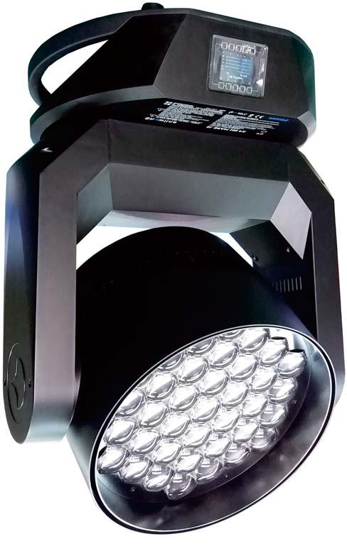
1 SL BEAM 5 FX LED LUMINAIRE
2 Showline Offices Showline - Dallas 1911 Petal Street Dallas, TX Tel: Fax: Showline - Europe Marssteden 152 Enschede 7547 TD The Netherlands Tel: Fax: Showline - Auckland -21 Kawana Street Northcote, Auckland 627 New Zealand Tel: Fax: Showline - Asia Unit C, 14/F, Roxy Industrial Centre No Kwai Cheong Road Kwai Chung, N.T., Hong Kong Tel: Fax: Website: The material in this manual is for information purposes only and is subject to change without notice. Showline assumes no responsiblitity for any errors or omissions which may appear in this manual. For comments and suggestions regarding corrections and/or updates to this manual, please visit the Showline website at or contact your nearest Showline office. Note: Information contained in this document may not be duplicated in full or in part by any person without prior written approval of Showline. Its sole purpose is to provide the user with conceptual information on the equipment mentioned. The use of this document for all other purposes is specifically prohibited. Document Number: SL BEAM 5 FX User s Manual Version as of: 12th April, 217 draft version SL BEAM 5 FX LED Luminaire installation & User s Manual 217 Philips Group. All rights reserved.
3 SL BEAM 5 FX LED Luminaires Installation & User s Manual Warnings and Notices When using electrical equipment, basic safety precautions should always be followed including the following: READ AND FOLLOW ALL SAFETY INSTRUCTIONS. Do not use outdoors. Do not mount near gas or electric heaters. Equipment should be mounted in locations and at heights where it will not readily be subject to tampering by unauthorized personnel. The use of accessory equipment not recommended by the manufacturer may cause an unsafe condition. Do not use this equipment for other than intended use. Refer service to qualified personnel. WARNING: You must have access to a mains circuit breaker or other power disconnect device before installing any wiring. BE sure that power is disconnected by removing fuses or turning the mains circuit breaker off before installation. Installing the device with power on may expose you to dangerous voltages and damage the device. A qualified electrician must perform this installation. WARNING: Refer to National Electrical Code and local codes for cable specifications. Failure to use proper cable can result in damage to equipment or danger to personnel. WARNING: This equipment is intended for installation in accordance with the Nation Electric Code and local regulations. It is also intended for installation in indoor applications only. Before any electrical work is performed, disconnect power at the circuit breaker or remove the fuse to avoid shock or damage to the control. It is recommended that a qualified electrician perform this installation. Additional Resources for DMX512 For more information on installing DMX512 control systems, the following publication is available for purchase from the United States Institute for Theatre Technology ( USITT), " Recommended Practice for DMX512: A Guide for Users and Installers, 2nd edition" ( ISBN: ). USITT Contact Information: USITT 315 South Crouse Avenue, Suite 2 Syracuse, NY Phone: or www. usitt. org Showline Limited Two-Year Warranty Showline offers a two-year limited warranty of its luminaires against defects in materials or workmanship from the date of delivery. A copy of Showline two-year limited warranty containing specific terms and conditions can be obtained by contacting your local Showline office.
4 Installation & User s Manual SL BEAM 5 FX LED Luminaires TABLE OF CONTENTS Showline Offices IMPORTANT INFORMATION Warnings and Notices Additional Resources for DMX512 Showline Limited Two-Year Warranty TABLE OF CONTENTS PREFACE About this Manual Included Items Accessories SL BEAM 5 FX LED LUMINAIRE OVERVIEW SL BEAM 5 FX LED Luminaire Components SL BEAM 5 FX LED Luminaire Menu System INSTALLATION AND SET UP Connecting Power Connecting SL BEAM 5 FX LED Luminaires to AC Power Connecting to the DMX512 Network Mounting Luminaire OPERATION AND PROGRAMMING LCD Display and Menu System LCD Display and Menu System Operation SL BEAM 5 FX LED Luminaire Menu Options Preset Recalling or Editing presets Color Filter Effect Edit user Chases Edit Rainbow Strobe/Timing Settings/Security Settings/General Settings/Factory Default Settings/DMX Settings/Artnet Settings Settings/Display Lock Fixture Password (PASSPIN) Status Quick Selection Button DMX Address Harmonize Color Calibration Dimming Curve Selection Master / Slave Operational Mode Inside Front Cover DMX CONTROL SL BEAM 5 FX LED Luminaire DMX Mapping Simple 8-Bit Mode Simple 8-Bit Group Modes RGBW 8-Bit Mode RGBW 8-Bit Group Modes RGBW 16-Bit Mode RGBW 16-Bit Group Modes Table of contents
5 SL BEAM 5 FX LED Luminaires Installation & User s Manual HSIC Mode HSIC Group Modes Mode Group Modes DMX Timing Detail RDM PARAMETER IDs SL BEAM 5 FX LED Luminaire RDM Parameter IDs CLEANING AND CARE Special Cleaning and Care Instructions Front Lens Cleaning Service and Maintenance TECHNICAL SPECIFICATIONS Operational Specifications Luminaire Dimensions Table of contents 3
6 Installation & User s Manual SL BEAM 5 FX LED Luminaires PREFACE 1. About this Manual The document provides installation and operation instructions for the following product: SL BEAM 5 FX LED Luminaire Please read all instructions before installing or using this product. Retain this manual for future reference. Additional product information and descriptions may be found on the product specification sheet. Note: The SL BEAM 5 FX LED Luminaire is universal voltage 1 to 24 VAC (auto-ranging). 2. Included Items Each SL BEAM 5 FX LED Luminaire includes the following items: SL BEAM 5 FX LED Luminaires PC1BE - AC Power Input Cable (39 inches / 1 meter), Powercon with Bare End* (*Note, user supplies and installs own AC input connector) Quick Start Guide SL BEAM 5 FX QuickStart Guide AC Input Cable(1m) ( USA, Canada & Latin America Markets Only) Omega Mounts AC Input Cable(1.5m) (International Markets Only) Figure 1: Included Items 3. Accessories SL BEAM 5 FX LED Luminaire Accessories Part Number MC SC HC Description Mega Claw, Black, Anodized Molded Yoke C-Clamp Light Weight Half Coupler 823 Safety Cable 4 About this Manual
7 SL BEAM 5 FX LED Luminaires Installation & User s Manual SL BEAM 5 FX LED LUMINAIRES OVERVIEW 1. SL BEAM 5 FX LED Luminaire Components Major Luminaire Components Snoot (Undetachable) Luminaire Head Luminaire Yoke Luminaire Base Handle (x2) Luminaire Base LCD Display / Menu System DMX512 / RDM Input DMX512 / RDM Output RJ45 Port For ArtNet Bottom of Fixture Base 14mm / 5.5 in 4 Camlock Positions AC Output AC Input 15mm / 4.1 in SL BEAM 5 FX LED Luminaire Overview 5
8 Installation & User s Manual SL BEAM 5 FX LED Luminaires 2. LCD Display / Menu System Home (menu settings) Edit a Preset Edit a Chase DMX512 Addressing Return to Main Screen LCD Display SL BEAM 5 FX DOWN Arrow Button LEFT Arrow Button RIGHT Arrow Button UP Arrow Button CHECK MARK (Accept) Button NOTE: Menu rotates with orientation of luminaire and menu buttons are always in the same position ( with rotation of menu) Figure 2: To rotate menu degrees from current orientation, press and hold the two center buttons for 2 seconds. LCD Display & Menu System Note: For Menu operation and programming details, refer to " LCD Display and Menu System" on page LCD Display / Menu System
9 SL BEAM 5 FX LED Luminaires Installation & User s Manual INSTALLATION AND SET UP 1. Power Requirements The SL BEAM 5 FX LED Luminaries operate on AC input voltages from 1 to 24 VAC. WARNING! SL BEAM 5 FX LED Luminaires do not contain an ON/OFF switch. Always disconnect power input cable to completely remove power from the luminaire when not in use. AC Power Operation When connected to an AC source, the luminaire operates on 1 to 24 volts AC (+/- 1%, auto-ranging). The luminaire contains an auto-ranging power supply. Each luminaire can draw up to 1 Watts. Note: For wiring of AC input connector, refer to "Connecting SL BEAM 5 FX LED Luminaires to AC Power" on page 7. Table 1: SL BEAM 5 FX LED Luminaire Voltage (VAC) vs. Current* Voltage ( AC) Total Current(A) Voltage ( AC) Total Current(A) WARNING! *These figures are based on the Maximum Allowable Input Current of 15 Amps (and the maximum power supply limit of 1 Watts for each connected unit). Do not overload circuits! IMPORTANT AC POWER CONNECTION NOTE: a. When using the daisy-chain connection method, ONLY connect SL BEAM 5 FX LED Luminaires to AC Output Connection of SL BEAM 5 FX LED Luminaires. DO NOT CONNECT OTHER TYPES OF LUMINAIRES OR DEVICES! b. Use only use approved cable types. c. Do not overload circuits! d. Do not connect SL BEAM 5 FX LED Luminaires to dimmed circuits. e. The MAXIMUM allowable number of SL BEAM 5 FX LED Luminaires which can be daisy-chained on one power feed are listed in Table 1, above. DO NOT EXCEED! Installation and Set Up 7
10 Installation & User s Manual SL BEAM 5 FX LED Luminaires 2. Connecting Power Luminaires can be powered in one of two ways: Direct connection to a AC power source using an AC input cable. For wiring of AC input connector, refer to " Connecting SL BEAM 5 FX LED Luminaires to AC Power" below. Connecting SL BEAM 5 FX LED Luminaires to AC Power If the luminaire is supplied with an AC input cable but you did not order an AC input connector, Table 2 describes how to connect power to your SL BEAM 5 FX LED Luminaire. Field wiring of the SL BEAM 5 FX LED Luminaire is straightforward. A total of 3 wires/conductors need to be brought to the luminaire. The following wiring scheme is required: Table 2: SL BEAM 5 FX LED Luminaire (IP2 Rated Models) AC Input Connections Wire Color Brown Blue Green/Yellow Purpose Main/Line(1 to 24VAC) Neutral Ground (Earth) CAUTION: In the event the AC input cable of this luminaire is damaged, it must be replaced, with an approved cable through an Authorized Showline Dealer or Service Center. AC Output AC Input AC Output Connector (on unit) AC Input Connector (on unit) Neutral Main / Line Main / Line Neutral AC Connector (on side of unit) AC Connector (on side of unit) Ground / Earth Ground / Earth Figure 3: SL BEAM 5 FX LED Luminaire AC Input & Output Connections 8 Connecting SL BEAM 5 FX to AC Power
11 SL BEAM 5 FX LED Luminaires Installation & User s Manual 3. Connecting to the DMX512 Network Basic DMX512 installation consists of connecting multiple SL BEAM 5 FX LED Luminaires together (up to 32 luminaires) in "daisy-chain" fashion. A cable runs from the control console (or DMX512 control source) to the DMX connector on the first SL BEAM 5 FX LED Luminaire. Another cable runs from the other DMX connector on the first unit to a DMX connector on the next SL BEAM 5 FX LED Luminaire (or DMX512 device to be controlled). DMX512 / RDM Output Connector DMX512 / RDM Input Connector Figure 4: SL BEAM 5 FX LED Luminaire DMX512 Input / Output Connections Note: For more information on DMX512 networking and systems, refer to "Additional Resources for DMX512" on page 1. For SL BEAM 5 FX LED Luminaire DMX Mapping, refer to "DMX CONTROL" on page 2. DMX512 (from console or control device) DMX512 (out from first to second luminaire) DMX512 (out to the next luminaire or DMX512 controlled device) SL BEAM 5 FX LED Luminaires DMX512 Conections DMX512 Signal Common (Drain) DMX512- DMX512+ XLR Pin Note: Remaining pins on each connector are not used. Figure 5: SL BEAM 5 FX LED Luminaire - DMX512 Connections Connecting to the DMX512 Network 9
12 Installation & User s Manual SL BEAM 5 FX LED Luminaires 4. Mounting Luminaire The SL BEAM 5 FX LED Luminaires are provided with the ability to hang via truss hooks, clamps, etc. (sold separately) or floor mounted (sitting on fixture base). Securely attach a hook, clamp, etc, to each Omega Mount (two supplied with luminaire). Attach the Omega Mounts to the luminaire base as illustrated in Figure 6 via the Camlocks. It is recommended (and may be required by local and national safety codes) to use and install a safety cable (sold separately). Whether hanging the fixture or free-standing on its base, be sure to leave enough space around the luminaire to allow proper, uninterrupted airflow for cooling and fixture head movement. Note: Mounting hooks, clamps, safety cables, etc. are sold separately or by others. For mounting accessories available for this product, refer to "Accessories" on page 3. SAFETY CABLE: Is sold separately and recommended for all hanging installation and may be required by national and local codes. Use enclosure handles for safety cable anchor points for this fixture. Omega Mount (x2) (supplied with luminaire) Luminaire Base Luminaire Yoke Luminaire Head Bottom of Fixture Base 14mm / 5.5 in 4 Camlock Positions 15mm / 4.1 in Omega Mounts Figure 6: Mounting the Fixture - Hanging Applications 1 Mounting Luminaire
13 SL BEAM 5 FX LED Luminaires Installation & User s Manual OPERATION AND PROGRAMMING 1. LCD Display and Menu System SL BEAM 5 FX LED Luminaires The SL BEAM 5 FX LED Luminaire s LCD Display and Menu System provides local control for accessing the following fixture s settings: Presets ( Standard and User Defined) Color Filter Effects ( Chases - preloaded and user defined) Strobe / Timing Settings Lock Fixture ( to prevent changes) Password Status Note: If there are multiple luminaires in a system, changes would need to be made at each LCD Menu as desired. Upon power up, the LCD will display the main screen showing the product type/ name. If DMX is enabled, the programmed address will appear after power up. 2. LCD Display and Menu System Operation The LCD Display Menu system consists of several categories. Use the Menu Buttons to access and make changes to the menu items. When the desired menu item is reached, press the desired Menu Button to display the menu options and to navigate and configure the menu options as required. To navigate and access menu settings/ selections: Step 1. Make sure unit is powered and turned on. Step 2. Press the desired button ( as shown in Figure 7) to access menu categories. Step 3. Use UP DOWN LEFT RIGHT arrow buttons to navigate through the various options and settings. Step 4. Make changes as desired. Press CHECK MARK ( OK) button to accept changes. Operation and Programming 11
14 Installation & User s Manual SL BEAM 5 FX LED Luminaires Home (menu settings) Edit a Preset Edit a Chase DMX512 Addressing Return to Main Screen LCD Display SL BEAM 5 FX DOWN Arrow Button LEFT Arrow Button RIGHT Arrow Button UP Arrow Button OK (Check Mark) Button NOTE: Menu rotates with orientation of Luminaire and menu buttons are always in the same position ( with rotation of menu) Figure 7: To rotate menu degrees manually from current orientation, press and hold the two center buttons for 2 seconds. LCD Display and Menu System 3. SL BEAM 5 FX LED Luminaire Main Menu Options Preset Presets are stored values of the luminaire s LED settings that can be recalled via the menu system or DMX. You can customize up to 31 presets via the menu system. Recalling or Editing Presets To recall or edit presets Edit a Preset Step 1. Select Preset from the main menu or from the preset shortcut key. Step 2. The top left field indicates the current preset or Off, when this field is selected (highlighted in blue), use the left and right buttons to scroll through all presets. Step 3. If you wish to edit the preset, use the Up and Down keys to scroll through the parameters. Once a parameter is selected, use the left and right arrow buttons to make adjustments. H S I C Edit a Preset 12% % 43% HSI Mode Notes:. If security features are enabled, the Up and Down arrows will have no effect. See Settings/Security on page 15.. Depending on the DMX map set assigned the DMX menu, different either RGBW or HSIC parameters will be available. Step 4. Once all values are adjusted as desired, press the Check Mark button to save the preset. Step 5. The Save Preset Menu option will appear. Use the left and right arrow buttons to select the preset number to save to. Note: This function allows you to save your current edits to a different preset number than you began editing. This is helpful to create copies of existing presets. 12 LCD Display and Menu System Operation
15 SL BEAM 5 FX LED Luminaires Installation & User s Manual Step 6. Press the Check Mark button to save the preset. You will be asked to confirm your saving operation. Step 7. The preset is now saved and can be recalled via the menu or DMX. Color Filter Color filters are 43 factory made colors that utilize the Harmonize Color Calibration system (refer to Harmonize Color Calibration on page for more information). They can be recalled via the menu system or DMX. To recall a color filter from the menu: Step 1. Select Color Filter from the main menu. Step 2. The top indicates the current color filter or Off, when this field is selected (highlighted in blue), use the left and right buttons to scroll through all color filters. Step 3. Use the Up and Down arrow keys to toggle to the Master Intensity field. use the Left and Right arrow keys to adjust the Master Intensity. Step 4. The menu will display a graphical indication of the color along with the color name. Note: The color filter will remain ON until you select a preset, chase, other color filter or send the unit DMX. Effects Effects are chases stored values of the luminaire s LED settings that can be recalled via the menu system or DMX. There are 1 factory defined chases and eight user adjustable chases. You can adjust the master intensity, speed, and fade values for any of the chases. Use the Up and Down buttons to select parameters and the Left and Right buttons to assign the different general fixture settings. When finished, press the Check button to exit the menu level. The adjustable parameters are described in Table 3. Table 3: Effects parameters Parameter User Chase / Built-in Chase Master Intensity Select Speed Fade Description Select from the different chases. Ajust the master intensity for ALL chases. Select a specific from all 13 patterns The total time each step of the chase will be recalled. The percentage of the time assigned by the speed that is crossfaded between steps. Editing User Chases Eight User chases can be further customized to create different effects on the fixture. To edit a User Chase, first use the up and down arrows to scroll to the Edit User Chase field and then press the Check Mark button. The Edit User Chase window will be displayed: Use the Up and Down buttons to select parameters and the Left and Right buttons to assign the different general fixture settings. When finished, press the Check button to exit the menu level. The adjustable parameters are described in Table 4. Edit a Chase Built In Chase 8 Total Steps 24 Speed 8 S Fade 7% Table 4: User Chase parameters Parameter User Chase Select which chase you wish to edit. Description Total Steps Displays the total steps used by the chase. This field is not editable. Edit Step Select a step to edit with the left right arrow buttons. Press the Check Mark button to edit the step. (see To edit and save a Step) New Step Add a step to the end of the chase. Press the Check Mark button to edit the new step (see To edit and save a Step) Delete Step Rainbow Delete the currently selected step in the Edit Step field. Press the Check mark button to delete the current step. Press the Check mark button to display the Rainbow Chase editor. Operation and Programming 13
16 Installation & User s Manual SL BEAM 5 FX LED Luminaires To edit and save a Step: Step 1. Select Edit Step or New Step from the Edit User Chase menu. Step 2. The top left field indicates the preset or color filter to be used for the step. When set to OFF no preset or color filter is to be used. Use LEFT and RIGHT buttons to scroll through all presets and color filters. Step 3. Use the Up and Down keys to scroll through the output parameters. Once a parameter is selected, use the left and right arrow buttons to make adjustments. Notes: If security features are enabled, the Up and Down arrows will have no effect. See Settings/Security on page 13. Fixtures with multiple pixel control include a parameter titled Pixel that allows you to independently adjust the output of each individual pixel or the entire fixture. Depending on the DMX map set assigned the DMX menu, different either RGBW or HSIC parameters will be available. Step 4. Once all values are adjusted as desired, press the Check Mark button to return to the Edit User Chase screen. Step 5. Continue editing steps as needed. When complete, press the Return to Main Menu button or up one level (as shown to the right). to exit the Edit User Chase window. Step 6. The user chase is now saved and can be recalled via the menu or DMX. Return to Main Menu Button Edit Rainbow: An additional option in the Edit User Chase options is to have the fixture generate a multi-colored chase using different pixels from the fixture. When you select Rainbow from the Edit Step window the Edit Rainbow window will display the following options. Table 5: Edit Rainbow parameters Parameter Direction Mode Number of Color Current Color Description Select either right or left to define the direction the rainbow effect runs. Select from Mode 1 / Mode 2. Select the number of colors used in the rainbow effect. (37 colors available in total) Will display the values of the current color selected. Press the Check Mark button to edit the selected color. Use the Up and Down buttons to select parameters and the Left and Right buttons to assign the settings. When finished, press the Check button to exit the menu level. The bottom of the Edit Rainbow window displays a graphical representation of the current rainbow effect. When finished editing the Rainbow, press the Main Menu button (as shown to the right). You will be asked to confirm that you wish to save the rainbow. Select Yes to save and return to the Edit a Chase window. Return to Main Menu Button Strobe/Timing The Strobe/Timing menu allows you to assign strobe and timing values from the menu system. These settings are instantly applied to any active Preset, Color filter, or Chase. Use the Up and Down buttons to select parameters and the Left and Right buttons to adjust the currently selected parameters. The adjustable parameters are described in Table 6 on page Operation and Programming
17 SL BEAM 5 FX LED Luminaires Installation & User s Manual Table 6: Strobe/Timing Parameters Parameter Description Master Intensity Overall fixture output intensity level. Strobe: X Strobe mode and rate value settings following DMX map (see DMX CONTROL for details). Duration The time each strobe flash remains ON. RotateMode The way how the fixture will rotate. Stop/CW/CCW The exact position for the INDEX from Rotate Mode (-255) Settings/Security All Showline fixtures have a multiple level locking feature. This allows you to configure the fixture and allow different menu access to multiple users. The menu system can be lock instantly or assigned to power on to a particular lock level. You can assign three different 4-digit PIN(personal identification number) codes to each unlock specific levels of functionality within the menu system. Anytime the fixture is locked, each PIN code will unlock all functions except the pertaining features assigned via the security level. Note: The Level 3 PIN will always unlock all functions. Table 7: Security Lock Levels Level 1 Level 2 Level 3 Lock Level Menu Functions Affected Edit Presets, Edit Chases, and Settings Menu Settings Menu All Use the Up and Down buttons to select security PIN codes. Press the Check button and then use Left and Right and Up Down buttons to assign the pin code. Press the Check button to save the new PIN code. The Power-Up Level parameters assigns a lock level to the fixture when power is applied. use the Up and Down buttons to select the Power-Up Level, and then use the Left and Right buttons to select the Power-up Level option. Table 8: PIN Level Parameters Enter Pass PIN Level 1 PIN Level 2 PIN Level 3 PIN Power-up Level Parameter Description Enter a PIN code matching the level codes assigned in the Settings/Security menu to toggle the current security level. Edit the PIN code used to toggle the Level 1 security. Edit the PIN code used to toggle the Level 2 security. Edit the PIN code used to toggle the Level 3 security. Select the security level to default to when the fixture is powered ON.. Disable PIN will disable all security functions.. Lock will lock all functions. Operation and Programming 15
18 Installation & User s Manual SL BEAM 5 FX LED Luminaires Settings/General Use the Up and Down buttons to select parameters and the Left and Right buttons to assign the different general fixture settings. When finished, press the Check button to exit the menu level. The adjustable parameters are described in Table 9. Table 9: General Level Parameters Power-Up Dim Response Parameter Description Select the action of the fixture when the unit is powered ON. You can select from Off, Last Set, Color filters, presets, and chases. Select Normal or Incandescent dimming response. Normal: Fixture LEDs dim with a normal response. Incandescent: Fixture LED s dim with an incandescent emulation response. The response to dimming commands will be slightly delayed at lower intensities. Dimming Curve Select one of four dimming curve choices (see Dimming Curve Selection for more information). Calibration Toggle Harmonize Color Calibration on or off ( see Harmonize Color Calibration for more information). Fan Control Select Auto or Off fan operation (see DMX CONTROL for more information). Settings/Factory Default Factory default menu settings can be recalled through this menu option. You can select if you wish to overwrite the user edited presets and chases. Use the Up and Down buttons to select parameters and the Left and Right buttons to assign the different settings. When finished, press the Check button to exit the menu level. The adjustable parameters are described in Table 1. Table 1: Facotry Default Parameters Protected Load Factory Service Parameter Description No - all menu items are able to be restored to factory defaults. Preset & Chase - user edited Presets and Chases are not able to be restored to factory defaults. No - no action. Yes - restored to factory default menu settings. To turn ON/OFF the feedback. Settings/DMX DMX configuration options are available in the DMX menu. Use the Up and Down buttons to select parameters and the Left and Right buttons to assign the fixture s DMX settings. When finished, press the Check button to exit the menu level. The adjustable parameters are described in Table 11. Table 11: DMX Setting Parameters DMX Enable Address Map When no DMX LED Group Pan/Tilt Setting Parameter Description Enable - Fixture will respond to DMX commands/signals. disable - Fixture will ignore DMX commands/signals. Assigns the fixture s DMX start address. Select the DMX map for the fixture to use (see DMX CONTROL section for more information). Selects the action of the fixture when the unit is powered ON and not receiving DMX Off - Turn off all LED output. Last Action - restore the last menu action. Power-up - follow the power-up value in the settings menu. Hold - continue with the last DMX values received. Select the number of LED groups to control via DMX (see DMX CONTROL section for more information). Set the parameters for Pan/Tilt 16 Operation and Programming
19 SL BEAM 5 FX LED Luminaires Installation & User s Manual Settings/ArtNet Settings Use the Up and Down buttons to select parameters and the Left and Right buttons to assign the different general fixture settings. When finished, press the Check button to exit the menu level. The adjustable parameters are described in Table 12. Table 12: ArtNET Parameters Parameter IP Address Set the IP address for the fixture. Net Select a Net number from -255 Sub-Net Select a Sub-Net number from -15 Universe Select a Universe number from -15. Description Protocol Priority DMX > ArtNET - DMX will run first priority. ArtNET > DMX ArtNET - ArtNET will run first priority. Settings / Display Options of the fixture s LCD display can be adjusted in the Display menu. Use the Up and Down buttons to select parameters and the Left and Right buttons to assign the fixture s DMX settings. When finished, press the Check button to exit the menu level. The adjustable parameters are described in Table 13. Table 13: LCD Display Parameters Parameter Flip Display Off Time Language Selected Yes - The display will be inverted. No - The display will not be inverted. Auto - The display will automatically invert depending upon fixture orientation. Assign a time for the display to automatically turn off after the last button press. A value of ON will leave the display on indefinitely. English is the only language supported. Description Lock Fixture You can lock all fixture functions, requiring a PIN code to access the menu functions. When you select this menu item, you are asked to confirm that you wish to lock the fixture. Once locked, all menu items can only be accessed by entering one of the three PIN codes assigned in the Settings/Security menu. (see Settings/Security on page 15 for more information). The PIN code used to unlock the fixture will only unlock the functionality assigned to that particular PIN code. Note: When the fixture is powered off, the Lock fixture function will be disabled. To assign fixture power-up security refer to (see Settings/Security on page 13 for more information). Operation and Programming 17
20 Installation & User s Manual SL BEAM 5 FX LED Luminaires Password (PassPIN) The Password menu item will display an Enter PassPIN dialog box. Use the Up Down Left Right buttons to enter a PIN code matching the codes assigned in the Settings/Security menu to toggle the current security level. Status The Status screen displays the current value of the master intensity and each LED of the luminaires. The number of pixels will vary depending upon fixture type. The Up Down Left Right arrows to scroll through the different LEDs and view their levels. The last Status item displayed shows the RDM UID and current Firmware Version Press the Check Mark button to exit the Status screen. Quick Selection Buttons The Showline menu system includes four quick selection buttons on the top of the menu. These keys provide direct access to common functions and act as shortcut to main menu items as described in Table 14 Table 14: General Level Parameters Quick select Button Description Main Menu Refer to Settings/General for more information. Edit a Preset Refer to Recalling or Editing Presets for more information. Effects / Edit a Chase Refer to Effects and Editing User Chases for more information. DMX Start Address Refer to DMX Address for more information. Return to Main Menu / Return Up a Menu Item DMX Address You can display and edit the current DMX start address for the fixture by pressing the Quick Select button on the top of the menu system (as shown right). The current DMX start address will be display in large digits. DMX Address To edit the DMX start address: Step 1. Press the Check Mark button to begin the DMX start address editing. The last digit will change to a blue color. Step 2. use the UP and Down arrows to change the value of the currently selected digit. Step 3. Use the Left and Right arrows to select another digit to adjust. Step 4. Press the Check Mark button to save the new DMX Start Address. Address 255 Operation and Programming

21 SL BEAM 5 FX LED Luminaires Installation & User s Manual 4. Harmonize Color Calibration Harmonize is a proprietary, advanced LED color matching system, consisting of 3 correction modules: RGB, RGBW and Cool White/Warm White. Every Showline fixture undergoes rigorous testing to provide you with consistent control of color and intensity as well as output of the highest quality. When enabled either via DMX or the fixture s menu, the Harmonize technoloy will ensure that colors match from fixture-to-fixture and pixel-to- pixel. As the Harmonize system matches Showline products, they will all operate in the same color space. Use the Harmonize system when perfect color matching is an essential requirement. R G B x y Through the menu, you are able to select one of four dimming curves: Linear Curve PL_Curve S_Curve Square Curve Linear Curve PL_Curve* Lumen Output DMX Value S_Curve Square Curve Lumen Output Lumen Output Lumen Output DMX Value *PL Curve follows the dimming curve of Philips Selecon PL series LED luminaires. DMX Value DMX Value Figure 8: SL BEAM 5 FX LED Luminaire Dimmer Curves DIMMING CURVE SELECTION
22 Installation & User s Manual SL BEAM 5 FX LED Luminaires 6. Master / Slave Operational Mode The Master / Slave Operational Mode allows one SL BEAM 5 FX LED Luminaire to act as the "Master" unit and all other connected units are controlled by this unit. When a unit is set to "Slave" mode, it will only listen to and follow any commands sent from a "Master" unit. Only one "Master" unit is allowed in this type of operation. Note: For more information on DMX512 networking and systems, refer to "Additional Resources for DMX512" on page 1. For SL BEAM 5 FX LED Luminaire DMX Mapping, refer to "DMX CONTROL" on page. DMX512 (from console or control device) DMX512 (out from first to second luminaire) DMX512 (out to the next luminaire or DMX512 controlled device) Master Unit Slave Unit SL BEAM 5 FX LED Luminaires Slave Unit Figure 9: SL BEAM 5 FX LED Luminaire - Master / Slave Configuration 2 Master / Slave Operational Mode
23 SL BEAM 5 FX LED Luminaires Installation & User s Manual DMX CONTROL This section contains information for operating the luminaire using DMX control in Simple 8-bit, RGBW 8-bit, RGBW 16-bit, HSIC (Hue, Saturation, Intensity and Color Correction) or modes. For Menu options and detailed information, see "LCD Display and Menu System on page 6. Note: These tables assume a DMX start address of 1. When a different starting address is used, this address becomes channel 1 function and other functions follow in sequence. 1. SL BEAM 5 FX LED Luminaire DMX Mapping Simple 8-Bit Mode Table 15 provides DMX channel mapping of all DMX512 control values when the SL BEAM 5 FX LED Luminaire is in simple 8-bit DMX512 mode (as set by the luminaire s menu system). Table 15: SL BEAM 5 FX LED Luminaire DMX Mapping (Simple 8 - Bit Mode) DMX Parameter Range DMX Range% Default Description 1 Pan bit control of Pan 2 Tilt bit control of Tilt 3 Master Intensity bit control of Intensity of LED settings 4 Strobe -255 Controls strobe operations as follows: Open Closed Slow Rand Med Rand Fast Rand Strobe Range Pulse + Slow Rand Pulse + Med Rand Pulse + Fast Rand Pulse + Range Pulse - Slow Rand Pulse - Med Rand Pulse - Fast Rand Pulse - Range DMX -2 DMX 3-5 DMX 6-7 DMX 8-1 DMX DMX (fastest) DMX DMX DMX DMX DMX 2-3 DMX 4-5 DMX 6-7 DMX Zoom -255 Variable control of zoom from Rotate Mode -255 ( Disabled - when Zoom DMX < 2) -5% =DMX -14 OFF (Action same as Home) 6%-36% =DMX Spin Mode 37%-67% =DMX Index Mode 68%-1% =DMX Reserved for future use 7 Position/Speed ( Disabled - when Zoom DMX < 2) Spin Mode: 49%-51% Home 52% - 1%: Spin Speed Clockwise 48% - : Spin Speed Counter Clockwise Index Mode: 49% - 51% Home Degree 52%-1% Index Clockwise Home degree to + degrees 48% - Spin Index Counter Clockwise Home -degrees 8 Control -255 Set control channel value to desired action, hold value for at least 5 seconds, then turn to. Set control channel value to without any scaling. Default Setting on Console DIM Response_Normal DIM Response_Incandescent Dimming Curve_linear Dimming Curve_Square Dimming Curve_S-Curve Diming Curve_PL-Curve Calibration_OFF Calibration_ON Fan_Auto Fan_Off Reserved(Future Use) =DMX -4 =DMX 5-9 =DMX 1-14 =DMX 3-34 =DMX =DMX 4-44 =DMX =DMX 7-74 =DMX =DMX 8-84 =DMX =DMX Red bit control of Red LEDs from to full. 1 Green bit control of Green LEDs from to full. 11 Blue bit control of Blue LEDs from to full. 12 White bit control of White LEDs from to full. DMX CONTROL 21
24 Installation & User s Manual SL BEAM 5 FX LED Luminaires Simple 8-Bit Group Modes Table 16 provides DMX channel mapping of all DMX512 control values when the Luminaire is operated in various Simple 8- bit DMX512 Group Control Modes. SL BEAM 5 FX LED Table 16: SL BEAM 5 FX LED Luminaire DMX Mapping ( Simple 8- Bit Group Modes) Simple 8 bit mode DMX CHANNEL Group Mode 1 Group Mode 1 Pan Pan Tilt Master Intensity Strobe Zoom Rotate Mode Position/Speed Control Red_1 Green_1 Blue_1 White_1 Red_2 Tilt Master Intensity Strobe Zoom Rotate Mode Position/Speed Control Red_1-37 Green_37 Blue1_37 White1_37 14 Green_2 15 Blue_2 16 White_2 17 Red_3 Green_3 Blue_3 2 White_3 21 Red_4 22 Green_4 23 Blue_4 24 White_4 25 Red_5 26 Green_5 27 Blue_5 28 White_5 29 Red_6 3 Green_6 31 Blue_6 32 White_6 33 Red_7 34 Green_7 35 Blue_7 36 White_7 37 Red_8 38 Green_8 39 Blue_8 4 White_8 41 Red_9 42 Green_9 43 Blue_9 44 White_9 45 Red_1 46 Green_1 47 Blue_1 48 White_1 49 Red_11 5 Green_11 51 Blue_11 52 White_11 53 Red_12 54 Green_12 55 Blue_12 56 White_12 57 Red_13 58 Green_13 59 Blue_13 6 White_13 61 Red_14 62 Green_14 63 Blue_14 64 White_14 65 Red_15 66 Green_15 67 Blue_15 68 White_15 69 Red_16 7 Green_16 71 Blue_16 72 White_16 73 Red_17 74 Green_17 75 Blue_17 76 White_17 77 Red_ 78 Green_ 79 Blue_ 8 White_ 81 Red_ 82 Green_ 83 Blue_ 84 White_ Red_2 Green_2 Blue_2 White_2 Red_21 Green_21 Blue_21 White_21 Red_22 Green_22 Blue_22 White_22 Red_23 Green_23 Blue_23 White_23 Red_24 Green_24 Blue_24 White_24 Red_25 Green_25 Blue_25 White_25 Red_26 Green_26 Blue_26 White_26 Red_27 Green_27 Blue_27 White_27 Red_28 Green_28 Blue_28 White_28 Red_29 Green_29 Blue_29 White_29 Red_3 Green_3 Blue_3 White_3 Red_31 Green_31 Blue_31 White_31 Red_32 Green_32 Blue_32 White_32 Red_33 Green_33 Blue_33 White_33 Red_34 Green_34 Blue_34 White_34 Red_35 Green_35 Blue_35 White_35 Red_36 Green_36 Blue_36 White_36 Red_37 Green_37 Blue_37 White_37 22 Simple 8-Bit Group Modes
25 SL BEAM 5 FX LED Luminaires Installation & User s Manual RGBW 8 - Bit Mode Table 17 provides DMX channel mapping of all DMX512 control values when the SL BEAM 5 FX LED Luminaire is in RGBW 8-Bit DMX512 mode (as set by the luminaire s menu system). Table 17: SL BEAM 5 FX LED Luminaire DMX Mapping (RGBW 8-Bit Mode) DMX 1 Parameter Range DMX Range% Default Description Pan Tilt Master Intensity - High Color Presets -255 RGBW 8 - Bit Mode 23
26 Installation & User s Manual SL BEAM 5 FX LED Luminaires Table 17: SL BEAM 5 FX LED Luminaire DMX Mapping (RGBW 8-Bit Mode) DMX Parameter Range DMX Range% Default Description 4 CF_22_Double C.T Blue DMX CF_25_Full C.T Blue DMX RGBW 8 - Bit Mode
27 SL BEAM 5 FX LED Luminaires Installation & User s Manual Table 17: SL BEAM 5 FX LED Luminaire DMX Mapping (RGBW 8-Bit Mode) DMX Parameter Range DMX Range% Default Description 4 5 Strobe 6 Duration RGBW 8 - Bit Mode 25
28 Installation & User s Manual SL BEAM 5 FX LED Luminaires Table 17: SL BEAM 5 FX LED Luminaire DMX Mapping (RGBW 8-Bit Mode) DMX Parameter Range DMX Range% Default Description 7 Zoom Rotate Mode -255 ( Disabled - when Zoom DMX < 2) -5% =DMX -14 OFF (Action same as Home) 6%-36% =DMX Spin Mode 37%-67% =DMX Index Mode 68%-1% =DMX Reserved for future use 9 1 Position/Speed Focus Timing ( Disabled - when Zoom DMX < 2) Spin Mode: 49%-51% Home 52% - 1%: Spin Speed Clockwise 48% - : Spin Speed Counter Clockwise Index Mode: 49% - 51% Home Degree 52%-1% Index Clockwise Home degree to + degrees 48% - Spin Index Counter Clockwise Home -degrees 11 Timing Set control channel value to desired action, hold value for at least 5 seconds, then turn to. Set control channel value to without any scaling. 12 Control -255 Default Setting on Console DIM Response_Normal DIM Response_Incandescent Dimming Curve_linear Dimming Curve_Square Dimming Curve_S-Curve Diming Curve_PL-Curve Calibration_OFF Calibration_ON Fan_Auto Fan_Off Reserved(Future Use) =DMX -4 =DMX 5-9 =DMX 1-14 =DMX 3-34 =DMX =DMX 4-44 =DMX =DMX 7-74 =DMX =DMX 8-84 =DMX =DMX Red bit control of Red LEDs from to full 14 Green bit control of Green LEDs from to full 15 Blue bit control of Blue LEDs from to full 16 White bit control of White LEDs from to full 26 RGBW 8 - Bit Mode
29 SL BEAM 5 FX LED Luminaires Installation & User s Manual RGBW 8-Bit Group Modes Table provides DMX channel mapping of all DMX512 control values when the SL BEAM 5 FX LED Luminaire is operated in various RGBW 8- bit DMX512 Group Control Modes. Table : SL BEAM 5 FX LED Luminaire DMX Mapping ( RGBW 8- Bit Group Modes) RGBW 8 bit mode DMX CHANNEL Group Mode 1 Group Mode 1 Pan Pan Tilt Master Intensity Color Presets Strobe Duration Zoom Rotate Mode Tilt Master Intensity Color Presets Strobe Duration Zoom Rotate Mode 9 Position/Speed Position/Speed 1 Focus Timing Focus Timing 11 Timing Timing Control Red_1 Green_1 Blue_1 White_1 Red_2 Green_2 Blue_2 White_2 Red_3 Green_3 Blue_3 White_3 Red_4 Green_4 Blue_4 White_4 Red_5 Green_5 Blue_5 White_5 Red_6 Green_6 Blue_6 White_6 Red_7 Green_7 Blue_7 White_7 Red_8 Green_8 Blue_8 White_8 Red_9 Green_9 Blue_9 White_9 Red_1 Green_1 Blue_1 White_1 Red_11 Green_11 Blue_11 White_11 Red_12 Green_12 Blue_12 White_12 Red_13 Green_13 Blue_13 White_13 Red_14 Green_14 Blue_14 White_14 Red_15 Green_15 Blue_15 White_15 Red_16 Green_16 Blue_16 White_16 Red_17 Green_17 Blue_17 White_17 Red_ Green_ Blue_ White_ Red_ Green_ Blue_ White_ Control Red_1- Green_ Blue_ White_ Red_2 Green_2 Blue_2 White_2 Red_21 Green_21 Blue_21 White_21 Red_22 Green_22 Blue_22 White_22 Red_23 Green_23 Blue_23 White_23 Red_24 Green_24 Blue_24 White_24 Red_25 Green_25 Blue_25 White_25 Red_26 Green_26 Blue_26 White_26 Red_27 Green_27 Blue_27 White_27 Red_28 Green_28 Blue_28 White_28 Red_29 Green_29 Blue_29 White_29 Red_3 Green_3 Blue_3 White_3 Red_31 Green_31 Blue_31 White_31 Red_32 Green_32 Blue_32 White_32 Red_33 Green_33 Blue_33 White_33 Red_34 Green_34 Blue_34 White_34 Red_35 Green_35 Blue_35 White_35 Red_36 Green_36 Blue_36 White_36 Red_37 Green_37 Blue_37 White_37 RGBW 8-Bit Group Modes 27
30 Installation & User s Manual SL BEAM 5 FX LED Luminaires RGBW 16 - Bit Mode Table provides DMX channel mapping of all DMX512 control values when the SL BEAM 5 FX LED Luminaire is in RGBW 16-bit DMX512 mode (as set by the luminaire s menu system). Table : SL BEAM 5 FX LED Luminaire DMX Mapping (RGBW 16-Bit Mode) DMX Parameter Range DMX Range% Default Description 28 RGBW 16 - Bit Mode
31 SL BEAM 5 FX LED Luminaires Installation & User s Manual Table : SL BEAM 5 FX LED Luminaire DMX Mapping (RGBW 16-Bit Mode) DMX Parameter Range DMX Range% Default Description 7 Color Presets CF_22_Double C.T Blue DMX CF_25_Full C.T Blue DMX 1-12 RGBW 16-Bit Mode 29
32 Installation & User s Manual SL BEAM 5 FX LED Luminaires Table : SL BEAM 5 FX LED Luminaire DMX Mapping (RGBW 16-Bit Mode) DMX Parameter Range DMX Range% Default Description 7 Color Presets 8 Strobe 9 Duration 3 RGBW 16 - Bit Mode
33 SL BEAM 5 FX LED Luminaires Installation & User s Manual Table : SL BEAM 5 FX LED Luminaire DMX Mapping (RGBW 16-Bit Mode) DMX Parameter Range DMX Range% Default Description 1 Zoom % (Disabled - When Zoom channel DMX < 2) -5% =DMX -14 OFF(Action same as Home) 6%-36% =DMX Spin Mode 11 Rotate Mode % 37%-67% =DMX Index Mode 68%-1% =DMX Reserved for future use 12 Position/Speed % 127 (Disabled - When Zoom channel DMX < 2) Spin Mode: 49%-51% Home 52% - 1%: Spin Speed Clockwise 48% - : Spin Speed Counter Clockwise Index Mode: 49% - 51% Home Degree 52%-1% Index Clockwise Home degree to + degrees 48% - Spin Index Counter Clockwise Home -degrees 13 Focus Timing % Intensity Timing % 255 Allows for timing control of intensity. should default to 255 for smoothest actions using console and/or manual fades. - See Timing chart for more details. 15 Timing % 255 Allows for timing control of color. should default to 255 for smoothest actions using console and/or manual fades. - See Timing chart for more details % 255 Allows for timing control of zoom Set control channel value to desired action, hold value for at least 5 seconds, then turn to. Set control channel value to without any scaling. 17 Control % Default Setting on Console DIM Response_Normal DIM Response_Incandescent Dimming Curve_linear Dimming Curve_Square Dimming Curve_S-Curve Diming Curve_PL-Curve Calibration_OFF Calibration_ON Fan_Auto Fan_Off Reserved(Future Use) =DMX -4 =DMX 5-9 =DMX 1-14 =DMX 3-34 =DMX =DMX 4-44 =DMX =DMX 7-74 =DMX =DMX 8-84 =DMX =DMX 9-25 Red High Byte Red Low Byte % 16 bit control of Red LEDs from to full 2 21 Green High Byte Green Low Byte % 16 bit control of Green LEDs from to full Blue High Byte Blue Low Byte % 16 bit control of Blue LEDs from to full White High Byte White Low Byte % 16 bit control of White LEDs from to full RGBW 16 - Bit Mode 31
34 Installation & User s Manual SL BEAM 5 FX LED Luminaires RGBW 16-Bit Group Modes Table 2 provides DMX channel mapping of all DMX512 control values when the Luminaire is operated in various RGBW 16- bit DMX512 Group Control Modes. SL BEAM 5 FX LED Table 2: SL BEAM 5 FX LED Luminaire DMX Mapping ( RGBW 16- Bit Group Modes) RGBW 16 bit mode DMX CHANNEL Group Mode 1 Group Mode Pan - High Byte Pan - High Byte Pan - Low Byte Pan - Low Byte Tilt - High Byte Tilt - High Byte Tilt - Low Byte Tilt - Low Byte Master Intensity - High Master Intensity - High Master Intensity - Low Master Intensity - Low Color Presets Color Presets Strobe Strobe Duration Duration Zoom Zoom Rotate Mode Rotate Mode Position/Speed Position/Speed Focus Timing Focus Timing Intensity Timing Intensity Timing Color Timing Color Timing Zoom Timing Zoom Timing Control Control Red_1 - High Byte Red_1- - High Byte Red_1 - Low Byte Red_1- - Low Byte Green_1 - High Byte Green_1- - High Byte Green_1 - Low Byte Green_1- - Low Byte Blue_1 - High Byte Blue_1- - High Byte Blue_1 - Low Byte Blue_1- - Low Byte White_1 - High Byte White_1- - High Byte White_1 - Low Byte White_1- - Low Byte Red_2 - High Byte Red_2 - Low Byte Green_2 - High Byte Green_2 - Low Byte Blue_2 - High Byte Blue_2 - Low Byte White_2 - High Byte White_2 - Low Byte Red_3 - High Byte Red_3 - Low Byte Green_3 - High Byte Green_3 - Low Byte Blue_3 - High Byte Blue_3 - Low Byte White_3 - High Byte White_3 - Low Byte Red_4 - High Byte Red_4 - Low Byte Green_4 - High Byte Green_4 - Low Byte Blue_4 - High Byte Blue_4 - Low Byte White_4 - High Byte White_4 - Low Byte Red_5 - High Byte Red_5 - Low Byte Green_5 - High Byte Green_5 - Low Byte Blue_5 - High Byte Blue_5 - Low Byte White_5 - High Byte White_5 - Low Byte Red_6 - High Byte Red_6 - Low Byte Green_6 - High Byte Green_6 - Low Byte Blue_6 - High Byte Blue_6 - Low Byte White_6 - High Byte White_6 - Low Byte Red_7 - High Byte Red_7 - Low Byte Green_7 - High Byte Green_7 - Low Byte Blue_7 - High Byte Blue_7 - Low Byte White_7 - High Byte White_7 - Low Byte Red_8 - High Byte Red_8 - Low Byte Green_8 - High Byte Green_8 - Low Byte Blue_8 - High Byte Blue_8 - Low Byte White_8 - High Byte White_8 - Low Byte 82 Red_9 - High Byte 17 Red_2 - High Byte 258 Red_31 - High Byte 83 Red_9 - Low Byte 171 Red_2- Low Byte 259 Red_31- Low Byte 84 Green_9 - High Byte 172 Green_2 - High Byte 26 Green_31 - High Byte 85 Green_9 - Low Byte 173 Green_2 - Low Byte 261 Green_31 - Low Byte 86 Blue_9 - High Byte 174 Blue_2 - High Byte 262 Blue_31 - High Byte 87 Blue_9 - Low Byte 175 Blue_2 - Low Byte 263 Blue_31 - Low Byte 88 White_9 - High Byte 176 White_2- High Byte 264 White_31- High Byte 89 White_9 - Low Byte 177 White_2 - Low Byte 265 White_31 - Low Byte 9 Red_1 - High Byte 178 Red_21 - High Byte 266 Red_32 - High Byte 91 Red_1 - Low Byte 179 Red_21 - Low Byte 267 Red_32 - Low Byte 92 Green_1 - High Byte Green_21 - High Byte 268 Green_32 - High Byte 93 Green_1 - Low Byte 1 Green_21 - Low Byte 269 Green_32 - Low Byte 94 Blue_1 - High Byte 2 Blue_21 - High Byte 27 Blue_32 - High Byte 95 Blue_1 - Low Byte 3 Blue_21 - Low Byte 271 Blue_32 - Low Byte 96 White_1 - High Byte 4 White_21 - High Byte 272 White_32 - High Byte 97 White_1 - Low Byte 5 White_21 - Low Byte 273 White_32 - Low Byte 98 Red_11 - High Byte 6 Red_22 - High Byte 274 Red_33 - High Byte 99 Red_11 - Low Byte 7 Red_22 - Low Byte 275 Red_33 - Low Byte 1 Green_11 - High Byte 8 Green_22 - High Byte 276 Green_33 - High Byte 11 Green_11 - Low Byte 9 Green_22 - Low Byte 277 Green_33 - Low Byte 12 Blue_11 - High Byte Blue_22 - High Byte 278 Blue_33 - High Byte 13 Blue_11 - Low Byte 1 Blue_22 - Low Byte 279 Blue_33 - Low Byte 14 White_11 - High Byte 2 White_22 - High Byte 28 White_33 - High Byte 15 White_11 - Low Byte 3 White_22 - Low Byte 281 White_33 - Low Byte 16 Red_12 - High Byte 4 Red_23 - High Byte 282 Red_34 - High Byte 17 Red_12 - Low Byte 5 Red_23 - Low Byte 283 Red_34 - Low Byte 18 Green_12 - High Byte 6 Green_23 - High Byte 284 Green_34 - High Byte 19 Green_12 - Low Byte 7 Green_23 - Low Byte 285 Green_34 - Low Byte 11 Blue_12 - High Byte 8 Blue_23 - High Byte 286 Blue_34 - High Byte 111 Blue_12 - Low Byte 9 Blue_23 - Low Byte 287 Blue_34 - Low Byte 112 White_12 - High Byte 2 White_23 - High Byte 288 White_34 - High Byte 113 White_12 - Low Byte 21 White_23 - Low Byte 289 White_34 - Low Byte 114 Red_13 - High Byte 22 Red_24 - High Byte 29 Red_35 - High Byte 115 Red_13 - Low Byte 23 Red_24 - Low Byte 291 Red_35 - Low Byte 116 Green_13 - High Byte 24 Green_24 - High Byte 292 Green_35 - High Byte 117 Green_13 - Low Byte 25 Green_24 - Low Byte 293 Green_35 - Low Byte 1 Blue_13 - High Byte 26 Blue_24 - High Byte 294 Blue_35 - High Byte 1 Blue_13 - Low Byte 27 Blue_24 - Low Byte 295 Blue_35 - Low Byte 12 White_13 - High Byte 28 White_24 - High Byte 296 White_35 - High Byte 121 White_13 - Low Byte 29 White_24 - Low Byte 297 White_35 - Low Byte 122 Red_14 - High Byte 21 Red_25 - High Byte 298 Red_36 - High Byte 123 Red_14 - Low Byte 211 Red_25 - Low Byte 299 Red_36 - Low Byte 124 Green_14 - High Byte 212 Green_25 - High Byte 3 Green_36 - High Byte 125 Green_14 - Low Byte 213 Green_25 - Low Byte 31 Green_36 - Low Byte 126 Blue_14 - High Byte 214 Blue_25 - High Byte 32 Blue_36 - High Byte 127 Blue_14 - Low Byte 215 Blue_25 - Low Byte 33 Blue_36 - Low Byte 128 White_14 - High Byte 216 White_25 - High Byte 34 White_36 - High Byte 129 White_14 - Low Byte 217 White_25 - Low Byte 35 White_36 - Low Byte 13 Red_15 - High Byte 2 Red_26 - High Byte 36 Red_37 - High Byte 131 Red_15 - Low Byte 2 Red_26 - Low Byte 37 Red_37 - Low Byte 132 Green_15 - High Byte 22 Green_26 - High Byte 38 Green_37 - High Byte 133 Green_15 - Low Byte 221 Green_26 - Low Byte 39 Green_37 - Low Byte 134 Blue_15 - High Byte 222 Blue_26 - High Byte 31 Blue_37 - High Byte 135 Blue_15 - Low Byte 223 Blue_26 - Low Byte 311 Blue_37 - Low Byte 136 White_15 - High Byte 224 White_26 - High Byte 312 White_37 - High Byte 137 White_15 - Low Byte 225 White_26 - Low Byte 313 White_37 - Low Byte 138 Red_16 - High Byte 226 Red_27 - High Byte 139 Red_16 - Low Byte 227 Red_27 - Low Byte 14 Green_16 - High Byte 228 Green_27 - High Byte 141 Green_16 - Low Byte 229 Green_27 - Low Byte 142 Blue_16 - High Byte 23 Blue_27 - High Byte 143 Blue_16 - Low Byte 231 Blue_27 - Low Byte 144 White_16 - High Byte 232 White_27 - High Byte 145 White_16 - Low Byte 233 White_27 - Low Byte 146 Red_17 - High Byte 234 Red_28 - High Byte 147 Red_17 - Low Byte 235 Red_28 - Low Byte 148 Green_17 - High Byte 236 Green_28 - High Byte 149 Green_17 - Low Byte 237 Green_28 - Low Byte 15 Blue_17 - High Byte 238 Blue_28 - High Byte 151 Blue_17 - Low Byte 239 Blue_28 - Low Byte 152 White_17 - High Byte 24 White_28 - High Byte 153 White_17 - Low Byte 241 White_28 - Low Byte 154 Red_ - High Byte 242 Red_29 - High Byte 155 Red_ - Low Byte 243 Red_29 - Low Byte 156 Green_ - High Byte 244 Green_29 - High Byte 157 Green_ - Low Byte 245 Green_29 - Low Byte 158 Blue_ - High Byte 246 Blue_29 - High Byte 159 Blue_ - Low Byte 247 Blue_29 - Low Byte 16 White_ - High Byte 248 White_29 - High Byte 161 White_ - Low Byte 249 White_29 - Low Byte 162 Red_ - High Byte 25 Red_3 - High Byte 163 Red_ - Low Byte 251 Red_3 - Low Byte 164 Green_ - High Byte 252 Green_3 - High Byte 165 Green_ - Low Byte 253 Green_3 - Low Byte 166 Blue_ - High Byte 254 Blue_3 - High Byte 167 Blue_ - Low Byte 255 Blue_3 - Low Byte 168 White_ - High Byte 256 White_3 - High Byte 169 White_ - Low Byte 257 White_3 - Low Byte 32 RGBW 16-Bit Group Modes
SL BEAM 300 FX LED Luminaire
 SL BEAM 3 FX LED Luminaire Showline Offices Showline - Dallas 11 Petal Street Dallas, TX 75238 Tel: 214-647-788 Fax: 214-647-83 Showline - Europe Marssteden 152 Enschede 7547 TD The Netherlands Tel: +31
Document Number: SL BAR 720ZT QuickStart Guide Version as of: Draft version
 SL BAR 72ZT SL BAR 72ZT QuickStart Guide Showline Offices Dallas 1911 Petal Street Dallas, TX 75238 Tel : + 1 214-647-788 Fax: + 1 214-647-83 Asia Unit C, 14/ F, Roxy Industrial Centre No. 41-49 Kwai Cheong
Showline Offices Dallas Petal Street Dallas, TX Tel: Fax:
 Showline Offices Dallas 10911 Petal Street Dallas, TX 75238 Tel: +1 214-647-7880 Fax: +1 214-647-8030 Asia Unit C, 14/F, Roxy Industrial Centre No. 41-49 Kwai Cheong Road Kwai Chung, N.T., Hong Kong Tel:
Document Number: SL estrip 10 RGBW LED Luminaires User Manual
 SL estrip RGBW www.philips.com/showline Document Number: SL estrip RGBW LED Luminaires User Manual Version as of : 26th May 24 SL estrip RGBW User s Manual 24 SL estrip RGBW IMPORTANT INFORMATION Warnings
Showline Offices Dallas Petal Street Dallas, TX Tel: Fax:
 Showline Offices Dallas 10911 Petal Street Dallas, TX 75238 Tel: +1 214-647-7880 Fax: +1 214-647-8030 Asia Unit C, 14/F, Roxy Industrial Centre No. 41-49 Kwai Cheong Road Kwai Chung, N.T., Hong Kong Tel:
Showline Offices Dallas Petal Street Dallas, TX Tel: Fax:
 Showline Offices Dallas 10911 Petal Street Dallas, TX 75238 Tel: +1 214-647-7880 Fax: +1 214-647-8030 Asia Unit C, 14/F, Roxy Industrial Centre No. 41-49 Kwai Cheong Road Kwai Chung, N.T., Hong Kong Tel:
SL WASH 350 RGBW LED Luminaire
 SL WASH 350 RGBW LED Luminaire Showline Offices Dallas 10911 Petal Street Dallas, TX 75238 Tel: +1 214-647-7880 Fax: +1 214-647-8030 Asia Unit C, 14/F, Roxy Industrial Centre No. 41-49 Kwai Cheong Road
Website: Version as of: 17th Sep, 2015 Rev1.0. SL ParBlazer 100 UV Installation & User s Manual
 SL ParBlazer 100 UV Showline Offices Showline - Dallas 10911 Petal Street Dallas, TX 75238 U.S.A Tel: 214-647-7880 Fax: 214-647-8030 Showline - Europe Marssteden 152 Enschede 7547 TD The Netherlands Tel:
ETC Installation Guide
 ColorSource PAR v1.7 Overview The ColorSource PAR is an affordable LED fixture that uses the RGB-L (red, green, blue, and lime) color system to provide a rich, bright light. The ColorSource PAR is available
SL BEAM 100 LED LUMINAIRE
 SL BEAM 1 LED LUMINAIRE Note: Information contained in this document may not be duplicated in full or in part by any person without prior written approval of Showline. Its sole purpose is to provide the
VBAR 270. User Manual. Version 1.2
 VBAR 270 User Manual Version 1.2 VBAR 270 User Manual Page 1of 19 Introduction Thank you for purchasing VBAR 270. VBAR 270 is a LED light fixture for professional use. Using the RGB color mixing technology
ETC Installation Manual
 ColorSource Spot Overview The is an affordable profile fixture that offers the quality and support of an ETC LED fixture. Utilizing an RGB-L color mixing system, the produces amazing color and output for
Ostar Eye K18. Beam and Kaleido Effects. User manual. 6. Fixture Cleaning. Please read the instructions carefully before use
 6. Fixture Cleaning The cleaning of internal and external optical lenses and/or mirrors must be carried out periodically to optimize light output. Cleaning frequency depends on the Ostar Eye K18 Beam and
Update to VLX Wash software (03/22/13):
:") Page 1 of 6 SUBJECT: VLX Wash Luminaire Software Release DISTRIBUTION: Service Centers, End Users SERIES: VLX Wash STATUS: Routine Introduction IMPORTANT! This bulletin supersedes Vari-Lite Technical Bulletin
Page 1 of 6 SUBJECT: VLX Wash Luminaire Software Release DISTRIBUTION: Service Centers, End Users SERIES: VLX Wash STATUS: Routine Introduction IMPORTANT! This bulletin supersedes Vari-Lite Technical Bulletin
Release Notes & Updated Channel Map
 Page 1 of 6 SUBJECT: VLX Wash Luminaire Software Release DISTRIBUTION: Service Centers, End Users SERIES: VLX STATUS: Routine Introduction Embedded Software Release Vari-Lite has a new software release
SPOT MOVING HEAD M1S150W USER MANUAL. For safety, please read this user manual carefully before initial use.
 SPOT MOVING HEAD M1S150W USER MANUAL For safety, please read this user manual carefully before initial use. Event Lighting reserves the right to revise the manual at any time. Information and specifications
Quick Reference Guide
 Ilumipod 42 IP Series Quick Reference Guide About this Guide Disclaimer The Ilumipod 42 IP Series Quick Reference Guide (QRG) only contains the product s connection and mounting information as well as
ETC Quick Guide. Source Four LED Profile
 ETC Quick Guide Source Four LED Profile Overview For complete information and step-by-step instructions, see Source Four LED Profile v1.3.0 User Manual. Yoke Safety cable loop Yoke locking knob Accessory
MATRIX 25E. Matrix Beam Wash, ArtNet, RDM. User manual. Please read the instructions carefully before use
 MATRIX 25E Matrix Beam Wash, ArtNet, RDM User manual Please read the instructions carefully before use TABLE OF CONTENTS 1. Safety Instructions... 2 2. Technical Specifications... 4 3. How To Control The
Ostar Eye K6. Beam and Kaleido Effects. User manual. Please read the instructions carefully before use
 Ostar Eye K6 Beam and Kaleido Effects User manual Please read the instructions carefully before use TABLE OF CONTENTS 1. Safety Instructions... 2 2. Technical Specifications... 4 3. How To Control The
Edition Notes. Edition Notes. Trademarks CHAUVET is a registered trademark of CHAUVET & Sons Inc. (d/b/a CHAUVET or
 User Manual Edition Notes Edition Notes The Rogue R2 Wash User Manual Rev. 4 covers the description, safety precautions, installation, programming, operation, and maintenance of the Rogue R2 Wash. Chauvet
ETC Desire Quick Guide
 ETC Desire Quick Guide D22, D40, D40XT, D60 Overview For complete information and step-by-step instructions, see Desire Series by ETC D22, D40, D40XT, D60 User Manual. ETC documentation can be downloaded
Strand Architectural Controls
 Strand Architectural Controls Vision.net. is a fully integrated lighting management system designed to meet the most demanding lighting environments. Scalable from a single room to large multi-building
Spikie. Light source 60W RGBW LED. LIGHT OUTPUT 920 lm, m. Zoom range Effects Flower Effect, Colour Rainbow Effect, 3 Facet Prism
 Spikie Spikie, a small, super fast LED WashBeam, which utilises a single 60W RGBW light source with a specially designed 110mm wide front lens producing a solid beam. The fixture quickly zooms from a soft
TB-1230 QW. User Manual Please read the instruc on carefully before use
 TB-1230 QW User Manual Please read the instruc on carefully before use CONTENTS 1. Safety Instructions... 2 2. Technical Specifications... 3 3. How To Set The Unit... 4 3.1 Control panel... 4 3.2 Main
ETC Desire Quick Guide
 D40, D40XT, D60 Overview For complete information and step-by-step instructions, see Desire Series by ETC D40, D40XT, D60 User Manual. Yoke Safety cable loop Yoke locking knob Accessory retainer Accessory
Springtree Spatial Wash COB RGBW
 Springtree Spatial Wash COB RGBW USER MANUAL AND INSTALLATION GUIDE Table of Contents 1. Before You Begin What is included...3 If parts are missing or damaged...3 Safety precautions...3 2. Product Information
PRODUCT SPECIFICATIONS
 FOS Spot 90W 1 PRODUCT SPECIFICATIONS TECHNICAL SPECIFICATION Voltage: 100/240 Volt AC, 50/60 Hz. Power Consumption: 135 Watt. Light Source: 90 Watt LED, 8000K Beam angle: 18 Colors: 7 dichroic color filters.
A double yoke enables the fixture to be operated in several positions.
 Page 1 of 6 FEATURES AND SPECIFICATIONS LEDS: 60 Three Watt LEDs (RGBAW) Beam angle: 25 º Control system: -512 + Stand Alone channels: 4, 5, or 9 connectors: 3 pin XLR Voltage: 100-250 VAC, 50/60Hz Max
7x15W 4IN1 Infinity Rotation LED Pixel Bar. This product manual contains important information about the safe
 Pixel Beam K7 7x15W 4IN1 Infinity Rotation LED Pixel Bar This product manual contains important information about the safe installation and use of this projector. Please read and follow these instructions
XPD-28 2:8 DMX & RDM Splitter User Manual
 XPD-28 2:8 DMX & RDM Splitter User Manual 2 UM_XPD-28-D0-LEN-V01-00.DOCX 2015-10-26 Index Index... 3 Introduction... 4 Unpacking... 5 Safety Information... 5 Device Overview... 7 Settings and Menu... 9
FOS PAR Innovative 1
 FOS PAR Innovative 1 PRODUCT SPECIFICATIONS TECHNICAL SPECIFICATION Voltage: 100/240 Volt AC, 50/60 Hz. Power Consumption: 150 Watt. Light Source: 7x 5 in 1 LEDs, RGBWA 12 Watt each & 120x SMD 5050 3 in
DL4S Profile. Light source 480 W RGBW LED engine. LIGHT OUTPUT lm. Zoom range 10-45
 DL4S Profile Extending the possibilities of the playful, colorful DLS Profile, the new DL4S is equipped with enhanced version of the ROBE RGBW LED module for brighter saturated colours and more powerful
Eternal Lighting. Premier150 Spot. User Manual
 Eternal Lighting Premier150 Spot User Manual Introduction: Thank you for your purchase of the Premier150 Spot. When unpacking and before disposing of the carton, check there is no transportation damage
DL4X Spot. Light source 480 W RGBW LED engine. LIGHT OUTPUT lm. Zoom range Effects rotating and static gobo wheel,
 DL4X Spot Improved, brighter version of the ROBE RGBW LED module allows the DL4X Spot fixture to utilize the specifically modified colour mixing and dimming for extra smooth, stepless operation especially
Instruction Manual. preliminary version 0.1. series
 Instruction Manual preliminary version 0.1 series Notes: Table of contents 1 Parts Identification... 4 1.1 Power Supply Unit (PSU)... 4 1.2 X4 Atom Head... 5 2 Safety Precautions... 6 3 Mounting... 8 3.1
DL7S Profile. Light source 800 W 7 colours LED engine. Light output lm. Zoom range 7-43
 DL7S Profile The DL7S Profile is the first DL range fixture to receive a powerful new 800W version of the LED engine with seven colours for unprecedented smooth, stable and even colour mixing and a very
High Power Outdoor Bar Washer, 24 RGB 3Watt LED Fixture User Manual
 High Power Outdoor Bar Washer, 24 RGB 3Watt LED Fixture User Manual 2 SAFETY INSTRUCTIONS: CAUTION! READ BEFORE USE! The IP Code (or International Protection Rating) consists of the letters IP followed
PROFESSIONAL SHOW LIGHT
 Instruction Manual PROFESSIONAL SHOW LIGHT Beast 280(Beam+Spot) ------------------------------ 2014 Ver8.11----------------------------------- Unpacking: Thank you for purchasing Beast280(Beam+Spot). Every
Quick Reference Guide
 Quick Reference Guide About this Guide Disclaimer The Q-Beam 260-LED Quick Reference Guide (QRG) only contains the product s connection and mounting information as well as the menu options and the DMX
Revo 120. User Manual
 Revo 120 User Manual GENERAL INFORMATION Congratulations, you have just purchased one of the most innovative and reliable lighting fixtures on the market today! The Revo 120 has been designed to perform
Vortex. User Manual. Order code: EQLED073
 Vortex User Manual Order code: EQLED073 Safety advice WARNING FOR YOUR OWN SAFETY, PLEASE READ THIS USER MANUAL CAREFULLY BEFORE INITIAL START-UP! Before initial start-up, please make sure that there is
SL STRIP 10IP LED LUMINAIRE
 LED LUMINAIRE www.philips.com/showline Document Number: LED Luminaires User Manual Version as of : 7th Sep 25 User s Manual 25 IMPORTANT INFORMATION Warnings and Notices When using electrical equipment,
ColourChaser Touch. Installation Guide
 ColourChaser Touch Installation Guide Dimensions C I S 110 29 72 Ø 4.5 56 85 I 2 3 4 100 77 ColourChaser Touch - Dimensions in mm Bracket - Dimensions in mm 2 Philips ColourChaser Touch Manual Content
LED MOVING HEAD FLEX BEAM K8 RGBW. User Manual. Please read the instruction carefully before use
 LED MOVING HEAD FLEX BEAM K8 RGBW 1 User Manual Please read the instruction carefully before use CONTENTS 1. Safety Instructions... 3 2. Technical Specifications... 4 3. How To Set The Unit... 5 3.1 Front
TourPro RGBAW Stagebar USER MANUAL
 TourPro RGBAW Stagebar USER MANUAL Introduction Unpacking: Thank you for purchasing TourPro. Every unit has been thoroughly tested and shipped in perfect condition. Carefully check the shipping carton
Vector Beam White. User Manual. Order code: LEDJ265
 Vector Beam White User Manual Order code: LEDJ265 Safety advice WARNING FOR YOUR OWN SAFETY, PLEASE READ THIS USER MANUAL CAREFULLY BEFORE YOUR INITIAL START-UP! Before your initial start-up, please make
dynamic white par manual
 dynamic white par manual V2.0 AUGUST 2017 table of CONTENTS Dimensions 1 Safety information 2 Fixture overview 4 Introduction 5 AC power 5 Power voltage 5 Power cables 6 Relaying power to other devices
Beam Stage Light (RGBW)
") 40-Watt MOVING LED Beam Stage Light (RGBW) USER S MANUAL www.monoprice.com TABLE OF CONTENTS SAFETY WARNINGS AND GUIDELINES... 3 INTRODUCTION... 4 PACKAGE CONTENTS... 4 FEATURES... 4 PRODUCT OVERVIEW...
40-Watt MOVING LED Beam Stage Light (RGBW) USER S MANUAL www.monoprice.com TABLE OF CONTENTS SAFETY WARNINGS AND GUIDELINES... 3 INTRODUCTION... 4 PACKAGE CONTENTS... 4 FEATURES... 4 PRODUCT OVERVIEW...
User Manual INTRODUCTION SAFETY INFORMATION BACK PANEL DIAGRAM. Please read the instructions carefully and before use.
 User Manual ORION Cyclops 2 [ORFX4] INTRODUCTION Welcome to the Orion ORFX4 Cyclops2 9-channel DMX lighting fixture. Compact and lightweight, it is suitable for a wide range of party, nightclub and entertainment
RGBW 3x4 Brick & 10x4 Batten USER MANUAL
 RGBW 3x4 Brick & 10x4 Batten USER MANUAL TABLE OF CONTENTS 1. INTRODUCTION... 3 PRODUCT OVERVIEW... 3 WHAT IS INCLUDED... 3 AVAILABLE OPTIONS... 3 UNPACKING INSTRUCTIONS... 3 POWER REQUIREMENTS... 3 FREQUENCY
High Power Outdoor Bar Washer, 12 RGB 3Watt LED Fixture User Manual
 High Power Outdoor Bar Washer, 12 RGB 3Watt LED Fixture User Manual 2 SAFETY INSTRUCTIONS: CAUTION! READ BEFORE USE! The IP Code (or International Protection Rating) consists of the letters IP followed
DL4S Profile. Light source. 480 W RGBW LED engine. ROBE lighting s.r.o., Hazovice Roznov pod Radhostem Czech Republic
 Extending the possibilities of the playful, colorful DLS Profile, the new DL4S is equipped with enhanced version of the ROBE RGBW LED module for brighter saturated colours and more powerful output. To
CW-WW LEDWash USER MANUAL
 LEDWash CW-WW USER MANUAL 1 1.BEFORE YOU BEGIN What is included Ø 1 x Fixture Ø 1 x Power cable with plug Ø 1 x User Manua Unpacking Instructions Immediately upon receiving a fixture, carefully unpack
MH-B373. P l e a s e R e a d O v e r T h i s M a n u a l B e f o r e O p e r a t i n g T h e L i g h t F i x t u r e
 USER MANUAL MH-B33 P l e a s e R e a d O v e r T h i s M a n u a l B e f o r e O p e r a t i n g T h e L i g h t F i x t u r e ABLE OF CONTENTS TPART PRODUCT SPECIFICATIONS....--PRODUCT SPECIFICATIONS....--DIMENSIONS....3--PRODUCT
LED BEAM MOVING HEAD 12x12W Cree, 4in1, beam 8 degree
 LED BEAM MOVING HEAD 12x12W Cree, 4in1, beam 8 degree Table of contents 1. Preface 2 1.1 Packing list 2 1.2 Unpacking instructions 2 1.3 AC Power 2 1.4 Safety instructions 2 2. Introduction 3 2.1 Features
Page 1 of 6 FXLD1218FRP5I LED FIXTURE Version 0.1 OWNERS MANUAL 08/01/2016
 Page 1 of 6 FEATURES AND SPECIFICATIONS LEDS: 18, 12W each (RGBWA, 5 in 1) White LED Color Temperature: 8000-8500K Beam angle: 30 º Control system: DMX-512 + Stand Alone Modes DMX channels: 5/9 DMX connectors:
INSTALLATION INSTRUCTIONS
 TM REPLACEMENT PARTS FOR USE WITH CX SERIES PANELS INSTALLATION INSTRUCTIONS Hubbell Control Solutions 9601 Dessau Road Building One Suite 100 Austin, TX 78754 Toll Free: 888-698-3242 Fax: 512-450-1215
i.shine 1136 RGBW Color Stainer CN USER MANUAL
 i.shine 1136 RGBW Color Stainer CN USER MANUAL Thank you very much for choosing our product. For safety purpose, please read this manual carefully before your operation. This manual included installation
ETC Installation Guide
 ETC Installation Guide Desire Series D22 Introduction ETC s Desire D22 is designed for indoor installations and has a rugged die-cast enclosure, steel mounting yoke, and noise-free, fan-less operation.
19*15W ZOOM LED Big Bee Eyes Instructions
 19*15W ZOOM LED Big Bee Eyes Instructions Thank you for choosing our products. Before installation, please read this manual carefully. This product is for professionals, non-professionals do not arbitrarily
USER MANUAL. 17R Spot\Beam Light. Please Read Over This Manual Before Operating The Light Fixture
 USER MANUAL 17R Spot\Beam Light Please Read Over This Manual Before Operating The Light Fixture 1 PRODUCT SPECIFICATIONS 1.1 PRODUCT SPECIFICATIONS The 17R Spot\Beam light is an improved version of Beam
i.shine 3148 RGBW Color Stainer XP USER MANUAL
 i.shine 3148 RGBW Color Stainer XP USER MANUAL Thank you very much for choosing our product. For safety purpose, please read this manual carefully before your operation. This manual included installation
FOS Pixel Video Panel. User Manual
 FOS Pixel Video Panel User Manual Thanks for choosing our goods please read this manual carefully before your operating and keep this manual for future needs 1 Thank you for purchasing FOS Video Panel,
USER MANUAL. 10R Spot\Beam Light. Please Read Over This Manual Before Operating The Light Fixture
 USER MANUAL 10R Spot\Beam Light Please Read Over This Manual Before Operating The Light Fixture 1 PRODUCT SPECIFICATIONS 1.1 PRODUCT SPECIFICATIONS The 10R Spot\Beam light is an improved version of Beam
Page 1 of 6 FXLD157FRP6I2 LED FIXTURE Version 0.2 OWNERS MANUAL 3/31/2017
 Page 1 of 6 FEATURES AND SPECIFICATIONS LEDS: 7, 15W each (RGBWA+UV, 6in1) White LED Color Temperature: 6500K Beam angle: 25 º (15 Optional) Control system: DMX512 + Stand Alone Modes DMX channels: 6/10
A double yoke enables it to be operated in several positions. receiving device and then to others in a continuous "daisy chain" fashion.
 Page 1 of 5 FEATURES AND SPECIFICATIONS LEDS: 54 1 Watt LEDs ( 36 white, 18 amber) Beam angle: 25 º Control system: DMX-512 DMX channels: 4 DMX connectors: 3 pin XLR LED lifetime: 60,000 hours Voltage:
Check that the unit has not been damaged during transport
 Check that the unit has not been damaged during transport Protection Against Fire 1. Maintain a minimum of 1 foot distance from any type of flame. 3. Replace fuse only with the specified type and rating.
ReNEW LED Retrofit Assembly QUICK START GUIDE
 ReNEW LED Retrofit Assembly QUICK START GUIDE This document provides installation and setup procedures for the PRG ReNEW LED Retrofit Assembly. For complete operating instructions, refer to the ReNEW LED
Robot Light V2. User Manual
 Robot Light V2 User Manual 2 Please read over this manual before operating the light. Introduction Unpacking: Thank you for purchasing the Robot Light V2. Every Robot Light V2 has been thoroughly tested
ETC Installation Guide
 Unison Foundry Overview The Unison Foundry provides fully-rated 20A relays for switched power control with 0 10V dimming for compatible fluorescent ballasts and LED drivers. The provides two outputs of
Q-Rainbow RGBX QUASAR SCIENCE. Linear LED. V1.0 Firmware - V 0.82
 QUASAR SCIENCE Q-Rainbow RGBX Da ta - + DM X V1.0 Firmware - V 0.82 2018 Quasar Science, LLC 687 S. Anderson St. Los Angeles, CA 90023 info@quasarscience.com (800) 876-0665 Table of Contents Q-Rainbow
Power LED Beam 56 Narrow
 Power LED Beam 56 Narrow owners manual 2 Thanks for choosing the GLX LIGHTING PLB-56N. The PLB-56N is a full RGB color mix par can DMX- 512 controllable, made up of highly efficient and bright LED s measuring
RGBW Mini Moving Head Stage Spot Light Model: SSL1. User Manual.
 RGBW Mini Moving Head Stage Spot Light Model: SSL1 User Manual www.talentaudio.com Thank you for purchasing the Talent RGBW Mini Moving Head Lighting Fixture. Please read this user guide for safety and
LED Slimline PAR RGBW 7x8W
 VIS0495.3 LED Slimline PAR RGBW 7x8W User Manual KEEP THIS MANUAL FOR FURTHER NEEDS Key Features: 7 x RGBW QUAD 8W LED IP65 Weatherproof Die-Cast Housing Slimline, Compact & Stylish Design 45 Beam Angle
XC-42 OWNERS MANUAL COMPACT PORTABLE DIMMER. Revision /12/2007. Lightronics Inc. 509 Central Drive Virginia Beach, VA
 XC-42 COMPACT PORTABLE DIMMER OWNERS MANUAL Revision 0.2 06/12/2007 Page 2 of 12 TABLE OF CONTENTS XC-42 UNIT DESCRIPTION 3 INSTALLATION 3 POWER REQUIREMENTS 3 LOCATION AND MOUNTING 3 LOADS AND LOAD CONNECTIONS
Axcor Spot 300. User Menu 12/2017. Main Menu Level 1 Level 2 Level 3 Choices / Values. DMX Address IP address byte
 Axcor Spot 300 User Menu 12/2017 Main Menu Level 1 Level 2 Level 3 Choices / Values SET UP DMX Address 001-512 IP address byte 1 000-255 Custom IP Address IP address byte 2 000-255 IP address byte 3 000-255
PHX 250W LED PROFILE SPOT 250 Watt LED
 PHX 250W LED PROFILE SPOT 250 Watt LED The 5, 10, 19, 26, 36 and 50 fixed focus PHX LED ellipsoidals are state of the art luminaires in function, style, and efficiency. These ellipsoidals have been designed
Quick Reference Guide
 Quick Reference Guide About This Guide Disclaimer Safety Notes What Is Included The Colorado Zoom Tour WW Quick Reference Guide (QRG) only contains the product s connection and mounting information, as
Mover MicroSpot CKU (US) / CKE (EU) USER MANUAL
 / CKE (EU) USER MANUAL") Mover MicroSpot CKU015000 (US) / CKE015000 (EU) USER MANUAL Introduction Thank you for purchasing the ColorKey Mover MicroSpot. Please read these instructions carefully before use. Operating this fixture
Mover MicroSpot CKU015000 (US) / CKE015000 (EU) USER MANUAL Introduction Thank you for purchasing the ColorKey Mover MicroSpot. Please read these instructions carefully before use. Operating this fixture
Kameleon series RGB 3 in one USER MANUAL
 Kameleon series RGB 3 in one USER MANUAL CAUTI ON! Keep th is device a way from r ain and moisture! Unplug mains lead before op ening the h ousing! For your own safety, please read th is user manual carefull
LIGHT OUTPUT Beam mode: lm, m; Spot mode: lm, m
 Pointe It s very bright and super-fast with a sharp parallel beam that cuts through the air and across video with ease. It can project a static or rotating glass gobo to produce precision in-air and surface
KasBar COB Tri 5. 5x15w 3in1 COB LEDs (RGB) USER MANUAL
 USER MANUAL") KasBar COB Tri 5 5x15w 3in1 COB LEDs (RGB) USER MANUAL Table of Contents 1. Introduction... 1 2. Safety... 2 3. DMX Values & Function... 3 4. Display Operation... 7 5. Menu Guide & Operation... 8 6. DMX
KasBar COB Tri 5 5x15w 3in1 COB LEDs (RGB) USER MANUAL Table of Contents 1. Introduction... 1 2. Safety... 2 3. DMX Values & Function... 3 4. Display Operation... 7 5. Menu Guide & Operation... 8 6. DMX
N-E Color Par 64 USER MANUAL
 N-E Color Par 64 USER MANUAL Table of Contents Safety Information. 3 Specifications.. 4 Main Power Connection.. 5 DMX-512 Connection...... 5 Rigging the Fixture.9 DMX Profile... 6 Main Control Menu...
Fusion Saber. User Manual. Order code: EQLED070
 Fusion Saber User Manual Order code: EQLED070 Safety advice WARNING FOR YOUR OWN SAFETY, PLEASE READ THIS USER MANUAL CAREFULLY BEFORE YOUR INITIAL START-UP! Before your initial start-up, please make sure
Endura 1Q120 RGBW COB Exterior Fixture
 Endura 1Q120 RGBW COB Exterior Fixture User Manual Order code: ELUM454 Safety advice WARNING FOR YOUR OWN SAFETY, PLEASE READ THIS USER MANUAL CAREFULLY BEFORE YOUR INITIAL START-UP! Before your initial
4. How to Connect the Fixture 3-Pin and 5-Pin XLR DMX Connectors:
 TABLE OF CONTENTS 1. Safety Instructions 2. Technical Specifications 3. Installation 4. How to Connect the Fixture 5. DMX512 Configuration 6. DMX512 Connections 7. How to Set the Unit 8. Troubleshooting
Viva CMY. Light source 350 W White LED engine. LIGHT OUTPUT m / lm. Zoom range 9-40
 Viva CMY Powerfully smooth, Robe s VIVA CMY combines brightness of exceptionally clear zero-fringing white beam together with continuous color transitions of CMY mixing. Elegant and lightweight, packed
Elation Professional Los Angeles, Ca
 DMX Partner USER MANUAL Version 1.0 24-004-1631 Elation Professional Los Angeles, Ca 90058 www.elationlighting.com Table of contents 1. General Introduction...3 2. Safety Information & Maintenance...3
Viva CMY. 350 W White LED engine m / lm rotating and static gobo wheel, 3-facet rotating prism
 Viva CMY Powerfully smooth, Robe s VIVA CMY combines brightness of exceptionally clear zero-fringing white beam together with continuous color transitions of CMY mixing. Elegant and lightweight, packed
QUICK START. Installation & Programming Guide
 QUICK START Installation & Programming Guide PRECAUTIONS READ AND FOLLOW ALL SAFETY INSTRUCTIONS. CAUTION - RISK OF ELECTRICAL SHOCK. To prevent electrical shock, turn off power at the circuit breaker
up to lm, CRI > 90, + - Green Correction Function, Cpulse special flicker free management for HD and UHD cameras
 T1 Profile T1. The new ONE and only fixture you need for theatre, television and touring and now with the option to be connected to the Robe innovative RoboSpot system. Specifically designed to fulfil
BMFL Spot. Light source 1700 W OSRAM Lok-it! HTI 1700/PS. LIGHT OUTPUT lm, m, m.
 BMFL Spot The BMFL Bright Multi- Functional Luminaire much anticipated new lighting fixture from Robe, brings a real game changer in the world of moving lights. The BMFL Spot has a custom light source
LED Pixel Bar. Model No. PIXBAR12x3, PIXBAR12x8,PIXBAR12x12 USER MANUAL. For safety, please read this user manual carefully before initial use.
 LED Pixel Bar Model No. PIXBAR12x3, PIXBAR12x8,PIXBAR12x12 USER MANUAL For safety, please read this user manual carefully before initial use. Event Lighting reserves the right to revise the manual at any
BW-108. Building Wash BW-108. User Guide. Advanced LED Technology
 Building Wash User Guide Advanced LED Technology TABLE OF CONTENTS 1. Safety Instruction 2. Technical Specification 3. Change Beam Angle 4. Main Function 5. How To Control The Unit 6. Troubleshooting 7.
DarkFX Spot 670 User Manual English
 DarkFX Spot 670 User Manual English 2016 Antari Lighting and Effects Ltd. 2 User Manual English Safety Information Please read the following safety information carefully before operating the fixture. Information
w w w. p r o l i g h t. c o. u k Quad Par 64 (Order code: LEDJ46 - Black) (Order code: LEDJ47 - Polished) USER MANUAL
 (Order code: LEDJ47 - Polished) USER MANUAL") w w w. p r o l i g h t. c o. u k Quad Par 64 (Order code: LEDJ46 - Black) (Order code: LEDJ47 - Polished) USER MANUAL Safety WARNING FOR YOUR OWN SAFETY, PLEASE READ THIS USER MANUAL CAREFULLY BEFORE YOUR
w w w. p r o l i g h t. c o. u k Quad Par 64 (Order code: LEDJ46 - Black) (Order code: LEDJ47 - Polished) USER MANUAL Safety WARNING FOR YOUR OWN SAFETY, PLEASE READ THIS USER MANUAL CAREFULLY BEFORE YOUR
Mover MicroBeam QUAD-W
 Mover MicroBeam QUAD-W CKU01-5010 (US) / CKE01-5010 (EU) USER MANUAL Introduction Thank you for purchasing the ColorKey Mover MicroBeam QUAD-W. Please read these instructions carefully before use. Operating
DIRECT POWER LIGHTING MANUAL
 SS2 -RGBW RGBW-18L DIRECT POWER LIGHTING MANUAL Coloronix, Inc. 5461 West Jefferson Boulevard Los Angeles, California 90016 (323) 677-4242 http://www.rgbw.com Summary Introduction RGB Color Changing Adjustable
Professional Entertainment Technology. imove 50SR. Innovation, Quality, Performance 21-
 Innovation, Quality, Performance 21- imove 50SR User Guide Professional Entertainment Technology EC Declaration of Conformity We declare that our products (lighting equipments) comply with the following