PME 700 Demolition Stability Monitor
|
|
|
- Maryann Underwood
- 6 years ago
- Views:
Transcription
1 PME 700 Demolition Stability Monitor Operators Manual
2
3 This guide describes operation of the PROLEC PME LIFTING AND MACHINE ENVELOPE SAFETY SYSTEM FOR CONSTRUCTION PLANT Model covered : PART No. MODEL Ref PME700 Prolec supports a nationwide network of fully trained service engineers. Warranty claims, service work, technical information and spare parts are available by contacting : Prolec Ltd Telephone +44 (0) Benson Road Fax +44 (0) Nuffield Industrial Estate service@prolec.co.uk Poole Dorset BH17 0GB DURING NORMAL OPERATION THE SAFE WORKING LOAD OF A CRANE SHOULD NOT BE EXCEEDED. THEREFORE THE WARNING OF OVERLOAD SHOULD NOT BE USED AS A NORMAL OPERATING FACILITY. IT SHOULD BE NOTED THAT CERTAIN STATUTORY REQUIREMENTS DO NOT PERMIT THE SAFE WORKING LOAD TO BE EXCEEDED EXCEPT FOR THE PURPOSE OF TESTING. THIS RATED CAPACITY INDICATOR / CONTROLLER (RCI, RCC) IS NOT SUITABLE FOR USE IN EXPLOSIVE ATMOSPHERES. ADJUSTMENT BY UNAUTHORISED PERSONS WILL INVALIDATE ANY WARRANTY OR CERTIFICATION SUPPLIED. IF A PROBLEM ARISES WHICH CANNOT BE RECTIFIED USING THIS GUIDE, AUTHORISED SERVICE SHOULD BE SOUGHT. THIS DEVICE IS CERTIFIED TO MEET CURRENT UK & EC SAFETY REGULATIONS FOR LIFTING OPERATIONS. Any alterations or modifications to machine components which affect this system and any system component failure must be reported to Prolec Ltd or via the machine convertor/service agreement holder. This manual must be kept with the product and be passed on to any subsequent user of the product. Whilst every effort has been made to ensure the accuracy of the information supplied in this manual, Prolec Ltd cannot be held responsible for any errors or omissions. Manufacturers original instructions.
4 Table of contents 1 Use of this Document 7 2 Notices 7 3 Operating Instructions Power Up Using the Display User Login User Logout Selecting from a list using Arrow Buttons Editing Values using Arrow Buttons 13 4 Top Menu Operating within Safe Working Envelope Approach to Stability Envelope Stability Envelope Exceeded Zoom In and Zoom Out 17
5 5 Display Options Day/Night Mode Select a Language Additional Display Settings Select Machine Type Change Background Colour Auto Zoom Tool Lock On/Off Working Proximity Indicator 24 6 Test / Diagnostics System Information Time/Date Adjustment User Login Radius/Height Pressure Transducers 30
6 Table of contents - continued 7 Tool Selection Menu 31 8 Warning Messages On Screen Messages 32 9 Taking Product out of Operation Service and Repair Maintenance Review Definitions / Glossary 34

7 1 Use of this Document This user guide is intended for persons familiar with the use of demolition equipment. WARNING denotes information about particular risks which may be generated by certain applications, by using certain fittings, and about additional protective measures which are necessary for such applications. Caution, care, risk situation HAZARD Actions that can lead to serious injury or death 2 Notices Adjustment by unauthorised persons will invalidate any warranty or certification supplied. If an error condition is displayed which cannot be rectified using this guide, halt any operation, seek authorised service immediately and do not continue operation until the fault has been remedied.


8 3 Operating Instructions 3.1 Power Up The PME system automatically powers up when the machines ignition is switched on. The in-cab unit incorporates a 4.3 high resolution LCD display and is controlled with three buttons at the top and the bottom side. Three status LEDs and an internal alarm provide further information. The system will perform a self check at start up: 1. All LEDs will flash, the internal display alarm and the external alarm will sound. 2. The RED LED will light indicating the system is starting and performing a self test. 3. Once the self test is complete, the GREEN LED will light and the system will become active. A safety warming message is displayed, please read and proceed only if you are fully familiar with your PME system. Lifting Mode is activated by pressing any key and any previous limits set will be enabled. The system is now ready for use. 4. The system can be configured to require a user login - if this is enabled, see section 5.5. If the RED LED remains lit, a fault has been detected, halt any operation, seek authorised service immediately and do not continue operation until the fault has been remedied. The display is secured to the machine using a flexible ball mounting allowing easy adjustment for personal viewing preference.


9 3.2 Using the Display The display is operated by using the buttons adjacent to a function icon. The buttons can open a sub menu, turn a function ON or OFF, set a value, toggle through multiple screens, no one button has a single function. The button icon will turn black/purple when the button has been activated. Note that the image of the machine is fixed and does not follow the movement of the machine. Multifunction buttons: The action of the button is indicated by the adjacent icon. A secondary symbol can appear in the top left corner of an icon, these mean : The plus symbol indicates a sub menu will be opened if selected. The cycle symbol indicates that multiple features are available. The on / off symbols indicate if a feature is ON or OFF. Red is ON and grey is OFF. Help is available for each button. To access the help, push and hold the button for three seconds. The help message can be cleared by pressing any of the six buttons. PME is still active when displaying help messages, if the Lifting Mode is active and or a height limit is set, any alarm or warning condition will be indicated.


10 3.3 User Login If PME has been configured to work with the built-in user list, the system will prompt for a user login pass code. Select the user name required and the login code screen will appear. Exit to enter calibration area Cancel without change Moves highlighter to left / Hold to delete number Moves highlighter to right / Hold to delete digit Using the arrow buttons to enter a valid pass code. The previous number will be replaced with a star as the code is entered. Press the TICK button to confirm the login pass code. If a valid pass code is entered the system will commence normal operation. Moves highlighter UP Select highlighted name, opens Enter Login Code screen below Moves highlighter DOWN Accept displayed value Increases higlighted digit Decreases highlighted digit If an incorrect login code is entered, a failure screen will be displayed. Press the TICK button to return to the Select User screen.
11 3.4 User Logout If a user is logged in as the current user, they can select the logout screen by holding an exit key down for three seconds. Cancel to stay logged in Confirm logout Once logout has been confirmed the login screen will be automatically displayed. Press the CROSS button to stay logged in, the screen will return to that previously shown.

12 3.5 Selecting from a list using the Arrow Buttons To make a selection from a list such as Users, Machine Parts (shown here), use the UP and DOWN buttons to move the highlighter up and down. Press the TICK button to select the highlighted entry. Press the CROSS button to exit without making a change. Cancel without change Moves highlighter UP Accept highlighted Machine Moves highlighter DOWN
13 3.6 Editing Values using the Arrow Buttons Editing values such as login codes (or eg: Minimum pressure warning) can easily be achieved using the number editor screen. The digit highlighted in blue is increased or decreased between 0 and 9 by pressing the UP and DOWN buttons - use the LEFT and RIGHT buttons to move the highlighter to the left and to the right. Press the tick button to apply the value displayed. Cancel without change Moves highlighter to left / Hold to delete digit Moves highlighter to right / Hold to delete digit Increases highlighted digit Accept displayed value Decreases highlighted digit


14 4 Top Menu The Top Menu screen allows access to all the system functions. To reveal the icons, if hidden, press any button. To return to the Top Menu from a sub menu press the EXIT button until the Top Menu is displayed. To hide the icons when at the Top Menu, press the EXIT button once more. Top Menu button functions: Zoom In Zoom Out Display Options Test / Diagnostics Tool Selection Hide icons Zoom Zoom Display Options Exit icons Test/Diagnostics Tool selection, shown if two or more tools are available
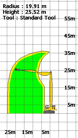
15 4.1 Operation within the Safe Working Envelope When the tool point is within green region of the envelope that means the machine is operating in the safe working region of the envelope as shown below. If the tool is within the stability envelope: The green LED will be lit 4.2 Approach to Stability Envelope When the tool point is in the yellow region of the envelope, it means that the machine is approaching the stability envelope. If the tool is approaching the stability envelope: The amber LED will be lit The internal alarm will sound The message shown here will be displayed.

16 4.3 Stability Envelope Exceeded When the tool is moved beyond the approach region, this indicates that the machine has exceeded beyond the stability envelope If the machine s approach has exceeded beyond the stability envelope: The red LED will flash The internal and external alarm will sound The message shown here will be displayed


17 4.4 Zooming In and Out The Zoom In button allows you to Zoom into the Stability envelope. The Zoom Out button allows you to Zoom out of the Stability envelope.

18 5 Display Options The Display Options button shows the display brightness, button click volume, language and the additional display settings can be adjusted from this menu. Select day / night mode ON OFF Adjust button click volume Additional Display Settings Exit to previous menu 5.1 Day / Night Mode Language selection To make viewing the display more comfortable at night, the display brightness can be switched to a preset night mode. The system will default to day mode on power up. Select day / night mode: Day mode ON Full display brightness Night mode ON Reduced display brightness
19 5.2 Select Language An appropriate language for the operator can be selected from this list. Exit without change Moves highlighter UP Accept highlighted language Moves highlighter DOWN

20 5.3 Additional Display Settings This submenu display some more additional display settings like Change machine colour, Change background, Auto-zoom On/Off, Tool Lock On/Off and Working proximity Indicator On/Off. Change background colour Select machine colour / type Select Auto Zoom ON OFF ON Select Tool Lock OFF Exit without change Working Proximity Indicator ON OFF


21 5.4 Select Machine Type Exit without change An appropriate machine type for the display can be selected from this list. 5.5 Change background colour Moves highlighter UP Moves highlighter DOWN Accept highlighted machine Change the background colour of the envelope.


22 5.6 Auto Zoom When the Auto Zoom function is switched on, it automatically moves the camera along with the tool point position and zooms in when the tool pin approaches the stability envelope. Please note when the auto zoom function is on, the Tool Lock button disappears. When the Auto Zoom function is switched off, it automatically moves the camera back to the original position. The Tool Lock button appears back in this case.


23 5.7 Tool Lock On/Off Pressing the Tool Lock button will lock the tool to the center of the graphic display. The tool will remain centrally positioned on the screen regardless of any machine movement. Press the button again to unlock the tool. Press the button again to unlock the tool.


24 5.8 Working Proximity Indicator On/Off Pressing the Working Proximity Indicator button will draw a line to warn if the machine cab is situated too close to the tool point in order to protect against falling debris. A warning message is shown if the machine cab is within the debris hazard area based on the height of the tool as given below. Press the button again to turn the working proximity indicator Off.
25 6 Test / Diagnostics The system test function is available from the main operating screen. This option allows the functionality of the system to be verified, and basic trouble-shooting to be performed. In this mode, the amber LED will flash to indicate that the system is in maintenance mode. The system will continue to monitor any machine safety status. Alarm conditions and warnings / controls will be issued as normal. The image shown is an example only. The exact contents of the sensor list will depend on machine type and PME specification. Exit to previous menu System information Code protected access to system set-up and calibration

26 6.1 System Information Information regarding the system can be found from this menu. License information Software Version information Distributor information Exit to previous menu Machine information
27 6.2 Time / Date Adjustment Time / date adjustment requires supervisor access rights. Adjust date Adjust time Adjust time zone Exit to previous menu

28 Time / Date Adjustment continued Cancel without change Moves highlighter to right / Hold to delete digit Cancel without change Moves highlighter to left / Hold to delete number Moves highlighter UP Increases highlighted digit Decreases highlighted digit Accept highlighted time zone Moves highlighter DOWN Accept displayed value

29 6.3 User Login User Login Setup Requires supervisor access rights. Select user to edit Add new user Select user to delete Edit user login code Exit to previous menu Select user(s) to be displayed on login screen


30 6.4 Radius/ Height Requires supervisor access rights. Boom = Boom pivot pin Artic = Artic pivot pin Arm = Arm pivot pin Tool Pin = Not used Tool Point = Current Tool Point Lift Point = Current lifting point 6.5 Pressure Transducers Exit to previous menu Boom Base PISTON - Full side Boom Base ROD - Rod side
31 7 Tool Selection Menu The system can be calibrated with no tools, one or multiple tools for use in any duty. If more than one tool has been calibrated, it will be manually selected via the Select tool selection screen shown below. Use the arrow buttons to select the required tool and confirm using the TICK button. Example tools are shown in the listing. Exit without change Moves highlighter UP Moves highlighter DOWN Accept highlighted Tool
32 8 Warning Messages 8.1 On Screen Messages Approaching Stability Envelope Stability Envelope Exceeded Maximum pressure exceeded Minimum pressure exceeded When the tool point approaches the stability envelope When the tool point reaches out of the stability envelope Furthest point of equipment has reached/exceeded set limit Pressure has reached/exceeded minimum set limit *The approach limit is configurable at point of calibration, check system operation before commencing work. PME continuously monitors the presence and condition of the safety controller and sensors. If the safety controller or any sensor fails an error message box will appear at the bottom of the display. In the event of a failure, the cab mounted beacon (if fitted) will indicate that the system is NOT active, the display red LED will flash and the internal and external alarms will sound.
. PME is subject to the WEEE directive, therefore PME or any component must be returned to Prolec Ltd for correct disposal or recycling.")
33 9 Taking Product out of Operation Prolec Limited is committed to complying with the upcoming European Directive of RoHS (Restriction of Certain Hazardous Substances) and WEEE (Waste from Electrical and Electronic Equipment). PME is subject to the WEEE directive, therefore PME or any component must be returned to Prolec Ltd for correct disposal or recycling. The display and safety controller are fitted with internal batteries and must not be disposed of in landfill. 10 Service and Repair PME has very few user serviceable parts. The safety controller has internal fuses that, in the event of a blown fuse, can be replaced. The service section describes daily, monthly and yearly checks that must be carried out to ensure safe operation of the system Maintenance Review Due to nature of the PME system operating environment, changes in usage can occur. Prolec Ltd must be notified of any changes in the pattern of use of the system for consideration. Any alterations or modifications to machine components which affect the system must be reported to Prolec Ltd or via the service agreement holder. To aid in the use of PME, all appropriate technical bulletins relating to PME are to be assessed and implemented as appropriate. This information is available from Prolec Ltd. Prolec Ltd must be informed of any Prolec system component failure via the service agreement holder. Technical consultation is available to the user, contact Prolec Ltd or the service agreement holder. Prolec Ltd Telephone +44 (0) Benson Road Fax +44 (0) Nuffield Industrial Estate service@prolec.co.uk Poole Dorset BH17 0GB
34 11 Definitions / Glossary Pitch Roll Boom Arm Artic Pivot pin Pressure transducer Full side Rod side Longitudinal base machine angle (fore / aft) Lateral base machine angle (side to side) First articulation connected to turret Second articulation Second articulation of a hydraulically adjustable boom (luffing boom, knuckle boom, two piece boom) Point at which the articulations rotate about Device to measure pressure within an hydraulic cylinder Internal section below the cylinder rod face Internal section above the cylinder rod face
35
36 Prolec Ltd is a James Fisher Company Prolec Ltd 25 Benson Road Nuffield Industrial Estate Poole England BH17 0GB Tel: +44 (0) service@prolec.co.uk
, Issue1.0, April 2013 PME 300 PME300+ Machine Envelope Controller. Operators Manual
 PME 300 PME300+ Machine Envelope Controller Operators Manual This guide describes operation of the PROLEC PME ENVELOPE SAFETY SYSTEM FOR CONSTRUCTION PLANT Model covered : PART No. MODEL Ref PME300 PME300
PME 200. Operators Manual. Rated Capacity Indicator, Machine Envelope Indicator Rated Capacity Controller, Machine Envelope Controller
 PME 200 Rated Capacity Indicator, Machine Envelope Indicator Rated Capacity Controller, Machine Envelope Controller Operators Manual This guide describes operation of the PROLEC PME LIFTING AND MACHINE
, Issue1.0, March PMERail Ultra. Rated Capacity Controller Machine Envelope Controller. Operators Manual
 PMERail Ultra Rated Capacity Controller Machine Envelope Controller Operators Manual This guide describes operation of the PROLEC PME LIFTING AND MACHINE ENVELOPE SAFETY SYSTEM FOR CONSTRUCTION PLANT Model
Heightmaster Tool Low
 Prolec Ltd., 25 Benson Road, Nuffield Industrial Estate, Poole, Dorset, England BH17 0GB Heightmaster Tool Low Operators Guide This guide describes operation of the PROLEC HEIGHTMASTER TOOL LOW Model
Rail Pro (ALO) user manual. Document reference: V2.0 October 2015
 user manual. Document reference: V2.0 October 2015") Rail Pro (ALO) user manual Document reference: 562620-000 V2.0 October 2015 This guide describes operation of the PROLEC PME LIFTING AND MACHINE ENVELOPE SAFETY SYSTEM FOR CONSTRUCTION PLANT Model covered
Rail Pro (ALO) user manual Document reference: 562620-000 V2.0 October 2015 This guide describes operation of the PROLEC PME LIFTING AND MACHINE ENVELOPE SAFETY SYSTEM FOR CONSTRUCTION PLANT Model covered
Issue 2.1. Prolec Ltd., 25 Benson Road, Nuffield Industrial Estate, Poole, Dorset, England BH17 0GB. Heightmaster.
 Prolec Ltd., 25 Benson Road, Nuffield Industrial Estate, Poole, Dorset, England BH17 0GB Heightmaster Operators Guide This guide describes operation of the PROLEC HEIGHTMASTER Model covered : MODEL NAME
Weighloader ADT user manual. Document reference: V2.0
 user manual Document reference: 560371-010 V2.0 Contents Page 1 Introduction 3 2 LCD Display 5 3 Weighing 6 3.1 Tare 6 3.2 Loading 6 4 Soft Keys 7 5 Menu Options 8 5.1 Settings 8 5.1.1 Display 8 5.1.2
W1258 LOAD MOMENT INDICATOR OPERATORS MANUAL. Version 1.0 Serial No.: 55M1258COE. United States Canada Great Britain
 W1258 LOAD MOMENT INDICATOR OPERATORS MANUAL Version 1.0 Serial No.: 55M1258COE United States Canada Great Britain Broken Arrow, OK Ste-Foy, Quebec East Sussex, Hastings Tel: 918-252-1957 Tel: 418-266-6600
TABLE OF CONTENTS TABLE OF CONTENTS... 1 MANUAL REVISION HISTORY... 2 IMPORTANT SAFETY NOTICE...
 TABLE OF CONTENTS TABLE OF CONTENTS... 1 MANUAL REVISION HISTORY... 2 IMPORTANT SAFETY NOTICE... 3 1.0 General Information... 5 1.1 System Components... 5 1.2 Specifications... 5 1.2.1 Torque Ranges...
RCI-8522 HRT and LM Systems Operator Manual MAN-1108 REV F
 HRT and LM Systems Operator Manual MAN-1108 REV F LSI-Robway Pty Ltd, 32 West Thebarton Road, Thebarton, South Australia, 5031 Phone: (+61 8) 8238 3500 Fax: (+61 8) 8352 1684 mail@robway.com.au www.lsirobway.com.au
DISCLAIMER & COPYRIGHT
 DISCLAIMER & COPYRIGHT ROAD ANGEL Group has made every effort to ensure that all the information contained in this manual is accurate and reliable. However, the information is subject to change without
Integriti User Manual. Elite / EliteX LCD Terminal Keypads
 Integriti User Manual Elite / EliteX LCD Terminal Keypads INNER RANGE recommends that all INTEGRITI systems are installed & maintained by FACTORY CERTIFIED TECHNICIANS. For a list of Accredited Dealers
i-reader User manual
 i-reader User manual Table of contents 1. Introduction...1 2. General description i-reader...1 3. Intended use...1 4. Safety and maintenance...1 5. Installing the i-reader...2 5.1 Power supply...2 5.2
Installation Instruction. HART Add-On Module
 - Translation Typs 17-A1Z0-0005, B7-A2Z0-0033 and G7-A0Z0-0007 Version for: Non hazardous areas ATEX/IECEx Zone 1 and Zone 2 UL Class I Division 1 and Division 2 Document No.: B1-A2Z0-7N0001 / 400570 Revision
PROXIMITY Encoding System
 PROXIMITY Encoding System ins-206 Date code: 251103 Contents 2 Contents Setting up the system...4 Introduction...4 What s in the box...5 Installing the system...5 Initialising the program...6 Initialising
or call
 User Guide DISCLAIMER & COPYRIGHT ROAD ANGEL Group Ltd has made every effort to ensure that all the information contained in this manual is accurate and reliable. However, the information is subject to
HST -TZ1 Guard-locking mechanism (Translation of Original Manual)
") Installation and Operating Manual for Components HST -TZ1 Guard-locking mechanism (Translation of Original Manual) HST-TZ1 Ident.-No.: 10234 HST-TZ1 Ident.-No.: 10236 HST-TZ1 Ident.-No.: 10235 HST-TZ1
Installation and Operating Manual for Components HST -TZ1 Guard-locking mechanism (Translation of Original Manual) HST-TZ1 Ident.-No.: 10234 HST-TZ1 Ident.-No.: 10236 HST-TZ1 Ident.-No.: 10235 HST-TZ1
LENGTH-ANGLE-RADIUS-LOAD INDICATING SYSTEM
 www.patamerica.com PAT America, Inc. LENGTH-ANGLE-RADIUS-LOAD INDICATING SYSTEM EI65/0005 OPERATOR S MANUAL P/N 056-065-190-005, Rev. C, 6/15/00 Operator s Manual EI65 / 0005 NOTICE The information in
Operating Instructions
 Innovative by tradition. Operating Instructions Control Unit SG-RSV 239 Version 1 1003986 SG-RSV 239/24 24 V= 1005372 SG-RSV 239/36 36 V= 1003271 SG-RSV 239 50-150 V= Mayser GmbH & Co. KG Örlinger Straße
TABLE OF CONTENTS TABLE OF CONTENTS... 1 IMPORTANT SAFETY NOTICE...
 TABLE OF CONTENTS TABLE OF CONTENTS... 1 IMPORTANT SAFETY NOTICE... 2 1.0 General Information... 3 1.1 System Components... 3 1.2 Specifications... 3 1.2.1 Torque Ranges... 3 1.2.2 Electrical Specifications...
Loadlog 8000i. On-Board Weighing System. Operation. RDS Part No.: Document Issue: Software Issue: S/DC/ : 17/1/08 PS rev.
 Loadlog 8000i On-Board Weighing System Operation RDS Part No.: Document Issue: Software Issue: S/DC/500-10-580 1.20 : 17/1/08 PS 312-001 rev. 09 CONTENTS Electromagnetic Compatibility (EMC) This product
Truckweigh. operators sheet STGGLOBAL.NET
 Truckweigh operators sheet 1300 998 784 STGGLOBAL.NET FRONT PANEL FUNCTIONALITY The various screens and menus are accessed using the four buttons located around the LCD display, described briefly below.
BORESCOPE INSTRUCTIONS INSPECTION CAMERA RANGE RBS100 RBS200 RBS300. Retain these instructions for future reference
 BORESCOPE INSPECTION CAMERA RANGE RBS100 RBS200 RBS300 INSTRUCTIONS Retain these instructions for future reference www.ringautomotive.co.uk 1 Instructions for Ring Automotive Borescope Inspection Camera
LOAD MOMENT INDICATOR SYSTEM MARK 4E/2
 LOAD MOMENT INDICATOR SYSTEM MARK 4E/2 01 18.1ft 4051lb 02 56.3 6850lb OPERATOR'S MANUAL P/N 031-300-190-073, Rev. D 05/30/2000 Operator's Manual / Mark 4E/2 NOTICE The information in this document is
DMX LED Starcloth Systems
 DMX LED Starcloth Systems User Manual Order codes: 3 x 2m with Stand & Bag Set (Black cloth, CW) - STAR01 2.2 x 1m DJ Skirt (Black cloth, CW) - STAR04 3 x 2m (Black cloth, CW) - STAR05 3 x 2m (White cloth,
SKIVING MACHINE MAINTENANCE & INSTRUCTIONS MANUAL ASSK2. Allswage UK. Roebuck Street, West Bromwich, B70 6RB
 SKIVING MACHINE ASSK2 MAINTENANCE & INSTRUCTIONS MANUAL A. WARRANTY AND RESPONSIBILITY Warranty: It's the supplier's responsibility to guarantee the conformity of the product, assuring that it's manufactured
DEEP SEA ELECTRONICS PLC DSE103 MK II Speed Switch Operators Manual
 DEEP SEA ELECTRONICS PLC DSE103 MK II Speed Switch Operators Manual Document number 057-135 Author : Paul Gibbons DSE103 MKII Operator Manual Issue 1 Deep Sea Electronics Plc Highfield House Hunmanby North
Chapter 1 General Information
 Chapter 1 General Information System Description Chapter 1 General Information 1.0 System Description The Affirm attaches to the Selenia Dimensions. A biopsy device attaches to the Affirm. X- and Y-axes
SDP:01. Scania Diagnos & Programmer 3. User instructions. Issue 1. Scania CV AB 2006, Sweden
 SDP:01 Issue 1 en Scania Diagnos & Programmer 3 User instructions Scania CV AB 2006, Sweden Contents Contents Introduction General... 3 Why SDP3?... 4 System requirements and ancillary equipment System
EU Driver s Hours Rules covered by Digifobpro. Table of contents
 EU Driver s Hours Rules covered by Digifobpro Digifobpro provides analysis of Driver Cards both in it s Quick View and Driver Card - Download features ( see Digifobpro Functions page 4). There follows
M-610 USER MANUAL PLEASE TAKE THE TIME TO READ THESE INSTRUCTIONS BEFORE STARTING TO USE THE SCALES
 M-610 USER MANUAL PLEASE TAKE THE TIME TO READ THESE INSTRUCTIONS BEFORE STARTING TO USE THE SCALES TABLE OF CONTENTS INTRODUCTION. 2 POWER SUPPLY. 4 INSTRUCTION FOR REPLACING BATTERIES 5 SPECIFICATIONS..
Polymer Electric. Operating Instructions. Control Unit SG-EFS 1X4 ZK2/1 8k2. Version 3
 Operating Instructions Control Unit SG-EFS 1X4 ZK2/1 8k2 Version 3 1003100 SG-EFS 104 ZK2/1 8k2 24 V=/~ 7500354 SG-EFS 134 ZK2/1 8k2 230 V~ Original instructions GmbH & Co. KG Polymer Electric Örlinger
RV LEVELING SYSTEM AUTO LEVEL SYSTEM WARNING! FAILURE TO ACT IN ACCORDANCE WITH THE FOLLOWING MAY RESULT IN SERIOUS PERSONAL INJURY OR DEATH.
 RV LEVELING SYSTEM AUTO LEVEL SYSTEM WARNING! FAILURE TO ACT IN ACCORDANCE WITH THE FOLLOWING MAY RESULT IN SERIOUS PERSONAL INJURY OR DEATH. THE USE OF THE GROUND CONTROL AUTO LEVELING SYSTEM TO SUPPORT
R9 U 13 SER GUIDE 7 R6 O22 O26 O32 R18 R24
 13 7 USER GUIDE 8 Introduction Thank you for purchasing this product. Your new headset has been developed using the latest technology, designed for comfort and freedom of movement. This headset is very
OPERATION ZONE SYSTEM DS 105 OPERATOR'S HANDBOOK DS 105 OPERATING HANDBOOK REV 1 03/13/96
 DS 105 i OPERATION ZONE SYSTEM DS 105 OPERATOR'S HANDBOOK DS 105 i NOTICE The information in this document is subject to change without notice. PAT makes no warranty of any kind with regard to this material,
Blitzer RGB Strobe. User Manual. Order code: EQLED365
 Blitzer RGB Strobe User Manual Order code: EQLED365 Safety advice WARNING FOR YOUR OWN SAFETY, PLEASE READ THIS USER MANUAL CAREFULLY BEFORE YOUR INITIAL START-UP! Before your initial start-up, please
HEX Par 9 MKII. Exterior Fixture User Manual. Order code: LEDJ226
 HEX Par 9 MKII Exterior Fixture User Manual Order code: LEDJ226 Safety advice WARNING FOR YOUR OWN SAFETY, PLEASE READ THIS USER MANUAL CARE- FULLY BEFORE YOUR INITIAL START-UP! Before your initial start-up,
PF LED Profile. User Manual
 PF LED Profile User Manual Order codes: ELUM094-100W 3200K WW Version ELUM095-100W 6000K CW Version ELUM096-150W 3200K WW Version ELUM097-150W 6000K CW Version Safety advice WARNING FOR YOUR OWN SAFETY,
Starlit Dance Floor. User Manual
 Starlit Dance Floor User Manual Order codes: 500W Power Supply - LEDJ405 750W Power Supply - LEDJ427 1000W Power Supply - LEDJ428 1500W Power Supply - LEDJ429 White Remote Control Pack - LEDJ406 White
Sliding shutter control Aluminium shutters
 Sliding shutter control Aluminium shutters Operating and maintenance instructions FOR THE USER Valid from 09.2011 E 916.3 Notes These operating instructions describe how to operate the EHRET sliding shutter
User Manual RINS1209-5
 User Manual 2x 2x RINS1209-5 The EURO mini Keypad Contents Introduction 1-5 Using EURO mini with PIN Codes 5-9 Intelligent Setting 10-11 When Problems Arise 12 Setting Individual Areas 13-14 Chime Facility
ivisibility (Keypad Operator Access Control Series) Lift Truck Onboard Automatic Detection / Recording of All Operational Downtime Events
 Lift Truck Onboard Automatic Detection / Recording of All Operational Downtime Events") Installation & Operational Manual ivisibility (Keypad Operator Access Control Series) Lift Truck Onboard Automatic Detection / Recording of All Operational Downtime Events ivisibility V2 General Installation
Installation & Operational Manual ivisibility (Keypad Operator Access Control Series) Lift Truck Onboard Automatic Detection / Recording of All Operational Downtime Events ivisibility V2 General Installation
Instruction Manual FB-606 FB-606 TF. Infrared Manual Remote Control. LJU Automatisierungstechnik GmbH
 Instruction Manual LJU Automatisierungstechnik GmbH TF Infrared Manual Remote Control LJU Automatisierungstechnik GmbH Am Schlahn 1 14476 Potsdam Germany Tel.: +49 (0) 33201 / 414-0 Fax: +49 (0) 33201
TELESCOPIC BOOM CRANES
 MICRO GUARD RCI 510 TELESCOPIC BOOM CRANES ORS Full 9.7 K CWT 360º Erected 60 TeleJib 17º AuxHd On Pick From Main Boom Front Winch SET UP MANUAL OUTLINE OF OPERATION SYSTEM COMPONENTS Microguard RCI 510
Control unit SG-EFS 104/4L. EN Operating instructions. Innovative by tradition. Version SG-EFS 104/4L AC/DC 24 V
 Innovative by tradition. Control unit SG-EFS 104/4L EN Operating instructions Version 2 1004128 SG-EFS 104/4L AC/DC 24 V Original instructions Mayser GmbH & Co. KG Örlinger Straße 1 3 89073 Ulm GERMANY
OPERATION MANUAL AND SPECIFICATION
 OPERATION MANUAL AND SPECIFICATION SINCE 1943 Keyboard layout... 2-3 How to connect the camera & charger... 4 How to use the coiler... How to adjust the camera light... 6 How to record a standard survey...
AIS. HELIX Accessory Guide TABLE OF CONTENTS. Overview... 5 Track AIS Targets... 5 AIS Target Overview... 7 Turn on Alarms... 8
 AIS HELIX Accessory Guide 532440-1_A TABLE OF CONTENTS Overview............................................. 5 Track AIS Targets...................................... 5 AIS Target Overview...................................
Elevation Window Control System
 Elevation Window Control System Keypad installation and user guide August 2013 copyright by ASSA ABLOY WARNINGS Read these instructions prior to the activation of the keypad. Save this user guide in a
GREISINGER electronic GmbH D Regenstauf, Hans-Sachs-Straße 26 phone: / , fax: / ,
 H55.0.21.6C-02 Operating Manual Precision Barometer from Version 1.0 GPB 3300 GREISINGER electronic GmbH D - 93128 Regenstauf, Hans-Sachs-Straße 26 phone: +49 9402 / 9383-0, fax: +49 9402 / 9383-33, email:
Operating console SLI system Manitex Telescopic Crane
 vscale D3 Operating console SLI system Manitex Telescopic Crane Contents Safety instructions 1 Product description 2 Installation / Wiring 3 Commissioning 4 Operation 5 Maintenance / Repair 6 Appendix
RGB Power Batten. User Manual. Order code: EQLED032
 RGB Power Batten User Manual Order code: EQLED032 Safety advice WARNING FOR YOUR OWN SAFETY, PLEASE READ THIS USER MANUAL CARE- FULLY BEFORE YOUR INITIAL START-UP! Before your initial start-up, please
Contents. Packing List. VILTA Mobile. Overview. Portable Bag. Quick Start. Charging Cable. Start Up. Lanyard. Specifications.
 www.freevisiontech.com Feel free to share your photos and videos with us and we might put them on our website. User Manual Facebook.com/FreevisionVILTA Twitter.com/FreeVisionVILTA instagram.com/freevision_vilta
HCU1 User Guide H A
 Page 1 of 13 HCU1 User Guide H-1000-5016-04-A Page 2 of 13 HCU1 disclaimers 2004-2005 Renishaw plc. All rights reserved. RENISHAW is a registered trademark of Renishaw plc. This document may not be copied
KINOVA OLED Display. User Guide
 KINOVA OLED Display User Guide TABLE OF CONTENTS DISCLAIMER... 3 ABOUT THIS DOCUMENT... 4 Symbols, definitions and acronyms... 4 GENERAL INFORMATION... 5 Marking and Label... 5 Disposal... 5 DIMENSIONS...
Rheinmetall Elektronik
 PAT America, Inc. Rheinmetall Elektronik DS350 MODULAR BOOM CONTROL EXTENSION FOR GROVE CRANE TMS/TTS 870 TROUBLESHOOTING MANUAL P/N 031-300-190-061 Rev. B 02/12/01 NOTICE The information in this document
Living. Keyfree Connected Smart Lock Manual. smart. The smarter way to protect your home
 smart Living Keyfree Connected Smart Lock Manual Please read the intructions before fitting and using the Keyfree Connected lock. The functions and design of this product can be changed without prior notice
Intrinsically safe batch controller Batching Master 110i
 Intrinsically safe batch controller Batching Master 110i Installation Guide BVS 04 AT E 172 Revision 12.2 IBS BatchControl GmbH Im Sträßchen 2-4 Tel.: ++49 2441 9199 801 53925 Kall Fax.: ++49 2441 9199
TABLE OF CONTENTS ADJUSTING YOUR LCD MONITOR
 TABLE OF CONTENTS ADJUSTING YOUR LCD MONITOR -------------- 2 General safety precautions. 2 Unpacking your monitor 5 Viewing angle 6 How to open the back cover 6 Connecting your monitor 7 User controls
GRUNDFOS INSTRUCTIONS. Control MPC. Installation and operating instructions
 GRUNDFOS INSTRUCTIONS Control MPC Installation and operating instructions English (GB) English (GB) Installation and operating instructions Original installation and operating instructions CONTENTS Page
Brivis Touch. Owner s Manual
 Brivis Touch Owner s Manual Congratulations on purchasing a Brivis Touch Comfort Controller. This intelligent Controller can be used with a range of Brivis heating and cooling products. The Brivis Touch
Operation Manual Locator Wöhler L 200
 Operation Manual Locator Wöhler L 200 Best.-Nr. 22849 2014-12-18. Contents Contents 1 General Information... 3 1.1 Operation Manual Information... 3 1.2 Notes in this manual... 3 1.3 Proper use... 3 1.4
Flexoled FTP3HP RGB LED DMX Driver
 Flexoled FTP3HP RGB LED DMX Driver User Manual + 12-24V DMX INPUT DMX OUTPUT DC IN (12A MAX) DMX ADDRESS & DIMMER SETTINGS SWITCH 10 11 12 DMX MODE DIMMING MODE BUILT-IN MODE LOAD 4A PER CHANNEL (12A MAX)
Product Manual ASL Document Ref.: U doc Issue: 04 complete, approved - Date: 16/08/10 Part Number: M0618_23
 Product Manual ASL Document Ref.: U-0618-0103.doc Issue: 04 complete, approved - Date: 16/08/10 Part Number: M0618_23 RCS01 RPA Transmitter Charging Station This equipment is designed and manufactured
Microbar COB System. User Manual. Order code: EQLED137
 Microbar COB System User Manual Order code: EQLED137 Safety advice WARNING FOR YOUR OWN SAFETY, PLEASE READ THIS USER MANUAL CARE- FULLY BEFORE YOUR INITIAL START-UP! Before your initial start-up, please
MOVEBAND Display. User Manual
 MOVEBAND Display User Manual Overview Features Track daily fitness activity including steps taken, distance covered, calories burned, etc. Track sleep quality including hours slept, time taken to fall
Be sure to always check the camera is properly functioning, is properly positioned and securely mounted.
 Please read all of the installation instructions carefully before installing the product. Improper installation will void manufacturer s warranty. The installation instructions do not apply to all types
USER GUIDE. for. EkoTek Pager
 USER GUIDE for EkoTek Pager 9261-8275 Issue 5 CONTENTS Introduction 3 Compliance 5 General user information 6 EkoTek system schematic 7 Switching on the pager 8 Status and warning messages 8 Using menus
Operating Instructions Differential Pressure Transducer PS27
 Operating Instructions Differential Pressure Transducer PS27 halstrup-walcher GmbH Stegener Straße 10 79199 Kirchzarten/Germany Phone: +49 (0) 76 61/39 63 0 Fax: +49 (0) 76 61/39 63 99 E-mail: info@halstrup-walcher.com
Podium Data Analysis Software. User Manual. SWIS10 Version
 SWIS10 Version Issue 1.00 March 2003 Contents 1 Introduction 5 1.1 What is Podium? 5 1.2 About This Manual 5 1.3 Typographical Conventions 6 1.4 Getting Technical Support 6 2 Getting Started 7 2.1 System
English. Zeppelin Mini
 English Zeppelin Mini Welcome and thank you for choosing Bowers & Wilkins. When John Bowers first established our company he did so in the belief that imaginative design, innovative engineering and advanced
Get set, go! Getting to know your go! stick USB modem. The package of your ACN go! stick contains the following items:
 Quick Start Guide Get set, go! Welcome to ACN Mobile Broadband. This guide details the simple steps to install your go! stick USB modem and connect to the Internet - you ll be up and running in no time!
Gobo Projector XP 80W
 Gobo Projector XP 80W User Manual Order code: EQLED084 Safety advice WARNING FOR YOUR OWN SAFETY, PLEASE READ THIS USER MANUAL CARE- FULLY BEFORE YOUR INITIAL START-UP! Before your initial start-up, please
Quick Start. i16 w16 i8 w8 i6 i4 w4 i2 w2. 25W max. 42W max. Input 24V AC/DC 12/24V AC/DC 12/24V AC/DC 12/24V AC/DC
 Quick Start Safety Information: White Light and IR Variants (850nm & 940nm) Caution Risk Group 2. Avoid Exposure / use protection. See Safety Information in FULL Instruction Guide for details. Box Contents:
Pressure Transmitter and Reader of the PT-RF Series Manual
 Local Solutions For Individual Customers Worldwide Pressure Transmitter and Reader of the PT-RF Series Manual Contents 1 Safety instructions... 3 1.1 Intended use... 3 1.2 Specialist personnel... 3 1.3
Control unit SG-EFS 104/2W. EN Operating instructions. Innovative by tradition. Version SG-EFS 104/2W 24 V=/~
 Innovative by tradition. Control unit SG-EFS 104/2W EN Operating instructions Version 0.9 1005196 SG-EFS 104/2W 24 V=/~ Original instructions Mayser GmbH & Co. KG Örlinger Straße 1 3 89073 Ulm GERMANY
Colour Graphic Terminal User Manual. Rev 3.1
 Integriti. Colour Graphic Terminal User Manual. 1 Colour Graphic Terminal User Manual. Rev 3.1 2013-2014. Inner Range Pty. Ltd. Part Number: 636000U 2 Integriti. Revision 3.1 June 2014. SYSTEM DETAILS
The following steps will allow you to install and quickly begin using DevCom:
 QUICK START DevCom uses Device Descriptions (DDs) to access data stored in the memory of the smart field device. These DDs are developed by the manufacturer for their products and, in turn, distributed
Crossfire. User Manual. Order code: EQLED061
 Crossfire User Manual Order code: EQLED061 Safety advice WARNING FOR YOUR OWN SAFETY, PLEASE READ THIS USER MANUAL CAREFULLY BEFORE YOUR INITIAL START-UP! Before your initial start-up, please make sure
IRIS516. User Guide. Compact Marine PTZ Controller
 IRIS516 Compact Marine PTZ Controller User Guide Version 1.00. February 2013. Iris Innovations Limited. www.boat-cameras.com. info@boat-cameras.com 1/21 Contents: Page 3 Warnings and Regulatory Information
Hygro-/Thermometer. Operating Manual GFTH 95
 H53.0.X1.6C-07 Hygro-/Thermometer Operating Manual GFTH 95 WEEE-Reg.-No. DE93889386 GHM Messtechnik GmbH Standort Greisinger Hans-Sachs-Str. 26 D-93128 Regenstauf +49 (0) 9402 / 9383-0 +49 (0) 9402 / 9383-33
ACTpro Single Door IP Controller. Operating & Installation Instructions
 ACTpro 1500 Single Door IP Controller Operating & Installation Instructions 18-00079 Issue 1 This manual refers to the ACTpro 1500 a TCP/IP based control unit supporting up to 32 doors. Access Control
Explosion-Protected Arc-Fault Protection ExAFCI Arc-Fault Circuit Interrupter
 Installation, Operation & Maintenance Sheet Explosion-Protected Arc-Fault Protection ExAFCI Arc-Fault Circuit Interrupter > Contents 1 Contents 1 Contents...2 2 General Information...2 2.1 Manufacturer...2
Agility 2-Way Wireless Slim Keypad
 Agility 2-Way Wireless Slim Keypad Models: : RW132KL1, RW132KL1P Instruction Manual Agility 2-Way Wireless Slim Outdoor Keypad Table of Contents INTRODUCTION 3 MAIN FEATURES 3 COMMUNICATION SETUP 3 MOUNTING
Gemini Profiler with Survey Software
 0695-SOM-00008, Issue: 02 1 Tritech International Ltd. QPS QINSy 0695-SOM-00008, Issue: 02 Tritech International Ltd The copyright in this document is the property of Tritech International Ltd. The document
Installation instructions Inclination sensor EC2019 EC / / 2013
 Installation instructions Inclination sensor UK EC219 EC245 739215 / 3 1 / 213 Inhalt 1 Safety instructions 3 2 Mounting 4 3 Electrical connection 4 4 Dimensions 4 5 Technical Data 5 6 Characteristics
BOWMONK 2000 OPERATING MANUAL
 BOWMONK 2000 OPERATING MANUAL BOWMONK 2000 Components Pedal Force Transducer: The Pedal Force Transducer (PFT) is a strain gauge sensor that shows the forces necessary to stop the vehicle in Newton. Connect
Installation and Setup guide VARIO Series
 Installation and Setup guide VARIO Series VARIO w8 Contents VARIO i8 VARIO w4 VARIO i4 VARIO w2 VARIO i2 Page 2 Pages 3-4 Page 5 Page 6 Page 7 Page 8 Page 9-11 Quick Set-Up and Factory Defaults Complete
BatteryCheck USER MANUAL BATTERY MANAGEMENT TECHNOLOGY THAT POWERS YOUR ADVENTURES.
 BatteryCheck USER MANUAL BM PRO - 19 Henderson Road, Knoxfield 3180, Victoria, Australia Phone +61 3 9763 0962 Fax +61 3 9763 8789 Email sales@teambmpro.com Web www.teambmpro.com BATTERY MANAGEMENT TECHNOLOGY
HST -TS1 Guard-locking mechanism (Translation of Original Manual)
") Installation and Operating Manual for Components HST -TS1 Guard-locking mechanism (Translation of Original Manual) HST-TS1 Ident.-No.: 10250 HST-TS1 Ident.-No.: 10252 HST-TS1 Ident.-No.: 10251 HST-TS1
Installation and Operating Manual for Components HST -TS1 Guard-locking mechanism (Translation of Original Manual) HST-TS1 Ident.-No.: 10250 HST-TS1 Ident.-No.: 10252 HST-TS1 Ident.-No.: 10251 HST-TS1
Alu HEX Par 64. (12 x 12W six-colour LEDs RGBWAUV) User Manual. Order code: ELUM114
 User Manual. Order code: ELUM114") Alu HEX Par 64 (12 x 12W six-colour LEDs RGBWAUV) User Manual Order code: ELUM114 Safety advice WARNING FOR YOUR OWN SAFETY, PLEASE READ THIS USER MANUAL CARE- FULLY BEFORE YOUR INITIAL START-UP! Before
Alu HEX Par 64 (12 x 12W six-colour LEDs RGBWAUV) User Manual Order code: ELUM114 Safety advice WARNING FOR YOUR OWN SAFETY, PLEASE READ THIS USER MANUAL CARE- FULLY BEFORE YOUR INITIAL START-UP! Before
Link-Belt MG-540. Rated Capacity Indicator System. Calibration
 Link-Belt MG-540 Rated Capacity Indicator System Calibration Contents Where To Go For Help... 1 Introduction... 2 Required Tools... 2 Number Conversion... 2 Number Entry... 3 The Display... 5 Error Codes...
LASERMET SLIMJIM LED SIGN INSTRUCTION MANUAL LEDS-SJ XXX
 LASERMET SLIMJIM LED SIGN INSTRUCTION MANUAL LEDS-SJ 00843-00-XXX 00843-53-000 Page 1 of 11 Issue 3 2 January 2013 Lasermet SlimJim Illuminated Sign Instruction Manual Contents Introduction... 4 Installation...
iscout expert compact
 iscout expert compact Graphics console Contents General Information Important Notes System Description Configuration Setup Inspection checks before start-up Service and Maintenance Troubleshooting Appendix
FULL HD 1080P DASH CAM
 Value you can trust FULL HD 1080P DASH CAM Owners/Instruction Manual PLU 557209 Product overview Thank you for purchasing the SCADVR18 FULL HD 1080P Dash Cam. This Dash Cam is specifically designed for
ZF LED Zoom Fresnel. User Manual
 ZF LED Zoom Fresnel User Manual Order codes: ELUM090-100W 3200K WW Version ELUM091-100W 6000K CW Version ELUM092-150W 3200K WW Version ELUM093-150W 6000K CW Version Safety advice WARNING FOR YOUR OWN SAFETY,
PowerView Model PV780. Operations Manual Section 78
 PowerView Model PV780 Operations Manual 00-02-0859 2013-03-19 Section 78 In order to consistently bring you the highest quality, full featured products, we reserve the right to change our specifications
QUICK START USER GUIDE. Data Logger Model L452
 QUICK START USER GUIDE Data Logger Model L452 Statement of Compliance Chauvin Arnoux, Inc. d.b.a. AEMC Instruments certifies that this instrument has been calibrated using standards and instruments traceable
Thank you for selecting Instrument Technology, Inc. (ITI) to fulfill your remote viewing needs.
 to fulfill your remote viewing needs.") INTRODUCTION Thank you for selecting Instrument Technology, Inc. (ITI) to fulfill your remote viewing needs. Since 1967, ITI has been the Leader in Remote Viewing. ITI consistently provides cutting edge
INTRODUCTION Thank you for selecting Instrument Technology, Inc. (ITI) to fulfill your remote viewing needs. Since 1967, ITI has been the Leader in Remote Viewing. ITI consistently provides cutting edge
I. PRODUCT DESCRIPTION
 EP662 CAR DASH CAM INSTRUCTION MANUAL PLEASE READ THE MANUAL BEFORE YOUR FIRST USE. KEEP THIS MANUAL SAFE FOR FUTURE REFERENCE! GERMAN IS THE MENU LANGUAGE BY DEFAULT. TO FACILITATE THE SETTING FUNCTIONS,
Temperature & Humidity Datalogger
 R6030 Temperature & Humidity Datalogger Instruction Manual Table of Contents Introduction... 2 Product Quality... 3 Safety... 3 Features... 3 Included... 3 Specifications... 4 Instrument Description...