LIN2CAN & Configuration Tool
|
|
|
- Tamsin Baldwin
- 6 years ago
- Views:
Transcription

1 LIN2CAN & Configuration Tool MANUAL ENGLISH
2 HMS Technology Center Ravensburg GmbH Helmut-Vetter-Straße Ravensburg Germany Tel.: Fax: Internet: info-ravensburg@hms-networks.de Support For problems or support with this product or other HMS products please request support at Further international support contacts can be found on our webpage Copyright Duplication (copying, printing, microfilm or other forms) and the electronic distribution of this document is only allowed with explicit permission of HMS Technology Center Ravensburg GmbH. HMS Technology Center Ravensburg GmbH reserves the right to change technical data without prior announcement. The general business conditions and the regulations of the license agreement do apply. All rights are reserved. Registered trademarks All trademarks mentioned in this document and where applicable third party registered are absolutely subject to the conditions of each valid label right and the rights of particular registered proprietor. The absence of identification of a trademark does not automatically mean that it is not protected by trademark law. Document number: Version: 2.1
3 Content 1 General Definitions, Acronyms, Abbreviations Overview Support Returning Hardware LIN2CAN Device Description Features Pin Allocation Supply Voltage Serial Port RS CAN High-Speed CAN Low-Speed/LIN CAN Bus Terminal LIN Pull-Up Resistor LED Displays Installation and Start System Requirements Installation Connecting the LIN2CAN Gateway Starting the LIN2CAN Configuration Tool Operating Modes LIN-CAN-Gateway LIN-CAN-Gateway Master/Slave LIN-CAN-Gateway Slave LIN LIN Master/Slave LIN Slave LIN-PC-Interface Master/Slave Slave Monitoring Power Down mode Configuration of the Operating Modes Overview Configuring the Device LIN2CAN Manual, Version 2.1
4 Content 5.3 Tab General Tab LIN Message Config Tab Gateway Tab Master Tab Slave Tab LIN Monitor Error Overview LIN Messages Menu Reference Status Bar XML Configuration File LIN Messages Log File Extract of a Log in Tabular Form Extract of a Log as an ASCII File Technical Data Notes on EMC FCC Compliance EC Declaration of Conformity LIN2CAN Manual, Version 2.1
5 General 1 General 1.1 Definitions, Acronyms, Abbreviations CAN HTML L2CAPI LDF LIN LIN- message XML 1.2 Overview Controller Area Network Hypertext Markup Language LIN2CAN API (Programming interface) LIN Description File Local Interconnect Network Data telegram of the LIN bus. A data telegram consists of an 8-bit identifier field and an up to 8-byte data field. Extensible Markup Language This handbook is intended to familiarize you with your LIN2CAN Gateway. Please read this handbook before beginning the installation. The LIN2CAN Configuration Tool (L2C_Cfg_Tool.EXE) is used for configuration and commissioning of the LIN2CAN Gateway. A simple LIN monitor is integrated in the configuration program that displays LIN messages and errors on the bus. Once created, a configuration can be exported to an XML file. This file can be changed and imported again in order to reload the configuration onto a device. 1.3 Support For more information on our products, FAQ lists and installation tips, please refer to the support area on our homepage ( There you will also find information on current product versions and available updates. 1.4 Returning Hardware If it is necessary to return hardware to us, please download the relevant RMA form from our homepage and follow the instructions on this form. 5 LIN2CAN Manual, Version 2.1

6 LIN2CAN Device Description 2 LIN2CAN Device Description The LIN2CAN Gateway is a universal device for analyzing LIN networks via the CAN bus, and for emulating LIN Slave or LIN Master modules. The device can also be used as a LIN-PC-interface with PC configuration and monitoring software or for PC-compatible LIN device development (for a description of the operating modes see chapter 4, Operating Modes). 2.1 Features Power supply 7 to 16 V DC, Industrial 10 to 32 V DC Standby power consumption < 1 ma LIN bus interface via the LIN Transceiver TJA1020 CAN high-speed bus interface according to ISO/IS with galvanic isolation CAN low-speed bus interface according to ISO (Fault Tolerant) Serial port (RS232) for Gateway configuration 16 bit microcontroller LIN Master and Slave operation possible 2.2 Pin Allocation X1 X4 LED X2 X3 Fig : Pin allocation 6 LIN2CAN Manual, Version 2.1
7 LIN2CAN Device Description Supply Voltage The device is supplied at connector X1 with a DC voltage of 7 V to 16 V (Industrial 10 V to 32 V). A prefabricated cable for the power supply is included in the scope of delivery. Pin No. X1 Signal Lead color 1 + White 2 - Brown 3 GROUND Shield Table 2.2-1: Pin allocation Power Serial Port RS232 The signals of the serial port are connected to the 9-pin Sub-D connector X2. Pin No. X2 Signal 1 DCD 2 RX 3 TX 4 DTR 5 GND 6 DSR 7 RTS 8 CTS 9 RI Table 2.2-2: Pin allocation RS Shield Shield Table 2.2-3: Pin Mapping Null Modem Cable 7 LIN2CAN Manual, Version 2.1
8 LIN2CAN Device Description CAN High-Speed The signals of the CAN bus interface according to ISO/IS are connected to the 9-pin Sub-D connector X3 (see Table 2.3-3). Pin No. X3 Signal 1-2 CAN Low 3 GND CAN High Table 2.2-4: Pin allocation CAN HS CAN Low-Speed/LIN The bus interface according to ISO/IS (Fault Tolerant) and the LIN bus interface are connected to the 9-pin Sub-D connector X4. Pin No. X4 Signal 1 LIN 2 CAN Low 3 GND CAN High Table 2.2-5: Pin allocation CAN LS/LIN 2.3 CAN Bus Terminal There is no bus terminal resistor for the CAN bus assembled on the LIN2CAN Gateway. 8 LIN2CAN Manual, Version 2.1
9 2.4 LIN Pull-Up Resistor LIN2CAN Device Description The LIN2CAN has a 1 kohm pull-up resistor. The pull-up resistor is automatically activated in LIN Master Mode and automatically deactivated in LIN Slave Mode. External pull-up resistors are not necessary. 2.5 LED Displays The LIN2CAN Gateway has four 2-color LEDs. LED Status Meaning PWR Green flashing (1 Hz) Device active (Power) Short red flashing No configuration data read out of or written onto the Flash. Off Device in Power Down mode CAN Green flash CAN message successfully received or transmitted Red flash CAN message not transmitted or overrun in CAN Receive queue Red CAN Controller in bus off status Off No CAN message traffic LIN Green flash LIN message successfully received or transmitted Red flash LIN error while receiving or transmitting a LIN message Off No LIN message traffic SER (Serial) Green flash Data traffic between PC and LIN2CAN Gateway Off No data traffic Table 2.4-6: Meaning of the LED displays 9 LIN2CAN Manual, Version 2.1
10 Installation and Start 3 Installation and Start 3.1 System Requirements The LIN2CAN Configuration Tool has the following PC-system requirements: Pentium II or higher (500 MHz recommended) Windows 2000, Windows XP, Windows 7 one free RS232 interface 3.2 Installation (1) To install the LIN2CAN Configuration Tool and the programming interface (L2CAPI), insert supplied program CD in CD drive. (2) To start the installation program, run file L2C_Configtool_Setup.exe. 3.3 Connecting the LIN2CAN Gateway To connect the device to the PC, a serial, fully wired, crossed cable (null modem cable) and one free RS232 interface are required. 3.4 Starting the LIN2CAN Configuration Tool (1) Disconnect voltage supply of the device. (2) Connect device to the PC with RS232 line. (3) Reconnect voltage supply of the device Device detects PC and starts in PC interface mode. (4) Start Configuration Tool (L2C_Cfg_Tool.exe). (5) Select RS232 interface in use in menu Device Options. (6) Select baud rate according to HW version in menu Device Options: HW version 1.x baud rate = HW version 2.x baud rate = (7) To establish a connection to the device, click on LED in toolbar or select menu Device Connect. 10 LIN2CAN Manual, Version 2.1
11 Operating Modes 4 Operating Modes The LIN2CAN Gateway supports various operating modes: LIN-CAN-Gateway Master/Slave Slave LIN Master/Slave Slave LIN-PC-Interface Master/Slave Slave In every operating mode the LIN2CAN can be operated in Master/Slave or in Slave mode. All operating modes are configured via the PC. LIN and LIN-CAN-Gateway operating modes are configured via the PC as startup mode. If the device is not connected to a PC during power-on, it starts in the configured startup mode and works in standalone mode. If the device is connected by a serial cable to a PC during power-on, it starts in LIN-PC-Interface Slave mode. 4.1 LIN-CAN-Gateway The LIN-CAN-Gateway mode allows operating as LIN-CAN-Gateway Master/Slave or Slave and therefore the transparent transmission of LIN messages to a CAN network. Received LIN messages are transmitted to CAN. LIN identifiers are translated into CAN identifiers and the data of the message are passed on via the CAN object. The device also provides a transmit function on LIN via CAN. Here CAN identifiers are translated into LIN identifiers and transmitted once on request by a LIN Master (internal schedule table or external master) in the LIN network. The data of the CAN object are stored in a buffer and then transmitted as LIN message. A PC-configurable gateway table is available for the translation of messages, which is stored on the device. In addition it is possible to map errors occurring on the LIN bus (e.g. timeout according to LIN header) onto a CAN message. The gateway functionality can be activated and deactivated via CAN. A CAN object can be specified, whose first data byte is interpreted as a switch. If the content of this data byte is zero, the gateway functionality is switched off. If a value other than zero is received, the gateway functionality is switched on again.. 11 LIN2CAN Manual, Version 2.1
12 Operating Modes The Gateway table consists of a total of 67 entries, with LIN identifier, LIN error, gateway on/off or schedule table switching, a translation regulation and CAN identifier. The following options are available for the translation regulation: none There is no translation for this LIN message. LIN to CAN If a certain LIN message is received, its data are sent with the specified CAN identifier as a CAN message on the CAN bus CAN to LIN If the CAN object is received with the specified CAN identifier, its data are held in a buffer and activated on the LIN bus on request. The gateway functionality is available for both 11 bit and 29 bit identifiers. For further information see chapter Tab Gateway, p LIN-CAN-Gateway Master/Slave The device acts as a LIN Master/Slave, which means as a LIN bus arbiter with LIN Slave function. Several configurable schedule lists are available, whereas only one is processed cyclically. For further information about the schedule table see chapter Tab Master, p. 22. The active schedule table can be switched via CAN. For this, a CAN object can be specified, whose first data byte is interpreted as the number of the schedule table. If the requested schedule table does exists it is activated after processing of the current one LIN-CAN-Gateway Slave The LIN-CAN-Gateway Slave mode allows the transparent transmission of LIN messages to a CAN network. The device acts as a LIN-Slave. When a configured LIN header is received, the device executes the corresponding action defined in the action table (for further information see chapter Tab Slave, p. 23). 4.2 LIN LIN operating is possible as LIN-Master/Slave or LIN Slave LIN Master/Slave As LIN Master/Slave, the device works as a standalone LIN bus arbiter with LIN Slave function. A configurable schedule list is processed cyclically. The Slave function provides a transmit function via a configurable transmit buffer. For further information about the schedule list see chapter Tab Master, p LIN Slave The LIN Slave mode provides a standalone LIN Slave emulation. The device has a configurable transmit table. When a LIN identifier of a LIN bus master is received, the stored data are transmitted (for further information see chapter Tab Slave, p. 23). 12 LIN2CAN Manual, Version 2.1
13 4.3 LIN-PC-Interface Operating Modes The LIN2CAN Gateway can be operated as LIN-PC-Interface via the serial port, either as a LIN Master/Slave or as a LIN Slave Master/Slave As a LIN-PC-Interface Master/Slave, it is possible on the PC-side to initiate the LIN bus arbiter function or switch complete LIN messages. The whole LIN bus traffic can be read by the PC via an additional monitoring function. In addition it is possible to switch a wakeup signal (duration ms) to the bus. With this mode it is possible with the aid of the L2CAPI to implement a PC-based LIN Master. THE L2CAPI has no access to CAN Slave Monitoring In this mode the device can work as a LIN Slave with a dynamic transmit buffer. It is possible to monitor and evaluate the LIN message traffic with the monitoring function. 4.4 Power Down mode The LIN2CAN supports a Power Down mode for the standalone modes. (The device must not be connected to the PC via a serial cable). After a configurable time without bus traffic on LIN or CAN, the Power Down mode is activated. The device wakes up automatically when there is communication on LIN or CAN or when the serial lead is plugged in. 13 LIN2CAN Manual, Version 2.1

14 Configuration of the Operating Modes 5 Configuration of the Operating Modes The following section describes the configuration of the device with the LIN2CAN Configuration Tool. 5.1 Overview The Configuration Tool is divided into six tabs. The most important settings, like CAN and LIN transceiver settings, start-up mode, device name and version information are displayed below the tab area. Fig : Overview Configuration Tool 14 LIN2CAN Manual, Version 2.1
15 5.2 Configuring the Device Configuration of the Operating Modes (1) Connect LIN2CAN Gateway to the PC with serial null modem cable. (2) Connect device to voltage supply. (3) In the Configuration Tool in menu Device Options define COM port to which the LIN2CAN Gateway is connected. Set baudrate for devices with hardware version 2.0 and newer to Baud, for older devices set to Baud. (4) To establish a connection to the device, click on red LED in toolbar or select menu Device Connect. (5) Select menu Device Read Config to read configuration from the device (optional). (6) It is now possible to change the configuration or to open an existing configuration. (7) To store the configuration in the LIN2CAN Gateway, select menu Device Write Config. (8) The configuration can also be stored as XML. (9) To terminate connection to the device, click on green LED in toolbar or select menu Device Disconnect. Note: If standalone mode is set (after start-up), the operating mode is active only after removing the serial cable and a brief interruption of the voltage supply of the LIN2CAN Gateways. 15 LIN2CAN Manual, Version 2.1

16 5.3 Tab General Configuration of the Operating Modes The tab General shows the general configuration independently of the mode. Fig : Tab General Device Information The Device Information frame shows the device identification, a 15-figure alphanumerical value and the firmware and hardware version of the connected device. Communication Parameters The LIN and CAN baud rates and the mode of the CAN transceiver are set in the Communication Parameter frame via dropdown menus. For LIN baud rates of 2400 bauds, 9600 bauds and bauds are available. For CAN the following baud rates and transceiver modes can be selected: 16 LIN2CAN Manual, Version 2.1
17 Configuration of the Operating Modes CAN baudrate [kbaud] CAN transceiver mode 10 Low-speed/high-speed 20 Low-speed/high-speed 50 Low-speed/high-speed 100 Low-speed/high-speed 125 Low-speed/high-speed 250 high-speed 500 high-speed 1000 high-speed Table 5.3-1: Overview CAN baud rate and Transceiver mode Only valid combinations of CAN transceiver mode and CAN baud rate can be entered. Device Management In the Device Management frame you have the possibility to select the Startup Mode (see chapter 4), the time until the device goes into energy saving mode (Power down after, see chapter 4.7) and the Device Timer (for timestamp generation of received LIN messages) can be set. The Device Timer function is only useful in conjunction with the LIN PC Interface Mode (see chapter 4.6). The time set here is used as a start value for the timestamp generation of received LIN messages. With enabled checkbox always on the LIN2CAN stays active and does not go in energy saving mode (power down inactive). 17 LIN2CAN Manual, Version 2.1

18 5.4 Tab LIN Message Config Configuration of the Operating Modes This tab is used for assignment of the LIN data length and CRC type to the LIN identifier. The length between 1-8 data bytes can be set for each LIN identifier. The LIN specification version 1.2 and higher regards the length information in the identifier as optional which can be replaced by LDF definitions. In this way LIN identifier independent data length are possible. The CRC type can be chosen between CRC type according to LIN specification 1.3 or 2.0. Fig : Tab LIN Message Config 18 LIN2CAN Manual, Version 2.1
19 Configuration of the Operating Modes The standard LIN data length and the standard CRC type is set automatically while creating a new configuration. LIN identifier Standard data lengths (Bytes) Standard CRC type 0x00-0x1F 2 LIN Spec x20-0x2F 4 LIN Spec x30-0x3F 8 LIN Spec. 1.3 Table Overview LIN identifier standard data length and CRC types Note: Make sure, that the respective LIN identifier is configured to the same data length and CRC type for all LIN nodes in the whole LIN network. Otherwise the communication cannot be assured. 19 LIN2CAN Manual, Version 2.1

20 Configuration of the Operating Modes 5.5 Tab Gateway The tab Gateway is used for configuration of the Gateway mode of the device and includes the translation table for the conversion of LIN identifiers to CAN identifiers and back. Fig : Tab Gateway A translation table consists of the following entries and translation possibilities: 64 entries for LIN identifiers Translation: none, LIN to CAN or CAN to LIN 1 entry for LIN errors Translation: none or LIN to CAN 1 entry for gateway on/off Translation: none or CAN to LIN 1 entry for schedule table switching Translation: none or CAN to LIN 20 LIN2CAN Manual, Version 2.1
21 Configuration of the Operating Modes If the translation regulation is altered, a CAN identifier is automatically allocated: none no CAN identifier LIN to CAN 0x100 + LIN identifier CAN to LIN 0x200 + LIN identifier For LIN errors and gateway on/off 0x40 is added in each case, for schedule switching 0x41. The CAN identifier can be altered. Make sure, that the identifiers correspond to the frame format set. An empty box for the CAN identifiers or multiple use of a CAN identifier are not permitted. The setting for the CAN frame format influences the whole table. Switching from Extended to Standard is only possible if there are no CAN identifiers in the Extended frame format in the table. 21 LIN2CAN Manual, Version 2.1
 is entered.")
22 5.6 Tab Master Configuration of the Operating Modes The tab Master contains the schedule list for the LIN Master/Slave and the LIN Gateway Master/Slave mode. Each of the 16 lists has space for 64 entries. Fig : Tab Master In the schedule list LIN identifier and the waiting time after transmission of this LIN message (0 to 255 ms) is entered. The transmit table consists of 64 entries, one for each possible LIN identifier. Input of the waiting time is only possible if a LIN identifier is entered. If the LIN identifier is removed (via an empty input), the waiting time is also removed. Up to 16 schedule tables can be configured and saved in XML. Only the number showed beside the schedule table number can be stored in the device. In the Master/Slave mode the schedule table 0 is always active. Only in the Gateway Master/Slave mode the active schedule table can be switched via CAN. 22 LIN2CAN Manual, Version 2.1

23 5.7 Tab Slave Configuration of the Operating Modes The tab Slave is used for the configuration of the action tables in the LIN Slave, LIN Master/Slave and LIN PC Interface Slave modes. The table is only implemented once on the device and determines which action is executed when the configured LIN header is received. Fig : Tab Slave with action table In the action table for every LIN identifier either the action Ignore or Send LIN Data can be stored. With Ignore, the LIN2CAN Gateway shows no reaction when receiving the relevant identifier. In column Data no data can be entered. With Send LIN Data the data field for the LIN identifier is automatically filled with NULL data bytes. The data bytes are entered as hexadecimal value. The data bytes are separated by spaces. The number of data bytes depends on the setting in tab LIN Message Config. If the length is modified in this tab, the data length in tab Slave is adapted, too. In case of decreasing the data length the last data bytes are removed, in case of increasing the data length zeros are added at the end. 23 LIN2CAN Manual, Version 2.1
 is valid, i.e. if a LIN ID with an assigned action is received, this action is executed.")
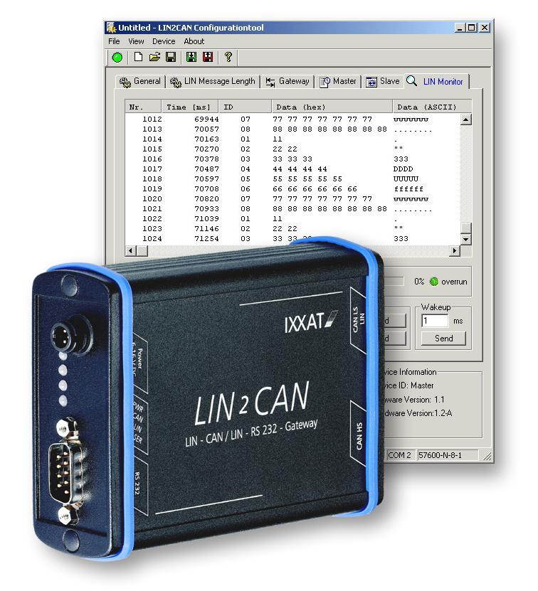
24 Configuration of the Operating Modes 5.8 Tab LIN Monitor The tab LIN Monitor is used for monitoring the data traffic on the LIN bus in the LIN PC Interface mode. The action table (see in tab Slave) is valid, i.e. if a LIN ID with an assigned action is received, this action is executed. LIN identifiers, complete LIN messages or a wakeup signal can be transmitted. The mode must be set to LIN PC Interface Master/Slave using the Radio button. There must not be a second LIN Master in the LIN network, as this leads to collisions of the messages. The transmitted messages and errors on the LIN bus are displayed in the monitor. Fig : Tab LIN Monitor The monitor provides the following operating and display elements: 1) Monitor window: Table holds up to 3000 LIN messages.13 messages can be displayed simultaneously in the window. Column Nr.: sequence number of the LIN message Column Time (ms): receiving timestamp (start of device in milliseconds) Column ID: LIN identifier or remark Err for error Columns Data Hex/Data ASCII: LIN data of LIN message or error code for LIN error message Column Error Description: plain text of an error message 24 LIN2CAN Manual, Version 2.1
25 Configuration of the Operating Modes 2) Start/Stop Button: Controls entry of the LIN messages in the monitor window. 3) Log Button: Opens the window for selection of the Log file, in which the received LIN messages are written. Clicking again ends the logging. The logging is independent of the Start/Stop button of the monitor window, i.e. data can also be logged if updating of the monitor window is deactivated. Logging is only active if the tab is active. 4) Clear Button: Clears content of monitor window. 5) Scroll Button: Controls scrolling of the monitor window. If button is activated, the monitor window scrolls automatically to the latest entry. 6) LIN Queue Status display: bar and number show level of receive queue. LED indicates queue state: green OK / red overrun. 7) Slave/Master Radio Buttons: Switching between LIN PC Interface Slave and LIN PC Interface Master/Slave mode. 8) LIN ID Edit Box: LIN identifier to be transmitted (termination of the LIN Headers, only possible in Master mode) 9) CRC Type Choice Box: Select CRC type for the LIN identifier to be sent from box 8. 10) Send Button: Transmits the LIN identifier (LIN header) from box 8 on the LIN bus and expects the LIN data with chosen CRC type from box 9. 11) LIN ID Edit Box: and 12) LIN Data Edit Box: LIN ID and LIN data for transmitting a LIN message. Data length can vary between 1 and 8 data bytes and is independent from setting in tab LIN Message Config. 13) CRC Type Choice field: Select CRC type for the LIN message to be sent from box 11 and ) Send Button: Transmits the LIN message from boxes 11 to 13 on the LIN bus. 15) Wakeup Edit Box: Duration of wakeup signal (dominant level) on the LIN bus, between 1 ms and 255 ms. 16) Send Button: Switches a dominant level with the duration specified in box 13 to the LIN bus. Elements 10, 14 and 16 are only active in operating mode LIN PC Interface Master/Slave. 25 LIN2CAN Manual, Version 2.1
26 Configuration of the Operating Modes Error Overview LIN Messages An error is indicated by Err in the ID column. The error is encoded in 2 data bytes: byte 1 contains the associated LIN ID, byte two the error code. An error on the LIN bus can also generate several error messages. For each error an error description is shown in the error description column as plain text. Fig : LIN monitor with error codes 26 LIN2CAN Manual, Version 2.1
27 Configuration of the Operating Modes Error Numbers and Meaning Data byte 1 Data byte 2 Description FF 01 Received data are no valid sync field. FF 02 Received data are no valid ID field. FF 03 Only sync break detected before timeout. FF 04 Only sync break and sync field detected before timeout. LIN ID 05 Only sync break, sync field and ID field detected before timeout. (Slave does not respond!) LIN ID 06 Only sync break, sync field, ID field and at least one data byte detected before timeout. LIN ID 07 Calculated checksum does not match received checksum. If the LIN2CAN GW is operating in LIN Spec. 2.0 mode, the error may occur due to data collision or invalid CRC mode setting. LIN ID 08 Received data does not match sent data. Error may occur due to data collision in LIN Spec. 2.0 mode. FF 09 UART error, received byte was not like UART standard (e.g. StopBit missing). FF 0A Dominant level transmitted on the LIN BUS (Wakeup signal) FF 0B Dominant level received on the LIN BUS, but it is too short to be a sync-break. (Note: Error code is only available in slave operation mode after at least one valid sync-break was received. If another error code was received before, this error code has no relevance.) Table 5.8-3: LIN error codes 27 LIN2CAN Manual, Version 2.1

28 Configuration of the Operating Modes 5.9 Menu Reference Fig : Overview of menu structure Configuration Tool Functions of the Menu Commands Menu point File New Open... Save Save As Recent File Exit View Toolbar Status Bar Function Opens menu File Resets current configuration to default values Opens a dialog window in order to load an existing XML configuration file Saves the current configuration in an XML file Saves the current configuration under a new name in an XML file List of so far opened/saved XML configuration files Exits the program Opens menu View Shows and hides the toolbar Shows and hides the status bar 28 LIN2CAN Manual, Version 2.1
29 Configuration of the Operating Modes Device Connect Disconnect Read Config Write Config Options Opens menu Device Connects the device Disconnects the device Reads and displays the configuration from the connected device Writes the current configuration into connected device Opens sub-menu Options Baud Defines COM baud rate to baud Baud Defines COM baud rate to baud COM 1 Defines port to be used as COM 1 COM 2 Defines port to be used as COM 2 COM 8 Defines port to be used as COM 8 COM 9 Defines port to be used as COM 9 About Opens dialog window Info Table 5.9-4: Menu commands 5.10 Status Bar Fig : Status bar LIN2CAN Configuration Tool The status bar consists of the following display elements: 1) Menu information: displays information on the currently selected menu. 2) Action information: displays the currently executed action (e.g. Reading configuration...) 3) COM port: displays the selected COM port. 4) COM setting: displays baud rate and protocol of COM port. 29 LIN2CAN Manual, Version 2.1
30 XML Configuration File 6 XML Configuration File The general structure of the XML file corresponds to a tree structure with a root tag. The format is similar to the HTML format. But the tags must be defined. The following structure is defined for the configuration file: <?xml version="1.0" standalone="yes"?> <LIN2CAN-Gateway> <Config ProgramVersion=" "> <!-- General config section --> <General> <Device ID="Demo XML"/> <VersionInformation Firmware="1.4" Hardware="2.0 "/> <!-- Possible Modes are: Slave, Master, Gateway Slave and Gateway Master--> <LIN Baudrate="19200"/> <!-- Possible Modes are: Gateway, Slave and Master--> <StartupOperation Mode="Slave"/> <!-- Possible Times are: , means never Standby--> <Standby Time="60"/> <!-- LIN Message configuration table --> <!-- Possible LINIDs are 00-3F --> <!-- Possible Datalength are > <!-- Possible CRCTypes are: "LIN Spec. 1.3", "LIN Spec. 2.0"--> <LinMessageConfigTable> <Entry LINID="00" DataLength="2" CRCType="LIN Spec. 1.3"/> <Entry LINID="01" DataLength="2" CRCType="LIN Spec. 1.3"/>... <Entry LINID="3e" DataLength="8" CRCType="LIN Spec. 1.3"/> <Entry LINID="3f" DataLength="8" CRCType="LIN Spec. 1.3"/> </LinMessageConfigTable> </General> 30 LIN2CAN Manual, Version 2.1
31 XML Configuration File <!-- LIN-CAN-Gateway config section --> <Gateway> <!-- Possible Baudrate are: 10, 20, 50, 100, 125, 250, 500, > <!-- Possible TransceiveModes are: Highspeed and Lowspeed--> <CAN Baudrate="125" TransceiverMode="Highspeed"/> <!-- Gateway translation table --> <!-- Possible LINIDs are: 00-3f--> <!-- Valid: true or false--> <!-- Possilbe Directions are: LIN2CAN and CAN2LIN--> <!-- ID29bit: true or false--> <!-- Possible CANIDs are: (11bit) 0-7ff or (29bit) 0-1fffffff--> <TranslationTable> <Entry LINID="00" Valid="false" Direction="LIN2CAN" ID29bit="false" CANID="00"/> <Entry LINID="01" Valid="false" Direction="LIN2CAN" ID29bit="false" CANID="00"/>... <Entry LINID="3e" Valid="false" Direction="LIN2CAN" ID29bit="false" CANID="00"/> <Entry LINID="3f" Valid="false" Direction="LIN2CAN" ID29bit="false" CANID="00"/> <!-- Special LIN-Error mapping --> <LINError Valid="false" ID29bit="false" CANID="00"/> <!-- Special Gateway Activation mapping --> <ActivationViaCAN Valid="false" ID29bit="false" CANID="00"/> <!-- Special Schedule table switching mapping --> <ScheduleSwitchingViaCAN Valid=" false " ID29bit="false" CANID="00"/> </TranslationTable> </Gateway> <!-- LIN-Master-Slave Emulation config section --> <Master> <!-- Schedule Table --> <!-- Possible Numbers are: > <!-- Possible LINIDs are: 00-3f--> <!-- Possible WaitingTimes are: [ms]--> <ScheduleTable Number="0"> <Entry LINID="00" WaitingTime="2"/> <Entry LINID="01" WaitingTime="2"/>... <Entry LINID="3e" WaitingTime="2"/> <Entry LINID="3f" WaitingTime="2"/> </ScheduleTable>... <ScheduleTable Number="15"> <Entry LINID="00" WaitingTime="2"/> <Entry LINID="01" WaitingTime="2"/>... <Entry LINID="3e" WaitingTime="2"/> <Entry LINID="3f" WaitingTime="2"/> </ScheduleTable> </Master> 31 LIN2CAN Manual, Version 2.1
32 XML Configuration File <!-- LIN-Slave Emulation config section --> <Slave> <!-- Action Table --> <!-- Possible LINIDs are: 00-3f--> <!-- Possible Actions are: Ignore and SendData--> <!-- AdditionalInfo according to Action: Ignore: "" and SendData: LIN Data with matching length--> <ActionTable> <Entry LINID="00" Action="SendData" AdditionalInfo="00 00"/> <Entry LINID="01" Action="SendData" AdditionalInfo="00 00"/>... <Entry LINID="3e" Action="SendData" AdditionalInfo=" "/> <Entry LINID="3f" Action="SendData" AdditionalInfo=" "/> </ActionTable> </Slave> </Config> </LIN2CAN-Gateway> Note: In the tables of the XML configuration, only the first two and last two entries are shown in each case for reasons of space! The XML file, which is generated with the Configuration Tool, can be edited or viewed with any (XML) editor (e.g. MS Internet Explorer). For better understanding of the parameters, XML configuration files are provided with inline commentaries. The structure of the XML file is similar to the division into tabs of the Configuration Tool. There are General, Gateway, Master and Slave sections. Exceptions are the CAN transceiver setting and the LIN message configuration table. The CAN transceiver setting is in the Gateway section and the LIN message configuration table is in the General section. The parameters from the individual tabs are contained in the XML configuration by tag and attribute. The LIN message configuration table, the translation table and the action table always have a fixed length of 64 entries (LIN ID 0x00-0x3f). The number of schedule tables is fixed to 16. The number of entries in the schedule table can vary. To avoid that entries have to be counted when this table is altered, the missing entries are filled with empty <Entry/> tags. No tags need be added or removed. It is sufficient to adapt the attributes of the tags or in case of the schedule table to clear or add additional attributes. 32 LIN2CAN Manual, Version 2.1
33 LIN Messages Log File 7 LIN Messages Log File The LIN messages are logged in an ASCII file, in which the columns are separated by a semicolon. This file can be edited, for example, in Microsoft Excel. The file has the following structure: Timestamp in milliseconds Timestamp in days, hours, minutes, seconds and milliseconds LIN identifier as hexadecimal number LIN identifier as decimal number Length of the LIN message LIN data as hexadecimal byte string LIN data as ASCII character string, unprintable characters are replaced by a dot Error description in plain text, if it is an error message 7.1 Extract of a Log in Tabular Form Timestamp (ms) TimeStamp (d:h:m:s:ms) LIN ID (Hex) LIN ID (Dec) Length Data (Hex) :20:36:25: Data (ASCII) :20:36:25: B 22 abcde";" :20:36:25: :20:36:25: :20:36:25: B 22 abcde";" :20:36:25: :20:36:25: :20:36:25: B 22 abcde";" :20:36:25: :20:36:25: :20:36:25: B 22 abcde";" :20:36:25: :20:36:25: :20:36:25: B 22 abcde";" :20:36:25: :20:36:25: :20:36:25: B 22 abcde";" :20:36:25: :20:36:25: Error Description Fig : Extract of a log in tabular form 33 LIN2CAN Manual, Version 2.1
34 LIN Messages Log File 7.2 Extract of a Log as an ASCII File Timestamp (ms);timestamp (d:h:m:s:ms);lin ID (Hex);LIN ID (Dec);Length;Data (Hex);Data (ASCII) ;Error Description ;24:20:36:25:100;20;32;4; ;"..."; ;24:20:36:25:108;30;48;8; B 22;"abcde"";"""; ;24:20:36:25:112;00;0;2;00 00;".."; ;24:20:36:25:117;20;32;4; ;"..."; ;24:20:36:25:124;30;48;8; B 22;"abcde"";"""; ;24:20:36:25:134;20;32;4; ;"..."; ;24:20:36:25:151;20;32;4; ;"..."; ;24:20:36:25:158;30;48;8; B 22;"abcde"";"""; ;24:20:36:25:162;00;0;2;00 00;".." ; ;24:20:36:25:167;20;32;4; ;"..." ; ;24:20:36:25:175;30;48;8; B 22;"abcde"";"""; ;24:20:36:25:179;00;0;2;00 00;".." ; ;24:20:36:25:184;20;32;4; ;"..."; ;24:20:36:25:192;30;48;8; B 22;"abcde"";"""; ;24:20:36:25:196;00;0;2;00 00;".."; ;24:20:36:25:201;20;32;4; ;"..."; ;24:20:36:25:208;30;48;8; B 22;"abcde"";"""; ;24:20:36:25:213;00;0;2;00 00;".."; ;24:20:36:25:218;20;32;4; ;"..."; Note: The data (ASCII) column represents a special feature. The data are written in high commas. Thus a ; may appear in the character string. A high comma must be doubled to be treated as a character. 34 LIN2CAN Manual, Version 2.1
35 Technical Data 8 Technical Data Power supply: 7 V to 16 V DC, Industrial 10 V to 32 V DC Power consumption: approx. 1.5 W Operating temperature range: -20 C to +70 C Protection type: IP40 Power consumption in standby mode: max. 1 ma Dimensions: 150 x 82 x 32 mm Weight: approx. 400 g LIN messages according to specification V1.3, V2.0 and V2.1 are supported. 8.1 Notes on EMC The CAN bus connected to the interface must have a shielded lead, the braiding must be connected with low impedance to the connector housing. 8.2 FCC Compliance Declaration of Conformity This device complies with Part 15 of the FCC Rules. Operation is subject to the following two conditions: 1. This device may not cause harmful interference, and 2. This device must accept any interference received, including interference that may cause undesired operation Class A digital device instructions: Note: This equipment has been tested and found to comply with the limits for a Class A digital device, pursuant to Part 15 of the FCC Rules. These limits are designed to provide reasonable protection against harmful interference when the equipment is operated in a commercial environment. This equipment generates, uses, and can radiate radio frequency energy and, if not installed and used in accordance with the instruction manual, may cause harmful interference to radio communications. Operation of this equipment in a residential area is likely to cause harmful interference in which case the user will be required to correct the interference at his own expense. 35 LIN2CAN Manual, Version 2.1
36 8.3 EC Declaration of Conformity Technical Data The product is in compliance with the Electromagnetic Compatibility Directive. More information and the Declaration of Conformity is found at 36 LIN2CAN Manual, Version 2.1
LIN2CAN API (L2CAPI) MANUAL ENGLISH
 MANUAL ENGLISH") LIN2CAN API (L2CAPI) MANUAL ENGLISH HMS Technology Center Ravensburg GmbH Helmut-Vetter-Straße 2 88213 Ravensburg Germany Tel.: +49 751 56146-0 Fax: +49 751 56146-29 Internet: www.hms-networks.de E-Mail:
LIN2CAN API (L2CAPI) MANUAL ENGLISH HMS Technology Center Ravensburg GmbH Helmut-Vetter-Straße 2 88213 Ravensburg Germany Tel.: +49 751 56146-0 Fax: +49 751 56146-29 Internet: www.hms-networks.de E-Mail:
II. Intelligent PC/CAN Interface USER MANUAL ENGLISH
 CAN@net II Intelligent PC/CAN Interface USER MANUAL ENGLISH HMS Technology Center Ravensburg GmbH Helmut-Vetter-Straße 2 88213 Ravensburg Germany Tel.: +49 751 56146-0 Fax: +49 751 56146-29 Internet: www.hms-networks.de
HARDWARE MANUAL ENGLISH
 USB-to-CAN V2 Plugin HARDWARE MANUAL ENGLISH HMS Technology Center Ravensburg GmbH Helmut-Vetter-Straße 2 88213 Ravensburg Germany Tel.: +49 751 56146-0 Fax: +49 751 56146-29 Internet: www.hms-networks.de
IXXAT CME/PN. CANopen-PROFINET Gateway HARDWARE MANUAL ENGLISH
 IXXAT CME/PN CANopen-PROFINET Gateway HARDWARE MANUAL ENGLISH HMS Technology Center Ravensburg GmbH Helmut-Vetter-Straße 2 88213 Ravensburg Germany Tel.: +49 751 56146-0 Fax: +49 751 56146-29 Internet:
CANcheck. Installation Tester for CAN/CANopen Networks MANUAL ENGLISH
 CANcheck Installation Tester for CAN/CANopen Networks MANUAL ENGLISH HMS Technology Center Ravensburg GmbH Helmut-Vetter-Straße 2 88213 Ravensburg Germany Tel.: +49 751 56146-0 Fax: +49 751 56146-29 Internet:
PCAN-LIN Interface for LIN, CAN, and RS-232. User Manual. Document version ( )
") PCAN-LIN Interface for LIN, CAN, and RS-232 User Manual Document version 2.2.1 (2017-02-03) Relevant products Product Name Model Part number PCAN-LIN High-speed CAN (HS-CAN) IPEH-002025 PCAN-LIN Low-speed
PCAN-LIN Interface for LIN, CAN, and RS-232 User Manual Document version 2.2.1 (2017-02-03) Relevant products Product Name Model Part number PCAN-LIN High-speed CAN (HS-CAN) IPEH-002025 PCAN-LIN Low-speed
CAN Repeater CAN-CR200, CAN-CR220, CAN-CR210/FO
 Hardware Manual CAN Repeater CAN-CR200, CAN-CR220, CAN-CR210/FO The expert for industrial and automotive communication IXXAT Headquarter US Sales Office IXXAT Automation GmbH IXXAT Inc. Leibnizstr. 15
Hardware Manual ipc-i 320/PCI II Intelligent PC/CAN Interface
 Hardware Manual ipc-i 320/PCI II Intelligent PC/CAN Interface The expert for industrial and automotive communication IXXAT Headquarter US Sales Office IXXAT Automation GmbH IXXAT Inc. Leibnizstr. 15 120
Software Manual. DeviceNet-Module cananalyser3 Module for ODVA DeviceNet Protocol Interpretation
 Software Manual DeviceNet-Module cananalyser3 Module for ODVA DeviceNet Protocol Interpretation HMS Technology Center Ravensburg GmbH Helmut-Vetter-Straße 2 88213 Ravensburg Germany Tel.: +49 751 56146-0
CAN-GW100/RS232. RS232-CAN Converter HARDWARE MANUAL ENGLISH
 CAN-GW100/RS232 RS232-CAN Converter HARDWARE MANUAL ENGLISH HMS Technology Center Ravensburg GmbH Helmut-Vetter-Straße 2 88213 Ravensburg Germany Tel.: +49 751 56146-0 Fax: +49 751 56146-29 Internet: www.hms-networks.de
SSW7. User Manual. Adapter for MPI-Bus. Version:2 / HW: 1 / FW: 3.0 and higher. Order number of manual: VK21/en VK21
 SSW7 Adapter for MPI-Bus 700-751-1VK21 User Manual Version:2 / 2009-03-20 HW: 1 / FW: 3.0 and higher Order number of manual: 700-751-1VK21/en Systeme Helmholz GmbH Hannberger Weg 2 D-91091 Großenseebach
CANbridge NT. 200 and 420 USER MANUAL EN 1.3
 CANbridge NT 200 and 420 USER MANUAL 4.01.0331.20000-EN 1.3 ENGLISH Important User Information Liability Every care has been taken in the preparation of this document. Please inform HMS Industrial Networks
USER MANUAL en-us ENGLISH
 CANFDRepeater CAN-CR100,CAN-CR110/FO,CAN-CR120/HV,CAN-CR300 USER MANUAL ENGLISH Important User Information Liability Every care has been taken in the preparation of this document. Please inform HMS Industrial
CAN Repeater CAN-CR200, CAN-CR220, CAN-CR210/FO USER MANUAL ENGLISH
 CAN Repeater CAN-CR200, CAN-CR220, CAN-CR210/FO USER MANUAL 4.01.0067.20000 3.1 ENGLISH Important User Information Liability Every care has been taken in the preparation of this document. Please inform
Quickstart Manual. CANio 500. I/O-to-CAN Gateway. English
 Quickstart Manual CANio 500 I/O-to-CAN Gateway English HMS Technology Center Ravensburg GmbH Helmut-Vetter-Straße 2 D-88213 Ravensburg Germany Tel.: +49 751 56146-0 Fax: +49 751 56146-29 Internet: www.hms-networks.com
Manual Industry Interfaces
 Manual Industry Interfaces W&T Release. Type 0, 0 0, 00 0, 0 0, 0 Industry Interfaces 0/0 by Wiesemann & Theis GmbH Subject to errors and changes: Since we can make mistakes, none of our statements should
Operating Manual UMB ISO Converter ISOCON Order Number: 8160.UISO
 Order Number: 8160.UISO Status: V3; 17.09.2010c G. Lufft Mess- und Regeltechnik GmbH, Fellbach, Germany 1 TABLE OF CONTENTS PLEASE READ BEFORE USE... 3 DESCRIPTION... 5 UMB ISO CONVERTER ISOCON... 6 CONFIGURATION...
The I-7530A RS-232/485/422 to CAN Converter
 The I-7530A RS-232/485/422 to CAN Converter User s Manual Warranty All products manufactured by ICP DAS are under warranty regarding defective materials for a period of one year from the date of delivery
FR-IB100/PCIe. FlexRay PCI Express Interface Card USER MANUAL ENGLISH
 FR-IB100/PCIe FlexRay PCI Express Interface Card USER MANUAL 4.01.0103.20000 2.0 ENGLISH Important User Information Liability Every care has been taken in the preparation of this document. Please inform
NT. 200 and 420 USER MANUAL EN 1.4
 CAN@net NT 200 and 420 USER MANUAL 4.01.0332.20000-EN 1.4 ENGLISH Important User Information Liability Every care has been taken in the preparation of this document. Please inform HMS Industrial Networks
xpico 110 Wired Device Server Module Evaluation Kit User Guide
 xpico 110 Wired Device Server Module Evaluation Kit User Guide Part Number 900-788-R Revision A April 2017 Intellectual Property 2017 Lantronix, Inc. All rights reserved. No part of the contents of this
Kvaser USBcan II User's Guide
 Kvaser USBcan II User's Guide Copyright 2001-2011 Kvaser AB, Mölndal, Sweden http://www.kvaser.com Last updated Thursday, 28 April 2011 We believe that the information contained herein was accurate in
ELSETA IOMOD 8DI8DO. User manual. Elseta 3/2017 V1.0
 ELSETA User manual Elseta 3/2017 V1.0 COPYRIGHTS AND TRADEMARKS Elseta is UAB Aedilis trademark that identifies UAB Aedilis manufactured products. All of the products copyright belongs to "Aedilis. These
Kvaser PCI104 User's Guide
 Kvaser PCI104 User's Guide Copyright 2008-2011 KVASER AB, Mölndal, Sweden http://www.kvaser.com Last updated Wednesday, 05 September 2012 We believe that the information contained herein was accurate in
Kvaser PC104+ User's Guide
 Kvaser PC104+ User's Guide Copyright 2001-2003 KVASER AB, Mölndal, Sweden http://www.kvaser.com Last updated Monday, 13 November 2006 - Printed Monday, 13 November 2006 We believe that the information
ECAN-240. (Modbus TCP to 2-port CAN Bus Gateway User manual) ECAN-240 Modbus TCP to 2-port CAN Bus Gateway User Manual, Version 1.0.
 ECAN-240 Modbus TCP to 2-port CAN Bus Gateway User Manual, Version 1.0.") ECAN-240 (Modbus TCP to 2-port CAN Bus Gateway User manual) ECAN-240 Modbus TCP to 2-port CAN Bus Gateway User Manual, Version 1.0.0 Page: 1 Table of Contents Table of Contents -----------------------------------------------------------------------------2
ECAN-240 (Modbus TCP to 2-port CAN Bus Gateway User manual) ECAN-240 Modbus TCP to 2-port CAN Bus Gateway User Manual, Version 1.0.0 Page: 1 Table of Contents Table of Contents -----------------------------------------------------------------------------2
Kvaser PCIcan II User's Guide
 Kvaser PCIcan II User's Guide Copyright 2001-2011 Kvaser AB, Mölndal, Sweden http://www.kvaser.com Last updated Wednesday, 05 September 2012 We believe that the information contained herein was accurate
Kvaser Leaf User Guide
 Kvaser Leaf User Guide Copyright 2011-2018 Kvaser AB, Mölndal, Sweden http://www.kvaser.com Printed Monday 12 th February, 2018 We believe that the information contained herein was accurate in all respects
USB-to-CAN FD. Compact Embedded Automotive USER MANUAL ENGLISH
 USB-to-CAN FD Compact Embedded Automotive USER MANUAL 4.01.0350.20000 1.1 ENGLISH Important User Information Liability Every care has been taken in the preparation of this document. Please inform HMS Industrial
ELSETA IOMOD 8DI8DO. User manual. Elseta V1.0
 ELSETA IOMOD 8DI8DO User manual Elseta V1.0 /2017 COPYRIGHTS AND TRADEMARKS Elseta is UAB Aedilis trademark that identifies UAB Aedilis manufactured products. All of the products copyright belongs to "Aedilis.
Bluetooth Serial Adapter
 Bluetooth Serial Adapter FB100AS User Guide Version 1.0 FIRMTECH Co., Ltd. B-606, Ssangyong IT Twin Tower, Sangdaewon-dong, 442-5 Jungwon-gu, Seongnam-si, Gyeonggi-do, Korea 462-120 Tel : +82-31-719-4812
Kvaser PCIcanx II User's Guide
 Kvaser PCIcanx II User's Guide Copyright 2001-2011 Kvaser AB, Mölndal, Sweden http://www.kvaser.com Last updated Wednesday, 05 September 2012 We believe that the information contained herein was accurate
Anybus X-gateway. PROFIBUS Master Interface NETWORK GUIDE SCM EN 1.0 ENGLISH
 Anybus X-gateway PROFIBUS Master Interface NETWORK GUIDE SCM-1202-104 EN 1.0 ENGLISH Important User Information Liability Every care has been taken in the preparation of this document. Please inform HMS
DELPHI CORPORATION. LIN to RS-232 Gateway Systems Analysis INterface Tool (SAINT) Users Guide
 Users Guide") DELPHI CORPORATION LIN to RS-232 Gateway Systems Analysis INterface Tool (SAINT) Users Guide Document Number TBD Version D, Draft 1 August 15, 2003 Copyright Delphi Corporation, 2003 Maintained by: Chris
DELPHI CORPORATION LIN to RS-232 Gateway Systems Analysis INterface Tool (SAINT) Users Guide Document Number TBD Version D, Draft 1 August 15, 2003 Copyright Delphi Corporation, 2003 Maintained by: Chris
BLE232: Manual Copyright 2014 taskit GmbH
 BLE232 Manual BLE232: Manual Copyright 2014 taskit GmbH BLE232 All rights to this documentation and to the product(s) described herein are reserved by taskit GmbH. This document was written with care,
CU USB-Extender-Rx (USB and DVI Extender) Version: 0.3 Date:
 Version: 0.3 Date:") CU8860-0000 USB-Extender-Rx (USB and DVI Extender) Version: 0.3 Date: 2006-02-20 Table of Contents Table of Contents 1 Foreword 1 1.1 Notes on the documentation 1 1.1.1 Liability Conditions 1 1.1.2 Conditions
CU8860-0000 USB-Extender-Rx (USB and DVI Extender) Version: 0.3 Date: 2006-02-20 Table of Contents Table of Contents 1 Foreword 1 1.1 Notes on the documentation 1 1.1.1 Liability Conditions 1 1.1.2 Conditions
PCAN-Repeater DR CAN Repeater for the Decoupling of Bus Segments. User Manual. Document version ( )
") PCAN-Repeater DR CAN Repeater for the Decoupling of Bus Segments User Manual Document version 2.0.0 (2018-02-20) Relevant products Product Name Model Part number PCAN-Repeater DR Industry IPEH-004038 PCAN
PCAN-Repeater DR CAN Repeater for the Decoupling of Bus Segments User Manual Document version 2.0.0 (2018-02-20) Relevant products Product Name Model Part number PCAN-Repeater DR Industry IPEH-004038 PCAN
USB-to-CAN V2. Compact Embedded Automotive Professional USER MANUAL ENGLISH
 USB-to-CAN V2 Compact Embedded Automotive Professional USER MANUAL 4.01.0280.20000 2.3 ENGLISH Important User Information Liability Every care has been taken in the preparation of this document. Please
Kvaser Leaf User Guide
 Kvaser Leaf User Guide Copyright 2001-2009 Kvaser AB, Mölndal, Sweden http://www.kvaser.com Last updated Thursday, 22 April 2010 We believe that the information contained herein was accurate in all respects
HEC. General Operating, Maintenance and Installation Manual
 HEC General Operating, Maintenance and Installation Manual D-91056 Erlangen Phone: +49 9131 7677 47 Fax: +49 9131 7677 78 Internet : http://www.ipcomm.de Email: info@ipcomm.de Edition November 2005 Version
xpico 200 Series Evaluation Kit User Guide
 xpico 200 Series Evaluation Kit User Guide This guide describes how to setup the xpico 200 series evaluation kit and provides the information needed to evaluate the included xpico 240 or xpico 250 embedded
Serial Port Plug - F2M01SXA Brief Datasheet. Features. Applications. General Description. Provides transparent RS-232 serial cable replacement.
 Serial Port Plug - F2M01SXA Features Provides transparent RS-232 serial cable replacement. No need for external drivers. Power is supplied via the D-SUB or mini-usb connector. Supports the Bluetooth Serial
Bluetooth Embedded Module
 Bluetooth Embedded Module FB755AC & FB755AS User Guide Version 1.1 FIRMTECH Co., Ltd. Homepage : http://www.firmtech.co.kr Mail : contact@firmtech.co.kr Tel : +82-31-719-4812 Fax : +82-31-719-4834 Revision
The I-7530A-MR Modbus RTU to CAN Converter
 The I-7530A-MR Modbus RTU to CAN Converter User s Manual Warranty All products manufactured by ICP DAS are under warranty regarding defective materials for a period of one year from the date of delivery
GW-7238D J1939 to Modbus TCP Server / RTU Slave Gateway
 GW-7238D J1939 to Modbus TCP Server / RTU Slave Gateway User s Manual www.icpdas.com 1 Warranty All products manufactured by ICP DAS are under warranty regarding defective materials for a period of one
BM2001 (Bluetooth USB Adapter) User s Guide
 User s Guide") BTWIN is a Trademark of BTNetworks. BM2001 (Bluetooth USB Adapter) User s Guide BTNetworks Co., LTD 2005 08.30 Ver 3.0 1 Table of Contents 1 Introduction (Model: BM2001) 4 2 Bluetooth USB Adapter & Bluetooth
BTWIN is a Trademark of BTNetworks. BM2001 (Bluetooth USB Adapter) User s Guide BTNetworks Co., LTD 2005 08.30 Ver 3.0 1 Table of Contents 1 Introduction (Model: BM2001) 4 2 Bluetooth USB Adapter & Bluetooth
Technical Documentation
 Technical Documentation for metratec QR15 HF RFID Module Date: June 2015 Version: 1.8 Technical Documentation metratec QR15 Page 1 of 14 Table of Contents 1 General Information / Security Advice...3 1.1
SSW7-RK512/RS422. Adapter for MPI Bus with RK512 Protocol, RS VK21. User Manual. Version: 1 / HW: 1 / FW: 2.
 SSW7-RK512/RS422 Adapter for MPI Bus with RK512 Protocol, RS422 700-752-5VK21 User Manual Version: 1 / 24.03.2009 HW: 1 / FW: 2.05 and later Order number of manual: 900-752-5VK21/en Systeme Helmholz GmbH
Motortronics VirtualSCADA VS2-MT Communication Gateway VS2-MT User Manual Revision
 Motortronics VirtualSCADA VS2-MT Communication Gateway VS2-MT User Manual Revision 1.03.00 Motortronics / Phasetronics 1600 Sunshine Drive Clearwater, Florida 33765 Tel: 727-573-1819 Fax: 727-573-1803
DeviceNet Interface User Manual
 Documentation of the DeviceNet Interface of the following Drives: - E1100-DN (-HC, XC) - E1100-GP (-HC, XC) - E1130-DP (-HC, XC) - B1100-GP (-HC, XC) DeviceNet Interface User Manual 2013 NTI AG This work
Motors I Automation I Energy I Transmission & Distribution I Coatings. SymbiNet CFW-11. User s Manual
 Motors I Automation I Energy I Transmission & Distribution I Coatings SymbiNet CFW-11 User s Manual SymbiNet User s Manual Series: CFW-11 Language: English Document Number: 10002033446 / 00 Publication
Channel Switch CS. General Operating, Maintenance and Installation Manual
 Channel Switch CS General Operating, Maintenance and Installation Manual D-91056 Erlangen Phone: +49 9131 7677 47 Fax: +49 9131 7677 74 Internet: http://www.ipcomm.de Email: info@ipcomm.de Edition September
AwiaTech WirelessHART TM Rapid Development Kit Manual
 AwiaTech HART TM Rapid Development Kit Manual AwiaTech Corporation 2011-2013. All rights reserved FCC STATEMENT 1. This device complies with Part 15 of the FCC Rules. Operation is subject to the following
BNI USB A501. USB IO-Link Master User's Guide. english
 User's Guide english 1 2 4 Notes to the user 1.1 About this guide 1.2 Structure of the guide 1. Typographical conventions 1.4 Symbols 1.5 Abbreviations Safety 4 2.1 Intended use 4 2.2 General safety notes
INSTRUCTION MANUAL WCS-Interface Module, DeviceNet
 FACTORY AUTOMATION INSTRUCTION MANUAL WCS-Interface Module, DeviceNet WCS-DG210 Part. No. 202340 / DOCT-1305 / 11. june 2007 1 Working principle............................ 6 2 Installation and commissioning.................
Serial console tool. To open the Serial console tool, select Serial console from the Tools drop-down menu in the toolbar.
 Serial console tool The Serial console tool allows you to interact with your radio modules without first discovering them and adding them to the list of radio modules. The layout and functionality of the
Hardware Manual RM CANview
 Hardware Manual RM CANview 1998-2005 RM Michaelides Software & Elektronik GmbH Donaustraße 14 D-36043 Fulda Germany cv_hw_e.doc Table of Contents 1 Legal Regulations...3 2 About the CANview...4 3 Important
Profibus Gateway 3E V Technical Bulletin
 Profibus Gateway 3E V1.0.0 Technical Bulletin TECHNICAL BULLETIN 2 Profibus Gateway 3E Liability for errors and misprints excluded. V1.0.0en/23.06.16 TECHNICAL BULLETIN Profibus Gateway 3E V1.0.0en/23.06.16
i-7550 PROFIBUS to RS-232/422/485 Converter User's Manual High Quality, Industrial Data Acquisition, and Control Products
 i-7550 PROFIBUS to RS-232/422/485 Converter User's Manual High Quality, Industrial Data Acquisition, and Control Products i-7550 PROFIBUS to RS-232/422/485 Converter User's Manual (Version 1.01) PAGE:1
Bluetooth RS-232 Dongle. User s Manual BTS-100
 Bluetooth RS-232 Dongle User s Manual BTS-100 Table of Contents 1. INTRODUCTION... 2 2. PHYSICAL DIAGRAM... 3 3. BLUETOOTH PAIRING AND CONNECTING... 4 4. RS-232 INSTALLATION... 10 5. HYPERTERMINAL SETTING
ISDN OEM1. DesignGuide V1.2
 ISDN OEM1 DesignGuide V1.2 Content ISDN OEM1...1 1 Objective...3 2 Product description...3 3 Software interfaces...4 3.1 Dialing procedures...4 3.2 AT commands...4 3.2.1 Configuration commands...4 3.2.2
RM024 DVK USER GUIDE VERSION 1.2
 USER GUIDE VERSION 1.2 Americas: +1-800-492-2320 Asia: +852-2923-0610 REVISION HISTORY Version Revision Date Change Description Approved By 1.0 20 Dec 2012 Initial Release Chris Downey 1.1 15 Apr 2014
PLIN-LWL Optical Coupler for LIN Data Transmission. User Manual. Document version ( )
") PLIN-LWL Optical Coupler for LIN Data Transmission User Manual Document version 1.1.1 (2017-01-27) Relevant products Product Name Model Part number PLIN-LWL IPEH-004049 All product names mentioned in this
PLIN-LWL Optical Coupler for LIN Data Transmission User Manual Document version 1.1.1 (2017-01-27) Relevant products Product Name Model Part number PLIN-LWL IPEH-004049 All product names mentioned in this
Operating Manual. English. Digital-Analog Converter DACON8-UMB.
 English Digital-Analog Converter www.lufft.de G. Lufft Mess- und Regeltechnik GmbH, Fellbach, Germany. We reserve the right to amend technical specifications at any time. Contents 1 Please Read Before
hipecs-cio55 CANopen I/O module with 4 analog inputs
 General The hipecs-cio55 is a low-cost CANopen module with 4 analog input lines. The I/O are isolated from power supply and the CAN bus sub system. Furthermore, the module has an input resolution of 16
Industrial Serial Device Server
 1. Quick Start Guide This quick start guide describes how to install and use the Industrial Serial Device Server. Capable of operating at temperature extremes of -10 C to +60 C, this is the Serial Device
User Manual for TeraRanger Evo single point distance sensors and backboards
 User Manual for TeraRanger Evo single point distance sensors and backboards Table of contents: 1 Introduction 3 2 Mechanical integration 3 2.1 Mechanical design 4 2.2 Sensor handling during system assembly
Technical User Manual Avisaro 4.0 Product Series
 Technical User Manual Avisaro 4.0 Product Series including PC Companion Software RS232 CAN 4..20mA Analog Version / Date 2019-01-11 1. TABLE OF CONTENT Hint: Use key with mouse click within the
Hardware Manual CANlink II RS232-CAN Converter
 Hardware Manual CANlink II RS232-CAN Converter The expert for industrial and automotive communication IXXAT Headquarter US Sales Office IXXAT Automation GmbH IXXAT Inc. Leibnizstr. 15 120 Bedford Center
Flex Series User Guide
 User Programmable Current 4..20mA Digital RS485 Dual & Single Axis Up to 360º 2016 Flex Series User Guide Sensor Installation, Wiring, Flexware App Instructions Page 1 of 33 Page 2 of 33 Table of Contents
SoundwebTM. Installation Guide
 105 SoundwebTM Soundweb TM 9000 Installation Guide Soundweb TM Regulatory Information An example of this equipment has been tested and found to comply with the following European and international Standards
PCAN-PC/104-Plus Quad Four-Channel CAN Interface for PC/104-Plus. User Manual. Document version ( )
") PCAN-PC/104-Plus Quad Four-Channel CAN Interface for PC/104-Plus User Manual Document version 1.3.1 (2017-01-30) Relevant products Product name Model Part number PCAN-PC/104-Plus Quad Four CAN channels
PCAN-PC/104-Plus Quad Four-Channel CAN Interface for PC/104-Plus User Manual Document version 1.3.1 (2017-01-30) Relevant products Product name Model Part number PCAN-PC/104-Plus Quad Four CAN channels
SAFETY MANUAL ENGLISH
 IXXAT Safe T100/PS Configuration Tool SAFETY MANUAL ENGLISH HMS Technology Center Ravensburg GmbH Helmut-Vetter-Straße 2 88213 Ravensburg Germany Tel.: +49 751 56146-0 Fax: +49 751 56146-29 Internet: www.hms-networks.de
SMART RELAY SRW 01 V4.0X
 Motors Automation Energy Transmission & Distribution Coatings SMART RELAY SRW 01 V4.0X Profibus DP Communication Manual Profibus DP Communication Manual Series: SRW 01 Firmware Version: V4.0X Language:
BNI IOL K023 BNI IOL K023. User s Guide
 BNI IOL-712-000-K023 BNI IOL-714-000-K023 User s Guide 1 Notes for the user 1.1 About this guide 2 1.2 Structure of the guide 2 1.3 Typographical conventions 2 1.3.1 Enumerations 2 1.3.2 Actions 2 1.3.3
HomeVision-Serial. Add-On Card. Installation and Operation Manual
 Serial Add-On Card Installation and Operation Manual Custom Solutions, Inc. P.O. Box 33905 Indialantic, FL 32903 E-mail: csi@csi3.com Internet: www.csi3.com Serial (Version II) INTRODUCTION Serial is
modunet292: novanet-ethernet interface
 SAUTER EY-modulo 2 PDS 96.015 en Product Data Sheet EY-BU292 : - interface How energy efficiency is improved SAUTER EY-modulo 2 integrated into familiar IP technology Areas of application Parameterisation
Contents INTRODUCTION...1 CARD SETUP...2 INSTALLATION TECHNICAL DESCRIPTION SPECIFICATIONS... 14
 Contents INTRODUCTION...1 OVERVIEW...1 WHAT S INCLUDED...1 FACTORY DEFAULT SETTINGS...1 CARD SETUP...2 ADDRESS SELECTION...2 IRQ SELECTION...3 INTERRUPT MODES...4 RS-485 ENABLE MODES...5 CONNECTOR PIN
AS-i Safety Relay Output Module with Diagnostic Slave
 AS-i Safety Relay Output Module with Diagnostic Slave User Manual...supports the requirements for AS-i Safety up to SIL3 Revision date: 2016-03-9 Subject to modifications without notice. Generally, this
PCAN-ExpressCard CAN Interface for the ExpressCard Slot. User Manual. Document version ( )
") PCAN-ExpressCard CAN Interface for the ExpressCard Slot User Manual Document version 2.4.0 (2016-05-11) Relevant products Product name Model Part number PCAN-ExpressCard Single One CAN channel IPEH-003000
PCAN-ExpressCard CAN Interface for the ExpressCard Slot User Manual Document version 2.4.0 (2016-05-11) Relevant products Product name Model Part number PCAN-ExpressCard Single One CAN channel IPEH-003000
EWAVE Inc Gracefield Ln. Dallas, Texas (972)
") EWAVE Inc. 7419 Gracefield Ln. Dallas, Texas 75248 (972) 248-2931 www.electrowave.com STAMPER User s Manual Version 1.0 Ewave Radio Modems covered in this manual: STAMPER INTRODUCTION... 3 1.1 FEATURES
EWAVE Inc. 7419 Gracefield Ln. Dallas, Texas 75248 (972) 248-2931 www.electrowave.com STAMPER User s Manual Version 1.0 Ewave Radio Modems covered in this manual: STAMPER INTRODUCTION... 3 1.1 FEATURES
User Manual for TeraRanger Evo single point distance sensors and backboards
 User Manual for TeraRanger Evo single point distance sensors and backboards User manual relates to Hardware revision 1.0 Firmware versions 1.0 to 1.1.1 Table of contents: 1 Introduction 3 2 Mechanical
Dual Serial Shield User Manual
 Dual Serial Shield User Manual PN: 2050 Berkshire Products, Inc. Phone: 770-271-0088 http://www.bkp-store.com/ Rev: 1.00 Copyright 2013 Table of Contents 1 Introduction... 2 1.1 XB compatibility... 2 2
Perle 594M Getting Started
 Perle 594M Getting Started 95-2512-00 Copyrights FCC/DOC Compliance Copyright 1999, Perle Systems Limited and its suppliers. IBM, AT, CA/400, and PC Support/400 are registered trade marks of International
User Manual Anybus Serial Server
 User Manual Anybus Serial Server Rev. 1.20:1 HMS Industrial Networks AB Germany Japan Sweden U.S.A UK + 49-721 - 96472-0 + 81-45 - 478-5340 + 46-35 - 17 29 20 + 1-773 - 404-3486 + 44 (0) 1908-359301 ge-sales@hms-networks.com
USER MANUAL. G.shdsl+ modem with G.703 interface TAHOE 671 FREEDOM OF COMMUNICATION
 USER MANUAL G.shdsl+ modem with G.703 interface TAHOE 671 FREEDOM OF COMMUNICATION TABLE OF CONTENTS 1. Introduction... 1 2. Interfaces... 2 3. Modem configuration using built-in keyboard and LCD.4 4.
minimon Simple CAN Monitoring Tool for Windows
 Manual minimon Simple CAN Monitoring Tool for Windows Software Version 2.0 The expert for industrial and automotive communication IXXAT Headquarter US Sales Office IXXAT Automation GmbH IXXAT Inc. Leibnizstr.
RS 232 Interface. RS 232 is the Serial interface on the PC. Three major wires for the Serial interface: Transmit Pin 2 Receive Pin 3
 RS 232 Interface RS 232 is the Serial interface on the PC Three major wires for the Serial interface: Transmit Pin 2 Receive Pin 3 Note: SR510 switches pins 2,3 internally HP Func. Gen. Requires a null
TRAINING GUIDE LEVEL 3 MODBUS WRITE IMPORT COMMAND
 OleumTechTM TRAINING GUIDE LEVEL 3 MODBUS WRITE IMPORT COMMAND MUST BE FAMILIAR WITH LEVEL 1 TRAINING MATERIALS BEFORE MOVING FORWARD Doc ID# 80-6010-001b TABLE OF CONTENTS 1. WHAT IS NEW WRITE IMPORT
isma-b-mg-ip User Manual Global Control 5 Sp. z o.o. Poland, Warsaw
 isma-b-mg-ip User Manual Global Control 5 Sp. z o.o. Poland, Warsaw www.gc5.pl Table of content 1 Introduction... 4 1.1 Revision history... 5 1.2 Safety rules... 5 1.3 Technical specifications... 6 1.4
MS Protocol Converter. User Manual. Firmware version 2.0 ISI. Instrumental Solutions, Inc.
 MS1-2150 Protocol Converter User Manual Firmware version 2.0 ISI Instrumental Solutions, Inc. WWW.ISIDEV.NET Introduction The MS1-2150 protocol converter can take readings from 1 or more ModBus registers
INpact Slave PCIe. Profibus/PROFINET IRT Fiber Optic/CC-Link/DeviceNet USER MANUAL EN 1.5
 INpact Slave PCIe Profibus/PROFINET IRT Fiber Optic/CC-Link/DeviceNet USER MANUAL 4.01.0321.20000-EN 1.5 ENGLISH Important User Information Liability Every care has been taken in the preparation of this
PCAN-PCI Express PCI Express to CAN Interface. User Manual V2.0.0
 PCAN-PCI Express PCI Express to CAN Interface User Manual V2.0.0 Products taken into account Product Name Model Item Number Ser. no. PCAN-PCI Express Single One CAN channel IPEH-003024 Channel PCAN-PCI
BNI IOL K023 BNI IOL K023. User s Guide
 BNI IOL-712-000-K023 BNI IOL-714-000-K023 User s Guide Content 1 Notes 2 1.1. Struture of the guide 2 1.2. Typographical conventions 2 Enumerations 2 Actions 2 Syntax 2 Cross references 2 1.3. Symbols
NCOM SERIAL DEVICE SERVER 4XX SERIES USER S MANUAL
 NCOM SERIAL DEVICE SERVER 4XX SERIES USER S MANUAL 2017-07-07 Edition Titan Electronics Inc. Web: www.titan.tw Contents 1. INTRODUCTION... 4 1.1 Key Features... 5 1.2 Specifications... 6 2. PANEL LAYOUT
FNL Modbus TCP Interface
 FNL Modbus TCP Interface Users Manual V0.1 17.06.2009 Project No.: 5304 Doc-ID.: FNL Modbus TCP Interface-UM-V0.1 Status: Released COMSOFT d:\windoc\icp\doku\hw\fnl\modbus tcp\version_0.1\fnl_modbus_tcp_e.doc
Hardware Manual RM CANview Gateway
 Hardware Manual RM CANview Gateway 2008 RM Michaelides Software & Elektronik GmbH Donaustraße 14 D-36043 Fulda Germany cvgateway-hw-e.doc Table Of Contents 1 Legal Regulations... 3 2 About the CANview
PCAN-Router FD Universal, programmable Converter for CAN FD and CAN. User Manual. Document version ( )
") PCAN-Router FD Universal, programmable Converter for CAN FD and CAN User Manual Document version 1.0.1 (2017-01-27) Relevant products Product Name Model Part number PCAN-Router FD 2 D-Sub connectors IPEH-002214
PCAN-Router FD Universal, programmable Converter for CAN FD and CAN User Manual Document version 1.0.1 (2017-01-27) Relevant products Product Name Model Part number PCAN-Router FD 2 D-Sub connectors IPEH-002214
Preface Digital Electronics Corporation. All rights reserved. Digital Electronics Corporation December LT Type-D User Manual Supplement 1
 Preface Thank you for purchasing the Pro-face LogiTouch Type-D DeviceNet master unit. The LogiTouch Type-D (also referred to as the LT Type-D ) allows connection to the DeviceNet Fieldbus to access many
hipecs-cio52 CANopen I/O module with 4 analog outputs
 General The hipecs-cio52 is a low-cost CANopen module with 4 analog output lines. The I/O are isolated from power supply and the CAN bus sub system. Furthermore, the module has an output resolution of