Pocket-3D Reference Guide
|
|
|
- Austin Fletcher
- 6 years ago
- Views:
Transcription
1
2
3 P O S I T I O N I N G S Y S T E M S Pocket-3D Reference Guide Part Number Rev G Copyright Topcon Positioning Systems, Inc. June, 2010 All contents in this manual are copyrighted by Topcon. All rights reserved. The information contained herein may not be used, accessed, copied, stored, displayed, sold, modified, published, or distributed, or otherwise reproduced without express written consent from Topcon.
4 ECO#3865
5 TOC Table of Contents Preface... iii What s New with Pocket-3D... ix Chapter 1 Installing Pocket-3D Guide to Installing Pocket-3D Starting Pocket-3D Main Screen Context (Pop-Up) Menu Options Toolbar Menu Bar Pocket-3D Technical Information GPS Status Information GPS Status Monitor GPS Status Information View the Receiver s Current Position Monitor Satellites and Enter the Mask View Receiver Information or Reset Receiver View PDOP Values Apply GPS Receiver Settings Total Station Status Monitor Prism Position Information Set Total Station Search Parameters Set Total Station Tracking Sensitivity and Speed 1-22 Chapter 2 Setup Menu GPS Applications Equipment Radios Antenna P/N i
6 Table of Contents Base Station Units Exit Equipment Configuration Files Sample Configuration 1: Range-pole with HiPer Lite Receiver mmgps Applications Equipment mmgps Transmitters TX Calibration Edit Channel Benchmark Check Resection mmgps Receiver Total Station Applications Equipment Range-pole Sample Configuration 3: Prism and Total Station Robotic Applications Equipment Station Setup Chapter 3 Data Menu Project Import/Export Control Control Points Import/Export From Text File Conversion Formats Control Point Options Surface Current File or <none> TIN Surface File Road Surface File Plane Surface File Best-fit Plane Surface File ii Pocket-3D Reference Guide
7 Table of Contents Compare Surface Surface Options Alignment Current File or <none> New Edit Delete Import/Export From RD3 File To RD3 File Options Layers Linework Current File or <none> Import/Export Points Listing Conversion Formats Export Point Files Conversion Formats Calculation Wizard Inverse Between Two Points Inverse Between Three Points Distance/Offset Distance From Two End Pts Convert Polyline to Points Convert Alignment to Points TIN Surface from Pts/Lines Convert Polyline to Alignment Best-fit Plane from Points Compare Two Surfaces Clear Selection Chapter 4 Survey Menu GPS Survey Applications Connect to GPS/Disconnect from GPS Measure Pts P/N iii
8 Table of Contents Topo-shot Topo-shot With Offset Control Point Reference Line Start Polyline Next Polyline Pt End Polyline Start Tape Dimension Tape Dimension Stop Tape Dimension Options Auto-topo/Stop Auto-topo By Distance By Time By Elevation Polyline Stake-out Surface Check Cut/Fill Real-Time Updates Match Grade Point List Alignment Polyline Coordinate Control Point Create/Edit Custom Point List Side Slopes Measure Stake Stake-out Previous Point Stake-out Next Point Measure Stake Stake-out Previous Point Stake-out Next Point Sideslope Options V. Surface Offset Options Total Station Survey Applications Connect/Disconnect Total Station iv Pocket-3D Reference Guide
9 Table of Contents Measure Pts Topo-shot With Offset Options Stake-out Options Robotic Survey Applications Start/Stop Tracking Turn Face Turn Instrument Reflectorless Application Chapter 5 Display Menu Zoom Cursor Show Orientation Grid Lines Show Section View Cut/fill History Grade Indicator Color Selection Language Selection About Pocket-3D Options Modify Index P/N v
10 Table of Contents Notes: vi Pocket-3D Reference Guide
11 Preface Preface Thank you for purchasing your Topcon receiver, survey product, software product, or accessory (the Product ). The materials available in this manual (the Manual ) have been prepared by Topcon Positioning Systems, Inc. ( TPS ) for owners of Topcon products. This Manual is designed to assist owners with the use of the Product and/or software (the Software ) used with the Product and its use is subject to these terms and conditions (the Terms and Conditions ). NOTICE Please read these Terms and Conditions carefully. Terms and Conditions USE This product is designed to be used by a professional. The user should have a good knowledge of the safe use of the product and implement the types of safety procedures recommended by the local government protection agency for both private use and commercial job sites. COPYRIGHT All information contained in this Manual is the intellectual property of, and copyrighted material of TPS. All rights are reserved. You may not use, access, copy, store, display, create derivative works of, sell, modify, publish, distribute, or allow any third party access to, any graphics, content, information or data in this Manual without TPS express written consent and may only use such information for the care and operation of your Product. The information and data in this Manual are a valuable asset of TPS and are developed by the expenditure of considerable work, time and P/N iii
12 Preface money, and are the result of original selection, coordination and arrangement by TPS. TRADEMARKS Pocket-3D, 3D-Office, FC-200, mmgps, Millimeter GPS, HiPer, Topcon, and Topcon Positioning Systems are trademarks of TPS. ipaq is a trademark of Hewlett Packard. Recon is a trademark of TDS. AutoCAD is a registered trademark of Autodesk, Inc. The Bluetooth word mark and logos are owned by Bluetooth SIG, Inc. and any use of such marks by Topcon Positioning Systems, Inc. is used under license. Other product and company names mentioned herein may be trademarks of their respective owners. DISCLAIMER OF WARRANTY EXCEPT FOR ANY WARRANTIES IN AN APPENDIX OR A WARRANTY CARD ACCOMPANYING THE PRODUCT, THIS MANUAL, THE PRODUCT, AND ANY ACCOMPANYING SOFTWARE ARE PROVIDED AS-IS. THERE ARE NO OTHER WARRANTIES. TPS DISCLAIMS ANY IMPLIED WARRANTY OF MERCHANTABILITY OR FITNESS FOR ANY PARTICULAR USE OR PURPOSE. TPS AND ITS DISTRIBUTORS SHALL NOT BE LIABLE FOR TECHNICAL OR EDITORIAL ERRORS OR OMISSIONS CONTAINED HEREIN; NOR FOR INCIDENTAL OR CONSEQUENTIAL DAMAGES RESULTING FROM THE FURNISHING, PERFORMANCE OR USE OF THIS MATERIAL, THE SOFTWARE, OR THE PRODUCT. SUCH DISCLAIMED DAMAGES INCLUDE, BUT ARE NOT LIMITED TO, LOSS OF TIME, LOSS OR DESTRUCTION OF DATA, LOSS OF PROFIT, SAVINGS OR REVENUE, OR LOSS OF THE PRODUCT S USE. IN ADDITION, TPS IS NOT RESPONSIBLE OR LIABLE FOR DAMAGES OR COSTS INCURRED IN CONNECTION WITH OBTAINING SUBSTITUTE PRODUCTS OR SOFTWARE, CLAIMS BY OTHERS, INCONVENIENCE, OR ANY OTHER COSTS. IN ANY EVENT, TPS SHALL HAVE NO LIABILITY FOR DAMAGES OR OTHERWISE TO YOU OR ANY OTHER PERSON OR ENTITY IN EXCESS OF THE PURCHASE PRICE FOR THE PORDUCT. iv Pocket-3D Reference Guide
13 Terms and Conditions LICENSE AGREEMENT Use of the Software and any other computer programs or software supplied by TPS or downloaded from a TPS website (the Software ) to be used with a Topcon Product constitutes acceptance of these Terms and Conditions in this Manual and an agreement to abide by these Terms and Conditions. The user is granted a personal, non-exclusive, non-transferable license to use such Software under the terms stated herein and in any case only with a single Product or single computer. You may make one (1) backup copy of the Software. Otherwise, the Software may not be copied or reproduced. You may not assign or transfer the Software or this license without the express written consent of TPS. This license is effective until terminated. You may terminate the license at any time by destroying the Software and Manual. TPS may terminate the license if you fail to comply with any of the Terms or Conditions. You agree to destroy the Software and manual upon termination of your use of the Product. All ownership, copyright and other intellectual property rights in and to the Software belong to TPS. If these license terms are not acceptable, return any unused Software and the Manual. CONFIDENTIALITY This Manual, its contents and the Software (collectively, the Confidential Information ) are the confidential and proprietary information of TPS. You agree to treat TPS Confidential Information with a degree of care no less stringent than the degree of care you would use in safeguarding your own most valuable trade secrets. Nothing in this paragraph shall restrict you from disclosing Confidential Information to your employees as may be necessary or appropriate to operate or care for the Product. Such employees must also keep the Confidentiality Information confidential. In the event you become legally compelled to disclose any of the Confidential Information, you shall give TPS immediate notice so that it may seek a protective order or other appropriate remedy. WEBSITE; OTHER STATEMENTS No statement contained at the TPS website (or any other website) or in any other advertisements or TPS literature or made by an employee or independent contractor of TPS modifies these Terms and Conditions (including the Software License Agreement, Disclaimer of Warranty and limitation of liability). P/N v
14 Preface SAFETY Improper use of a Topcon Product can lead to injury to persons or property and/or malfunction of the Product. The Product should only be repaired by authorized TPS warranty service centers. Users should review and heed the safety warnings in the manual accompanying the Product. MISCELLANEOUS The above Terms and Conditions may be amended, modified, superseded, or canceled, at any time by TPS. The above Terms and Conditions will be governed by, and construed in accordance with, the laws of the State of California, without reference to conflict of laws. Manual Conventions This manual uses the following conventions: Example Explanation File Exit Tap/press the File menu and tap/press Exit. Enter Tap or press the button or key labeled Enter. Topo Indicates the name of a dialog box or screen. Notes Indicates a field on a dialog box or screen, or a tab within a dialog box or screen. TIP Supplementary information that can help you configure, maintain, or set up a system. NOTICE Supplementary information that can have an affect on system operation, system performance, measurements, or personal safety. CAUTION Notification that an action has the potential to adversely affect system operation, system performance, data integrity, or personal health. vi Pocket-3D Reference Guide
15 Manual Conventions WARNING Notification that an action will result in system damage, loss of data, loss of warranty, or personal injury. DANGER Under no circumstances should this action be performed. P/N vii
16 Preface Notes: viii Pocket-3D Reference Guide
17 What s New What s New with Pocket-3D The following list briefly describes new features and functions for the latest version (v9.1) of Pocket-3D. TP3 Project Files: All project/design data is now contained within a single Topcon TP3 file, via 3D-Office), which is the standard project configuration for all 9.1 series releases. Existing TIN/Road/Linework/Point/Control files can be imported/exported for TP3 files. A brief summary of the TP3 project file contents can be viewed from the Project file(s) listing ( Info ). MX3 Machine Files all machine configurations are now stored with MX3 file extensions and are in human-readable XML format. Older (*.MB3) machine configurations are not supported. Authorization Codes the password protection mechanism has been changed to allow a larger number of options and to provide a better security. Because the new codes are much longer, you now have the ability to import them directly from an option file on a USB dongle, etc. Existing installs of Pocket-3D will automatically be upgraded to the new protection mechanism See Starting Pocket-3D on page 1-6 for more information. Grade Indicator A grade-indicator bar, similar to 3DMC, can be displayed when doing a surface check. In Surface Check mode the user can now select to see a tri-color grade-indicator similar to the one seen in the 3DMC software that gives real-time cut/fill updates to the design surface. The grade-indicator option is P/N ix
18 What s New with Pocket-3D located in the display menu and only shows up when there is an active surface or alignment. To adjust the grade indicator settings, press and hold on the grade-indicator strip to access a sub-menu containing options for tolerances and range. See Cut/Fill Real-Time Updates on page 4-23 for more information on how to access and use the grade indicator. Cosmetic Changes: Buttons now have 3D edges. Menu items, surface, and equipment lists now have descriptive bitmaps. Miscellaneous Changes: File and point lists are now sorted alphabetically. Point lists can also be sorted by clicking the column header. Point description fields are now drop-down lists where previously set descriptions can be retrieved. Multiple selections have been added for Points, Lines, Layers, and Surfaces. New layers can now be created inside the layer selection drop-down list. Updated projections list, now also includes support for table projection and multiple datums. Polyline segments can be viewed and edited within a list. The direction of a polyline can now be reversed by using the pop-up menu. Click Linework>Reverse from the context (pop-up menu, which is activated by holding the stylus down for one second or alternatively pressing the ALT button. See Main Screen on page 1-7 for more information. Also, in the context menu, the length of the selected polyline and single or multiple polyline segments can be shown. Click Calcs >Length:<>. See Main Screen on page 1-7 for more information. Polylines can be joined together. Added support for NAD83_NO_Trans. This is an added datum option to support the use of a non-topcon base station. x Pocket-3D Reference Guide
19 What s New with Pocket-3D There is a difference between NAD83 and WGS84 parameters. When using a non-topcon base station, a shift would appear. A third-party base receiver use to be the only option. See Support for non-topcon Base Station on page 3-22 for more information. P/N xi
20 What s New with Pocket-3D Notes: xii Pocket-3D Reference Guide
, a TDS Recon, or an hp ipaq and is only available as part of the 3DMC Bundle from")
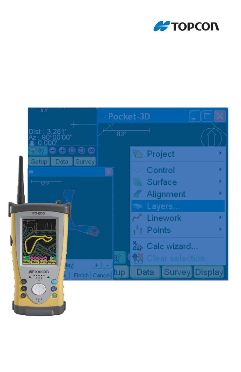
21 Chapter 1 Installing Pocket-3D Welcome to Pocket-3D, the software contractors use to build job files, check cuts and fills, layout points, and survey all or part of a jobsite. This software comes on a CD and is ready to install on a hand-held controller such as, a Topcon FC-200 (Figure 1-1), a TDS Recon, or an hp ipaq and is only available as part of the 3DMC Bundle from Topcon dealers. Figure 1-1. Pocket-3D on Controller (Topcon s FC-200) P/N

22 Installing Pocket-3D Guide to Installing Pocket-3D Pocket-3D installs on any hand-held controller that runs the Windows Pocket PC operating system, including Topcon s FC-200. Pocket-3D initially loads onto your computer, then uses Microsoft ActiveSync to synchronize with the controller and install Pocket- 3D onto the controller. ActiveSync is available for free from the Microsoft website ( and must be installed on the computer before installing Pocket-3D. The Pocket-3D program for your hand-held controller is located on the 3DMC CD. It will first be loaded onto your computer, then ActiveSync will install it onto your controller. 1. Connect your computer and hand-held controller. Because ActiveSync will automatically install Pocket-3D once it has been loaded onto the computer, this step is can be performed at any time. 2. Insert the 3DMC software CD into the computer CD drive of the computer. Navigate to the CD s files using Explorer and open the Pocket-3D folder. 3. Click the Pocket-3D setup icon to run the install program and click Next on the Welcome screen (Figure 1-2). Figure 1-2. Begin Pocket-3D Installation 1-2 Pocket-3D Reference Guide
.")

23 Guide to Installing Pocket-3D 4. Review the License Agreement. If you accept the terms, click the I accept... radio button, then click Next (Figure 1-3). Clicking I do not accept... will terminate the installation. Figure 1-3. Review and Accept License Agreement 5. Click Install to load Pocket-3D on the computer (Figure 1-4). Figure 1-4. Install Pocket-3D on Computer P/N


. Figure 1-5.")
24 Installing Pocket-3D 6. With the computer and controller connected, ActiveSync will start up and retrieve the controller s programs. If Pocket-3D is already installed, ActiveSync ask to uninstall it from the controller. When ActiveSync completes the uninstall process, double-click the Pocket-3D setup icon to have ActiveSync install the software on the controller. 7. ActiveSync will begin the Pocket-3D install process for the handheld controller (Figure 1-5). Figure 1-5. Install Pocket-3D on Controller 8. Click Yes to install Pocket-3D to the default directory on the controller (Figure 1-6). Figure 1-6. Installing into Default Directory 1-4 Pocket-3D Reference Guide
. Figure 1-7.")
25 Guide to Installing Pocket-3D When the controller install completes, ActiveSync displays a notice to check the controller for any further installation procedures. However, Pocket-3D has no further installation steps. Click OK to continue. 9. Click Finish to exit the install program (Figure 1-7). Figure 1-7. Finish Install and Exit P/N
.")

26 Installing Pocket-3D Starting Pocket-3D To start Pocket-3D, press thewindows icon and press Pocket3D in the program list. Upon initial startup, Pocket-3D requires authorization codes to properly run (Figure 1-8). The password protection mechanism has been changed to allow a larger number of options and to provide better security. Because the codes are much longer now, you can import directly from an option file on a USB dongle, etc. Existing installs of Pocket-3D will automatically be upgraded to the new protection mechanism. New users will require codes generated via the new Keygen2 application. Device identification Company name Contact name Company address Contact phone number Contact address Software Type (Pocket-3D) When you receive the authorization codes, enter them into the appropriate fields on the Device Identification screen and press Ok (Figure 1-8). Figure 1-8. Enter Authorization Codes Once entered, the authorization codes can then be located on the about Pocket-3D screen for easy access. To view updated installed options, see Main Screen on page Pocket-3D Reference Guide

27 Main Screen TIP Authorization Codes: More options are now available to provide better security. Because new codes are much longer, you can now import them directly from an option file onto a USB dongle, etc. NOTE Existing installs of Pocket-3D will automatically be upgraded to the new password protection mechanism. Main Screen The Pocket-3D main window (Figure 1-9) has the following components: Main Window displays a graphical representation of the design surface and machine. The display varies according to the selected file and display options. Toolbar provides icons for frequently used functions. See Toolbar on page 1-11 for more information. Menu bar contains pop-up menus for the various functions available in Pocket-3D. The following chapters describe each menu in detail. Figure 1-9. Pocket-3D Main Screen P/N
28 Installing Pocket-3D The pop-up menus on the main screen (Figure 1-15 on page 1-11) contain frequently accessed functions, and information about selected data. To display the pop-up menu, rest the controller s stylus on the point, station, or polyline for at least one (1) second or alternatively press the ALT button. The pop-up (context) menu options depend on the type of file open and the information selected. Clear selection deselects the selected entities (functions the same as the Data Clear selection menu option). Alignment (Figure 1-12 on page 1-10): Stakeout: stakes out the selected point Use as reference line: uses the selected alignment as a reference line during a stakeout Segment Select entire polyline Linework (Figure 1-13 on page 1-10): Add linework: adds the selected linework Edit linework: edits the selected linework Add point to polyline: adds a point to the selected polyline Offset: applies a user-defined horizontal/vertical offset to the selected linework. Delete: deletes the selected linework or the last segment. Stakeout polyline: stakes out the selected polyline Close polyline: closes the selected polyline(s). Use as reference line: uses the selected polyline as a reference line during a stake-out (Figure 1-10 on page 1-9). Reverse polyline(s): reverses the direction of a selected polyline. 1-8 Pocket-3D Reference Guide
 (Figure 1-14 on page 1-10) Add a point: adds the selected point(s). Edit a point: edits the selected point(s).")
 Sta: displays the identifier of the station closest to the point where the stylus was tapped.")
29 Main Screen Figure Lengths Context Menu Option Length: total length of selected polyline. Points adds, edits, deletes, or stakes-out point(s) (Figure 1-14 on page 1-10) Add a point: adds the selected point(s). Edit a point: edits the selected point(s). Delete a point: deletes the selected point(s). Stake-out point: stakes out the selected point(s). Calcs performs common polyline calculations (Figure 1-15 on page 1-11) Sta: displays the identifier of the station closest to the point where the stylus was tapped. Length: shows you the length of the selected polyline and single or multiple polyline segments. Figure Calcs Context Menu Option Move here move the selected entity with the mouse. Properties displays the properties dialog box for the selected entity. Delete points deletes the selected point(s). P/N
 Menu Options Figure 1-12 through Figure 1-15 on page 1-11 shows the context menu")

30 Installing Pocket-3D Properties displays the properties dialog box for the selected entity. Context (Pop-Up) Menu Options Figure 1-12 through Figure 1-15 on page 1-11 shows the context menu options for Alignment, Linework, Point, and Calcs parameters. Figure Context Menu Alignment Options Figure Context Menu Linework Options Figure Context Menu Points Options 1-10 Pocket-3D Reference Guide

31 Toolbar Figure Context Menu Calcs Options Toolbar The toolbar (Figure 1-16) contains icons for frequently used functions. Figure Pocket-3D Toolbar GPS Example Table 1-1 lists and describes the available icons. Table 1-1. Pocket-3D Toolbar Icons Icon GPS Status mmgps Status Total Station Status Robotic Status Description GPS, LPS, mmgps, total station status displays symbols for the type of control application used on the jobsite, as well as the connection status (red for unconnected, green for connected, and orange for low precisions in GPS applications). In GPS control applications, press this icon to display GPS information. See GPS Status Information on page 1-16 for details. In mmgps control applications, press this icon to display GPS information. See GPS Status Information on page 1-16 for details. In total station applications, press this icon to display total station information. See Total Station Status on page 1-20 for details. In robotic applications, press this icon to display robotic information. See Robotic Survey Applications on page 4-64 for details. P/N
32 Installing Pocket-3D Table 1-1. Pocket-3D Toolbar Icons (Continued) Icon Description Zoom out decreases the magnification of the design view each time you tap this button. The zooming pivot is the center of the screen. Zoom in increases the magnification of the design view each time you tap this button. The zooming pivot is the center of the screen. Zoom window increases the magnification of a design area when drawing a box around the selected area. Zoom previous displays the previous design view. Zoom extents displays the extent of the design view/area. Info displays information for selected points/polylines and a dialog box to save the information as a text file. Auto-pan Selection window Selection polygon Pan Click to rotate through the four button options: Auto-pan tracks the user s current position in the field and displays the position as a cross symbol in the middle of the screen. Available only in GPS connection. Selection window selects points/polylines on the screen when drawing a box around them. Selection polygon selects point/polylines on the screen when drawing a polygon around them. Pan moves the design view around when pressing down on the screen and dragging Pocket-3D Reference Guide
33 Menu Bar Menu Bar The menu bar provides access to the Pocket-3D configuration, setup, display, and other jobsite functions (Figure 1-17). For details on the menus, see the following: Setup Menu on page 2-1 Data Menu on page 3-1 Survey Menu on page 4-1 Display Menu on page 5-1 Figure Pocket-3D Menu Bar Table 1-2 describes the functions available in each menu. Table 1-2. Pocket-3D Menu Options Setup Menus Total Station mmgps Menu GPS Functions The options available in the Setup menu depend on the equipment file selected. configures equipment and machine setups configures radios, antennas, and base stations in GPS applications configures transmitters and receivers in mmgps applications configures GRT-2000 setup and LS-2000 receivers in LPS applications configures total stations and prisms in total station applications sets the units for the job P/N
 Data Menu Survey Menu Menu GPS mmgps Total Station Functions The options available in the Data menu depend on the equipment file and design surface file selected.")
34 Installing Pocket-3D Table 1-2. Pocket-3D Menu Options (Continued) Data Menu Survey Menu Menu GPS mmgps Total Station Functions The options available in the Data menu depend on the equipment file and design surface file selected. creates, configures, and sets control point files creates, configures, and sets surface files creates, configures and sets linework files creates, configures and provides access to importing or exporting control and point files performs various calculations The options available in the Survey menu depend on the equipment file selected. connects and disconnects the GPS receiver or total station starts and stops tracking the total station in total station applications sets the type of connection for the total station enables and disables the use of a reflectorless total station in total station applications measures points and polylines in the field performs auto-topo operations for topographic surveys (not available for some total station instruments/applications) performs stake-outs 1-14 Pocket-3D Reference Guide
35 Pocket-3D Technical Information Display Menu Table 1-2. Pocket-3D Menu Options (Continued) Menu For context menu options, see Main Screen on page 1-7. Pocket-3D Technical Information Functions The options available in the Display menu depend on the equipment file selected and the types of data active. zooms in, out, or pans around the main screen selects points and/or polylines individually or in bunches shows the scale bar, the direction of travel, and/or the point of reference orients the screen to a desired direction displays, orients, aligns grid lines as desired shows a section view of the design surface (only available for certain surfaces) shows the cut/fill history (available for mmgps applications) shows the grade indicator when an active surface displays. changes the background color selects the language for Pocket-3D on the next start up of program displays the about Pocket-3D dialog box To view Pocket-3D information, press Display About Pocket-3D. The about Pocket-3D dialog box displays the version levels for the application program, copyright information, registration, and ID number (Figure 1-18 on page 1-16). See Main Screen on page 1-7 for viewing options. P/N
36 Installing Pocket-3D Figure About Pocket-3D GPS Status Information Once connected to a GPS/mmGPS system, the status button on the toolbar turns green (GPS) or blue (mmgps). Press the status button to view or edit the different application-specific parameters (Figure 1-19 on page 1-17). GPS Status While in GPS control, to view GPS information, change the mask angle or reset the receiver, press the GPS status button on the toolbar. The GPS status dialog box displays (Figure 1-19 on page 1-17). The color of the button and state of the hardware symbol indicates the status of the system. Background color green means the entire system communicates with Pocket-3D; red means all or some part of the system is not communicating with Pocket-3D; orange means low precisions. Hardware symbol state if the symbol is crossed out, the corresponding sensor/receiver is not available. If the radio link is between 3 and 10 seconds old, the radio icon will flash (bad or weak signal); after 10 seconds, it will be crossed out (unavailable signal) Pocket-3D Reference Guide

37 GPS Status Information GPS Status Icon mmgps GPS Status Icon Figure GPS/mmGPS Status Button and Dialog Box Monitor GPS Status Information To monitor the fix status of the GPS+ receiver, press the GPS status button. The Fix tab displays the following information (Figure 1-19): The initialization status of the GPS+ and mmgps system Total sats tracked the total (GPS and GLONASS) number of satellites being tracked GPS sats used and GLONASS sats used the number of GPS and GLONASS satellites being used Horz. RMS and Vert. RMS an estimation of the positioning quality computed from a valid satellite status (RMS = Root Mean Square) View the Receiver s Current Position To view the current position of the GPS+ receiver, press the GPS status button, then tap the Position tab on the GPS status dialog box. The Position tab displays the following information (Figure 1-20 on page 1-18): latitude, longitude, and ellipsoid height of the GPS+ antenna northing, easting, and elevation of the GPS+ antenna the distance from the receiver to the base station P/N
. Satellite plot displays used and unused satellites, and the current mask angle.")

38 Installing Pocket-3D Monitor Satellites and Enter the Mask To monitor the current distribution of satellites or enter the mask angle for satellites, press the GPS status button, then tap the Satellites tab on the GPS status dialog box. The Satellites tab displays the following information (Figure 1-20). Satellite plot displays used and unused satellites, and the current mask angle. Blue dots: GPS satellites Red-with-cross dots: GLONASS satellites Black dots: unused satellites Red mask circle: satellites inside will be used for positioning Mask enters and sets the mask angle for the job. Figure Position and Satellites Tabs View Receiver Information or Reset Receiver To view the receiver s ID number and firmware version, press the GPS status button, then tap the Info tab on the GPS status dialog box. If needed, use the left/right arrows to navigate to the Info tab. The Info tab displays the following (Figure 1-21 on page 1-19): Identification information, firmware revision, and radio link information (type, latency, and quality) for the receiver. Reset receiver press to clear all data and reset all settings stored for the GPS+ receiver Pocket-3D Reference Guide


39 GPS Status Information Reset RTK press to reset RTK ambiguities. View PDOP Values To view PDOP values for planning purposes, press the GPS status button, then tap the Planning tab on the GPS status dialog box. If needed, use the left/right arrows to navigate to the Planning tab. The Planning tab displays PDOP information at an hourly scale and covers a 24-hour period (Figure 1-21). Press Next to display PDOP values for the next day. Press Previous to display PDOP values for past days. Figure Info and Planning Tabs Apply GPS Receiver Settings To apply advanced GPS receiver settings, press the GPS status button, then tap the Advanced tab (Figure 1-22 on page 1-20) on the GPS status dialog box. If needed, use the left/right arrows to navigate to the Advanced tab. The Advanced tab contains the following GPS receiver settings. Use multipath reduction leave enabled to reduce multiple reflections from nearby objects. Use GLONASS satellites leave enabled to include in position calculations and to display on the satellite plot. P/N

40 Installing Pocket-3D Figure Advanced Tab Total Station Status While in total station control, to view total station information, change search area or change track sensitivity and speed, press the Total Station status button on the toolbar (Figure 1-23 on page 1-21). The color of the button and state of the hardware symbol indicates the status of the system. Background color green means the entire system communicates with Pocket-3D; red means all or some part of the system is not communicating with Pocket-3D. Hardware symbol state if the symbol is crossed out, the corresponding sensor/receiver is not available. NOTE For non-robotic total stations, the prism symbol will remain crossed out. The instrument selected during equipment setup determines the tabs that display Pocket-3D Reference Guide


41 GPS Status Information Total Station Status Icon Figure Total Station Status Button and Dialog Box Monitor Prism Position Information To monitor the position status of the prism, press the Total Station status button. The Position tab displays the following information (Figure 1-23): whether or not the prism is connected and tracks the total station horizontal/vertical angles and slope distance to the prism northing, easting, and elevation of the prism Set Total Station Search Parameters To set total station search parameters, press the Total Station status button, then tap the Search tab on the total station status dialog box (Figure 1-24 on page 1-22). Depending on the total station used and the sensor type, enter or select the following information (Figure 1-24 on page 1-22) and press Ok: Search wait (secs) sets the wait time in seconds until the total station starts to search for the prism (robotic total stations only). Pattern selects the pattern for tracking the prism. Search area left and right of prism when enabled, sets the search area at the total station for tracking the prism. P/N

, press the Total Station status button, then tap the Track tab on the total")
42 Installing Pocket-3D Above and below prism enter the angle above and below the prism in which to search. Set Total Station Tracking Sensitivity and Speed To set total station tracking parameters (Figure 1-24), press the Total Station status button, then tap the Track tab on the total station status dialog box. Figure Search Tab for Total Station 1-22 Pocket-3D Reference Guide
 has the following menu items. Some menu items depend on the type of equipment configured (machine or rover).")
43 Chapter 2 Setup Menu Depending on the application (GPS, mmgps, or total station), the Setup menu contains different options for configuring system components. GPS Applications In GPS applications, the Setup menu (Figure 2-1) has the following menu items. Some menu items depend on the type of equipment configured (machine or rover). Equipment Radios Antenna Base Station mmgps transmitters (mmgps application) mmgps receiver (mmgps application) Units Figure 2-1. Setup Menu for GPS Applications P/N
44 Setup Menu Equipment The Equipment menu creates and edits equipment configuration files. Equipment configuration files contain information specific to the equipment; such as, machine type, receiver type and location, dimensions of the cutting edge, offset lengths depending on the position of the receiver, and radio configuration. NOTICE Equipment setup is used for Rover setups, not Base station setups. To access available equipment configuration files, tap Setup Equipment (Figure 2-2). Figure 2-2. Setup Equipment From the Equipment configurations dialog box (Figure 2-3 on page 2-3), equipment configuration files can be created within Pocket-3D and transferred to the machine Control Box to be used for machine configuration. (A machine configuration file must be created before grading.) Refer to the System Five-3D Reference Manual for more information on the Control Box. 2-2 Pocket-3D Reference Guide

45 GPS Applications Figure 2-3. Equipment Configurations Dialog Box Once equipment configuration files are created and stored in the internal memory, they can be selected and adjusted at the beginning of the job, depending on the receiver s setup. On the Equipment configurations dialog box, press New to display the Configuration name/type dialog box (Figure 2-4 on page 2-4) and create an Equipment Configuration file. Enter the following information and press Next. Some selections depend on purchased options for Pocket-3D. Configuration name type a name for the Equipment Configuration. Machine type select Range pole, Bulldozer, or Motor grader. The screens display different settings depending on the machine type selection. Sensor select the type of sensor used on the machine; either GPS antenna or Prism, or LS-2000 for 3-track curb & gutter. Location select the sensor s location; Top of pole for Range pole, Middle for Bulldozer, or Left/Right for Motor grader. Units select the unit of measure. Note: these units do not relate to job units. P/N
: Antenna type select the type of antenna.")
46 Setup Menu Figure 2-4. Configuration Name/Type On the antenna information dialog box, enter the following information using the same units of measure entered in the previous step and press Next. These settings have a corresponding Image tab to illustrate the setup. For range poles, enter the following antenna information (Figure 2-5): Antenna type select the type of antenna. Antenna height enter the antenna height of the GPS+ antenna from antenna measurement point to pole tip. Measured to enter where on the GPS+ antenna the antenna height was measured. Connection (Pocket-3D) select the communication port used between controller and instrument. Figure 2-5. Range Pole Antenna Setup Information 2-4 Pocket-3D Reference Guide
47 GPS Applications On the radio setup dialog box (Figure 2-6 on page 2-5), set the following parameters and press Next: Radio type the type of radio. Connected the port used for radio connection. Baud rate the speed of communication rate between the radio unit and the GPS+ receiver. Format current GPS+ systems are capable of either CMR or RTCM corrections. Figure 2-6. Radio Setup On the Machine configuration complete dialog box (Figure 2-7), press Finish to save the configuration file. Figure 2-7. Machine Configuration Complete Dialog Box P/N
48 Setup Menu Radios To configure radio settings, tap Setup Radios (Figure 2-8). Figure 2-8. Setup Radio On the radio setup dialog box, set the following parameters and press Ok (Figure 2-9 on page 2-7): Radio type the type of radio. Port the port used for radio connection. Baud rate the speed of communication rate between the radio unit and the GPS+ receiver. Format current GPS+ systems are capable of either CMR or RTCM corrections. Configure changes the radio channel. Press Configure to display the channel configuration dialog box (Figure 2-9). 2-6 Pocket-3D Reference Guide
49 GPS Applications Select the desired channel and the corresponding Frequency displays. Press Set to apply the radio channel parameters. Figure 2-9. Radio Setup and Channel Configuration Dialog Boxes Antenna To edit/view antenna measurements, tap Setup Antenna (Figure 2-10). Figure Setup Antenna On the antenna setup dialog box, set the following parameters and press Ok (Figure 2-11 on page 2-8): Antenna type select the type of antenna. Antenna height enter the antenna height of the GPS+ antenna. Measured to enter where on the GPS+ antenna the antenna height was measured. P/N
.")
, set the following parameters and press Next:")
50 Setup Menu Units select the unit of measure. Base Station Figure Antenna Setup To set Base Station information, tap Setup Base Station (Figure 2-12). NOTE If the Base station menu item is unavailable, disconnect from the GPS receiver (Survey Disconnect from GPS). Figure Setup Base Station On the base station configuration dialog box (Figure 2-13 on page 2-9), set the following parameters and press Next: Control point select the appropriate control point for the base position from the control point drop-down list. 2-8 Pocket-3D Reference Guide
, set the following parameters and press Ok: Antenna")

51 GPS Applications Connection (Pocket-3D) select the connection to the receiver. Figure Base Station Configuration On the antenna setup dialog box (Figure 2-14), set the following parameters and press Ok: Antenna type select the type of antenna. Antenna height enter the antenna height of the GPS+ antenna. Measured to enter where on the GPS+ antenna the antenna height was measured. Units select either meters, feet, inches, or centimeters. Figure Antenna Setup Base Station P/N

52 Setup Menu On the radio setup dialog box, set the following parameters (Figure 2-15): Radio type the type of radio. Port the port used for radio connection. Baud rate the speed of communication rate between the radio unit and the GPS+ receiver. Format current GPS+ systems are capable of either CMR or RTCM corrections. Configure changes the radio channel. Press Configure to display the channel configuration dialog box (Figure 2-15). Select the desired channel and the corresponding Frequency displays. Press Set to apply the radio channel parameters. Press Next to display the GPS receiver settings dialog box. Figure Radio Setup and Channel Configuration Dialog Boxes On the GPS receiver settings dialog box (Figure 2-16 on page 2-11) do the following and press Finish to connect to the GPS receiver. Use co-op tracking if enabled, allows higher efficiency of multipath reduction. This option is only valid for a base station receiver (non-moving). Use multipath reduction if enabled, reduces multiple reflections from nearby objects. Use GLONASS satellites if enabled, these satellites will not be included in the position calculations and will not display on the satellite plot if disabled Pocket-3D Reference Guide
, select the desired units for each item from the drop-down lists.")

53 GPS Applications Figure Select GPS Receiver Settings Units To set project units, tap Setup Units (Figure 2-17). Figure Setup Units On the units dialog box (Figure 2-18 on page 2-12), select the desired units for each item from the drop-down lists. Press Ok to continue; Pocket-3D saves the entered units. The units can be changed at any time; Pocket-3D automatically saves the changes. Distances select either Meters, US Survey feet, International feet, or Feet + Inches. If using Feet+Inches, all values will show as 1'11''1/2 where 12 inches equal 1 foot and any value smaller than an inch will show as a fraction of an inch. P/N

54 Setup Menu Decimal Places select either 0, 1, 2, 3, or 4 decimal places. Angles select either DD MM SS, NDD MM SS E, Gons, or DD.DDDD. Areas select either Square meters, Square feet, Acres, or Hectares. Volumes select either Cubic meters or Cubic yards. Coords select either North-East-Elev, East-North-Elev, X-Y-Z, or X-Y-Z South Azimuth. Stations select either , , , or Grades select either Percent (%), Run : Rise, or Rise : Run. Exit Figure Units Parameters To exit Pocket-3D, tap the icon in the upper-right corner of the screen. The Confirmation dialog box displays (Figure 2-19 on page 2-13). Press Yes to exit the program or press No to return to the main screen Pocket-3D Reference Guide
55 Equipment Configuration Files Figure Pocket-3D Exit Confirmation Dialog Box Equipment Configuration Files Equipment configuration files contain information on the specific machine, GPS+ receiver, prism, radio, etc., for the job application and setup. Pocket-3D uses this information to accurately portray jobsite information on the main screen. The following sections provide example equipment configurations: one for a range-pole with a HiPer Lite receiver, one for a motor grader machine rover with mmgps, one for a motor grader with an LS-2000 receiver, and another one for a prism/total station setup. An equipment configuration file can be created in one of two ways: Import the file created at the System Five-3D Control Box through the compact flash card using the Copy button. See Project on page 3-2 for details. Create the file manually. P/N
56 Setup Menu Sample Configuration 1: Range-pole with HiPer Lite Receiver Before initializing or localizing a GPS+ system, there must be an equipment configuration file defined in Pocket-3D. The following procedure is an example of a HiPer Lite receiver configuration. NOTICE Incorrect measurements or typographical errors will have a direct affect on grading accuracy. 1. Press Setup Equipment. The Machine files dialog box displays. 2. On the Machine files dialog box, press New to create (or Edit to change a selected file) an equipment configuration (Figure 2-20 on page 2-15). 3. On the Configuration name dialog box, set the following equipment parameters, and press Next (Figure 2-20 on page 2-15): Configuration name enter a name for the Equipment Configuration file on the alphanumeric pop-up keyboard. Machine type select Range pole from the drop-down list. Sensor select GPS Antenna from the drop-down list. Mounting location select Top of pole from the drop-down list Pocket-3D Reference Guide
.")
 select the appropriate connection. Figure 2-21.")
57 Equipment Configuration Files Units select the type of unit measurement from the drop-down list. Figure Equipment Configuration Dialog Box 4. Enter the following information using the same units of measurement entered in the previous step, then press Next to continue (Figure 2-21). These settings have a corresponding Image tab to illustrate the setup. Antenna type select Topcon HiPer Lite. Antenna height enter the antenna s measured height Measured to select either Base or Rim. Connection (Pocket-3D) select the appropriate connection. Figure Antenna Information Dimensions/Image Tab 5. Set the following radio parameters, and press Next to continue (Figure 2-22): P/N

58 Setup Menu Radio type for a HiPer Lite, the default is selected; otherwise, select the radio type for the receiver. Connected to select serial port (usually Port C) from the drop-down list. Baud rate select from the drop-down list. Format select CMR from the drop-down list. 6. Press Finish to save the configuration file. Pressing Cancel will cause the configuration s information to be lost (Figure 2-22). Figure Radio Setup Dialog Box 7. On the Equipment configuration dialog box, select the new or edited configuration file, and press Ok to continue (Figure 2-23 on page 2-16). 8. At the verification screen, press Yes to apply the configuration as the current equipment (Figure 2-23). Figure Select Equipment Configuration 2-16 Pocket-3D Reference Guide
59 mmgps Applications mmgps Applications In mmgps applications, the Setup menu (Figure 2-24) has the following additional menu items. Except for mmgps setup options, the Setup menu for mmgps applications is the same as for GPS applications. Other differences are noted below. mmgps transmitters mmgps receiver mmgps Icon Equipment Figure Setup Menu for mmgps Applications For further details on the Equipment menu option and setup screens, see on page During rover equipment setup for mmgps applications, an additional screen configures GPS connections; machine setups for mmgps stay the same. mmgps Transmitters Transmitter calibration data must first be downloaded into Pocket-3D using the Transmitters tab (Figure 2-26 on page 2-19). Once this tab contains a list of transmitters, up to four transmitters can be set up on unique channels using the channel tabs (see below). The channel button on the transmitter determines the channel that the transmitter broadcasts on. P/N
: To select a Serial Cable select the communication port used between the controller and transmitter;")
60 Setup Menu To set up transmitter information, tap Setup mmgps transmitters (Figure 2-25). Figure Setup mmgps Transmitters The Transmitters tab performs the following (Figure 2-26 on page 2-19): To select a Serial Cable select the communication port used between the controller and transmitter; either COM or Bluetooth comport. To add a transmitter tap Add and enter a transmitter serial number or other description. To delete a transmitter select a transmitter and tap Delete. To calibrate the transmitter see TX Calibration on page To load transmitter data for the first time tap Download to retrieve calibration data from the connected transmitter. The 2-18 Pocket-3D Reference Guide
61 mmgps Applications download is complete when the firmware version displays in the Firmware column. Figure View Transmitters Loaded into Pocket-3D The Channel tab displays the following transmitter information (Figure 2-27): Channel the channel the transmitter is using. Transmitter the ID of the transmitter. ControlPt. the control point over which the transmitter is set up. Height the height of the transmitter. Edit Channel see Edit Channel on page Figure Enter Transmitter Channel Information P/N
 away.")

62 Setup Menu TX Calibration The transmitter calibration (adjustment) function fixes errors in incline in the self-leveling mechanism of the transmitter, applying an offset to the transmitter. The transmitter must be in calibration mode for this function and the Rover setup approximately 30 meters (100 feet) away. The height of the sensor must be at an angle less than 1 in relation to the transmitter. NOTICE If the sensor experiences excessive movement during any stage of the adjustment, an error message will display. Press Cancel and stabilize the Rover pole. Then press TX calibration again. To begin a resection, tap TX Calibration on the Transmitters tab of the transmitter setup dialog box. If needed, check the setup listed on-screen (Figure 2-28) and tap OK. Figure Begin TX Calibration Adjustment 2-20 Pocket-3D Reference Guide
.")
63 mmgps Applications On the transmitter adjustment process dialog boxes (Figure 2-29), follow the instructions on each screen. Press Next to continue. Figure Transmitter Adjustment Process When the adjustment completes, the Adjustment dialog box displays the offsets (Figure 2-30 on page 2-22). If both Axis measurements are less than 10'', no adjustment is needed at the transmitter. If either or both Axis measurements are more than 10'', disconnect from the sensor and connect to the transmitter. Press Finish to upload the adjustments to the transmitter. When finished uploading, the transmitter will apply the adjustments and turn off. TIP After loading the new self-leveling offset data into the transmitter, re-calibrate to check the system. The transmitter may need to be calibrated a couple of times depending on site conditions. P/N
.")
64 Setup Menu Figure Adjustment Results NOTE This process only applies an offset to the selfleveling mechanism to ensure correct grade. The control point file is not affected. Edit Channel To edit information for the selected transmitter, tap the Edit Channel button on the Channel tab (Figure 2-31 on page 2-23). On the edit channel dialog box, edit and select the following parameters and press Ok to save (Figure 2-31 on page 2-23). 1. Transmitter select the desired transmitter from the drop-down list. 2. Control point select the control point for the transmitter s position from the drop-down list. 3. TX height enter the height of the transmitter. 4. Measured to select where on the transmitter (Base or Mark/ Slant) the height was measured. 5. Benchmark check see Benchmark Check on page Pocket-3D Reference Guide
 or a point of known elevation.")
65 mmgps Applications 6. Resection see Resection on page Benchmark Check Figure Edit Channel This function determines the height of the mmgps transmitter over a known control point (benchmark) or a point of known elevation. To take a height measurement of the transmitter, tap Benchmark check on the channel setup dialog box after entering transmitter information (Figure 2-32). Figure Begin Height Check On the transmitter height dialog box, select one of the following and press OK to measure (Figure 2-33 on page 2-24). During the measurement, the Measuring dialog box displays. P/N

66 Setup Menu 1. If the transmitter is set up over a known control point, tap the first radio button, then select the control point from the drop-down list. 2. If the transmitter is set up over a point with a known elevation tap the second radio button, then enter the elevation of the Rover receiver. When done, the Transmitter height fields display the vertical difference between the height originally specified for the transmitter and the calculated height (Figure 2-33). 3. Press OK to apply the measured height to the transmitter setup. 4. Press Cancel to exit without saving the measurement. Figure Measure Height of Transmitter Resection The resection function measures an unknown transmitter location using the rover and three or more points. In general, the results from a resection are adequate for horizontal positioning of the transmitter (an error estimate will also display). Performing a height check and adjustment will fine-tune the calculated elevation. When performing a resection, use the following guidelines to ensure accurate measurements at the Rover points: take measurements at three or more points around the Base transmitter in a balanced, symmetrical pattern (not clustered in one area) 2-24 Pocket-3D Reference Guide
. Figure 2-34.")
67 mmgps Applications have the sensor facing towards the transmitter during each measurement angle the sensor between 6 higher or lower than the transmitter s beam, not straight on To begin a resection, tap the Resection button on the channel setup dialog box (Figure 2-34). Figure Begin Resection On the resection dialog box, enter the following parameters and press Measure (Figure 2-35 on page 2-26). During the measurement, the Measuring dialog box displays. When done, the Pts. in calculation field will increment by one. Duration (secs) enter the duration, in seconds, in which to measure the point. H. Precision / V. Precision enter a horizontal / vertical precision, in the project s units, with which to measure the point. After three points have been successfully measured, horizontal and vertical errors for the measured point will display (Figure 2-35 on page 2-26). Further measurements should improve the positional error. To clear the measurements and begin again, press Reset. The point name will be automatically added to the list of control points as TX-[n] (Resected), where n is the channel number. Subsequent resections with the same transmitter will overwrite any previous points. P/N
: GPS port")

68 Setup Menu mmgps Receiver Figure Resection To set mmgps receiver information, tap Setup mmgps receiver (Figure 2-36). Figure Select mmgps Receiver Parameters On the mmgps setup dialog box, set the following parameters and press Ok (Figure 2-37 on page 2-27): GPS port select the port used for communication between receiver and sensor (typically port D). Sensitivity select Auto to automatically control the mmgps receiver s detection level of the transmitter s signal. Select a different setting when working at very short or very long 2-26 Pocket-3D Reference Guide

69 mmgps Applications distances, or during inclement weather that can affect laser detection. Channels select the channel to scan for mmgps connection. Firmware the firmware version displays after the download of calibration data from the connected transmitter completes. Advanced select advanced mmgps options. mmgps aided initialization: select to use the mmgps signal to assist in initializing the GPS receiver. Calc weighted mmgps/gps elevation: select to combine mmgps elevations and GPS elevations. Figure Select mmgps Receiver Information P/N
70 Setup Menu Total Station Applications In total station applications, the Setup menu has a Range-pole menu item (Figure 2-38). Total Station Icon Equipment Figure Setup Menu for Total Station Applications For further details on the Equipment menu option and setup screens, see Equipment on page For the range pole and total station, enter and select the following information during equipment configuration (Figure 2-39 on page 2-29), then press Next: Instrument select the desired total station (GPT8000). 1. Vert. prism height enter the vertical height of the prism. Prism constant enter the prism constant. This constant is dependent on the manufacturer of the prism; usually 30 mm for a single prism and zero for a 360 prism. Connection (Pocket-3D) select the communication port used between the controller and instrument; COM1 Serial Port, COM 2 Serial 1, or Bluetooth on equipped total stations Pocket-3D Reference Guide
71 Total Station Applications Figure Setup/Image Tabs for Total Station On the Advanced dialog box for prism sensors only, select how you want to connect the total station (Figure 2-40 on page 2-30), then press Next. Cable in STD mode select to connect the total station via standard cable. Cable in Ext. Link mode select to connect the total station via cable Radio Modem (Ext. Link) select to connect total station via Radio Modem. RC (Ext. Link) select to connect total station via remote control. NOTE For a conventional total station, for example GTS 200, you can only connect via Cable in Standard Mode. P/N
72 Setup Menu Figure Select Total Station Connection Type A confirmation box displays to save the machine configuration file. Press Finish (Figure 2-41). Range-pole Figure Save the Configuration To set up the range pole, tap Setup Range-pole (Figure 2-42 on page 2-31). On the range pole setup dialog box (Figure 2-42 on page 2-31), select or enter the following parameters and press Ok. Units select the unit of measure. Note: These units do not relate to job units Pocket-3D Reference Guide

73 Total Station Applications Vert. dist. from prism center to pole tip enter the measured distances for the prism and the offset. Height of prism: enter the vertical height of the prism. Prism offset: enter the prism offset. Figure Range Pole Parameters Sample Configuration 3: Prism and Total Station Before beginning to track a prism, there must be an equipment configuration file defined in Pocket-3D. The following procedure is an example of a prism configuration for a GPT-8000 series total station. 1. Press Setup Equipment to create or select an equipment configuration file. The following steps describe creating a file. 2. On the Machine files dialog box, press New to create (or Edit to change) a total station configuration (Figure 2-43 on page 2-32). 3. On the Configuration name dialog box, set the following equipment parameters, and press Next (Figure 2-43 on page 2-32). Configuration name enter a name for the configuration file. Machine type select Range pole from the drop-down list. Sensor select prism from the drop-down list. Location select Top of pole from the drop-down list. P/N
.")

74 Setup Menu Units select the type of unit measurement from the drop-down list. Figure Equipment Configuration File for Total Station 4. Enter the sensor information using the same units of measure entered in the previous step, then press Next to continue (Figure 2-44 on page 2-33). These settings have a corresponding Image tab to illustrate the setup. Instrument select the desired total station from the drop-down list. Vert. prism height enter the vertical height of the prism. Prism constant enter the prism constant. This constant is dependent on the manufacturer of the prism; usually -30 mm for a single prism and zero for a 360 prism. Connection (Pocket-3D) select the communication port used between the controller and instrument; COM1 or Bluetooth on equipped total stations Pocket-3D Reference Guide

. 8.")
75 Total Station Applications Figure Sensor Information Dialog Box 5. On the Advanced dialog box, select the connection type, Baud rate, Data Bits, Stop Bits, and Parity used for communication with the total station and press Next to continue (Figure 2-45). 6. Press Finish to save the configuration file (Figure 2-45). Pressing Cancel will cause the configuration s information to be lost. Figure Select Advanced Parameters 7. On the Equipment configuration dialog box, select the new or edited configuration file, and press Ok to continue (Figure 2-46 on page 2-34). 8. At the verification screen, press Yes to apply the configuration to be the current equipment (Figure 2-46 on page 2-34). P/N


76 Setup Menu Figure Select Equipment Configuration Robotic Applications The Setup menu for robotic applications is the same as for range pole applications (Figure 2-47). The differences are noted below. Figure Setup Menu for Total Station Applications Equipment To use the radio to communicate to the controller, do the following: Click Setup Equipment New. The Configuration dialog box displays (Figure 2-48 on page 2-35) Pocket-3D Reference Guide
 (or GTS900 [Figure 2-49 on page 2-36]) and connect via Radio Modem (COM3)((Figure 2-48) or")
77 Equipment For the range pole and robot application, enter a name for the robotic application, select Range pole as machine type, and a Prism as the sensor. Select GTS900MC as the communication port used between the controller and the instrument (Figure 2-48) (or GTS900 [Figure 2-49 on page 2-36]) and connect via Radio Modem (COM3)((Figure 2-48) or RC3/BT COM6 (Figure 2-49 on page 2-36). Press Next. The Setup/Image dialog box displays (Figure 2-48 on page 2-35). Press Next again (the Advanced dialog box displays) to connect via the Radio Modem (Figure 2-48 on page 2-35) or the RC3 (Figure 2-49 on page 2-36). Figure Using Radios (COM3) as Communication P/N
 as the Communication Device Station Setup To set the occupy and backsight stations of the instrument, tap Setup Station Setup (Figure 2-50).")
78 Setup Menu The type of communication selected determines the equipment setup configuration. Figure Using RC3 (BT COM6) as the Communication Device Station Setup To set the occupy and backsight stations of the instrument, tap Setup Station Setup (Figure 2-50). Figure Setup Station Setup 2-36 Pocket-3D Reference Guide
79 Station Setup On the setup method dialog box, set the parameters for the four station setup methods: Known station & BS pt, Known station & azimuth, New station by Resection, and Unknown pts, then press Next. Known station & BS pts: the most common method. Select a station point and a backsight point from the list of control points for the job site. 1. On the Setup method dialog box (Figure 2-51 on page 2-38), set the following parameters: Instrument height enter the measured height of the instrument. Units enter the units used to measure the height of the instrument, then press Next. The backsight setup dialog box (Figure 2-51 on page 2-38) displays. 2. On the backsight setup dialog box, select or enter the following parameters: Filter List select either Control points or Point from the drop-down list. Layer if Point is selected, select a layer from the drop-down list. Station select the control point over which the instrument is set. Backsight select the control point used as the backsight. Backsight has prism check mark this box if the backsight has a prism. Target height: enter the height of the backsight prism. Prism constant: enter the prism constant for the backsight prism. P/N

80 Setup Menu Setup Method Dialog Backsight Setup Dialog Box Figure Known Station & BS Points Setup Method Known station & azimuth select a station point from the list of control points and enter an azimuth value for the orientation. 1. On the Setup method dialog box, enter instrument height and unit of measurement as described above (page 2-37). The backsight setup dialog box displays. 2. On the backsight setup dialog box (Figure 2-53 on page 2-39), select or enter the following parameters: Filter List select either Control points or Point from the drop-down list. Layer select a layer from the drop-down list, if Point was selected from the Filter List. Backsight azimuth enter the desired azimuth for the backsight Pocket-3D Reference Guide

81 Station Setup Figure Sight/Backsight Dialog Box 3. Press Next to display the sight backsight dialog box (Figure 2-52 on page 2-39). 4. Press Ok to continue. Setup method dialog box Backsight Setup Dialog Box Figure Known Station and Azimuth Setup Method New station by resection add a control point to the resection and take a measurement to each point. 1. On the Setup method dialog box (Figure 2-54 on page 2-40), enter instrument height and unit of measurement as described above, (page 2-37) then press Next. The control points dialog box displays (Figure 2-54 on page 2-40). 2. On the control points dialog box, do the following: P/N

82 Setup Menu Add press to add point/control points to the resection. The Backsight results dialog box (Figure 2-55 on page 2-41) displays. Edit press to edit a highlighted point/control point, then press Ok to return to the control points dialog box. Setup Method dialog box Control Points dialog Figure New Station by Resection Setup Method Delete press to delete a highlighted point/control point on the control points dialog box, then press Ok. Press Yes to confirm or No to cancel. NOTE You can use any number of points, but at least 3 points should be used for an accurate resection. Once computed, add the new, resected point to the control point file. On the Backsight results dialog box (Figure 2-55 on page 2-41), select or enter the following parameters: Filter List select either Control points or Point from the dropdown list. Layer select a layer file from the drop-down list, if Points was selected from the Filter List. Name select the control point to be used in the resection from the drop-down list Pocket-3D Reference Guide

, enter instrument height and unit of measurement as described above, (page 2-37) then press Next.")
83 Station Setup Usage select either H. Angle only, H.&V. Angles, H.,V. Angles & SD., or Disabled to specify how the control point will be used. HT enter the height of the control point s prism. H.Angle enter the horizontal angle difference. V.Angle enter the vertical angle difference. S.Dist enter the slope distance difference. Observe press to measure the control point. Control Points dialog Backsight Results dialog Figure Backsight Results Unknown point automatically create this point in the database as point On the Setup method dialog box (Figure 2-54 on page 2-40), enter instrument height and unit of measurement as described above, (page 2-37) then press Next. The Station coordinates dialog box displays (Figure 2-56 on page 2-42). 2. The Station coordinates dialog box (Figure 2-56 on page 2-42) verifies the North(ing), East(ing), and Elev(ation) for the new control point. P/N
.")
, sights the backsight. 4.")
84 Setup Menu Figure Station Coordinates Dialog Box 3. Press Finish to continue (Figure 2-56). The sight backsight dialog box displays. The sight backsight dialog box (Figure 2-57), sights the backsight. 4. Press Ok to continue. Figure Sight Backsight 2-42 Pocket-3D Reference Guide
85 Chapter 3 Data Menu The Data menu (Figure 3-1) has the following menu items: Project Control Surface Alignment Layers Linework Points Calculation type Clear Selection Figure 3-1. Data Menu Options P/N

.")
86 Data Menu Project In GPS control applications, the project engineer provides a design surface file for the jobsite. The correct file must be copied into the GX-60 control box and selected as the project for the jobsite. To access available Project files or to create a new Project file, tap Data Menu Project <none> (Figure 3-2). Figure 3-2. Data Project Menu [File To change the Project file, highlight a file from the list and press Ok (Figure 3-3 on page 3-2). At the verification screen, press Yes to use this Project file for the current project. Project files can be created, copies, or deleted. GPS localization files can also be viewed and saved. Figure 3-3. Copy a Project File 3-2 Pocket-3D Reference Guide
.")
87 Project New create a new file by entering a filename. After naming the file, press Ok to save the information (Figure 3-4). Figure 3-4. New Project File Info displays the information on the selected file (Figure 3-5 on page 3-3). Press Save to save the information as a text file on the Save as dialog box or Cancel to return to the previous screen. Enter the name of the new file and press Ok. Figure 3-5. Project File Information Copy copies a file either from internal memory, Network or CF (Compact Flash) Card, to the Network or CF card. The touch P/N

88 Data Menu screen lists all file available for copying. Select a file to copy, then press Ok. At the verification screen, press Ok again. Figure 3-6. Copy Project Files Delete removes an existing file from internal memory. Select a file to remove, then press Delete. The program always reminds the operator to confirm deletion of a selected file. Select Yes to confirm the deletion. Rename opens the New project file name dialog box (Figure 3-4 on page 3-3) to change the name of the selected file. Save As opens the New project file name dialog box (Figure 3-4 on page 3-3) to save the selected file under a new name. Import/Export To import a project file, tap Topcon Logo Data Project Import/Export From TP3 file on the Main Screen (Figure 3-7 on page 3-5). 3-4 Pocket-3D Reference Guide
. Figure 3-8.")
89 Project Figure 3-7. Select a Design Surface File 1. On the File dialog box, select a project (.TP3) file to import. Then click Open. The Copy files dialog box displays (Figure 3-8). Figure 3-8. Import a Project File P/N
90 Data Menu 2. On the Surface(s) dialog box (Figure 3-9), select the surface to import from the list. Then press Next. Figure 3-9. Select a Surface File to Import 3. On the Linework(s) dialog box (Figure 3-10), select one of the following, then press Next: None enable to display no polylines. All polylines enable to display all polylines in the project. Selected polylines only available only if polylines are highlighted (selected) on the main screen. Polylines by layer enable to select a layer to import from the drop-down list. Figure Select Lineworks for the Project 3-6 Pocket-3D Reference Guide
91 Project 4. On the Point(s) dialog box (Figure 3-11), do the following to import points, then press Next: None enable to display no points. All points enable to display all points in the project. Selected points only available only if points are highlighted (selected) on the main screen. Points by layer enable to select a layer to import from the drop-down list. Figure Select Points to Import for the Project 5. On the Control data dialog box (Figure 3-12 on page 3-8), do the following to import control point data, then press Next: Control point(s) check mark this box to import control points. Localization check mark this box to import localization data. MMGPS Transmitter(s) check mark this box, when available, to import MMGPS transmitter data. P/N
, press Finish to save and display the results on the main screen or press Back to edit your selections.")
92 Data Menu Figure Control Data for the Design Surface 6. On the Import dialog box (Figure 3-13), press Finish to save and display the results on the main screen or press Back to edit your selections. Figure Import Control Point(s), Polylines, and Surface Files 3-8 Pocket-3D Reference Guide
93 Project Export TP3 Files To export surface files, linework, and control points to a project file, tap Topcon Logo Data Project Import/ Export To TP3 file (Figure 3-14). Figure Export a Project File 1. On the verification screen (Figure 3-15), do the following to export a.tp3 file: Press Yes to export the entire project file. The Export/To dialog box displays (Figure 3-15). From the To field, press the browse button ( ) to select the destination to export the project file to. Enter a name for the export file. Tap Finish to save and display the results on the main screen. Figure Export Control Point(s), Polylines, and Surface Files P/N
 dialog box (Figure 3-17), select one of the following, then press Next: None enable to display no polylines. All polylines enable to display all polylines in the project.")
94 Data Menu Press No to open the Surface(s) dialog box (Figure 3-16) to select the surface(s) to export, then press Next. Figure Export a Surface 2. On the Linework(s) dialog box (Figure 3-17), select one of the following, then press Next: None enable to display no polylines. All polylines enable to display all polylines in the project. Selected polylines only available only if polylines are highlighted (selected) on the main screen. Polylines by layer enable to select a layer to import from the drop-down list. Figure Select Linework(s) to Export for the Project 3-10 Pocket-3D Reference Guide
 on the main screen. Points by layer enable to select a layer to import from the drop-down list Figure 3-18.")
95 Project 3. On the Point(s) dialog box (Figure 3-18), do the following to import points, then press Next: None enable to display no points. All points enable to display all points in the project. Selected points only available only if points are highlighted (selected) on the main screen. Points by layer enable to select a layer to import from the drop-down list Figure Select Points to Export for the Project 4. On the Control data dialog box (Figure 3-19 on page 3-12), do the following to export control point data, then press Next: Control point(s) check mark this box to export control points. Localization check mark this box to export localization data. MMGPS Transmitter(s) check mark this box, when available, to export MMGPS transmitter data. P/N
 option to determine the export destination (Figure 3-20). Enter a name for the exported file. Tap Finish to save. Figure 3-20.")
96 Data Menu Figure Control Data for the Design Surface 5. On the Export/To dialog box (Figure 3-20 on page 3-12), do the following: Select the (To...) option to determine the export destination (Figure 3-20). Enter a name for the exported file. Tap Finish to save. Figure Export/To Project File Dialog Box 3-12 Pocket-3D Reference Guide
97 Control Control Used in both 3D GPS+, Total Station, and Robotic applications, the Control menu creates, edits, and deletes Control Point files. Control Point files can also be copied between the Pocket-3D controller and the Control Box using a Flash Card. Control Point files store ground coordinates and WGS84 values for each point. These values are required to position the Design Surface in the proper location. When beginning a job, the project s survey team locates and measures jobsite control points, called localization. When beginning a job, obtain a list of all control points in and around the jobsite. Before beginning any 3D project, the operator must obtain or create a new Control Point file. Once stored in the internal memory, select the correct file before starting localization. Control Points To add, edit, delete, or import a control point into the selected Control Point file, tap Data Control Control points (Figure 3-21). Figure Data Control Control Points The control points dialog box displays all points within the selected file (Figure 3-22 on page 3-14). P/N
.")
98 Data Menu Red = out of Green = within tolerance Figure Control Points Dialog Box Add Control Point On the control points dialog box, press Add to enter a control point and its respective information (Figure 3-23). After entering the control point s information, press Ok to save the information. Figure Add Control Point Name enter in the name of the control point. Description enter in a description (if desired) for the control point. Coords tab displays the Northing, Easting, and Elevation for the control point (Figure 3-23). Tap in each coordinate entry box to enter the coordinates for Northing (North), Easting (East), and Elev (Elevation) Pocket-3D Reference Guide
, Longitude (Lon), and Height (Hgt).")
99 Control GPS tab displays the Latitude, Longitude, and Height for the control point (Figure 3-24). Either manually enter the lat/long and height or obtain this information using the GPS+ receiver. Measuring each point is the standard practice for localization. If you have precise GPS coordinates, enter the coordinates for Latitude (Lat), Longitude (Lon), and Height (Hgt). Skip this step when measuring points for localization. Use horizontal: used for the purpose of localization. Enable to use the control point as a horizontal control point. Use Vertical: used for the purpose of localization. Enable to use the control point as a vertical control point. Measure: used in localization to acquire precise GPS coordinates. Press Measure when ready to collect a point; the measurement dialog box opens and the Rover begins to measure the Control Point. After a successful measurement, measured GPS coordinates display in the Lat (latitude), Lon (longitude), and Hgt (height) entry boxes. Press Ok to save the measurements and return to the control points dialog box. Figure Add Control Points GPS Tab Edit Control Point On the control points dialog box, press Edit to edit the selected control point. See Add Control Point on page 3-14, Figure 3-23 on page 3-14 and Figure 3-24 above for details. Delete Control Point On the control points dialog box (Figure 3-22 on page 3-14), press Delete to delete the selected control point. P/N
.")
100 Data Menu The program always reminds the operator to confirm deletion of a selected file. Select Yes to confirm the deletion. Import/Export To import a control file, tap Data Control Import/Export Points only (Figure 3-25). Files can be imported from Topcon Project files (TP3), Control Point files (GC3), Topcon Point files (PT3), and Text files (TXT). Figure Data Control Import/Export From Text File On the file explorer dialog box (Figure 3-26 on page 3-17), navigate to and select the control points to import and tap Ok. Source filename displays the location and name of the file from which to import control points. Press the browse ( ) button to select a new/different control point file. Control point list lists all point(s) in the selected file. Select the point(s) to import into the current file and tap Ok Pocket-3D Reference Guide

, select the following options: Source text file press the Browse ( file to import.")
101 Control Control Point Figure Import Control Points from the Explorer Dialog Box From Text File This menu option imports a text file as a control point file. Tap Data Control Import/Export Points only From text file. On the import from text file dialog box (Figure 3-27), select the following options: Source text file press the Browse ( file to import. ) button to select the text (Conversion) Format select the conversion format from the drop-down list. See Figure 3-28 on page 3-18 and Conversion Formats on page 3-18 for details on creating formats. Figure Import From a Text File P/N
102 Data Menu Conversion Formats To create, edit, or delete a conversion format, press Format on the import from text file dialog box. The Conversion formats dialog box displays (Figure 3-29 on page 3-19). New on the conversion formats dialog box (Figure 3-29 on page 3-19), press to enter a conversion format. The Format name dialog box displays (Figure 3-29 on page 3-19). Format name: enter the name of the conversion format. Extension (for example, TXT): enter an extension type. Only enter generic ASCII formats; such as,.txt,.asc,.csv, etc. Figure Conversion Formats/Format Name Dialog Boxes Edit on the Conversion formats dialog box, press Edit to change the selected format. See the New bullet above for details on the dialog box that displays. Delete on the Conversion formats dialog box, press Delete to remove the selected format. The Line Items tab on the Format name dialog box adds, edits, or deletes line items for the selected conversion format (Figure 3-30 on page 3-19). Add on the Line items tab, press Add to add a line item and it s respective information (Figure 3-29 on page 3-19), then press Ok to save the information. Repeat this process for each line item. Type: select either Point name, Point description, Point northing, Point easting, Point elevation, Point layer name, 3-18 Pocket-3D Reference Guide


103 Control Literal text string, Point WGS84 latitude, Point WGS84 longitude, or Point height. Append: select either Trailing comma, Trailing space, Trailing tab, or Northing. Fixed width field: enable to select a fixed width for each field. Justified: select Left, Right, or None. Width: enter the desired value for field width. Figure Enter Line Item Information Edit on the Line items tab, press Edit to edit the selected line item. See the Add bullet on page 3-18 and Figure 3-30 for details on editing the line item. Delete on the Line items tab, press Delete to remove the selected line item. (Figure 3-30). Figure Line Items Tab P/N
104 Data Menu The Import Rules tab adds, edits, or deletes import rules for the selected conversion format (Figure 3-31). Add on the Import rules tab, press Add to add an import rule and it s respective information (Figure 3-31 on page 3-20). After entering in all of the import rule s information press Ok to save the information. Rule: select either Skip header lines or Skip prefixed lines. Number of lines: enter the desired number of header lines to skip during import. Prefix: enter the prefix of the lines to skip during import. Figure Add Import Rules Edit on the Import rules tab, press Edit to edit the selected import rule. See the Add bullet above and Figure 3-31 for details on editing the import rule. Delete on the Import rules tab, press Delete to remove the selected import rule (Figure 3-31). The Export rules tab adds, edits, or deletes export rules for the selected conversion format (Figure 3-32 on page 3-21) Pocket-3D Reference Guide

105 Control Add on the Export rules tab, press Add to add an export rule and it s respective information, then press Ok to save the information (Figure 3-32). Rule: select Reassign null pt numbers. Assign pts with NO number starting at: enter the starting number to assign to the points with no point numbers. Figure Add Export Rule Edit on the Export rules tab, press Edit to edit the selected export rule. See the Add bullet above and Figure 3-32 for details on editing the export rule. Delete on the Export rules tab, press Delete to delete the selected export rule (Figure 3-32). Control Point Options The control options dialog box displays coordinate selection, projection location, and displays or hides control points, control point names and control point descriptions (Figure 3-33 on page 3-22). Click Data Control Options to display the control options dialog box. P/N

106 Data Menu The Coords tab on the control options dialog box displays (Figure 3-33) the type of coordinates system to use for jobsite control, and selects the geoid model to use. Press Ok when done. Use localization enable to use localization data. Use pre-defined projection enable to use a pre-defined projection. Projection, datum, and elevation information will display. Use geoid model enable to use a geoid model and select the geoid model from the drop-down list. Figure Control Point Options Coords Tab Support for non-topcon Base Station An added datum option is now available to support the use of a non-topcon base station (added support for NAD83_NO_trans). There is a difference between NAD83 and WGS84 parameters. Previously, when using a non-topcon base station, a shift would appear. The only option was to use a localization when using a third-party base receiver. The new NAD83_NO_Trans accommodates for this shift by using a thirdparty base receiver. 1. To use this option, click Data Control Options. The option controls dialog box displays (Figure 3-34 on page 3-23). 2. On the Coords. tab, enable the Use predefine proj option. 3. In the Datum drop-down field, select NAD Pocket-3D Reference Guide


107 Control Figure Support for non-topcon Base Station NOTE To achieve accuracy when using the NAD83_NO_Trans, the correct *.gff format geoid file must be used. The Projection tab on the control options dialog box (Figure 3-35) displays a list of pre-defined projections to use for control. Select the projection for the area in which the jobsite is located. Figure Control Options Projection The Display tab on the control options dialog box displays or hides control points, control point names, and control point descriptions (Figure 3-36 on page 3-24). 1. To use this option, click Data Control Options. P/N
, press the Display tab and do the following and press Ok: Show control points enable to display control point information on the main screen.")
108 Data Menu 2. On the control options dialog box (Figure 3-36), press the Display tab and do the following and press Ok: Show control points enable to display control point information on the main screen. Show names: enable to display control point names on the main screen. Show descriptions: enable to display control point descriptions on the main screen. Figure Control Options Display Options Surface Used in 3D GPS+, Total Station, and Robotic applications, the Surface menu creates, edits, and selects Design Surface files. Design Surface files can also be copied between the Pocket-3D controller and the Control Box using a Flash Card. Pocket-3D supports the following four types of Design Surface files: TIN Surface Model large, irregularly shaped triangles. See TIN Surface File on page 3-26 for more details. A TIN surface represents a surface as a network of nonoverlapping triangles. Within each triangle the surface is represented by a plane. The triangles are made from a set of points called mass points Pocket-3D Reference Guide
109 Surface Road Surface Model horizontal alignments, vertical profiles, and templates situated (cross-section) along the road. See Road Surface File on page 3-28 for more details. Plane Surface Model defined with a continuous compound plane in two directions (mainfall and crossfall). See Plane Surface File on page 3-38 for more details. Best-fit Model a dual-slope plane created to balance the cut/fill values across the entire area of interest. See Best-fit Plane Surface File on page 3-39 for more details. Current File or <none> Highlights the currently loaded Surface file or if no file has been selected, <none> is highlighted. 1. To access available Surface files, or to create a new Surface file, tap Data Surface [current file] (Figure 3-37). Filename selected No Filename Figure Data Surface None 2. The Surface(s) dialog box displays all surfaces available. To set a Surface file, select it from the list and press Ok (Figure 3-38 on page 3-26). At the verification screen, press Ok to use this Surface file as the current design surface. Surface Files can be created, exported, imported, or deleted. P/N

110 Data Menu Figure Surfaces Dialog Box New displays the Surface type dialog box (Figure 3-39). Select one of the four types of Design Surface files: TIN, Road, Plane surface, or Best-fit plane surface. Figure Surface Type Dialog Box TIN Surface File Creates an irregular TIN surface using selected points and linework. To configure a new TIN surface file, tap New on the Surface(s) dialog box. Highlight the TIN surface from pts & lines on the Surface type dialog box, and tap Ok (Figure 3-39). The preview dialog box displays the TIN surface created from the selected points and/or lines (Figure 3-40). Press the +/- buttons to zoom in or out on the image, or press down on the screen and drag the 3-26 Pocket-3D Reference Guide


111 Surface image around. Press Next to continue. Figure TIN Surface Preview The TIN surface parameters dialog box sets the following parameters. Tap Finish (Figure 3-41) when done. Name for TIN surface enter the name of the TIN surface. Set as current surface enable to set the surface as the current surface. Figure TIN Surface Parameters Ok tap to set the new surface as the current surface (Figure 3-42). P/N

112 Data Menu Edit tap to edit the selected file, i.e., TIN, Road, Plane, or Bestfit plane surface. Figure New Surface Filename Dialog Box Delete removes an existing file from the internal memory. Select a file to remove, then press Delete. The program always reminds the operator to confirm deletion of a selected file. Press Yes to confirm the deletion. Road Surface File This surface type creates a new road surface with known horizontal, vertical, and template design information. To configure a new Road surface file, tap New on the Surface(s) dialog box (see Surfaces Dialog Box on page 3-26), select Road (CL, profile, templates) on the Surface type dialog box, and tap Ok (Figure 3-43). Figure Surface Type Dialog Box Road Surface File 3-28 Pocket-3D Reference Guide
113 Surface The point of beginning dialog box (Figure 3-44) sets the following parameters. After setting point of beginning parameters, press Next to continue. Alignment name enter the name of the Alignment. Point of beginning enter the beginning point. North: enter the northing of the beginning point. East: enter the easting of the beginning point. Observe: press to measure the northing and easting of the beginning point instead of manually entering in the values. If the project is not localized when creating a new road surface, the Observe button will be disabled. Localize the project to measure the point. Start station enter the value for the starting station of the alignment. Station interval enter the value of the station interval of the alignment. Figure Point of Beginning Dialog Box The centerline elements dialog box, creates, edits, or deletes alignment elements. After creating station elements, press Next to continue (Figure 3-44). Add on the centerline elements dialog box, press Add to enter a new centerline element (Figure 3-45 on page 3-30). Element: select the type of element; either Straight, Curve PC-PT, Spiral TS-SC, or Spiral SC-ST. P/N

114 Data Menu Start station: the starting station displays at the interval set for each element. Start azimuth: enter the starting azimuth. This box is only available for the first element. Length: enter the length of the element. Obs end pt: press to measure the ending point of the straight element only, instead of manually entering in the values. Radius (in): enter the inner radius of the curve or spiral element. Radius (out): enter the outer radius of the spiral element. Curves to the: select the direction, either right or left, in which the curve or spiral element curves. Figure Centerline Elements Parameters Dialog Box Insert press to add an element above the selected element (Figure 3-45). All following elements will be shifted by the length of the inserted element. See the Add bullet on page 3-29 for details on inserting an element. Edit press to edit the selected element (Figure 3-45). See the Add bullet on page 3-29 for details on editing an element Pocket-3D Reference Guide
115 Surface Delete press to remove the selected element (Figure 3-45). NOTE You must define at least three elements to access the Vertical profile dialog box. The vertical profile dialog box creates, edits, or deletes alignment elements. After creating vertical profiles on the Centerline elements dialog box (Figure 3-46 on page 3-31), press Next to continue. The Vertical profile dialog box displays (Figure 3-46 on page 3-31). Figure Create a Vertical Profile On the Vertical profile dialog box, create your vertical profiles: Add press to enter an element and its respective information, then press Ok to save the information (Figure 3-47). Element: select the type of element; either Curve or Point. Station: enter the station number. Elevation: enter the elevation of the element. Observe: press Observe to measure the element, instead of manually entering in the values. Station of IP: enter the station number for the IP (PI). Elevation of PI: enter the elevation for the PI. P/N
, press Insert to add an element above the selected element.")
116 Data Menu Curve Length: enter the length of the curve. Figure Vertical Profile Elements Dialog Box Insert on the vertical profile dialog box (Figure 3-48), press Insert to add an element above the selected element. All following elements will be shifted by the length of the inserted element. See the Add bullet on page 3-31 for details on inserting an element. Edit on the vertical profile dialog box (Figure 3-48), press Edit to edit the selected element. See the Add bullet on page 3-31 for details on editing an element. Delete on the vertical profile dialog box (Figure 3-48), press Delete to remove the selected element. The Template definitions dialog box creates, edits, or deletes templates. After creating, editing, or deleting templates on the Vertical profile dialog box, press Next to display the template definitions dia Pocket-3D Reference Guide
117 Surface log box (Figure 3-48). Vertical Profile Template Definitions Figure Vertical Profile / Template Definitions Dialog Boxes Add on the template definitions dialog box (Figure 3-48), press Add to enter new template elements. The add template elements dialog box displays. Press Ok to save the information (Figure 3-49 on page 3-33). Figure Add Template Definitions Dialog Boxes P/N
118 Data Menu Edit on the template definitions dialog box (Figure 3-50), press Edit to edit the selected template. The add templates dialog box displays (Figure 3-50). See the Add bullet above for details. Figure Template Definitions / Add Templates Dialog Boxes Delete on the Template definitions dialog box (Figure 3-48 on page 3-33), press Delete to remove the selected template. On the add templates dialog box (Figure 3-51 on page 3-35), press Add to enter a template and its respective information, then press Ok to save. Template name enter in the name of the Template. Template elements on the Template elements dialog box, template elements can be created, edited, or deleted. After creating template elements press Ok to continue (Figure 3-52 on page 3-36). Add On the template elements dialog box, press Add to enter a template element and it s respective information, then press Ok to save the information. Edit on the template elements dialog box, press Edit to edit the selected element. See the Add bullet for details Pocket-3D Reference Guide
119 Surface Delete on the template elements dialog box, press Delete to remove the selected element. Figure Add Templates Dialog Box On the add template elements dialog box, templates can be created, edited, or deleted. After creating, editing, or deleting templates, press Next to continue (Figure 3-52 on page 3-36). Element type select the type of element; either Offset from CL, Grade, H.Dist & V.Dist, Named feature, Curb, or Side slope. Feature name enter the feature name of the element. Offset from CL enter the offset from the centerline. Note: The first template created will always have zero for the offset. H.Dist enter the horizontal distance of the element. For curbs, this can be zero, or less than zero. V.Dist enter the vertical distance of the element. For curbs, this can be zero, or less than zero. Grade enter the grade of the element. Curb grade enter the curb grade of the element. Ditch width enter the ditch width of the element. Cut slope enter the cut slope of the element. P/N
 If only one template has been created, to apply the template to the entire length of the alignment, choose the side(s) of the centerline to which to apply")
120 Data Menu Fill slope enter the fill slope of the element. Figure Add Template Elements Dialog Box (Example) If only one template has been created, to apply the template to the entire length of the alignment, choose the side(s) of the centerline to which to apply the template, then press Ok. Otherwise, press Cancel to continue with other operations (Figure 3-53 on page 3-36). Use the Apply drop-down list to select the application for the alignment; either Left of centerline, Right of centerline, or Left and right of CL. Figure Apply Template to Alignment Dialog Box NOTE You must define at least three Vertical profile elements to access the Template applications dialog box. The Template applications dialog box creates, edits, and deletes template applications. After creating template applications, press 3-36 Pocket-3D Reference Guide
.")
121 Surface Next to continue (Figure 3-54). Add on the Template applications dialog box, press Add to enter a template application and it s respective information, then press Ok to save the information (Figure 3-54 on page 3-37). Template: select the template to apply to the alignment. Side of CL: select the position of the template with respect to the centerline; either Left, Right, or Left/Right. Station: enter the beginning station for this template. Figure Add Template Applications Dialog Box Edit on the Template applications dialog box, press Edit to edit the selected template application. See the Add bullet for details on editing the application. Delete on the Template applications dialog box, press Delete to remove the selected template application. On the Alignment completion dialog box, press Finish to save the information (Figure 3-55 on page 3-38). P/N
122 Data Menu Figure Alignment Completion Dialog Box Plane Surface File This surface type creates a planar surface with a point of known elevation and known main-fall/cross-fall slopes. To configure a new plane surface file, tap New on the Surface(s) dialog box. Highlight Plane surface (known slopes) on the Surface type dialog box, and tap Ok (Figure 3-56). Figure Surface Type Dialog Box Plane Surface On the plane surface dialog box, enter or select the following information, and press Ok (Figure 3-57 on page 3-39). Name enter the name of the plane surface Pocket-3D Reference Guide

123 Surface Point on surface if connected to an instrument, press Measure to measure the point; otherwise, manually enter the northing, easting, and elevation for the point. Main-fall enter the main-fall of the surface. Main-fall slope enter the main-fall slope of the surface. Main-fall A/B buttons to automatically calculate the main-fall direction and slope, position the Rover over point A and press A. Then position the Rover over point B and press B. Otherwise, manually enter the main-fall direction and slope. Note: The A->B line should be located along the main-fall direction. If the project is not localized when creating a plane surface, the main-fall A/B buttons will be disabled. Localize the project before measuring the point. Orientation enter the orientation of the mainfall. Slope: enter a grid interval for the mainfall and crossfall the sloping plane surface. Grid interval: enter a grid interval for the mainfall and the crossfall. Figure Planar Surface Dialog Box Best-fit Plane Surface File This surface type creates a planar surface using best-fit calculation through all selected points. P/N
124 Data Menu To configure a new plane surface file, tap New on the Surface(s) dialog box. Select Best-fit plane surface on the Surface type dialog box, and tap Ok (Figure 3-58). Figure Surfaces Type Dialog Box Best-fit Plane Surface The preview dialog box displays the Planar Surface created from the selected points and/or lines (Figure 3-59). Press the +/- buttons to zoom in or out on the image, or press down on the screen and drag the image around. Press Next to continue. Figure Best-fit Plane Surface Preview On the best-fit plane surface dialog box, enter or select the following information, and press Finish (Figure 3-60 on page 3-41). Name of Plane surface enter the name of the Plane surface. Grid interval enter the grid interval. Grid orientation enter the grid orientation Pocket-3D Reference Guide

125 Surface Slope east enter the slope to the east of the surface. Slope north enter the slope to the north of the surface. Set as a current surface enable to set the surface as the current surface. Figure Best-fit Plane Surface Parameters Compare Surface This menu selection calculates the difference in volume between any two overlapping surfaces. Use the Calculation type to create an existing surface in the field (see Calculation Wizard on page 3-79 for more details). This surface can then be used to compare with a proposed design surface or a different existing surface, calculating a volume between the two surfaces. To compare two existing surfaces, tap Data Surface Compare surface (Figure 3-61 on page 3-42). P/N
.")

126 Data Menu Figure Data Surface Compare Surface On the compare surfaces dialog box, select the over-lapping surfaces to be compared, then press Next (Figure 3-62 on page 3-42). Design Surface a design surface has been selected by default from the drop-down list. Existing Surface select the surface to compare from the dropdown list. Remember to choose two over-lapping surfaces. Figure Compare Surfaces The preview dialog box displays the elevation differences between the two surfaces (Figure 3-63 on page 3-43). Press the +/- buttons to zoom in or out on the image, or press down on the screen and drag the image around. Press Finish to continue Pocket-3D Reference Guide
: Date, Name of Design Surface, Name of Existing Surface, Common Area, Cut volume, Fill volume, and")

127 Surface Figure Compare Surface Preview Dialog Box Press Report to display the Volume results dialog box. The report screen displays the following results (Figure 3-64): Date, Name of Design Surface, Name of Existing Surface, Common Area, Cut volume, Fill volume, and Volume difference. To save the information: 1. Press Save on the Volume report dialog box. 2. Enter the name of the text file. 3. Select a folder and location in which to store the text file. 4. Press Ok. Figure Compare Surface Report Press Display to select the desired parameters for the surface display (Figure 3-65 on page 3-44), then press Ok. P/N

128 Data Menu Show contours enable to display the contour lines at a set interval on the surface. Show solid colors enable to display solid colors at a set interval on the surface. Interval enter the desired contour interval. Show grid of cut/fills enable to display a grid of cut/fills on the surface. Surface Options Figure Surface Display Parameters To change the view options of the selected surface, tap Data Surface Options (Figure 3-66). Figure Data Surface Options 3-44 Pocket-3D Reference Guide
129 Surface On the Options dialog box (Figure 3-68 on page 3-46), select the desired options for the selected surface, then press Ok. The selected surface type affects the available options. TIN Surface Model (Figure 3-67) Show triangles: enable to display the triangles on the selected surface. Use the Color button to set a color for the triangles. Show boundaries: enable to display the boundaries on the selected surface. Use the Color button to set a color for the boundaries. Show contours: enable to display the contours on the selected surface. Use the Color button to set a color for the contours. Interval: enter the interval desired for the contours. Road Surface Model Figure TIN Surface Display Options Show feature lines: enable to display the feature lines on the surface. Use the color button to set a color for the feature lines. Use the color button to set a color for the center lines. Show transition pts: enable to display the transition points on the surface. Show station lines: enable to display the station lines at a set interval on the surface. Use the color button to set a color for the station lines. Interval: enter the desired interval for station points. P/N

130 Data Menu Plane Surface Model Display grid-lines: enable to display the grid-lines at a set interval on the surface. Grid interval: enter the desired grid interval. Orientation: enter the desired orientation. Best-fit Model Display grid-lines: enable to display the grid-lines at a set interval on the surface. Grid interval: enter the grid interval for the mainfall. Grid interval (crossfall): enter the grid interval for the crossfall. Orientation: enter the desired orientation for the mainfall. Figure Options Dialog Boxes Alignment Used in 3D GPS+, Total Station, and Robotic applications to create, edit, and select Alignment files. For Road Surface models, alignment options dialog box displays or hides features lines, transition points, station lines. and station points; changes the color for feature lines, center lines and station lines; and sets the interval for station lines and station points. Alignment files can also be copied between the Pocket- 3D controller and the Control Box using a Flash Card Pocket-3D Reference Guide
 for the selected horizontal alignment. Cross-section templates details of the road design. 1.")
131 Alignment Alignment files contain the following three elements: Horizontal alignments layout and direction of the road (or X and Y information). Vertical profiles elevations (or Z) for the selected horizontal alignment. Cross-section templates details of the road design. 1. To change the view options of the selected surface, press Data Alignment Options. 2. On the alignment options dialog box do the following and press Ok (Figure 3-69): Feature lines/center lines enable to show the feature/center lines on the surface. Transition pts enable to display the transition points on the surface. Station lines enable to show the station lines at a set interval on the surface. Station pts enable to show station points on the main screen. Interval: enter the desired interval for station points. Use the color to buttons on the left to set a color for the enabled option. Figure Alignment Options Road Surface Models P/N
. Figure 3-70.")
![Data Alignment [File Name] The Surface(s) dialog box lists all available Alignment files.](/docs-images/76/74492741/images/132-1.jpg "To change the currently loaded Alignment file, select another file from the list and press Ok (Figure 3-71).")
132 Data Menu Current File or <none> Displays the currently loaded Alignment file. If no file is currently selected, displays <none>. To access available Alignment files or to create a new Alignment file, tap Data Alignment [<none> or file name] (Figure 3-70). Figure Data Alignment [File Name] The Surface(s) dialog box lists all available Alignment files. To change the currently loaded Alignment file, select another file from the list and press Ok (Figure 3-71). At the verification, screen press Ok to use this Alignment file for the current project. Alignment files can be created, edited, copied, or deleted. Figure Select Alignment File Dialog Box 3-48 Pocket-3D Reference Guide

133 Alignment New Press New to create a new file. On the point of beginning dialog box (Figure 3-72), enter the following parameters and press Next. Alignment name enter the name of the Alignment. Point of beginning: North: enter the northing of the beginning point. East: enter the easting of the beginning point. Obs: measures the northing and easting of the beginning point, instead of manually entering the values. Start station enter the value for the starting station of the alignment. Station interval enter the value of the station interval of the alignment. Figure Point of Beginning / Centerline Elements Dialog Boxes The Centerline elements dialog box (Figure 3-73 on page 3-50) creates, edits, or deletes alignment elements. After creating station elements, press Next to create vertical profiles (Figure 3-73 on page 3-50). Add on the Centerline elements dialog box, press Add to enter an element and its respective information, then press Ok to save the information (Figure 3-72). Element: select the type of element; either Straight, Curve PC-PT, Spiral TS-SC, or Spiral SC-ST. P/N

134 Data Menu Start station: the starting station displays at the interval set for each element. Start azimuth: enter the starting azimuth. This field is only available for the first element. Length: enter the length of the element. Obs end pt: press Obs end pt to measure the ending point of the straight element only, instead of manually entering in the values. Radius (start): enter the inner radius of the curve or spiral element. Radius (end): enter the outer radius of the spiral element. Curves to the: select the direction, either right or left, in which the element curves. Figure Centerline Element Parameters Insert on the Centerline elements dialog box (Figure 3-73), press Insert to add an element above the selected element. All following elements will be shifted by the length of the inserted element. See the Add bullet on page 3-49 for details on inserting an element. Edit on the Centerline elements dialog box, press Edit (Figure 3-73) to edit the selected element. See the Add bullet on page 3-49 for details on editing an element. Delete on the centerline elements dialog box (Figure 3-73), press Delete to remove the highlighted element Pocket-3D Reference Guide
135 Alignment The Vertical profile dialog box (Figure 3-74 on page 3-51) creates, edits, or deletes alignment elements. After creating vertical profiles, press Next to display the Template definitions dialog box (Figure 3-74). Figure Create a Vertical Profile Add on the vertical profile dialog box (Figure 3-74), press Add to enter an element and its respective information, then press Ok to save the information. Element: select the type of element; either Point or Curve (Figure 3-75 on page 3-52). Station: enter the station number. Elevation: enter the elevation of the element. Observe: press to measure the element instead of manually entering the values (Figure 3-75 on page 3-52). Station of IP: enter the station number for the IP. Elevation of PI: enter the elevation for the PI. Curve Length: enter the length of the curve. P/N


136 Data Menu Figure Vertical Profile Parameters Insert on the Vertical profile dialog box (Figure 3-74 on page 3-51), press Insert to add an element above the selected element. All following elements will be shifted by the length of the inserted element. See the Add bullet on page 3-51 for details on inserting an element. Edit on the Vertical profile dialog box (Figure 3-74 on page 3-51), press Edit to edit the selected element. See the Add bullet page 3-51 and Figure 3-74 on page 3-51 for details on editing the element. Delete on the Vertical Profile dialog box (Figure 3-75 on page 3-52), press Delete to remove the selected element. The Template definitions dialog box (Figure 3-76 on page 3-53) creates (adds), edits, or deletes templates. After creating templates, press Next to display the Template applications dialog box (Figure 3-78 on page 3-54). Add on the Template definitions dialog box, press Add to enter a template and its respective information, then press Ok to save the information. Follow the same process as shown on page Edit on the Template definitions dialog box, press Edit to edit the selected template. Follow the same process as seen on page Pocket-3D Reference Guide
137 Alignment Delete on the Template definitions dialog box, press Delete to remove the selected template. Figure Template Definitions Dialog Box If only one template has been added, to apply the template to the entire length of the alignment, choose the side(s) of the centerline to which to apply the template, then press Ok. Otherwise, press Cancel to continue with other operations (Figure 3-77). Use the Apply drop-down list to select the application for the alignment; either Left of centerline, Right of centerline, or Left and right of CL. Figure Apply Template to Alignment The Template applications dialog box creates, edits, or deletes template applications. After creating template applications press Next to continue (Figure 3-78 on page 3-54). P/N

. Figure 3-79.")
138 Data Menu Add on the Template applications dialog box, press Add to enter a template application and it s respective information, then press Ok to save the information. Follow the same process as seen on page Edit on the Template applications dialog box, press Edit to edit the selected template application. Follow the same process as shown on page Delete on the Template applications dialog box, press Delete to delete the selected template application. Figure Template Applications Dialog Box On the Alignment complete dialog box, press Finish to save the information (Figure 3-79). Figure Press Finish 3-54 Pocket-3D Reference Guide
139 Alignment Edit To edit an alignment file, select the desired file, then press Edit. Follow the same process as for a new alignment file (see New on page 3-49). Delete The Delete button removes an existing file from internal memory. The touch screen lists all files available for deletion. To remove a file, select the desired file, then press Delete. The program always confirms the deletion of a selected file. Select Yes to confirm the deletion. Import/Export To import an alignment file, tap Data Alignment Import/Export (Figure 3-80). Figure Import/Export an Alignment File From RD3 File To import a Topcon Road file (RD3) as an alignment file, tap Data Alignment Import/Export From RD3 file (Figure 3-81 on page 3-56). P/N

140 Data Menu Figure Import from a Topcon Road File The file explorer dialog box displays (Figure 3-82). Choose an RD3 file from the drop-down list in the Look in field. Tap Open A confirmation dialog box displays to confirm that the file was successfully imported. Figure Import Topcon Road File from Explorer Dialog Box To RD3 File To export an RD3 file from to an alignment file, tap Data Alignment Import/Export To RD3 file (Figure 3-83 on page 3-57) Pocket-3D Reference Guide


141 Alignment Figure Export a Surface File to RD3 File The Surface(s) dialog box displays (Figure 3-84). Highlight a surface file to export. Press Export. A confirmation dialog box displays to confirm that the export was successful (Figure 3-84). Figure Exporting to an RD3 File Options To change the view options of the selected alignment, tap Data Alignment Options (Figure 3-85 on page 3-58). P/N
142 Data Menu Figure Data Alignment Options On the alignment options dialog box (Figure 3-86), select the desired options for the alignment, then press Ok. Show feature lines enable to display feature lines. Show transition pts enable to display transition points. Show station lines enable to display station lines. Interval enter the interval desired for the station lines.color buttons tap to set a color for feature/center/station lines. Layers Figure Options To add, edit, or delete a layer within the current Linework file, tap Data Layers (Figure 3-87 on page 3-59) Pocket-3D Reference Guide

143 Alignment Figure Data Linework Layers The Layers dialog box displays all layers within the selected file (Figure 3-88 on page 3-60). New press New to create a layer (Figure 3-88 on page 3-60). The Layer name dialog box displays. Enter or select the layer parameters: Layer name: enter the name of the layer. Show point numbers: enable to display on the main screen point numbers for all points within the layer. Show point descriptions: enable to display on the main screen point descriptions for all points within the layer. Show point elevations: enable to display on the main screen point elevations for all points within the layer. Symbol select the type of symbol desired for the Point layer. Color press to select the desired color for the symbol (if preferred), then press Ok P/N
, press to remove the selected layer.")
144 Data Menu Figure alignment Layers Options Edit on the Layers dialog box (Figure 3-87 on page 3-59), press to edit the selected layer. See the New bullet and Figure 3-88 for details on editing the layer. Delete on the Layers dialog box (Figure 3-87 on page 3-59), press to remove the selected layer. Linework Used in 3D GPS+, Total Station, Robotic applications, and 3D LPS applications, the Linework menu creates, edits, and deletes Linework files. Linework files can also be copied between the Pocket-3D and the Control Box using a Flash Card. Linework files contain layers comprised of polylines identified with different names and colors. The linework represents features or objects on the project, such as building pads, curbs and sidewalks, top and toe of slopes, or the boundary of the project. If a linework file imported from 3D-Office to Pocket-3D contains text, that text displays on the main screen as well. Current File or <none> Displays the currently loaded Linework file. If no file is currently loaded, <none> displays. To access available Linework files or to create a new Linework file, 3-60 Pocket-3D Reference Guide
145 Linework tap Data Linework Listing (Figure 3-89). Figure Data Linework [<none> or file name] The layer files dialog box (Figure 3-90) displays the selected layout menu, showing the current list of layouts, the number of segments, and the status for the selected layout. To create a new polyline, press New. Figure Select a Layout File New on the layer files dialog box (Figure 3-90), press to create a new polyline. The Create new polyline dialog box displays (Figure 3-91 on page 3-62). Create a new polyline, then press Ok to save the information. Add to layer: from the drop-down box, select a layer to create a new polyline. From Point: press to select the beginning point. To Point: press to select the end point. P/N
, highlight a segment (straight or curved), then press Edit Figure 3-92.")
146 Data Menu Measure: press to measure the beginning of end points. Inverse arrows : press to reverse the direction of the beginning line. Figure New Polyline File Edit on the layer files dialog box (Figure 3-92), highlight a segment (straight or curved), then press Edit Figure Edit Layer Files 3-62 Pocket-3D Reference Guide


147 Linework On the segments dialog box (Figure 3-93), highlight a segment and press Add to edit either a Curved segment or a Straight segment. Straight Segment Parameters Curved Segment Parameters Figure Segment Dialog Boxes Curved/Straight Delete on the layer files dialog box (Figure 3-92 on page 3-62), highlight a layout to remove and press Delete. Layer press to display the Add to layer dialog box. From the drop-down list, select a layer to add a new polyline (Figure 3-94 on page 3-64). P/N
148 Data Menu Figure Add a New Layer to Polyline Press Ok to return to the layer file s dialog box (Figure 3-93 on page 3-63). Import/Export To Import a linework file, tap Data Linework Import/Export (Figure 3-95). Figure Import a Linework File From LN3 file To import a linework file from an existing LN3 file, tap Data Linework Import/Export From LN3 file (Figure 3-95) Pocket-3D Reference Guide
149 Linework The file explorer dialog box displays (Figure 3-96). Navigate to and select the Topcon linework file (LN3) to import. Figure Files Explorer Dialog Box Press Open, then press Ok on the confirmation dialog box. To LN3 file To export a linework file tap Data Linework Import/Export To LN3 file (Figure 3-97). Figure Export a Linework File The linework export dialog box displays ( Export to LN3 File on page 3-66). Select one of the following export methods: All lines: Select the browse button (...) to determine the export destination and enter a name for the file. By layer: Select the layers to export, then select the browse button (...) to determine the export destination and enter a name for the file. P/N
. Figure 3-99.")
150 Data Menu Tap OK to save. Figure Export to LN3 File Press Ok, then press Ok again on the confirmation dialog box (Figure 3-98). From AutoCAD To Import an AutoCAD file into the Linework file, tap Data Linework Import/Export From AutoCAD (Figure 3-99). Figure Import an AutoCAD File On the Source filename dialog box, press the browse ( ) button to browse to select and import the AutoCAD (.dxf) file. The AutoCAD file then displays in the Source text file entry box (Figure on page 3-67) Pocket-3D Reference Guide

151 Points Figure Import from AutoCAD File Points Used in 3D GPS+, Total Station, and Robotic applications, the Points menu creates, edits, and deletes Point files. Point files can also be copied between Pocket-3D and the Control Box using a Flash Card. Point files contain multiple groups of points, measured with their coordinates, and put together into a layer as with Linework files. Listing To add, edit, or delete a point with the selected Point file, tap Data Points Listing (Figure on page 3-68). P/N
. Figure 3-102.")
 and return to the points listing dialog box (Figure 3-102). Pt.")
152 Data Menu Figure Create, Edit, and Delete Point Files The points listing dialog box displays all points within the selected file (Figure 3-102). Press Add to display the points parameters dialog box (Figure on page 3-69). Figure Points Listing Dialog Box On the points parameters dialog box (Figure on page 3-69) enter or select the following parameters: Add on the points listing dialog box, press to enter a point and its respective information, then press Ok to save the information (Figure on page 3-69) and return to the points listing dialog box (Figure 3-102). Pt. number: enter the point number. Description: select a point description from the drop-down box (if preferred) 3-68 Pocket-3D Reference Guide
153 Points Layer: select a layer in which to store the point. North/East/Elev: in each entry box, enter the coordinates for Northing/X (North), Easting/Y (East), and Elevation/Z (Elev). Edit on the points listing dialog box (Figure 3-103), press to edit the selected point. See the Add bullet above and Figure for details. Delete on the points listing dialog box (Figure 3-103) press to remove the selected point. Figure Point Parameters Dialog Box Conversion Formats To create, edit, or delete a conversion format, press Format on the Source text file dialog box. The Conversion formats dialog box displays (Figure on page 3-70). New on the Conversion formats dialog box, press New to enter a conversion format and it s respective information, then press Ok to save the information (Figure on page 3-70). See The Line Items and The Import Rules on page 3-20 for information on the tabs. P/N
. Delete on the Conversion formats dialog box, press to delete the selected format.")
154 Data Menu Figure Conversion Formats/Conversion Format Parameters Dialog Boxes Edit on the Conversion formats dialog box (Figure 3-104), press to edit the selected format. The conversion formats parameters dialog box displays (Figure 3-104). Delete on the Conversion formats dialog box, press to delete the selected format. On the conversion formats parameters dialog box, select parameters on the Line Items and Import rules tabs. The Line items tab on the conversion formats parameters dialog box adds, edits, or deletes line items for the selected conversion format (Figure on page 3-71). Add on the Line items tab, press to add a line item and it s respective information, then press Ok to save (Figure on page 3-71). Repeat this process for each line item. Type: select either Point name, Point description, Point northing, Point easting, Point elevation, Point layer name, Literal text string, Point WGS84 latitude, Point WGS84 longitude, or Date/Time. Append: select either Trailing comma, Trailing space, Trailing tab, or Nothing. Fixed width field: enable to select a fixed width for each field. Justified: select either Left, Right, or None. Width: enter the width of the field Pocket-3D Reference Guide
155 Points Figure Enter Line Item Information Edit on the Line items tab (Figure 3-105), press to edit the selected line item. See the Add bullet on page 3-70 and Figure above for details on editing the line item. Delete on the Line items tab (Figure 3-105), press Delete to delete the selected line item. The Import rules tab on the conversion formats parameters dialog box adds, edits, or deletes import rules for the selected conversion format (Figure on page 3-72). Add on the Import rules tab (Figure on page 3-72), press to display the import rules dialog box. displays to add an import rule and it s respective information, then press Ok to save the information (Figure on page 3-72). Rule: select either Skip header lines or Skip prefixed lines. Number of lines: enter the desired number of header lines to skip during import. Prefix: enter the desired number of prefixed lines to skip during import P/N
156 Data Menu Figure Conversion Formats Parameters / Import Rule Parameters Edit on the Import rules tab, press Edit to edit the selected import rule. See the Add bullet and Figure for details on editing the import rule Delete on the Import rules tab, press Delete to remove the selected import rule. Figure Line Items Tab 3-72 Pocket-3D Reference Guide
157 Points From TP3 File To import points from a Topcon Project(TP3) file, tap Data Points Import/Export From TP3 file (Figure 3-108). Figure Import a TP3 File See From Text File on page 3-17 for details on importing control points from a TP3 file. From PT3 File To import points from a Topcon Point (PT3) file, tap Data Points Import/Export From PT3 file (Figure 3-109). Figure Import a PT3 File See From Text File on page 3-17 for details on importing control points from a PT3 file. P/N
.")

158 Data Menu From AutoCAD To import points from an AutoCAD (.dxf) file, tap Data Points Import/Export From AutoCAD (Figure 3-110). Figure Import Points From an AutoCAD File The Source filename dialog box displays (Figure 3-111). Source filename press the browse ( ) button to import the points from the AutoCAD (.dxf) file. The AutoCAD file will then display in the Source filename entry box. Start from point ID enter a point ID for the point number at which the imported points will begin. Description enter a description for the imported points. Figure Import Points From an AutoCAD File 3-74 Pocket-3D Reference Guide
159 Points Export Point Files To export point files, tap Data Points Import/Export (Figure 3-112). Figure Export Point Files To Text file To export text files to a point file, tap Data Points Import/Export To text file. The export to text file dialog box displays (Figure on page 3-76). Unless otherwise selected, the default folder for exported point files will be the My Documents folder on the controller. All points enable to export all of the points within the Points file. Selected points only with the desired points selected, enable to export only those points to a text file. By layer enable to export all of the points within a selected layer. Target text file press the browse ( ) button to name the file and select the location of the exported file. Then enter the name of the text file using the keyboard at the bottom of the screen. Choose a folder and location in which to store the text file, then press Ok. The text file s location and name display in the Target text file entry box. Append to target file enable to add points onto an existing file. P/N
.")
160 Data Menu Conversion format select the conversion format from the dropdown list. These formats have been created using the Format Figure Export to Text File Conversion Formats To create, edit, or delete a conversion format, press Format on the export to text file dialog box (Figure 3-113). The Conversion formats dialog box displays (Figure on page 3-77). See Conversion Formats on page 3-69 for further details on the following parameters and dialog boxes. New press to enter a conversion format and it s respective information. The conversion formats parameters dialog box displays to create a new conversion format. Edit press to edit the selected format. The conversion formats parameters dialog box (Figure on page 3-77) displays to enter or select conversion parameters. Delete press to remove the selected format Pocket-3D Reference Guide
161 Points Figure Conversion Formats/Conversion Formats Parameters Dialog Box The Export rules tab on the conversion formats parameters dialog box (Figure 3-114) adds, edits, or deletes export rules for the selected conversion format. Add on the Export rules tab (Figure 3-114), press Add to add an export rule and it s respective information (Figure 3-115), then press Ok to save the information. Rule: Reassign null pt numbers. Pt. Num: enter the starting number to assign to the points with null numbers. Figure Add Export Rule Edit on the Export rules tab, press Edit to edit the selected export rule. See the Add bullet and Figure for details. P/N
. Unless otherwise selected, the default folder for exported point files will be the My Documents folder on the controller.")
162 Data Menu Delete on the Export rules tab, press Delete to remove the selected export rule. To PT3 file To export Topcon Points (PT3) to a point file, tap Data Points Import/Export To text file. The export to text file dialog box displays (Figure 3-116). Unless otherwise selected, the default folder for exported point files will be the My Documents folder on the controller. All points enable to export all of the points within the Points file. Selected points only with the desired points selected, enable to export only those points to a text file. By layer enable to export all of the points within a selected layer. Target text file press the browse ( ) button to name the file and select the location of the exported file. Then enter the name of the text file using the keyboard at the bottom of the screen. Append to target file enable to add points onto an existing file. Figure Export a Topcon Points to a Point File Choose a folder and location in which to store the text file, then press Ok. The confirmation dialog box displays that the export operation was a success.the text file s location and name display in the Target text file entry box (Figure 3-116) Pocket-3D Reference Guide

163 Calculation Wizard Calculation Wizard To perform calculations, tap Data Calc wizard (Figure 3-117). The following sections describe the types of calculation possible with Pocket-3D. Figure Calc Wizard Menu Option Inverse Between Two Points On the Calculation type dialog box, select Inverse between two pts to calculate the inverse of the direction and distance between two points, then press Next (Figure 3-118). Figure Calculation Type Inverse Between Two Points The results dialog box (Figure on page 3-80) displays the distance between selected points and the following calculation: Horizontal Distance (Horiz. dist.), Slope Distance (Slope dist.), Azimuth, Gradient, Delta X, Delta Y, and Delta Z. P/N
 between the selected points.")
164 Data Menu From Point press to select the beginning point on the From/To points selection dialog box. To Point press to select the end point on the From/To points selection dialog box. Inverse arrows press to calculate the return (inverse) between the selected points. Press Back to return to the Calculation type dialog box (Figure on page 3-79) or Cancel to return to the main view screen. Results Dialog Box From/To Points Selection Dialog Box Figure Inverse Between Two Points Inverse Between Three Points On the Calc Wizard dialog box, select Inverse between three pts to calculate the inverse of the direction and distance between three points, then press Next (Figure on page 3-81) Pocket-3D Reference Guide

165 Calculation Wizard Figure Calculation Type Distance Between Three Points The results dialog box displays the distance between selected points and another point and the following calculation for Point 1 or Point 2: Horizontal Distance (Horiz. dist), Slope Distance (Slope dist.), and Azimuth (Figure 3-121). From Point 1 press to select the beginning point. From Point 2 press to select the beginning point. To Point press to select the return (inverse) between either Point 1 or Point 2 and the selected point. Figure Inverse Between Three Points P/N
166 Data Menu Distance/Offset On the Calculation type dialog box, select Distance/offset, then press Next (Figure 3-122). Figure Calculation Type Distance/Offset This process creates a point in relation to a baseline created from two points (and only two points) selected on the main screen. When finished, you will be able to stake the new point. On the create point dialog box, enter or select the following parameters for the point, then press Next (Figure on page 3-83). From Point press to select the point from which to begin. To Point press to select the point from which to end. Length P1-P2 displays the length between the two selected points. Azimuth Pl-P2 displays the azimuth from point 1 to point 2 (0 being at the top of the screen). Distance from P1 enter the distance desired for the offset beyond point 1, then press Ok. Distance beyond P2 enter the distance desired for the offset beyond point 2, then press Ok Offset from line P1-P2 enter the offset distance desired from the line created from Point 1 to Point 2, then press Ok Pocket-3D Reference Guide

167 Calculation Wizard Figure Create Point Dialog Box The view screen displays the baseline created from the two points and the newly created point (Figure 3-124). Press the +/- buttons to zoom in or out on the image, or press down on the screen and drag the image around. Press Next to continue. Figure View Screen with Baseline On the point properties dialog box (Figure on page 3-84), enter the following parameters for the point, then press Finish. Pt. number enter the point number. Pt. descriptor enter the point description (if preferred). Add to layer stores the point to the selected layer. P/N
168 Data Menu Figure Point Properties Distance From Two End Pts On the Calculation type dialog box, select Distance from two end pts to calculate the distance from two end points, then press Next (Figure 3-126). Figure Calculation Type Dialog Box Distance From Two End Points The results dialog box displays a new point created from the points selected in the Distance From P1 and Distance From P2 entry boxes (Figure on page 3-85). From Point 1 press to select a point on the From/To points selection dialog box. From Point 2 press to select a point on the From/To points selection dialog box Pocket-3D Reference Guide

169 Calculation Wizard Distance From enter the intersecting distance from which a new point will be created from Point 1. Distance From enter the intersecting distance from which a new point will be created from Point 2. Press Back to return to the Calculation type dialog box or Cancel to return to the main view screen. Figure Distance From Two End Points The view screen displays the two original points and specified distance between the two points created in the Distance From fields (Figure on page 3-86). Press the Result button to display the list of points (Figure on page 3-86). Select the point you want to create and press Ok. The point that is created displays on the main screen in a circle (Figure on page 3-86). Press the +/- buttons to zoom in or out on the image, or press down on the screen and drag the image around. Press Next to continue. P/N
, enter the following parameters for the")

170 Data Menu Newly Created Point Results Dialog Box Figure View Screen On the point properties dialog box (Figure 3-129), enter the following parameters for the point, then press Finish to return to the main screen. Pt. number enter the point number. Pt. descriptor enter a description for the point. Add to layer stores the point to the selected layer. Figure Point Properties 3-86 Pocket-3D Reference Guide
171 Calculation Wizard Convert Polyline to Points On the Calculation type dialog box, select Convert polyline to points, then press Next (Figure 3-130). Figure Calculation Type Convert Polyline to Points This process creates points at all nodes and vertices of a selected polyline. A points file must be open. On the create points dialog box (Figure 3-131), enter the following parameters to create points, then press Next. Create pts at vertices enable to create points at vertices. Create pts at interval enable to create points at an interval along the polyline; enter the value of the desired interval. Figure Create Points The view screen displays the coordinate points created from the selected polyline (Figure on page 3-88). P/N
 (Figure 3-133).")
172 Data Menu Press the +/- buttons to zoom in or out on the image, or press down on the screen and drag the image around. Press Points to continue. Figure View Screen with Coordinate Points Created from Polyline The points dialog box displays the Northing, Easting, and Elevation parameters of the newly created point(s) (Figure 3-133). Press Ok, then press Next. Figure Points On the point properties dialog box (Figure on page 3-89), enter the following parameters for the points, then press Finish. Pt. number enter the point number. Pt. descriptor enter the point description (if preferred). Add to layer stores the point to the selected layer Pocket-3D Reference Guide

173 Calculation Wizard Figure Point Properties Convert Alignment to Points On the Calculation type dialog box, select Convert alignment to points, then press Next (Figure 3-135). Figure Calculation TYpe Convert Alignments to Points This process creates coordinate points at all nodes and vertices of a selected alignment. A points file must be open and an alignment selected from the list of user-created RD3 files. On the create points dialog box (Figure on page 3-90), enter the following parameters to create the points, then press Next. Alignment select an alignment to be converted to points from the drop-down list. P/N
. To select a different end station, enter the desired end station.")
174 Data Menu Start station the start station of the selected alignment (created using Data Alignment). To select a different start station, enter the desired start station. End station the end station of the selected alignment (created using Data Alignment). To select a different end station, enter the desired end station. at Interval the station interval of the selected alignment (created using Data Alignment). Enable to select a different station Transition points known transitions in the alignment. Feature select the feature to be converted from the drop-down list. Extra H.Offset enter a horizontal offset for the alignment (if preferred). Extra V.Offset enter a vertical offset for the alignment (if preferred). Figure Create Points Dialog Box The view screen will display the coordinate points created from the selected alignment (Figure on page 3-91). 1. Press the +/- buttons to zoom in or out on the image, or press down on the screen and drag the image around. 2. Press Next to continue Pocket-3D Reference Guide
 (Figure 3-138). 4. Press Ok to continue. Figure 3-138. Converted Points 5.")
175 Calculation Wizard Figure Convert Alignment to Points Preview 3. On the review screen (Figure 3-137), press Points. The Points dialog box displays (Figure 3-138). The points dialog box displays the Northing, Easting, and Elevation of the newly created point(s) (Figure 3-138). 4. Press Ok to continue. Figure Converted Points 5. On the point properties dialog box (Figure on page 3-92), enter the following parameters for the points, then press Finish. Pt. number enter the point number. Pt. descriptor enter the point description (if preferred). Add to layer stores the point to the selected layer. P/N
176 Data Menu Figure Point Properties TIN Surface from Pts/Lines On the Calculation type dialog box, select TIN surface from pts/ lines, then press Next (Figure 3-140). Figure Calculation Type TIN Surface From Points/Lines This process creates a TN3 file from selected points and/or lines on the main screen. The view screen will display the TIN surface created from the selected points and/or lines (Figure on page 3-93). 1. Press the +/- buttons to zoom in or out on the image, or press down on the screen and drag the image around. 2. Press Next to continue. The surface properties dialog box displays (Figure on page 3-93) Pocket-3D Reference Guide

177 Calculation Wizard 3. On the surface properties dialog box (Figure 3-141), enter the following parameters for the surface, then press Finish. Name for TIN surface enter a name for the TIN surface on the alpha-numeric pop-up keyboard. Set as current surface enable to set the surface as the current surface. Figure View Screen for TIN Surface Convert Polyline to Alignment On the Calculation type dialog box, select Convert polyline to alignment, then press Next (Figure 3-142). Figure Calculation Type Convert Polylines to Alignment This process creates an RD3 file from a polyline selected on the main screen. P/N
178 Data Menu The view screen will display the alignment created from the selected polyline (Figure 3-143). 1. Press the +/- buttons to zoom in or out on the image, or press down on the screen and drag the image around. 2. Press Next to continue. Figure View Screen for Polyline to Alignment Conversion On the alignment properties dialog box (Figure 3-144), enter the following parameters for the alignment, then press Finish. Name for alignment enter a name for the alignment. Set as current alignment enable to set the alignment as the current alignment. Figure Alignment Properties Dialog Box 3-94 Pocket-3D Reference Guide

. 1.")
179 Calculation Wizard Best-fit Plane from Points On the Calculation type dialog box, select Best-fit plane from points, then press Next (Figure 3-145). Figure Calculation Type Best-fit Plane From Points This process creates a dual-slope plane to balance the cut/fill values across the entire area of interest. The view screen will display the dual-slope plane created from the selected polyline (Figure 3-146). 1. Press the +/- buttons to zoom in or out on the image, or press down on the screen and drag the image around. 2. Press Next to continue. Figure View Screen for Polyline to Alignment Conversion P/N
180 Data Menu On the plane surface properties dialog box, enter the following parameters for the Plane surface, the press Finish (Figure 3-147): Name for Plane surface enter a name for the Plane surface. Grid interval enter the grid interval parameter. Grid orientation enter a parameter for the grid orientation. Slope east enter the slope parameter to the east. Slope north enter the slope parameter to the north. Set as current surface enable to set the surface as the current surface. Figure Plane Surface Properties Dialog Box Compare Two Surfaces On the Calculation type dialog box, select Compare two surfaces, then press Next (Figure 3-148). Figure Calculation Type Compare Two Surfaces 3-96 Pocket-3D Reference Guide

181 Calculation Wizard On the compare surfaces dialog box (Figure 3-149), select the surfaces to be compared, then press Next. The view screen displays (Figure 3-150). Design Surface choose a surface from the drop-down list. Existing Surface choose a surface from the drop-down list. Remember to choose two over-lapping surfaces. Figure Compare Surface Parameters The view screen displays the surface created from the comparison of the two selected surfaces (Figure 3-150). 1. Press report to display the report dialog box (Figure on page 3-99). 2. Press the +/- buttons to zoom in or out on the image, or press down on the screen and drag the image around. Figure View Screen for Comparing Two Surfaces P/N
182 Data Menu The report dialog box displays the following results: Date, Name of Design Surface, Name of Existing Surface, Common Area, Cut Volume, Fill Volume, and Volume difference (Figure 3-151). 1. Press Save to save this information. 2. Enter a name for the text file using the keyboard at the bottom of the screen. 3. Select a folder and location in which to store the text file, then press Ok to return to the view screen (Figure on page 3-97). Figure Report Dialog Box 4. Press Display to select surface parameters (Figure on page 3-97). On the display surface dialog box (Figure on page 3-99), select the desired parameters for the surface display, then press Ok. Show contours enable to display the contour lines at a set interval on the surface. Show solid colors enable to display solid colors at a set interval on the surface. Interval enter the desired contour interval. Show grid of cut/fills enable to display a grid of cuts/fills on the surface Pocket-3D Reference Guide
183 Clear Selection Figure Surface Display Dialog Box Clear Selection To deselect any selected data (points or lines), tap Data Clear selection (Figure 3-153). Figure Clear Selected Features P/N
184 Data Menu Notes: Pocket-3D Reference Guide
 has the following menu items: Connect to GPS/Disconnect from GPS Measure pts Auto-topo/Stop auto-topo Stake-out")
185 Chapter 4 Survey Menu Depending on the application (GPS or Total Station), the Survey menu contains different options for surveying and staking out points. GPS Survey Applications For GPS applications, the Survey menu (Figure 4-1) has the following menu items: Connect to GPS/Disconnect from GPS Measure pts Auto-topo/Stop auto-topo Stake-out Figure 4-1. Survey Menu P/N
186 Survey Menu Connect to GPS/Disconnect from GPS To enable or disable the connection with a GPS+ system, tap Survey Connect to GPS/Disconnect from GPS (Figure 4-2). Figure 4-2. Connect to GPS/Disconnect from GPS Measure Pts The Measure pts menu (Figure 4-3) collects points, control points (mmgps transmitter locations), points with offsets, a reference line, and polylines in the field. Figure 4-3. Measure Points Survey Menu Options 4-2 Pocket-3D Reference Guide
. Pt. number enter the point number. Pt. descriptor enter the point description (if preferred).")
187 Measure Pts Topo-shot To collect a topo-shot, tap Survey Measure pts Topo-shot (Figure 4-4). Figure 4-4. TopoShot On the Topo-shot dialog box, select the desired parameters for the topo-shot point, then press Ok (Figure 4-5 on page 4-3). Pt. number enter the point number. Pt. descriptor enter the point description (if preferred). Add to layer stores measured points to the selected layer. Figure 4-5. Measure Topo-shot P/N

 enter an offset value Above the topo shot. Select the location of this measurement (above). Topo-shot Tab Offset Tab Figure 4-7.")
188 Survey Menu Topo-shot With Offset To collect a topo-shot with offset, tap Survey Measure pts Topo-shot w. offset (Figure 4-6). Figure 4-6. Collect a Topo Shot with Offset Enter the desired topo-shot parameters. For details on the Topo-shot tab, see Topo-shot on page 4-3. On the Offset tab, enter actual location where the collected shot is located, then press Ok (Figure 4-7). measurement 2) enter an offset value Above the topo shot. Select the location of this measurement (above). Topo-shot Tab Offset Tab Figure 4-7. Measure Topo-shot with Offset 4-4 Pocket-3D Reference Guide
189 Measure Pts Control Point To measure a point that can be used as a mmgps transmitter location point, tap Survey Measure pts Control pt (Figure 4-8). NOTICE The measure control points option is used to add mmgps transmitter location points. Do not use for extending localization. Figure 4-8. Measure a Control Point On the control pt dialog box (Figure 4-9 on page 4-6), enter the following information: Name enter a name for the control point. Description enter the point description (if preferred). Press Start to measure Coords/GPS coordinates. P/N
.")
190 Survey Menu Reference Line Figure 4-9. Survey Measure pts Control pt When measuring a reference line, first select a polyline, alignment, or points. Then press and hold the selection on the main screen and select Use points as ref. line on the pop-up menu. To measure a reference line, tap Survey Measure pts Reference line (Figure 4-10). Figure Survey Reference Line On the taped distance dialog box, select the desired parameters for the taped distance (reference line) (Figure 4-11 on page 4-7), then press Save. Pt. number enter the point number. Pt. descriptor enter the point description (if preferred). 4-6 Pocket-3D Reference Guide
 measure a taped distance using the following parameters: Distance: enter the distance by which to log points on the pop-up keyboard.")
191 Measure Pts Add to layer stores measured points to the selected layer. New layer opens the New layer dialog box in which to create a new layer to save the points to. Taped (measured) measure a taped distance using the following parameters: Distance: enter the distance by which to log points on the pop-up keyboard. Offset: enter an offset value from the reference line on the pop-up keyboard. Vertical: enter a vertical distance from the reference line on the pop-up keyboard. Figure Measure Reference Line P/N
192 Survey Menu Start Polyline To collect points along a polyline, tap Survey Measure pts Start polyline (Figure 4-12). Figure Survey Measure pts Start polyline On the start polyline dialog box (Figure 4-13), select a layer from the Add to layer drop-down list to create a layer in which to store measured points. Then press Ok (Figure 4-13). Figure Select Layer or Add New Layer 4-8 Pocket-3D Reference Guide
193 Measure Pts Next Polyline Pt To collect the next point along a polyline, tap Survey Measure pts Next polyline pt (Figure 4-14). End Polyline Figure Survey Measure pts Next polyline pt To end the polyline, tap Survey Measure pts End polyline (Figure 4-15). Figure End Polyline P/N
194 Survey Menu Start Tape Dimension To measure lines perpendicular or at angles to each other, tap Survey Measure pts Start tape dimension (Figure 4-16). Figure Survey Measure Pts. Start Tape Dimension On the start tape dimension dialog box, enter or select the following information, and press Ok (Figure 4-17 on page 4-11). Pt. layer select a layer name from the drop-down list. Polyline layer select a polyline layer from the drop-down list. From Point select the beginning of the tape measurement at a known point on the points listing dialog box. To Point select the end of the tape measurement at a known point on the points listing dialog box. Inverse arrows ( ) press to reverse the From Point and To Point fields on the points listing dialog box. Use ENTER to tape dimension enable the ENTER key to start the measurement on each taped dimension. Draw polyline enable to create a polyline Pocket-3D Reference Guide
. Pt. number change or enter the point number. Pt. descriptor change or enter the point description.")
195 Measure Pts Figure Start Tap Dimension Dialog Box Tape Dimension To enter parameters for the tape dimension, tap Survey Measure pts Tape dimension (Figure 4-18). Figure Begin a Tape Dimension On the Tape tab, enter the following information and press Ok (Figure 4-19 on page 4-12). Pt. number change or enter the point number. Pt. descriptor change or enter the point description. Taped dimension enter the dimension that will be used to create the new line/point. Length: enter the length of the taped dimension. P/N

196 Survey Menu Right/Left: tap to toggle the entered tape dimension length either to the right or left of the last reference point. Use ENTER to tape dim enable the ENTER key to start the measurement on each taped dimension. End polyline enable to end the polyline. Figure Tape Dimension Parameters On the Advanced tab, select and enter the following information and press Ok (Figure 4-20 on page 4-13). Distance enable to enter a distance/offset that makes the next point 90 from the last point. Right/Left: tap to toggle the entered tape dimension either to the right or left of the last reference point. Offset: enter the offset either Ahead or Behind the last reference point. Ahead/Behind: tap to toggle the entered offset distance either ahead or behind of the last reference point. Angle enable to enter an angle (other than 90 ) and length for the next point. A negative distance will make the angle direct towards the left; a positive distance will make the angle direct towards the right. Length: the length of the tape dimension to the next point. Vertical enter the vertical distance. Above/Below: tap to toggle the entered vertical distance either above or below the last reference point Pocket-3D Reference Guide

197 Measure Pts Use ENTER to tape dim. enable the ENTER key (on the controller s casing below the display screen) to start the measurement on each taped dimension. End polyline enable to end the polyline. Figure Advanced Tab Stop Tape Dimension To stop the tape dimension, tap Survey Measure pts Stop tape dimension. Options To view or change options for topo-shot or control point measurements, tap Survey Measure pts Options (Figure 4-21). Figure Survey Measure pts Options P/N
198 Survey Menu On the Topo-shot tab, select the desired options for topo-shot measurements, then press Ok (Figure 4-22 on page 4-15). Prompt for pt. details enable to prompt for point details every time a topo-shot is measured. Before: enable this option to prompt for point details before the topo-shot is measured. After: enable this option to prompt for point details after the topo-shot is measured. Minimum requirements the following options define the minimum requirements for each topo-shot measured. Duration (secs): enter the minimum time in secon45ds desired for each topo-shot. H. Precision: enter the minimum GPS+ horizontal precision desired for each topo-shot. V. Precision: enter the minimum GPS+ vertical precision desired for each topo-shot. Press ENTER to measure enable to use the Enter key on the controller s casing (below the display screen) to start the measurement on each topo-shot. Require RTK Initialized enable to allow measurements in a float/autonomous solution. Require mmgps Signal allows for only mmgps+ initialized measurements. If the solution is initialized only (rather than mmgps initialized), the shot will not be accepted. This option allows measurements in a float/autonomous solution Pocket-3D Reference Guide
 enter the minimum time in seconds desired for each control point measurement. H.")
. H.")
199 Measure Pts Figure Topo-shot Options On the Control pt tab, select the minimum requirements for control point measurements, then press Ok (Figure 4-23). Duration (secs) enter the minimum time in seconds desired for each control point measurement. H. Precision enter the minimum horizontal precision desired for each control point measurement. V. Precision enter the minimum vertical precision desired for each control point measurement. Figure Control Point Options On the Roving tab, enter a roving accuracy limit for the horizontal and vertical RMS value, then press Ok (Figure 4-24 on page 4-16). H. Precision enter a limit for the horizontal RMS value. V. Precision enter a limit for the vertical RMS value. P/N

200 Survey Menu If these values are exceeded, the GPS/mmGPS sensor button will turn orange and flash. Also, no measurement will be taken in auto topo mode if the entered values are over the limit. Figure Roving Tab Options Auto-topo/Stop Auto-topo Used in 3D GPS+ applications, the Auto-topo/Stop auto-topo feature in Pocket-3D performs on the fly topographic surveys of an entire project, or any portion thereof. By Distance To measure points at a set distance, tap Survey Auto-topo By distance (Figure 4-25). Figure Survey Auto-topo By distance 4-16 Pocket-3D Reference Guide
201 Auto-topo/Stop Auto-topo On the by distance dialog box, select the desired parameters, then press Ok (Figure 4-26 on page 4-17). Min. distance enter the minimum distance by which to log points. Check dist to last point enable to make sure the desired elevation is traveled before the next measurement is taken. With this option enabled, measurements can be less than or greater than the desired distance. Check dist to all points enable to make sure that no measurements within the jobsite are closer to each other than the desired elevation. Add to layer stores measured points to the selected layer. Assign pt. numbers enable to assign point numbers to measured points. Starting from enter the starting point number for the auto-topo points. Pt. descriptor enter the point description (if preferred). Figure Auto-topo Survey By Distance Press Start to begin the auto-topo survey. P/N
. Time interval (secs) enter the time interval for logging points. Assign pt.")
202 Survey Menu By Time To measure points at a constant time interval, tap Survey Autotopo By time (Figure 4-27). Figure Survey Auto-topo By time On the by time dialog box, select the desired parameters, then press Ok (Figure 4-28). Time interval (secs) enter the time interval for logging points. Assign pt. numbers enable to assign point numbers to measured points. Starting from enter the starting point number for the auto-topo points. Pt. descriptor enter the point description (if preferred). Figure Auto-topo Survey By Time 4-18 Pocket-3D Reference Guide
203 Auto-topo/Stop Auto-topo By Elevation To measure points at a set elevation, tap Survey Auto-topo By elevation (Figure 4-29). Figure Survey Auto-topo By Elevation On the by elevation dialog box, select the desired parameters, then press Start (Figure 4-30 on page 4-20). Min. elevation diff. enter the minimum difference in elevation by which to log points. Check elev. to last point enable to make sure the desired elevation is reached before the next measurement is taken. With this option enabled, measurements can be lower than or higher than the entered elevation difference. Check elev. to closest point enable to make sure that no measurements within the jobsite are closer to each other than the entered elevation difference. Add to layer stores measured points to the selected layer. Assign pt. numbers enable to assign point numbers to measured points. Starting from enter the starting point number with which to begin measuring auto-topo points. Pt. descriptor enter the point description (if preferred). P/N


204 Survey Menu Polyline Figure Auto-topo Survey By Elevation To measure points at a set distance along a polyline, tap Survey Auto-topo Polyline (Figure 4-31). Figure Survey Auto-topo Polyline On the Polyline dialog box, select the desired parameters, then press Ok (Figure 4-32). Min. distance enter the minimum distance for logging points. Add to layer stores measured points to the selected layer Pocket-3D Reference Guide

205 Stake-out Figure Polyline Dialog Box Stake-out Used in 3D GPS+ applications to stake-out points using different methods (Figure 4-33). Figure Stake-out Menu Options P/N
. Figure 4-35.")
206 Survey Menu Surface Check To perform a surface check, tap Survey Stake-out Surface check (Figure 4-34). Figure Survey Stake-out Surface Check The main screen displays the cut/fill information and current elevation (Figure 4-35). Figure Surface Information 4-22 Pocket-3D Reference Guide
207 Stake-out To measure a stake-out point, tap Survey Stake-out Measure stake (Figure 4-36). Figure Survey Stake-out Measure Stake To stop the Surface check function, tap Survey Stake-out Stop stake-out (Figure 4-37). Figure Survey Stake-out Stop Stake-out Cut/Fill Real-Time Updates While in Surface Check mode you can now see a tri-color grade indicator, similar to the one seen in the 3DMC software that gives real-time updates of cut/fill to the design surface. To view real-time updates of the cut/fill to the design surface, do the following: P/N

208 Survey Menu 1. Tap Survey Stake-out Surface Check to display the cut/fill information and current elevation (Figure 4-35 on page 4-22). 2. Tap Display Grade indicator (Figure 4-38). TIP The Grade indicator option is only available when there is an active surface or alignment. Figure Real-Time Update of Cut/Fill To adjust the grade indicator settings, hold down on the indicator to access a pop-up menu containing options for tolerances and grade (Figure 4-39 on page 4-25) Pocket-3D Reference Guide


209 Stake-out Pop-up menu for Tolerance and Range Options Grade Indicator Figure Grade Indicator Settings See the following sections for details on the other menu selections during a stake-out: Measure Stake on page 4-43 V. Surface Offset on page 4-54 Match Grade on page 4-26 Options on page 4-55 P/N
210 Survey Menu Match Grade To match the grade at the current point during a surface check, tap Survey Stake-out Match grade (Figure 4-40). Figure Survey Stake-out Match Grade Point List To stake-out points from the selected point file, tap Survey Stake-out Point list (Figure 4-41). Figure Survey Stake-out Point List 4-26 Pocket-3D Reference Guide


211 Stake-out On the point list dialog box, select the layer and the point for stakeout, then press Ok (Figure 4-42). Figure Point List Dialog Box If the point to be staked lies outside the screen area, the main screen displays an arrow pointing in the direction of the point (Figure 4-43). Stake-out Menu Options Figure Main Screen Arrow See the following sections for details on the other menu selections during a stake-out: Measure Stake on page 4-43 Stake-out Previous Point on page 4-47 Stake-out Next Point on page 4-48 V. Surface Offset on page 4-54 Options on page 4-55 P/N
212 Survey Menu To stop staking out the selected point, tap Survey Stake-out Stop stake-out (Figure 4-44). Alignment Figure Survey Stake-out Stop Stake-out To stake-out an alignment, tap Survey Stake-out Alignment (Figure 4-45). Figure Survey Stake-out Alignment On the alignment stakeout parameters dialog box, select or enter Station and Elevation parameters, then press Ok (Figure 4-46 on page 4-30) Pocket-3D Reference Guide
213 Stake-out On the Stationing parameters tab (Figure 4-46 on page 4-30): Select one of the following stationing parameters for the alignment: Running Station: calculates the target point for the current station along the alignment. Closest Transition pt/vertex: select to display the target point at transition points or at the vertex between segments of the alignment. Transition pts: select to stake-out transition points; only transition stations are used for stationing, e.g., POB >TC>CS>SC>CT>END. Interval pts: select to stakeout specific interval stations; the target circle will start at the station that you can choose from the station list and will jump to the next station that is at the interval entered into the interval field. Transition/Interval: enter a value for the transition/interval between stations. The target circle will go to the next station in line, whatever is next, either a transition point or the specified interval. Specific Station: select a station to begin the stake-out at from the drop-down list. Stationing select either Alignment or Polyline stationing. When staking out an alignment, the stationing is always used along the CL of the alignment (you can t choose anything else at this point). Feature line select the feature line to be staked from the dropdown list. This includes the centerline and all left/right feature lines as define in Template Definition of the alignment. The offset (left/ right) will always be calculated to form this chosen feature line (perpendicular from the CL). Offset from feature line enter an offset for the selected feature line or centerline to the left (negative number) or to the right (positive number). A dotted line will be drawn on the screen to display the offset line. P/N
: Select one of the following elevation parameters for the alignment: Surface: the surface is whatever you")

214 Survey Menu Figure Alignment Stationing Parameters On the Elevation parameters tab (Figure 4-47 on page 4-31): Select one of the following elevation parameters for the alignment: Surface: the surface is whatever you have selected under Data Surface, i.e., a tin surface, road surface, or plane surface. If nothing was chosen here, Pocket-3D will not offer Surface as a selection in the drop-down list. Extend grade at...: extends the position being used for cut and fill values, which are defined by the user. Add user defined Grade...: extend centerline elevation at a user-defined slope. Centerline: uses the defined centerline elevations of the alignment to report cut and fill values. Add vertical offset enter a vertical offset in the V Offset field Pocket-3D Reference Guide

215 Stake-out Figure Alignment Elevation Parameters Depending upon what Cut/Fill parameter is selected, different parameters are available (Figure 4-48). The red dotted line displays the extended grade. The Cut/Fill value will be measured from the current range pole elevation to the elevation of the extended grad at the current position (double-red arrow) (Figure 4-47 and Figure 4-48). Figure Cut/Fill Offset Parameters P/N

216 Survey Menu If the point to be staked lies outside the screen area, the main screen displays an arrow pointing in the direction of the station (Figure 4-49). Figure Main Screen Arrow See the following sections for details on the other menu selections during a stake-out: Measure Stake on page 4-43 Stake-out Previous Point on page 4-47 Stake-out Next Point on page 4-48 V. Surface Offset on page 4-54 Options on page 4-55 To stop the stake-out, tap Survey Stake-out Stop stake-out (Figure 4-50). Figure Survey Stake-out Stop Stake-out 4-32 Pocket-3D Reference Guide
.")

217 Stake-out Polyline To stake out a polyline, tap Survey Stake-out Polyline (Figure 4-51). See Alignment on page 4-28 for details on this dialog box. Figure Stake-out a Polyline P/N
.")
218 Survey Menu Coordinate To stake-out a coordinate, tap Survey Stake-out Coordinate (Figure 4-52). Figure Stake-out a Coordinate On the coordinate dialog box, enter the desired Northing/X, Easting/ Y, and Elevation/Z coordinates to stake-out, then press Ok (Figure 4-53). Figure Coordinate Dialog Box 4-34 Pocket-3D Reference Guide

219 Stake-out If the point to be staked lies outside the screen area, the main screen displays an arrow pointing in the direction of the coordinate (Figure 4-54). Figure Main Screen Arrow See the following sections for details on the other menu selections during a stake-out: Measure Stake on page 4-43 V. Surface Offset on page 4-54 Options on page 4-55 To stop staking out the coordinate, tap Survey Stake-out Stop stake-out (Figure 4-55). Figure Survey Stop stake-out P/N
, select the desired control point for stakeout and press Ok. Figure 4-57.")
220 Survey Menu Control Point To stake-out a control point from the selected control point file, tap Survey Stake-out Control Point (Figure 4-56). Figure Stake-out a Control Point On the control point stakeout dialog box (Figure 4-57 on page 4-36), select the desired control point for stakeout and press Ok. Figure Control Point 4-36 Pocket-3D Reference Guide

221 Stake-out If the point to be staked lies outside the screen area, the main screen displays an arrow pointing in the direction of the control point (Figure 4-58). Figure Main Screen Arrow See the following sections for details on the other menu selections during a stake-out: Measure Stake on page 4-43 Stake-out Previous Point on page 4-47 Stake-out Next Point on page 4-48 V. Surface Offset on page 4-54 Options on page 4-55 To stop staking out the selected control point, tap Survey Stakeout Stop stake-out (Figure 4-59). Figure Survey Stop Stake-out P/N
222 Survey Menu Create/Edit Custom Point List To create a custom point list, tap Survey Stake-out Create custom point list (Figure 4-60). To edit a current custom point list, tap Survey Stake-out Edit custom point list (Figure 4-60). Create a Custom Point List Edit a Custom Point List Figure Create/Edit Custom Point List On the Available tab, select points to include in the custom point list (Figure 4-61 on page 4-39). Type select either Points or Control points from the drop-down list. Points/Control Points list displays all points in the active point/ control point files. Find enter a point number you wish to find and the matching point will be highlighted in the list. tap to select a point/control point that displays on the Selected tab (Figure 4-62 on page 4-39) Pocket-3D Reference Guide
.")
 button tap to remove the highlighted point from the custom point list. Figure 4-62.")
223 Stake-out Figure Custom Point List Available TIP The ALT key on the FC-200 can be used to make multiple selections. On the Selected tab, view the custom points/control points list created using points selected on the Available tab (Figure 4-62). Up arrow button tap to move the highlighted point up the list. Down arrow button tap to move the highlighted point down the list. Delete (minus) button tap to remove the highlighted point from the custom point list. Figure Custom Point List Selected When done, press Ok to begin staking out the custom point list. P/N
224 Survey Menu Side Slopes To stake out points on a side slope or a cross-section slope, tap Survey Stake-out Side Slopes (Figure 4-63). Figure Stake out Points on a Side Slope On the Stake-out dialog box, enter or select the following information and press Ok (Figure 4-64 on page 4-41). Running Station calculates the target point for the current station along the alignment. Regular station/transition displays the target point for regular stations at a user-specified interval and/or at transition points between segments of the alignment: Transition pts only: select to only stakeout at transition points. Interval stations only: select to only stakeout stations at a user-specified interval. NOTE: Deselect both check boxes to stakeout at both Transition pts and Interval stations. Interval: enter a value for the interval between stations. Road surface list: select the current road surface to begin the stake-out at from the drop-down list. Random station enable to manually enter a station number at which to begin the stakeout Pocket-3D Reference Guide
.")
225 Stake-out Define Cross-section enable to define cross section slope measurements (Figure 4-64). The Crosssection and Image tabs activate (Figure 4-65 on page 4-42). Figure Stake-out Dialog Box On the Crosssection tab, enter the following parameters for the cross-section slope (Figure 4-65 on page 4-42). Centerline (CL) point the coordinates of the point at the start of the centerline of the cross-section. North: enter the northing parameter. East: enter the easting parameter. Dir. of Xsection enter the direction of the cross section. Slope value enter the percentage of the cross section slope. Toe of slope the point at the beginning of the cross section slope. Elev: enter elevation at the toe of the slope. Dist. from CL: enter the horizontal distance of the Toe of slope point from the Centerline point specified above. P/N


226 Survey Menu Figure Enter Parameters for Cross-section Slope The corresponding Image tab illustrates the measurements described on the Xsection tab. The section view on the main screen displays the cut/fill value from the current elevation to the side-slope and the current station (Figure 4-66). Figure Side Slopes Screen See the following sections for details on other menu selections during a side slope/cross section slope stake-out. Measure Stake 1 on page 4-48 Sideslope Options on page 4-53 V. Surface Offset on page 4-54 Options on page Pocket-3D Reference Guide

227 Stake-out To stop the side slope stake-out, tap Survey Stake-out Stop stake-out (Figure 4-67). Measure Stake Figure Stop Side Slope Stake-out The Measure stake menu is available during point list, alignment, or side slope stakeouts. To activate the measure stake menu, tap Survey Stake-out Point list / Alignment / Create custom point list / Side slopes. To measure the point or alignment tap Survey Stake-out Measure stake (Figure 4-68). Figure Survey Stake-out Measure Stake P/N


228 Survey Menu The Measuring dialog box displays, then the results screen shows the following information, depending on the stake-out point method (Table 4-1). Table 4-1. Results Screen Stake-out Point Method Surface Check North shows the distance North of the surface being staked. East shows the distance East of the surface being staked. Elev shows the current elevation. Cut/fill shows the current cut/fill information. Ok press to save and return to the Main Screen. Save Pt. press to save a control point and its respective information. Alignment / Polyline Station shows the current position of the station. Offset shows the offset number from the stationing line. Elev shows the elevation point. Delta North shows the target point north of the measured stake/your current position. Delta East shows the target point east of the measured stake/your current position. D. Offset shows the offset to the right of the design station. Cut/Fill shows the cut/fill value in relation to the design surface. Ok press to save and return to the Main Screen. Save Pt. press to save a control point and its respective information. Results Screen 4-44 Pocket-3D Reference Guide
229 Stake-out Table 4-1. Results Screen (Continued) Stake-out Point Method Results Screen Coordinates / Control point / Custom Point List / Edit control point list Delta North shows the distance North of the point being staked out. Delta East shows the distance East of the point being staked out. Elev shows the elevation point. Cut/Fill shows the cut or fill value in relation to the design surface. Ok returns to the main screen. Save Pt. press to save a control point and its respective information. Side Slopes / Cross section slope 1.Stake Station shows the station number. Offset shows the elevation point. Elev shows the elevation point. Delta North: shows northern information for the stake-out. Delta East: shows eastern information for the stake-out. Cut: shows the cut value in relation to the design surface. Cut : to slope start shows the cut value at the beginning of the slope Ok returns to the main screen. Save Pt. press to save a control point and its respective information. On the results screen above (Table 4-1): Press 2.Stake to measure a second point on the side slope. Press Save Pt. to enter or select the following (Figure 4-69 on page 4-46): Pt. number: enter the point number. P/N
. Layer name: enter the layer s name.")
230 Survey Menu Description: enter the point description (if preferred). Figure Point and Alignment Screens Layer tap to add a new layer to the Point file. After entering the layer s parameters, press Ok to save the information (Figure 4-70 on page 4-47). Layer name: enter the layer s name. Show point numbers: enable to display on the main screen a point number for all points within the layer. Show point descriptions: enable to display point descriptions on the main screen for all points within the layer. Show point elevations: enable to display point elevations on the main screen for all points within the layer. Symbol: select the type of symbol to display points within a layer from the drop-down list. Color: press to select the color of the selected symbol Pocket-3D Reference Guide
231 Stake-out Figure New Layer Parameters Stake-out Previous Point To activate the Stake-out previous point menu (Figure 4-71), first stake out a point. To stake out the previous point, tap Survey Stake-out Stake-out previous point. This menu option is only available for point list and control point stake-outs. Select Next or Previous Figure Survey Stake-out Stake-out Previous Point NOTE The red arrows allows you to select the next or previous point (if applicable). P/N
232 Survey Menu Stake-out Next Point To stake-out the next point, tap Survey Stake-out Stake-out next point (Figure 4-72). This menu option is only available for point list and control point stake-outs. TIP Press the Enter key on the body of the controller to stake-out the next point (rather than using the menu option). Figure Survey Stake-out Stake-out Next Point Measure Stake 1 The Measure stake 1 menu is available during side slope or cross section slope stakeouts only. To activate the Measure Stake 1 menu (Figure 4-73), first stake out a side slope. See Side Slopes on page 4-40, then tap Survey Stake-out Measure stake 1. Figure Measure Stake 1 on the Slope 4-48 Pocket-3D Reference Guide
 staked out on the side slope. Station displays the station of the first stake. 1. Offset displays the horizontal distance from the centerline point to the first stake.")
233 Stake-out The Measuring dialog box displays, followed by the results screen (Figure 4-74). The corresponding Image tab illustrates the measurements described on the 1.Stake tab. The 1.Stake tab displays the results of the first point (Measure Stake 1) staked out on the side slope. Station displays the station of the first stake. 1. Offset displays the horizontal distance from the centerline point to the first stake. 2. Elev displays the elevation at the top of the first stake. Delta North: shows north information during a measurement/ stake-out. Delta East: shows east information during a measurement/ stake-out. Cut/(Fill) displays the cut value from the top of the stake to the slope intersecting point. This will always be a cut value if done correctly. Cut : to slope start displays the cut value from the top of the second stake to the intersecting mark on the first stake. Figure Measure Stake 1 and Image Results Screen P/N
234 Survey Menu Measure Stake 2 The Measure stake 2 menu is available during side slope or cross section slope stakeouts only. To view Measure Stake 2 parameters, press the 2.Stake button on the results screen of Measure Stake 1 (Figure 4-74 on page 4-49). Tap Survey Stake-out Measure stake 2 (Figure 4-75) to measure the parameters of Measure Stake 2. Figure Measure Stake 2 on the Slope The Measuring dialog box displays, followed by the results screen (Figure 4-76 on page 4-51). The corresponding Image tab illustrates the measurements described on the 2.Stake tab. The 2.Stake tab displays the results of the second point (Measure Stake 2) staked out on the side slope. Station shows the station number for Measure Stake Offset displays the horizontal distance from the centerline. 2. Elev displays the elevation at the top of the second stake. Delta North: shows north information during a measurement/ stake-out. Delta East: shows east information during a measurement/ stake-out. Cut/Fill displays the distance from the top of the second stake to the intersecting point along the stake. This will always be a cut value if done correctly. Cut : to slope start displays the cut value from the top of the second stake to the bottom of the slope Pocket-3D Reference Guide

. Side Slope Cross section Slope Figure 4-77.")
.")
235 Stake-out Cut: design at 1st stake displays the cut value from the top of the second stake to the intersecting mark on the first stake. The 2.Stake tab shows the same parameters that 1.Stake tab described under Measure Stake 1 on page Figure Results Screen for Measure Stake 2 The section view on the main screen displays station number, vertical location, and horizontal location of the staked out point on the slope (Figure 4-77). Side Slope Cross section Slope Figure Side Slopes/Cross-section Slopes Section View Screen Stake-out Previous Point To activate the Stake-out previous point menu, first stake out points on a side slope (see Side Slopes on page 4-40). To stake out the previous point, tap Survey Stake-out Stake-out previous point (Figure 4-78). This menu option is only available if P/N
236 Survey Menu Regular station/transition is selected on the Stake-out dialog box when staking out points on a side slope. See Side Slopes on page 4-40 for more information. Figure Survey Stake-out Stake-out Previous Point Stake-out Next Point To activate the Stake-out next point menu, first stake out points on a side slope (See Side Slopes on page 4-40). To stake out the next point, tap Survey Stake-out Stake-out next point (Figure 4-79). This menu option is only available if Regular station/transition is selected on the Stake-out dialog box when staking out points on a side slope. See Side Slopes on page 4-40 for more information. Figure Survey Stake-out Stake-out Next Point 4-52 Pocket-3D Reference Guide
237 Stake-out Sideslope Options To view or change options for slope or cross-slope stake-out measurements only, tap Survey Stake-out Sideslope Options (Figure 4-80). Figure Slope Options for Side/Cross-Section Slopes On the Slope Options dialog box, enter parameters to calculate the target point, then press Ok (Figure 4-81 on page 4-54). Insert 1st Stake at select either Cut/Fill or Dist from Daylight to calculate the 1st stake s position. 1. Cut/Fill: enter the desired cut value between the slope and the current position. The target point will be set at the position where this cut value is the same as that from the slope to the current position. 2. Dist from Daylight: enter a horizontal distance that represents the desired distance from the daylight point to the 1st stake. 3. Offset to 2nd stake enter the desired horizontal distance from Measure Stake 1 to Measure Stake 2. P/N


238 Survey Menu Figure Survey Stake-out Slopes Options The Image tab illustrates the measurements described on the Slope Options tab. V. Surface Offset To add an extra vertical surface offset to a point or surface file, tap Survey Stake-out V. Surface Offset. On the small pop-up keyboard, enter the value for the extra vertical offset, then press Ok (Figure 4-82). Figure Vertical Surface Offset 4-54 Pocket-3D Reference Guide
239 Stake-out Options To view or change options for stake-out measurements, tap Survey Stake-out Options (Figure 4-83). Figure Survey Stake-out Options On the stakeout options dialog box, select the desired options for stakeout measurements, cut sheet, and audio, then press Ok (Figure 4-84 on page 4-56). Measure tab sets the way to measure/stake-out points and alignments and the information to display on the main screen during a measurement/stake-out. Press ENTER to measure enable to use the Enter key (on the controller s casing, below the display screen) to start the measurement on each stakeout point or alignment. Enable Auto-Zooming enable to zoom in so that the target point and the current location of the rover will always be seen on the main screen. If the rover comes closer to the target point, Pocket- 3D will automatically zoom in to get a closer look. The scale bar will turn red to signify that Pocket-3D zoomed in or out. TIP If zoom in or zoom out is selected separately, auto zooming will be disabled for the current target and will be activated again at the next target. Show following details select the desired details to show on the main screen during a stake-out. P/N
240 Survey Menu Points: select to show either Dist,Az, In/Out,L/R, or de,dn from the drop-down list. Alignments/Polylines: select to show either along the line, Dist,AZ, or de,dn from the drop-down list. Figure Stake Out Measurement Options Cut Sheet tab collects user-defined data for measured points, alignments, etc. Enable cut sheets check mark this box to enable cut sheet collection. Target text file press the browse button to store the cut sheet. Append to target file check mark this box to add the current target file. Logging format select the format you want for the cut sheet from the drop-down list. NOTE: A logging format must be defined prior to selecting a target file. Format press to display the Logging format dialog box. On the Logging format dialog box, do the following: New press to create a new logging format. The logging parameters dialog box displays (Figure 4-85 on page 4-57). Name: by creating a name for the logging format. Extension: select a file extension type. Append: check mark this box to add to your target file Pocket-3D Reference Guide


241 Stake-out Type: select the type of information to be stored from the drop-down list to add the preferred information to be stored for the previously defined format. Your selection displays in the screen below. Add/Delete the selection from the Type selection displays here. Press Delete to remove that selection. Figure Creating Cut Sheets Edit: press to edit all existing formats. Copy: press to copy existing formats. Delete: press to delete the highlighted format. Audio tab an internal, Pocket-3D voice recites the cut/fill value rounded to the nearest tenth of a foot. Report cut/fills to surface enable to audibly report the cut/fills to the surface. Time interval (secs) enter the desired time interval in seconds for the voice to recite the cut/fill. P/N
242 Survey Menu Proximity beep enable to alert the user when approaching the selected stakeout function. Figure Measure and Audio Option Tabs Total Station Survey Applications In total station survey applications, the Survey menu (Figure 4-87 on page 4-59) has the following additional menu items. Many survey and stakeout functions are the same for GPS and total station applications. The following sections note the differences. The type of instrument configured determines the available menu items. Connect/Disconnect Measure pts Auto-topo/Stop auto-topo Stake-out 4-58 Pocket-3D Reference Guide

243 Total Station Survey Applications Connect/Disconnect Total Station To enable or disable a connection with a total station, tap Survey Connect/Disconnect (Figure 4-87). Figure Connect/Disconnect to Total Station Measure Pts The Measure pts menu collects points, points with offsets, a reference line, and polylines in the field. The following sections note only the differences in these menus for total station applications. For further details on the Measure pts menu options and setup screens, see Measure Pts on page Topo-shot With Offset To collect a topo-shot with offset, tap Survey Measure pts. Topo-shot w. offset. See Topo-shot on page 4-3 for details on the topo-shot tab. On the Offset tab, enter the actual location where the collected shot was taken, then press Ok (Figure 4-88 on page 4-60). 1) enter an offset value, either behind/infront and/or above/ below of the collected shot. To select the location of this measurement press the Behind button to toggle between Behind/Infront and the Above button to toggle between Above/Below. P/N


244 Survey Menu 3) enter an offset value to the right or left of the collected shot. Select the location of this measurement (right or left) (Figure 4-88). The Right button toggles between Right/Left. Press button to toggle between one or the other Figure Topo-shot with Offset Offsets The Image tab illustrates the measurements described on the Offset tab (Figure 4-89). Figure Topo-shot With Offset Image Options To view or change options for point measurements with a total station, tap Survey Measure pts Options. On the Topo-shot options tab, select the desired options for topo-shot measurements, then press Ok (Figure 4-90 on page 4-61) Pocket-3D Reference Guide

245 Total Station Survey Applications Prompt for pt. details enable to prompt for point details every time a topo-shot is measured Before: enable this option to prompt for point details before the topo-shot is measured After: enable this option to prompt for point details after the topo-shot is measured Auto-lock onto prism automatically locks on to the prism for a measurement Press ENTER to measure enables the Enter key on the controller s casing for measuring each topo-shot In tracking measure pt determines how accurate and fast a measurement will be while the total station is in tracking mode. Quick n dirty: uses the next tracking position update as the location of the measured point (a little faster). Accurate: records the location of a measured point by averaging a number of measurements. (A little slower.) Figure Measure Point Options Stake-out Used in total station applications to stake-out points using different methods. The following section notes only the differences in these menus for total station applications. For further details on the Stake-out menu options and setup screens, see Stake-out on page P/N
246 Survey Menu Options To view or change options for stake-out measurements, tap Survey Stake-out Options. On the stakeout options dialog box, select the desired options for stakeout measurements and audio, then press Ok (Figure 4-91 on page 4-63). The Measure tab sets the way to measure/stake-out points and alignments and the information to display on the main screen during a measurement/stake-out. Press ENTER to measure enable to use the Enter key (on the controller s casing, below the display screen) to start the measurement on each stakeout or alignment. Enable Auto-Zooming enable to zoom in so that the target point and the current location of the rover will always be seen on the screen. If the rover comes closer to the target point, Pocket-3D will automatically zoom in to get a closer look. The scale bar will turn red to indicate that Pocket-3D zoomed in or out. Show deltas to target from select the target from which to show deltas. Prism: shows the deltas from the prism during a measurement. Instrument: shows the deltas from the instrument during a measurement. Show following details select the desired details to show on the main screen during a stake-out. Dist, Azimuth: select to show distance and azimuth information during a measurement/stake-out. Dist, Offset: select to show a distance and offset during a measurement/stake-out. Delta E, Delta N: select to show east/north information during a measurement/stake-out. The Cut Sheet tab, select to do the following: Enable cut sheets turns on/off at sheet collection Pocket-3D Reference Guide

 enter the desired time interval in seconds for the voice to recite the cut/fill.")
247 Total Station Survey Applications Targeted text file select the location in which to store the cut sheet from the drop-down list. Append to target file enable to append the current target file. Logging format select the desired format for the cut sheet from the drop-down list. The Audio tab, select to have an internal, Pocket-3D voice recite the cut/fills value rounded to the nearest tenth of a foot. Report cut/fills to surface enable to audibly report the cuts/fills to the surface. Time interval (secs) enter the desired time interval in seconds for the voice to recite the cut/fill. Proximity beep enable to alert the user when approached the selected stakeout function. Figure Stake-out Options for Total Station Applications NOTE See Total Station Survey Applications on page 4-58 for measure points and stake out definitions. P/N
. Robotic Status Button Figure 4-92.")
248 Survey Menu Robotic Survey Applications For Robotic applications, the Survey menu (Figure 4-92) has the following menu items: Connect/Disconnect Start/Stop tracking Turn Instrument Turn Face Auto-topo Connect/Disconnect To Connect/Disconnect the total station, click Survey Connect/Disconnect (Figure 4-92). Robotic Status Button Figure Survey Menu When you press Connect the Robotic status button turns green. If you press Disconnect the robotic status button turns red (Figure 4-92). If there is an X marked across the prism icon, it is connected, but not tracking (Figure 4-93 on page 4-65) Pocket-3D Reference Guide

.")
249 Robotic Survey Applications Figure Connected But Not Tracking Click Survey Start/Stop Tracking Turn instrument. NOTE Turn instrument, Qlock, and Turn face options are only available when your are NOT TRACKING. To turn the instrument to the rover, click Survey Connect, then Survey Turn instrument. Then press Survey Start tracking. The turn total station menu displays (Figure 4-94). Do the following to turn the total station: Press Qlock to call the instrument through the RC3 (Figure 4-94). Press Turn face to turn the total station (Figure 4-94). Figure Turn the Total Station P/N
. Turn Face Figure 4-95.")
250 Survey Menu For more information on the Survey menu robotic applications, i.e., the Measure points, Auto-topo, and Stake-out, see Total Station Survey Applications on page Start/Stop Tracking To start or stop tracking a total station, tap Survey Start/Stop tracking (Figure 4-95). Turn Face Figure Start/Stop Tracking of Total Station To display the Turn Face menu option tap Setup Equipment. Follow the instructions for a range-pole setup. See Total Station Survey Applications on page 4-58 for more information. Figure Turn Face 4-66 Pocket-3D Reference Guide
251 Robotic Survey Applications Select the RC (Ext. Link) for Connection type on the Advanced dialog box (Figure 4-97). See Total Station Applications on page 2-28for more details. Tap Survey Connect, then press Survey Turn face. Pressing Turn Face returns you to the main screen. Figure Select Total Station Connection Type NOTE See Auto-topo/Stop Auto-topo on page 4-16 for information on this application. Turn Instrument To turn an instrument with a total station, tap Survey Connect, then press Survey Turn instrument. The turn total station menu displays (Figure 4-98 on page 4-68). Pressing the Turn face button will turn the total station 180 degrees while rotating it vertically 180 degrees. This will cause the total station to show the opposite face of the instrument while pointing in the previous direction. P/N


252 Survey Menu Figure Turn Total Station Reflectorless Application To enable/disable the use of a reflectorless total station, tap Survey Reflectorless (Figure 4-99). A check mark indicates that a reflectorless total station is being used. In this mode, the Auto-topo menu options are unavailable. Figure Survey Reflectorless Menu 4-68 Pocket-3D Reference Guide
253 Reflectorless Application NOTE See Total Station Survey Applications on page 4-58 for measure points and stake out definitions. NOTE Measure Points option applies to Conventional Total Stations, Robotics, and Reflectorless applications. P/N
254 Survey Menu Notes: 4-70 Pocket-3D Reference Guide
255 Chapter 5 Display Menu The Display menu (Figure 5-1) has the following menu items: Zoom Cursor Show Orientation Grid lines Show section view Cut/fill history Grade indicator Color selection Language selection About Pocket-3D Some menu options depend on the type of file open and the jobsite application. Figure 5-1. Display Menu Example P/N

256 Display Menu Zoom The Zoom Display menu option allows you to zoom in or out of the main screen. You can also select an area to view. To choose a zoom function, tap Display Zoom (Figure 5-2). Zoom in magnifies the main screen by 25%; zooms in around the main screen. Zoom out magnifies the main screen by -25%.; zooms out around the main screen. Zoom window zooms to a window drawn on the main screen. Zoom extents displays the extent of the project. Zoom prev. displays the previous view. Figure 5-2. Zoom Options 5-2 Pocket-3D Reference Guide

257 Cursor Cursor To switch the main screen between views, tap Display Cursor (Figure 5-3). Pan moves the main screen around by pressing down on the screen and dragging it. Select selects a point, points, and/or a polyline on the main screen when tapping on them, or drawing a box around them. Polygon selects a point, points, and/or a polyline on the main screen when creating a polygon around them. To draw a polygon, tap once on the screen to start the polygon, then tap as many points around the screen as desired. To close the polygon, tap the last point and drag a line to connect with the first point. When all lines of the polygon turn to thick white lines, lift off the screen. Auto pan available only if GPS or LPS are connected. The view of the screen pans automatically as the user moves around the project site. Figure 5-3. Cursor Options NOTE On the toolbar, click to rotate through the cursor options. P/N
 for certain measuring functions. Figure 5-4.")
258 Display Menu Show To display main screen reference items, tap Display Show (Figure 5-4). Scale bar shows/hides the scale bar, which shows the current scale of the view on the screen to the jobsite. North arrow shows/hides the north arrow, which points North. Reference line shows/hides the reference line defined (selected to use) for certain measuring functions. Figure 5-4. Show Options 5-4 Pocket-3D Reference Guide

259 Orientation Orientation To change the orientation of the arrow while in stake-out mode, tap Display Orientation (Figure 5-5). To north orients the arrow to point north. Current direction orients the arrow to point in the direction of travel. Up station orients the arrow to point up a station along the alignment. Down station orients the arrow to point down a station along the alignment. Some menu options depend on the type of file open and the jobsite application. Figure 5-5. Orientation Options P/N
260 Display Menu Grid Lines The grid lines function overlays a grid, with cells at a set interval and orientation over the field surface and the main screen. To view or change the grid-lines display, tap Display Grid-lines (Figure 5-6). Figure 5-6. Grid Lines Display On the Grid-lines dialog box (Figure 5-7), select the desired options for grid-lines, then press Ok. Display grid-lines check mark this box to display grid-lines on the main screen; uncheck mark this box to delete grid lines. on the main screen. Grid interval enter a grid interval for the mainfall. Grid interval (Crossfall) enter a grid interval for the crossfall. Orientation enter the orientation of the grid-lines (if you prefer. Align grid press the Align grid button to align the grid to the current position chosen for orientation. 5-6 Pocket-3D Reference Guide


.")
261 Show Section View Figure 5-7. Set Grid-line Information for Display on the Main Screen Show Section View The section view function displays a small, supplementary window over the main screen with a cross-section of the field at the current position. To display the section view of the selected surface file, tap Display Show section view (Figure 5-8). The main screen displays a cross section view of the selected design surface (Figure 5-8). Press the or button to zoom in or out. Figure 5-8. Display a Field s Section View P/N
. Figure 5-9.")
262 Display Menu Cut/fill History For mmgps applications only, Pocket-3D has an option to view the cut/fill history of the loaded project. To display the cut/fill history, tap Display Cut/fill history (Figure 5-9). Figure 5-9. Display Cut/fill History The cut/fill window (Figure 5-10 on page 5-8) displays the on-going highs and lows of the project as determined by both laser and GPS readings. The red line indicates mmgps detection. The blue line indicates GPS only detection. Figure Cut/fill History 5-8 Pocket-3D Reference Guide
263 Grade Indicator Grade Indicator When there is an active surface the Grade Indicator option is available in the Display menu. To display the grade indicator for an active surface, tap Display Grade indicator (Figure 5-11). Only available when there is an Active Surface Figure Grade Indicator Option for an Active Surface See Cut/Fill Real-Time Updates on page 4-23 for more information on this option. Color Selection The Display menu changes the background color of the main screen. All text (scale bar, point names, etc.) will automatically display in either black or white, depending on the background color. P/N
. Figure 5-13. Select Color TIP You will not see black points, linework, etc.")
264 Display Menu 1. To change the color of the background for the main screen, tap Display Color selection (Figure 5-12). Figure Display Color Selection 2. On the color selection dialog box, select an appropriate contrasting color and press Ok (Figure 5-13). Figure Select Color TIP You will not see black points, linework, etc., on a black background. Conversely, you will not see white points, linework, etc., on a white background Pocket-3D Reference Guide
. Figure 5-15.")
265 Language Selection Language Selection To change the language used in Pocket-3D, tap Display Language selection (Figure 5-14). Figure Display Language Selection Select the desired language and press Ok (Figure 5-15). Figure Select Language Pocket-3D will start up next time in the selected language (if there is another option). P/N
266 Display Menu About Pocket-3D To view Pocket-3D information, tap Display About Pocket-3D (Figure 5-16). The Options dialog box displays (Figure 5-17). Figure Display About Pocket-3D The Options dialog box (Figure 5-17) displays the following fields: Version number version number of software. Copyright information name of publishing company. Registered to name of registered user. ID passcodes/authorization codes needed to operate software. Options press to view a list of available machine and application options. Figure About Pocket-3D 5-12 Pocket-3D Reference Guide

267 About Pocket-3D Options The Options dialog box displays a list of all available machine and application options for Pocket-3D (Figure 5-18). The yes/no column indicates whether or not the option is enabled/purchased. Modify Figure Pocket-3D Options (Example) On the Options dialog box (Figure 5-18), press Modify to change/ edit registered user and authorized options. The Pocket3D dialog (Figure 5-19 on page 5-14) box displays. After entering the following information on the Pocket3D dialog box, press Ok. NOTE To activate new/changed codes and options, turn Pocket-3D off, then on. Device ID the device identification to give to a Topcon representative to obtain new authorization codes for the desired applications. User name enter the name in which the software is registered. Authorization code enter the codes for the purchased options. From File press to copy authorization codes directly onto the GX-60 via the USB port. P/N

268 Display Menu Existing installs of Pocket-3D will automatically be upgraded to the new protection mechanism. Figure Device and Information Authorization 5-14 Pocket-3D Reference Guide
AWLaunch. Software Manual. Version 1.2 Last Revised April 27, 2009
 AWLaunch Software Manual Version 1.2 Last Revised April 27, 2009 All contents in this manual are copyrighted by ArWest Communications. All rights reserved.the information contained herein may not be used,
3DMC Reference Guide
 P O S I T I O N I N G S Y S T E M S 3DMC Reference Guide Part Number 7010-0911 Rev. B Copyright Topcon Positioning Systems, Inc. April, 2010 All contents in this manual are copyrighted by Topcon. All rights
Topcon Link Reference Manual
 P O S I T I O N I N G S Y S T E M S Topcon Link Reference Manual Part Number 7010-0522 Rev M Copyright Topcon Positioning Systems, Inc. November, 2010 All contents in this manual are copyrighted by Topcon.
Topcon Link Reference Manual
 P O S I T I O N I N G S Y S T E M S Topcon Link Reference Manual Part Number 7010-0522 Rev L Copyright Topcon Positioning Systems, Inc. November, 2009 All contents in this manual are copyrighted by Topcon.
3DMC Reference Guide
 P O S I T I O N I N G S Y S T E M S 3DMC Reference Guide Part Number 7010-0911 Rev. C Copyright Topcon Positioning Systems, Inc. September, 2010 All contents in this manual are copyrighted by Topcon. All
Topcon Link Quick Reference Guide
 Topcon Link Quick Reference Guide Part Number 7040-0027 Rev B Copyright Topcon Positioning Systems, Inc. May, 2003 All contents in this manual are copyrighted by Topcon Positioning Systems, Inc. All rights
ToolsTM Quick Reference Guide
 Topcon ToolsTM Quick Reference Guide SURVEY INSTRUMENTS P O S I T I O N I N G S Y S T E M S Topcon Tools Quick Reference Guide Part Number 7010-0616 Rev E Copyright Topcon Positioning Systems, Inc. June,
Trimble R/5000 Series GPS Receivers Release Notes
 Trimble R/5000 Series GPS Receivers Release Notes Introduction New Features and Changes Upgrade Procedure Version 2.21 Revision A October 2004 Corporate Office Trimble Navigation Limited 5475 Kellenburger
3DMC / 3DXi Create a network equipment configuration. 2. Enter IP address & NTRIP information.
 3DMC / 3DXi 6.11.03 1. Added Network & Modem Support Added support for Wavecom and SmallTouch modems. Added RTCM 3.0 support Improvements made connecting to GPS networks. Network setup example: 1. Create
Teledyne PDS. Trailing Suction Hopper. Version April Teledyne RESON B.V. Stuttgartstraat AS Rotterdam The Netherlands
 Trailing Suction Hopper Teledyne PDS Version 1.1.0 April 2017 Teledyne RESON B.V. Stuttgartstraat 42-44 3047 AS Rotterdam The Netherlands Tel.: +31 (0)10 245 15 00 www.teledyne-reson.com Teledyne RESON
MaCORS Quick Guide. Rover Configuration for Topcon GR 3 using Carlson SurvCE 2.x & Internal CDMA Modem
 MaCORS Quick Guide Rover Configuration for Topcon GR 3 using Carlson SurvCE 2.x & Internal CDMA Modem This Quick Guide outlines configuring the Topcon GR 3 with Carlson SurvCE & Internal CDMA modem to
Daniel MeterLink Software v1.40
 Quick Start Manual P/N 3-9000-763, Rev K June 2017 Daniel MeterLink Software v1.40 for Daniel Gas and Liquid Ultrasonic Flow Meters Software License Agreement PLEASE READ THIS SOFTWARE LICENSE AGREEMENT
Topcon Tools Processing RTK Data Application Guide
 P O S I T I O N I N G S Y S T E M S Topcon Tools Processing RTK Data Application Guide Part Number 7010-0928 Rev A Copyright Topcon Positioning Systems, Inc. April, 2009 All contents in this manual are
FlukeView. Users Manual. Software for ScopeMeter Test Tools
 FlukeView Software for ScopeMeter Test Tools Users Manual January 2016 2016 Fluke Corporation. All rights reserved. All product names are trademarks of their respective companies. License Agreement 2006-2016
Sokkia Layout v2.0 (12/15/2009) Part Number Rev. A ECO#3767. Copyright 2009 Topcon Positioning Systems, Inc. All Rights Reserved
 Part Number Rev. A ECO#3767. Copyright 2009 Topcon Positioning Systems, Inc. All Rights Reserved") Sokkia Layout v2.0 (12/15/2009) Part Number 7010-0970 Rev. A ECO#3767 Copyright 2009 Topcon Positioning Systems, Inc. All Rights Reserved Table of Contents TABLE OF CONTENTS Table of Contents 3 Getting
Sokkia Layout v2.0 (12/15/2009) Part Number 7010-0970 Rev. A ECO#3767 Copyright 2009 Topcon Positioning Systems, Inc. All Rights Reserved Table of Contents TABLE OF CONTENTS Table of Contents 3 Getting
REFERENCE. Section 6. Field Use Tutorial 2-1
 REFERENCE Section 6 Field Use Tutorial 2-1 REFERENCE 2-2 Field Use Overview RTK GPS support is an additional feature in Sitework 4D, which must be purchased separately. In addition to creating takeoffs
X PAD Construction 2.5.5
 News X PAD Construction January 2014 X PAD Construction 2.5.5 This document contains a list of all changes, new features, bug fixed introduced in this last version of X PAD Construction. GPS RTCM3.1: RTCM3.1
Spectrum Link PROGRAM EXPLANATIONS. December, 2009
 Spectrum Link PROGRAM EXPLANATIONS December, 2009 The information contained herein may not used, accessed, copied, stored, displayed, sold, modified, distributed, or otherwise reproduced. TOC Table of
Installing Enterprise Switch Manager
 Installing Enterprise Switch Manager ATTENTION Clicking on a PDF hyperlink takes you to the appropriate page If necessary, scroll up or down the page to see the beginning of the referenced section NN47300-300
Installing Enterprise Switch Manager
 Installing Enterprise Switch Manager NN47300-300 Document status: Standard Document version: 0401 Document date: 26 March 2008 All Rights Reserved The information in this document is subject to change
D-Cut Master MANUAL NO. OPS639-UM-153 USER'S MANUAL
 D-Cut Master MANUAL NO. OPS639-UM-153 USER'S MANUAL Software License Agreement Graphtec Corporation ( Graphtec ) grants the user permission to use the software (the software ) provided in accordance with
This guide describes features that are common to most models. Some features may not be available on your tablet.
 User Guide Copyright 2013 Hewlett-Packard Development Company, L.P. Bluetooth is a trademark owned by its proprietor and used by Hewlett-Packard Company under license. Google is a trademark of Google Inc.
PC-CDU User s Manual GPS
 PC-CDU User s Manual GPS Part Number XXXX-XXXX Rev. A Copyright Topcon Positioning Systems, Inc. February, 2005 All contents in this manual are copyrighted by Topcon. All rights reserved. The information
DASHBOARD OPERATION MANUAL. Machine Control, Inc.
 DASHBOARD OPERATION MANUAL Machine Control, Inc. INTEGRATE YOUR DATA With highly accurate topographic data describing your job site, its easy to envision and design a multiphase system to address your
MANUAL NO. OPS647-UM-151 USER S MANUAL
 MANUAL NO. OPS647-UM-151 USER S MANUAL Software Usage Agreement Graphtec Corporation ( Graphtec ) hereby grants the purchaser and authorized User (the User ) the right to use the software (the Software
Ludlum Lumic Data Logger Software Manual Version 1.1.xx
 Ludlum Lumic Data Logger Software Manual Version 1.1.xx Ludlum Lumic Data Logger Software Manual Version 1.1.xx Contents Introduction... 1 Software License Agreement... 2 Getting Started... 5 Minimum
This document contains a list of all changes, new features, bug fixed introduced in this last version of X PAD Survey.
 News X PAD Survey - January 2014 X PAD Survey 2.5.5 This document contains a list of all changes, new features, bug fixed introduced in this last version of X PAD Survey. GPS X-Y RSM: X and Y RMS accuracy
TECHNICAL NOTES SURVEY PRO WITH TSX
 SURVEY PRO WITH TSX TECHNICAL NOTES Survey Pro software from TDS is the data collection solution of choice for most North American surveyors 1. And with the addition of the Trimble TSX (Trimble Systems
DPS900 SOFTWARE QUICK REFERENCE CARD FOR PILING OPERATORS
 DPS900 SOFTWARE QUICK REFERENCE CARD FOR PILING OPERATORS This document contains information for piling operators on how to use the Trimble DPS900 software. For information for supervisors, please refer
Topcon GRS-1 1 Receiver Field Preparation
 Topcon GRS-1 1 Receiver Field Preparation What do you need to know to get started with your Topcon GRS-1? Topcon GRS-1 Receiver - Field Preparation Some Common Questions Which TopSURV modules do I buy?
Microscan Barcode Reader
 Microscan Barcode Reader Device Driver Guide For Research Use Only. Not for use in diagnostic procedures. Original Instructions Notices Agilent Technologies, Inc. 2017 No part of this manual may be reproduced
Evidence Recorder Release Notes
 Evidence Recorder 7.1.0 Release Notes Released on: August 20, 2010 Important Notes We will be dropping support for several older builds of Evidence Recorder including: Allegro CE, Toughbook, Recon.Net,
File Transfer Tool Guide Version 1.0. Revision History. Revision Date Page(s) Changed Description of Change 4/2009 All pages First edition released.
 Changed Description of Change 4/2009 All pages First edition released.") 3M Digital Projector File Transfer Tool Guide Version 1.0 For Models: X62w / X64w / X90w / X95 Revision History Revision Date Page(s) Changed Description of Change 4/2009 All pages First edition released.
3M Digital Projector File Transfer Tool Guide Version 1.0 For Models: X62w / X64w / X90w / X95 Revision History Revision Date Page(s) Changed Description of Change 4/2009 All pages First edition released.
Operator Manual. MS1000 Software. Trencher Monitoring System
 Operator Manual MS1000 Software Trencher Monitoring System MS1000 Software Trencher Monitoring System Operator Manual Release 1.2 This manual provides you with the basic information required to operate
TWAIN 163/211. User Manual
 TWAIN 163/211 User Manual Contents 1 Introduction 1.1 Software end user license agreement... 1-5 1.2 Explanation of manual conventions... 1-8 Safety advices... 1-8 Sequence of action... 1-8 Tips... 1-9
End User License Agreement
 End User License Agreement Kyocera International, Inc. ( Kyocera ) End User License Agreement. CAREFULLY READ THE FOLLOWING TERMS AND CONDITIONS ( AGREEMENT ) BEFORE USING OR OTHERWISE ACCESSING THE SOFTWARE
RELEASE NOTES. Trimble GPScorrect extension. Introduction. New features and changes. Product information. Known issues
 RELEASE NOTES Trimble GPScorrect extension Introduction New features and changes Product information Known issues Known issues with the ArcPad software Technical assistance Version 3.10 Revision A December
FlowNEST User s Guide. M-323 Version 6.0
 FlowNEST User s Guide M-323 Version 6.0 FLOWMASTER FlowNEST User's Guide Due to continuing product improvement, the information contained in this document is subject to change without notice. Flow International
Model 3000 Series Bluetooth User s Manual. May 2017 Revision 2
 Model 3000 Series Bluetooth User s Manual May 2017 Revision 2 Model 3000 Series Bluetooth User s Manual Table of Contents Overview... 1 Model 3000 Series Guide... 1 Firmware... 1 Status LEDs... 2 User
TOSHIBA Bar Code Printer. Network Tool Operation Manual
 TOSHIBA Bar Code Printer Network Tool Operation Manual Fifth Edition: February 3, 2009 Table of Contents TABLE OF CONTENTS 3 INTRODUCTION 1 SUPPORTED PRINTERS... 1 SOFTWARE LICENSE AGREEMENT... 1 FEATURES...
Trimble Survey Controller. Release Notes
 Trimble Survey Controller Release Notes Version 10.5 Revision A September 2002 Corporate Office Trimble Navigation Limited Engineering and Construction Division 5475 Kellenburger Road Dayton, Ohio 45424-1099
USER GUIDE. Trimble SCS900 software
 USER GUIDE Trimble SCS900 software Version 3.5.1 Revision A April 2016 1 Corporate Office Trimble Navigation Limited 935 Stewart Drive Sunnyvale, CA 94085 USA www.trimble.com Heavy Civil Construction Division
General GPS TPS ROB X POLE VOL RDN RPL Jobs management System settings (units, precision, parameters, etc.)
") XPAD Survey Modules XPAD Survey GPS TPS XPOLE General GPS TPS ROB XPOLE VOL RDN RPL Jobs management System settings (units, precision, parameters, etc.) Instruments GPS GPS TPS ROB XPOLE VOL RDN RPL Instrument
XPAD Survey Modules XPAD Survey GPS TPS XPOLE General GPS TPS ROB XPOLE VOL RDN RPL Jobs management System settings (units, precision, parameters, etc.) Instruments GPS GPS TPS ROB XPOLE VOL RDN RPL Instrument
Laser Beam Printer. Network Guide. IMPORTANT: Read this manual carefully before using your printer. Save this manual for future reference.
 Laser Beam Printer Network Guide IMPORTANT: Read this manual carefully before using your printer. Save this manual for future reference. ENG Network Guide How This Manual Is Organized Chapter 1 Before
User Manual Australia
 User Manual Australia April 2009 EAZ0057B06A Rev. A Trademarks Acknowledgements Snap-on, ShopStream Connect, ETHOS, MODIS, SOLUS, SOLUS PRO, and Vantage PRO are trademarks of Snap-on Incorporated. All
QUICK START GUIDE. SOLO Forest
 QUICK START GUIDE SOLO Forest Software Installation 1. For PC installation, run the.msi file. 2. For Mobile device installation, copy the.cab file onto the device 3. Run the.cab file Starting the Program
Map Utility Ver. 1.8 Instruction Manual
 Map Utility Ver..8 Instruction Manual Content of this Instruction Manual In this manual, the windows used in the examples are from Windows 7. GPS receiver or camera is displayed as an icon. Example: GPS
SurvX 3.0 Software User Manual
 SurvX 3.0 Software User Manual (Android version) Content Chapter 1 Software Introduction...4 Chapter 2 SurvX installation and uninstallation... 4 2.1 SurvX Installation... 4 2.2 SurvX uninstallation...
Network planning tool for Phoenix Contact wireless products. User manual
 Network planning tool for Phoenix Contact wireless products User manual User manual Network planning tool for Phoenix Contact wireless products 2013-12-17 Revision: A This user manual is valid for: Designation
GETTING STARTED GUIDE
 GETTING STARTED GUIDE MC Start software Version 11.0 June 2017 Trademarks Tradenames and trademarks of some companies and products have been used in this manual. These names are used in an editorial fashion,
HikCentral Control Client. User Manual
 HikCentral Control Client User Manual Legal Information User Manual 2018 Hangzhou Hikvision Digital Technology Co., Ltd. About this Manual This Manual is subject to domestic and international copyright
FieldGenius 2005 Ver 1.2 MicroSurvey Software, Inc. 2005
 New Functionality GPS Measurements Two new options in Program Settings that will speed up the measurement process when using an RTK receiver. Auto GPS Stats If this is turned on, during a measurement if
Stellar WAB to PST Converter 1.0
 Stellar WAB to PST Converter 1.0 1 Overview Stellar WAB to PST Converter software converts Outlook Express Address Book, also known as Windows Address Book (WAB) files to Microsoft Outlook (PST) files.
Introduction to Solo Forest
 Introduction to Solo Forest Project Settings Collecting Data Office Procedures - Exporting Shapefiles - Syncing with the PC - Transferring files Opening Solo Forest To open Solo Forest, select Start >
FirePoint 8. Setup & Quick Tour
 FirePoint 8 Setup & Quick Tour Records Management System Copyright (C), 2006 End2End, Inc. End2End, Inc. 6366 Commerce Blvd #330 Rohnert Park, CA 94928 PLEASE READ THIS LICENSE AND DISCLAIMER OF WARRANTY
R227. Terms Code Discount per Sales Code Qty Ordered AR-1227
 DSD Business Systems MAS 90/200 Enhancements R227 Terms Code Discount per Sales Code Qty Ordered AR-1227 Version 5.10 2 Terms Code Discount per Sales Code Qty Ordered Information in this document is subject
Bluetooth USB User Guide. Revision A July 12, 2006 Part Number GC
 Bluetooth USB User Guide Revision A July 12, 2006 Part Number GC-800-316 Copyright and Trademark Copyright 2005, Grid Connect, Inc. All rights reserved. No part of this manual may be reproduced or transmitted
MapSend Lite. Quick Reference* * For Magellan exploristtm 210, explorist 400, explorist 500, explorist 600 and explorist XL GPS Receivers
 MapSend Lite Quick Reference* * For Magellan exploristtm 210, explorist 400, explorist 500, explorist 600 and explorist XL GPS Receivers 2006 Thales Navigation, Inc. All rights reserved. The Magellan logo,
This guide describes features that are common to most models. Some features may not be available on your computer.
 Start Here Copyright 2013 Hewlett-Packard Development Company, L.P. Windows is a U.S. registered trademark of Microsoft Corporation. The information contained herein is subject to change without notice.
Agilent 1260 Infinity Purification Solution
 Agilent 1260 Infinity Purification Solution Administrator's Quick Start Guide Agilent Technologies Notices Agilent Technologies, Inc. 2017 No part of this manual may be reproduced in any form or by any
ADN. System Installer. Instruction manual
 ADN System Installer Instruction manual Content Content Installation requirements... 4 Selecting updates... 4 ADN System Update... 5 Establishing the connection... 5 Overview of the update stage window...
User Guide 701P Wide Format Solution Wide Format Scan Service
 User Guide 701P44865 6204 Wide Format Solution Wide Format Scan Service Xerox Corporation Global Knowledge & Language Services 800 Phillips Road Bldg. 845-17S Webster, NY 14580 Copyright 2006 Xerox Corporation.
APS-3 with Seismic Surveyor
 APS-3 with Seismic Surveyor Configuration Manual Revision 1.01 Page 1 APS-3 with Seismic Surveyor, Configuration Manual 2011 ALTUS Positioning Systems Inc. All rights reserved. ALTUS, the ALTUS logo, and
Reference Manual. TopSURV OnBoard
 Reference Manual TopSURV OnBoard TOC Table of Contents What s New with TopSURV... ix Preface... xiii Terms and Conditions... xiii Manual Conventions... xv Introduction... 1-1 Title Bar... 1-2 Menu Bar...
Roland CutChoice. Ver. 1 USER S MANUAL
 Roland CutChoice Ver. 1 USER S MANUAL Thank you very much for purchasing the Roland cutter. To ensure correct and safe usage with a full understanding of this product s performance, please be sure to read
CONTENTS. BEFORE USING YOUR LOKATOO GPS NAVIGATOR Safety Advice 5. GETTING STARTED Acquiring GPS satellite signal 5 MENU 6
 TERMS & CONDITIONS 1. The maps data and/or preloaded software ( Software ) in this device are licensed by third parties to Amtel Cellular Sdn Bhd ( The Company ). The Software is sub-licensed on a limited,
Administrator Guide. Oracle Health Sciences Central Designer 2.0. Part Number: E
 Administrator Guide Oracle Health Sciences Central Designer 2.0 Part Number: E37912-01 Copyright 2013, Oracle and/or its affiliates. All rights reserved. The Programs (which include both the software and
Palm Reader Handbook
 Palm Reader Handbook Copyright 2000-2002 Palm, Inc. All rights reserved. Graffiti, HotSync, the Palm logo, and Palm OS are registered trademarks of Palm, Inc. The HotSync logo and Palm are trademarks of
HP 527 Dual Radio ac Unified Wired-WLAN Walljack
 HP 527 Dual Radio 802.11ac Unified Wired-WLAN Walljack Installation Guide Part number: 5998-7087a Document version: 6W101-20150318 Legal and notice information Copyright 2015 Hewlett-Packard Development
Snapture for Pocket PC For Windows 95/98/ME/2000/XP/2003 and PocketPC
 Snapture for Pocket PC For Windows 95/98/ME/2000/XP/2003 and PocketPC User's Guide Snapture Help File All rights reserved. No parts of this work may be reproduced in any form or by any means - graphic,
Penpower WorldCard Mobile Professional. User's Guide
 Penpower WorldCard Mobile Professional User's Guide Version: V1.0 Release: December 2007 Penpower Technology Ltd. Software User License Agreement You are licensed to legally use this software program (
MicroStrategy Desktop Quick Start Guide
 MicroStrategy Desktop Quick Start Guide Version: 10.4 10.4, June 2017 Copyright 2017 by MicroStrategy Incorporated. All rights reserved. If you have not executed a written or electronic agreement with
DME-N Network Driver Installation Guide for M7CL
 DME-N Network Driver Installation Guide for M7CL ATTENTION SOFTWARE LICENSE AGREEMENT PLEASE READ THIS SOFTWARE LICENSE AGREEMENT ( AGREEMENT ) CAREFULLY BEFORE USING THIS SOFTWARE. YOU ARE ONLY PERMITTED
Perpendicular Offsets - point picker is a check-box type button and will now remain in effect until switched off.
 New Functionality Raw File Viewer This now has a View button that allows the user to see the map in a split view. Tapping on certain records will show up as icons in the view. For example tapping an OC
Redirector User Guide
 Redirector User Guide Revision B November 04, 2005 Part Number GC-800-235 Copyright and Trademark Copyright 2004, Grid Connect, Inc. All rights reserved. No part of this manual may be reproduced or transmitted
NDI 6D Architect User Guide
 NDI 6D Architect User Guide Revision 4.0 March 2004 IMPORTANT Please read this entire document before attempting to operate the Measurement System Part number: IL-1070059 Copyright 2004 Northern Digital
ED40. Development Kit. Quick Start Guide
 ED40 Development Kit Quick Start Guide Disclaimer Honeywell International Inc. ( HII ) reserves the right to make changes in specifications and other information contained in this document without prior
Table of Contents 1 PURPOSE SCOPE DEFINITIONS PROCEDURE... 5
 Table of Contents 1 PURPOSE... 3 2 SCOPE... 3 3 DEFINITIONS... 4 4 PROCEDURE... 5 4.1 Overview - Performing a Site Calibration... 5 4.1.1 Upload Mine Grid Control... 6 4.1.2 Obtain SSM Data... 7 4.1.3
Oracle Hospitality Suite8 Export to Outlook User Manual Release 8.9. July 2015
 Oracle Hospitality Suite8 Export to Outlook User Manual Release 8.9 July 2015 Copyright 1987, 2015, Oracle and/or its affiliates. All rights reserved. This software and related documentation are provided
OfficeServ Link User Manual
 OfficeServ Link User Manual Every effort has been made to eliminate errors and ambiguities in the information contained in this guide. Any questions concerning information presented here should be directed
Stellar Phoenix Windows Data Recovery - Pro
 Stellar Phoenix Windows Data Recovery - Pro Version 4.2 Installation Manual 1 Overview Stellar Phoenix Windows Data Recovery is a complete solution to recover data from hard disk. However, Microsoft Windows
PRIMAVIEW USER GUIDE
 PRIMAVIEW USER GUIDE 2 PRIMAVIEW USER GUIDE Important Notices Title: PrimaView User Guide Document Version: 1.5 Software Version: 2.2.7 Safety Vision attempts to provide information contained in this manual
TECHNICAL NOTES TRIMBLE SURVEY CONTROLLER SOFTWARE
 TRIMBLE SURVEY CONTROLLER SOFTWARE TECHNICAL NOTES The Trimble Survey Controller software is the data collection solution that will make your survey work faster, easier, and more productive than ever before.
FieldGenius 2010 Release Notes
 FieldGenius 2010 Release Notes This document contains the release notes for all FieldGenius 2010 releases. The latest release notes can be found at the end of the document. FieldGenius 2010 4.2.0 (Released
Upgrading BMDM and BMRG Software and MPM, BDS and DCM Firmware
 Upgrading BMDM and BMRG Software and MPM, BDS and DCM Firmware 990 South Rogers Circle, Suite 11 Boca Raton, FL 33487 Tel: 561-997-2299 Fax: 561-997-5588 www.alber.com 1. Warranty and Limitation of Liability
Instruction Manual. for the. Version Document No Revision: B. Date: August 15, Aquaread Ltd
 Instruction Manual for the Aquaread Programmer Version 1.00 Document No. 10401-01227 Revision: B Date: August 15, 2017 Aquaread Ltd Bridge House Northdown Industrial Park Broadstairs Kent CT10 3JP ENGLAND
Security Explorer 9.1. User Guide
 Security Explorer 9.1 User Guide Security Explorer 9.1 User Guide Explorer 8 Installation Guide ii 2013 by Quest Software All rights reserved. This guide contains proprietary information protected by copyright.
Setup a VSN Survey Style Using Trimble Access (MiFi Card)
") Setup a VSN Survey Style Using Trimble Access (MiFi Card) California Surveying & Drafting Supply Technical Support Services Notes: This tutorial is designed for users with a MiFi Card/VSN Setup. In order
Setup a VSN Survey Style Using Trimble Access (MiFi Card) California Surveying & Drafting Supply Technical Support Services Notes: This tutorial is designed for users with a MiFi Card/VSN Setup. In order
TASCAM DR CONTROL. Contents. Trademarks
 Contents Trademarks...1 Software License Agreement...2 Connecting a DR-22WL/DR-44WL with a smartphone by Wi-Fi...3 Installing the TASCAM DR CONTROL app...3 Connect the DR-22WL/DR-44WL with the smartphone
Teledyne PDS. Cutter Dredge. Version March Teledyne RESON B.V. Stuttgartstraat AS Rotterdam The Netherlands
 Cutter Dredge Teledyne PDS Version 2.1.1 March 2017 Teledyne RESON B.V. Stuttgartstraat 42-44 3047 AS Rotterdam The Netherlands Tel.: +31 (0)10 245 15 00 www.teledyne-reson.com Teledyne RESON has made
SCS900 SITE CONTROLLER SOFTWARE USER GUIDE
 SCS900 SITE CONTROLLER SOFTWARE USER GUIDE Version 3.61 Revision A July 2017 Corporate Office Trimble Inc. 935 Stewart Drive Sunnyvale, CA 94085 USA www.trimble.com Product Limited Warranty Information
Using the Leica Rover. A guide to locating And capturing locations Using the Leica GPS1200 Rover. Cleveland Utilities
 Using the Leica Rover A guide to locating And capturing locations Using the Leica GPS1200 Rover Cleveland Utilities Last Updated: Nov 23, 2004 Table of Contents Title Page Microstation to Field...1 4 Field
Microsoft Dynamics GP. Extender User s Guide
 Microsoft Dynamics GP Extender User s Guide Copyright Copyright 2009 Microsoft Corporation. All rights reserved. Complying with all applicable copyright laws is the responsibility of the user. Without
FREEDOM-Pad Installation and Operation
 FREEDOM-Pad Installation and Operation Quick Start Steps for installing FREEDOM-Pad Page 2 Desktop Install Overview Page 2 Mobile Device Installation Overview Page 2 Activating the Battery Page 2 Resetting
Quick Setup & Getting Started
 Quick Setup & Getting Started HP Compaq Business PC Copyright 2007 Hewlett-Packard Development Company, L.P. The information contained herein is subject to change without notice. Microsoft, Windows, and
Microsoft Dynamics GP. Extender User s Guide Release 9.0
 Microsoft Dynamics GP Extender User s Guide Release 9.0 Copyright Copyright 2005 Microsoft Corporation. All rights reserved. Complying with all applicable copyright laws is the responsibility of the user.
ESS Utility Android App User Guide
 [01.2017] ESS Utility Android App User Guide 1VV0301574 Rev. 0 2018-12-21 Mod.0818 2017-01 Rev.0 SPECIFICATIONS ARE SUBJECT TO CHANGE WITHOUT NOTICE NOTICE While reasonable efforts have been made to assure
Technical Note. 12 August 2009 PocketDTM Utility Surveys Brief Outline. Atlas Computers Ltd
 Technical Note 12 August 2009 PocketDTM Utility Surveys Brief Outline Atlas Computers Ltd 15 Moyville Lawns Taylors Lane Rathfarnham Dublin 16 Republic of Ireland Ph: +353(0) 1 4958714/5/6 Fax: +353(0)
Oracle Binary Code License Agreement for Java Secure Sockets Extension for Connected Device Configuration 1.0.2
 Oracle Binary Code License Agreement for Java Secure Sockets Extension 1.0.3 for Connected Device Configuration 1.0.2 ORACLE AMERICA, INC. ("ORACLE"), FOR AND ON BEHALF OF ITSELF AND ITS SUBSIDIARIES AND
Trimble s RoadLink Utility Tutorials
 Trimble s RoadLink utility is an interface between third-party road definitions and Trimble survey devices. It lets you import or key in road definitions, view them graphically, edit them if required,