* IMPORTANT * REGISTERING YOUR MACHINE
|
|
|
- Geraldine Payne
- 6 years ago
- Views:
Transcription


1

2 * IMPORTANT * REGISTERING YOUR MACHINE Thank you for your purchase of the Keyline 994 Laser. Before continuing with machine setup and use, please complete the following; COMPLETE PRODUCT REGISTRATION FORM Complete enclosed form and fax to or to info@keylineusa.com. This information is required to activate your warranty and inform you of software updates and new products. REGISTER YOUR MACHINE ON THE WEB Visit Customer Area on then select the Registration section. Complete the online form and register each machine you own with the respective serial numbers. Once complete your profile will be set up. PLEASE NOTE: YOU MUST REGISTER YOUR MACHINE ONLINE TO HAVE ACCESS TO SOFTWARE UPDATES, MANUALS & QUICK START GUIDES.


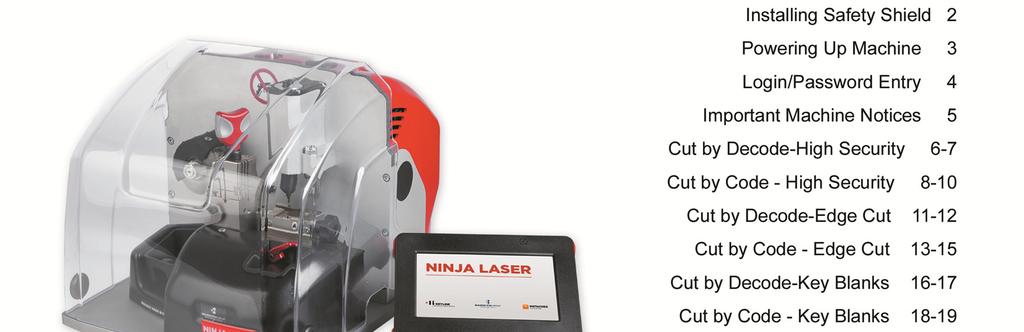
3 INSTALLING SAFETY SHIELD 2 Your Ninja Laser safety shield is shipped separate from the machine in order to protect the shield in transit. Please follow the instructions for installing the shield upon receipt before initial use. STEP 1: Remove the Ninja Laser and the shield from the box Locate the 4mm allen wrench in the tool kit STEP 2: Remove the screws on each side of the Ninja Laser and set aside STEP 3: Line up shield on machine so opening is directly over screw hole. Slots must be perpendicular to base. STEP 4: Reinsert screws and tighten down with 4mm allen wrench on both sides. Machine is now ready for use.
 TO POWER THE MACHINE OR MACHINE MOTOR WILL NOT WORK PROPERLY 3 1.")


.")
4 POWERING MACHINE ON/OFF Cable Connection & Powering Machine ON *MOBILE USERS: YOU MUST USE A PURE SINE WAVE INVERTER WITH 1100 WATTS (or greater) TO POWER THE MACHINE OR MACHINE MOTOR WILL NOT WORK PROPERLY 3 1. Attach the 9-pin connector cable to the port on the LEFT SIDE of the console AND to the back of the machine. SECURE WITH ATTACHED SCREWS. Also, connect the black cable to the console and the back of the machine. 2. Attach power cord to back of machine and plug into a properly grounded outlet. 3. Rotate the Emergency Stop button towards the back of the machine until it releases outward. The machine will now begin to start-up. 4. Press down on the ON/OFF button which will illuminate to RED. This process can take up to 4 minutes. Proceed with LOGIN (page 4). Powering Machine OFF At MAIN MENU, select Power button Select YES to log out, then select Power button again at Login screen Select YES to exit


5 LOGIN / PASSWORD ENTRY TIP: Use included stylus with touch screen to ensure accurate selections 4 Select ADMINSTRATOR Leave password screen blank, no default password is set, Select NEXT. To create password, see below. PASSWORD CREATION (OPTIONAL) -Skip this section if you do not want a password- From Main Menu, Select SETUP, then USERS and then CHANGE PASSWORD. At the Change Password screen enter in your new password and confirm (leave Old Password line blank) then select NEXT. Administrator password is now set.
6 IMPORTANT 5 MACHINE CALIBRATIONS DO NOT CALIBRATE THE JAWS. The Ninja Laser is manufactured to highly precise specifications. Machines and consoles are uniquely paired on initial factory setup. All cutter and jaw calibrations have been performed at the factory matching the jaw to the machine thus making calibrations by the user unnecessary. Consoles and machines cannot be swapped with different versions without consenting Keyline technical team for instructions. SAFETY SHIELD The safety shield works in conjunction with the software prompts. The software, before starting some cut and decode procedures, requires the closing of the safety shield. If it is not closed when requested, it will continue to ask its closing. If the user opens the safety shield during an operating phase (for example, when the machine is cutting or decoding a key) it will stop immediately and, at the closing of the shield, the machine will reset the operation and go back to the beginning of the procedure. Make sure to complete all parts of the process (i.e. positioning AC jaw in correct position, securing key on jaw, removing tip stop, etc) at one time, then close the shield before proceeding to the next step. This will avoid having to replicate steps. KEY MATERIAL The Ninja Laser defaults to cutting brass keys as the key material type. If you are cutting a different type of metal key, such as steel, nickel silver or aluminum, you can make the selection in the cutting screen. Please note the Ninja Laser cannot cut or decode any type of plastic key, painted keys or keys made of non-conductive materials. To change the material type, simply touch the BRASS icon on the screen until you reach the desired material; BRASS, STEEL, NiSi (Nickel Silver) or ALU (aluminum) USE OF AFTERMARKET SPARE PARTS Keyline machines require the use of factory original parts. Aftermarket cutters, tracers and adaptors are not recommended and may cause product damage that will void your machine warranty. MACHINE PACKAGING Please retain all machine packaging for transportation purposes. Packaging is specially designed to safely transport the machine and it s components. Keyline is not responsible for providing additional packing material if original boxes are lost, damaged or discarded. WARRANTY INFORMATION In Warranty (within 90 days of purchase): Customer will return machine and Keyline USA will the reimburse shipping charges. Keyline USA will pay the return shipping back to the customer In Warranty (91+ days of purchase): Customer will pay to return the machine to Keyline USA. Keyline USA will pay the return shipping back to the customer Out of Warranty: Customer will pay to return the machine to Keyline USA. Customer will pay the return shipping back to the customer TEMPERATURE Machine operating temperature is between 32 and 104 degrees Fahrenheit.


7 CUT BY DECODE HIGH SECURITY 6 NOTE: Make sure AC Jaw is in DECODE position on jaw carriage as shown in the picture to the right. Decode Metal Keys Only! Do Not Decode Plastic Keys! TIP: DO NOT DECODE PLASTIC KEYS! Only metal keys can be decoded and cut on the Ninja Laser. 1. Select: SETUP Select CARS Select MAKE, then NEXT Select : Cut by Code when prompted Select MODEL, then NEXT Select YEAR RANGE, then NEXT Select DECODE, then select NEXT Insert key on jaw, remove tip stop and close shield, then select NEXT


8 CUT BY DECODE H.S., cont. 7 Confirm jaw position, select OK Select OK Confirm tip stop tool removal Decoding in process Decode complete; Select OK Depths and key code displayed Select NEXT, then proceed with cutting the key by code (refer to Page 8 CUT BY CODE-H.S., cont. to proceed with cutting


9 CUT BY CODE HIGH SECURITY 8 NOTE: Make sure AC Jaw is in CODE position on the jaw carriage as shown in the picture to the right. TIP: Cutting a test key is also recommended on first use to verify correct key cutting procedure. 1. Select: SETUP Select CARS Select MAKE, then NEXT Select : Cut by Code when prompted Select MODEL, then NEXT Select YEAR RANGE, then NEXT Select CODES, then select NEXT Enter code, (ex. K041), select NEXT

.")

10 CUT BY CODE HIGH SECURITY,cont. 9 Key depths appear, select NEXT Make sure jaw is in cutting position Insert key correctly on jaw, paying close attention to tip stop position (shown in BLUE). Tighten down key, then remove tip stop. Close shield. When key is ready, select CUT Confirm jaw placement, select OK Select OK Confirm tip stop removal tip stop, select OK
11 CUT BY CODE HIGH SECURITY,cont. 10 Key cutting begins Flip key in jaw, removing key shavings with brush, select OK Confirm removal of tip stop tool, select OK Key cutting begins Cut complete Key cutting complete, select OK. Remove all key shavings from the jaw and select CUT to cut additional keys or HOME to go back to MAIN MENU.
.")
12 CUT BY DECODE EDGE CUT 11 NOTE: When using the edge cut jaw side, the AC jaw (right side) must be removed. Select CARS Select MAKE Select MODEL Select YEAR Select DECODE Insert key correctly on jaw, paying close attention to tip stop position (shown in BLUE). Tighten down key, then remove tip stop. Close shield. When key is ready, select NEXT


13 CUT BY DECODE EDGE CUT, cont. 12 Extract left side tracer as shown Confirm AC jaw removal, select OK Select OK Confirm tip stop removal, select OK Decoding in process Decode complete; select OK Depths and key code are displayed. If proceeding to cutting, retract tracer, then select NEXT to proceed with cutting the key by code (refer to Page 13 CUT BY CODE-EDGE CUT).


14 CUT BY CODE EDGE CUT 13 NOTE: When using the edge cut jaw side, the AC jaw (right side) must be removed. Select CARS Select MAKE Select MODEL Select YEAR Select CODES Enter code and select NEXT Key depths display, select NEXT

15 CUT BY CODE EDGE CUT, cont. 14 Select the correct jaw side as displayed on screen. Jaw can be rotated by pulling up on the base of the jaw and rotating to correct side. Insert tip stop and insert key to correct position as noted in BLUE. Tighten down jaw and remove tip stop. Close shield. Select CUT once ready Confirm AC jaw removal Select OK Confirm tip stop removal Key cutting begins Rotate key and select OK

 Lift the gauge (2)")
16 CUT BY CODE EDGE CUT, cont. 15 Confirm tip stop removal Cut complete, select OK Once key cutting is complete, put additional duplicate key to be cut into jaw and select CUT. If done, select HOME to go to Main Menu. NOTE: if cutting a key with a shoulder stop; Insert the key blank into the jaw (1) Lift the gauge (2) until it is flush with the shoulder stop (4) Tighten the jaw handle (3) to lock the key s position
 must be removed.")

17 CUT BY DECODE KEY BLANKS 16 NOTE: When using the edge cut jaw side, the AC jaw (right side) must be removed. Select KEY BLANKS KEY BLANK menu appears Select desired KEY BLANK, then NEXT Select KEY CODE SERIES, then NEXT Select DECODE Extract left side tracer as shown Insert key on jaw, then remove tip stop. Close shield and select NEXT


18 CUT BY DECODE KEY BLANKS, cont Select: SETUP Select OK Confirm AC jaw removal, select OK Decoding in process Decode complete; select OK If proceeding to cutting, retract tracer, then select NEXT to proceed with cutting the key by code (refer to Page 18 CUT BY CODE KEY BLANKS). Depths and key code displayed

19 CUT BY CODE KEY BLANKS 18 NOTE: Before using the edge cut jaw side, the AC jaw (right side) must be removed. Select KEY BLANKS KEY BLANK menu appears Select desired KEY BLANK, then NEXT Select KEY CODE SERIES, then NEXT Select CODES Enter key code, select NEXT Key depths display, select NEXT


20 CUT BY CODE KEY BLANKS, cont. 19 Select the correct jaw side as displayed on screen. Jaw can be rotated by pulling up on the base of the jaw and rotating to correct side. Insert tip stop (if required) or use shoulder stop and insert key to correct position. Tighten down jaw and remove tip stop. Close shield. Select CUT once ready Confirm AC jaw removal Confirm tip stop removal Key cutting begins Once key cutting complete, put additional duplicate key to be cut into jaw and select CUT. If done, select HOME to go to Main Menu. Cut complete, select OK


21 CUTTER REPLACEMENT H.S Select: SETUP Select SETUP Select UTILITY Select REPLACE CUTTER, make sure appropriate jaw is installed Current cutter installed displays, select YES to continue Jaw carriage moves into position Select OK once complete TO REMOVE CUTTER: 1. Insert red cutter removal tool into slot and rotate until it drops in position. 2. Press down to lock onto cutter. 3. Insert 3mm Allen tool into set screw and once initial release, loosen two complete turns. Remove Allen tool. 4. Remove red rod with cutter attached. 5. Remove old cutter from tool.


22 CUTTER REPLACEMENT H.S., cont Select: SETUP Confirm cutter removal, select OK. Jaw will move into position Confirm no keys or templates are installed on jaw, select OK 1. Select: SETUP Confirm no tip stop is installed, select OK Close the shield and select OK. Jaw moves into position TO INSTALL NEW CUTTER: 1. Insert new cutter on red tool pressing in until cutter clicks into place. 2. Insert into hole on top of machine 3. Rotate until notch on red tool inserts into slot and cutter rests lightly on the silver dot on the jaw. 4. Tighten set screw with 3mm Allen tool. 5. Remove Allen tool and red tool. Select OK once complete
23 CUTTER REPLACEMENT H.S., cont Select: SETUP Close the shield, select OK. Jaw will move into position Select OK to reset cutter counter Utility screen appears, select HOME to go to Main Menu
 2.")
 REMOVE OLD CUTTER: 1. Use 2.")


24 CUTTER REPLACEMENT EDGE CUT 23 WHAT YOU NEED: New replacement cutter (B5500) 2.5mm allen tool (included in tool kit) Steel bar (included in tool kit) 19mm open end wrench (included in tool kit) REMOVE OLD CUTTER: 1. Use 2.5mm allen tool to remove 3 screws that secure black edge cutter cover. 2. Insert steel bar into hole on shield and then through left side of cutter shaft. Rotate the cutter wheel until the steel bar is able to insert all the way through the cutter shaft. 3. Use the 19mm wrench to remove nut. Turn clockwise to loosen. 4. Remove silver spacer in front of cutter, then remove the cutter. INSTALL NEW CUTTER: 1. Install new cutter onto shaft with part number facing forward, then replace silver spacer and nut. Turn counterclockwise to tighten. 2. Remove steel bar, then replace the cover and tighten down screws. 3. Machine is now ready for use.


25 TRACER REPLACEMENT 24 IMPORTANT: Please make sure safety shield is closed before starting initial tracer replacement procedure. 1. Select: SETUP Select SETUP Select UTILITY Select REPLACE TRACER Current tracer installed displays, select YES to continue Remove jaw, then select OK Remove tracer; see instructions on page 23


26 TRACER REPLACEMENT, cont. 25 TO REMOVE TRACER: 1. Use 2.5mm Allen tool to loosen tracer setscrew ½ a turn 2. Pull out tracer. NOTE: You may use pliers to remove tracer if it is bent or broken. Select OK once tracer is removed TO INSTALL NEW TRACER: 1. Install new tracer as far as it will go you cannot go too far. 2. Be sure flat side of tracer is facing right to allow the set screw to seat properly. 3. Tighten set screw. DO NOT OVER TIGHTEN. 4. Select OK once tracer is successfully installed. Install Jaw AC in cutting position, select OK. Utility screen appears, select HOME to go to Main Menu.


27 JAW SETUP TIBBE (H) REQUIRED ITEMS: H Jaw, Tibbe calibration template, 2.5mm allen wrench Select: SETUP Select SETUP Select CALIBRATIONS Select JAW SETUP Select H jaw, then START Remove current jaw, select OK Install jaw H in cutting position (as shown to right), select OK


28 JAW SETUP TIBBE (H), cont. 27 Remove the cutter, select OK Confirm cutter removal, select OK Move jaw to DECODING position, select OK Install 2.5mm as shown in picture, select OK Install cutter until it drops down and rests on top cutter landing dot (shown at left). Tighten cutter set screw. Jaw will move out after selecting OK.


. Close shield and select OK Fig.")
29 JAW SETUP TIBBE (H), cont. 28 Move jaw to cutting position, close shield and select OK Insert Tibbe jaw calibration template completely into jaw (Fig.1). Tighten front set screw with included Allen wrench Fig. 1 Jaw in cutting position with template in 1 position Turn template to position 0 (Fig. 2). Close shield and select OK Fig. 2 Template turned to 0 position. Tighten with left thumb wheel Confirm jaw is in cutting position. Select OK. Machine checks jaw.

30 JAW SETUP TIBBE (H), cont. 29 Move jaw to decoding position Calibration complete. Select OK Select SAVE icon Select YES to save calibration Repeat jaw calibration a second time to confirm the values are within +/- 2. Then proceed to CUT BY CODE TIBBE.


31 CUT BY CODE TIBBE (H) Select: SETUP Select CARS Select Make, then NEXT Select Model then NEXT Select year range and then NEXT Select CODES, then NEXT Enter Code, select NEXT Key depths displayed, select NEXT Insert Tibbe key in 0 position. Select CUT

32 CUT BY CODE TIBBE (H), cont. 31 Remove current jaw, select OK Install jaw H in cutting position, select OK Remove the cutter, select OK Confirm cutter removal, select OK Move jaw to DECODING position, select OK Install 2.5mm cutter, then select OK Move jaw to cutting position, close shield and select OK

, then select OK.")

33 CUT BY CODE TIBBE (H), cont. 32 Confirm jaw is in cutting position Clamp key blank in jaw Follow the machine prompts for each cut position until the first side of key is complete. After cuts are complete, machine will prompt to put key into position 1 (i.e. home position so key can be removed), then select OK. Turn key to position 1, select OK Rotate key 180 degrees and follow prompts to cut second side of key Turn key to position 1 again, select OK Remove key and select OK


34 SOFTWARE UPDATE INSTRUCTIONS SOFTWARE UPDATE VIA USB MEMORY STICK & KEYONLINE WEBSITE WHAT YOU WILL NEED: 33 Console, USB Memory Stick (included with machine), PC with Internet connection NOTE: USB Memory Stick must be blank with no files on it To check your current software version, see Version SW below the Main Menu tab


35 STEP 1: Prepare USB Memory Stick with Update File 34 At MAIN MENU, select SETUP At SETUP MENU, select UPDATES Then select KEYONLINE VIA PC Select YES to Software Update Insert USB Memory Stick, select OK USB stick inserts on right side of console Console prepares software file Remove USB stick, Select OK


36 STEP 2: Install Update File on USB from PC 35 Insert USB stick into USB port on PC then go to On site, double-click CHOOSE FILE Go to File Explorer, locate the drive where the USB stick is assigned and double-click the drive Highlight the.cks file listed and click OPEN The.cks file now appears in the box on the Keyonline site, then click REQUEST UPDATE A pop-up box will appear that says This action may take some time Click OK when this message appears Software package creation will begin. This take up to a few minutes depending on your Internet speed.

37 STEP 2, cont: Install Update File on USB from PC 36 Package creation completed should appear. You will be prompted with a pop up at the bottom of the screen, that shows the downloaded file. Click on the drop down arrow to the right of the download file and select OPEN IN FOLDER Once you have the downloaded file folder up, locate the USB drive with the original file you downloaded from the Ninja Laser console. Drag the new file that you created from Keyonline to the USB drive (NOTE: Do not extract the file just drag and drop). The file will begin downloading to the USB stick. Once the update file has finished installing you will then have two items on your USB stick. The original.cks file you downloaded from the USB and the file you downloaded from Keyonline. Safely eject the Removable Disk from your drive. To eject, right click on the drive letter and select Eject. You can now take the USB memory stick back to your console to complete the software update.


38 STEP 3: Complete Software Installation on Console 37 Insert USB into console and select OK Update begins Select YES to confirm update Machine will re-boot and power back up as update continues Update continues; progress bar on bottom Update successful; select OK


39 FAVORITES 38 Selecting Favorites helps bypass Make, Model and Year selections that you most commonly use to get you right to the Code/Decode/Direct screen Go through the menu and select the Make, then the Model, then the Year and Code Series range of the vehicle you want to save a favorite for At Main Menu, select Cars Select the Star icon from the top Menu bar Enter the text for the Favorite you are adding, then select Next Select YES to save custom info From the Main Menu select Favorites and the saved favorite will now be listed. This can be selected for future keys to bypass the Make, Model and Year selection and go right to Decode/Codes/Direct menu
40 NINJA LASER SPARE PARTS 39 Description Universal 2.5mm cutter (WC011A) Part Number B mm Carbide Cutter Universal Tracer (TL003) Calibration Tracer (TL000) Magnetic Tip Stop Cutter setup blanks (5pk) Jaw calibration template "AC" Clamp H" Clamp - Orange (must have dot indentation on bottom of jaw) 3mm T-wrench (Long) Red Cutter Removal Tool Ninja Laser B Clamp Ninja Laser D Clamp Console / Base Support Console Arm Support Infiniti Adaptor (AD02) Lexus 80K Adaptor (AD03) Infiniti Adaptor (AD05) Edge cut tip stop Anti-glare console screen protector 4GB USB Flash Drive for Software Updates B5500 RIC09483B RIC09912B B3405 B3319 B3354 OPZ09734B OPZ09523B B3316 B3315 OPZ09781B OPZ09783B RIC09940B OPZ09454B B3352 B3379 OPZ10269B OPZ09874B B9979 PROMO Keyline USA. All Rights Reserved.
994 LASER QUICK GUIDE
 994 LASER Quick-Start Guide CONTENTS Machine set-up & password entry Jaw calibration Cut by code & decode How to replace the cutter & change the tracer Short form instructions Replacemente parts list IMPORTANT
BD Laser User Guide * IMPORTANT * PLEASE READ THE FOLLOWING INSTRUCTIONS CAREFULLY AS IMPROPER USE MAY DAMAGE THE MACHINE AND VOID THE WARRANTY.
 BD Laser User Guide * IMPORTANT * PLEASE READ THE FOLLOWING INSTRUCTIONS CAREFULLY AS IMPROPER USE MAY DAMAGE THE MACHINE AND VOID THE WARRANTY. BD Laser arrives ready to use with jaws and cutters preinstalled.
User Guide Instruction Manual
 User Guide Instruction Manual Please wear Safety Glasses at all times while operating this machine. DO NOT attempt to lubricate the machine. Clean only with a brush and or vacuum. Shield must be lowered
Triax A/T QUICK START GUIDE
 Triax A/T QUICK GUIDE Please read all instructions carefully before operating your Triax A/T Key Machine. 1. Preparation A. First remove the Triax A/T machine from its cardboard box and pallet. The machine
FuturaPRO. Electronic Key Cutting Machine
 FuturaPRO Electronic Key Cutting Machine FuturaPRO The Next Generation The Ultimate Electronic Key Cutting Experience The original Futura electronic key cutting machine was the first machine on the market
Rack Installation Instructions
 Rack Installation Instructions Review the documentation that comes with your rack cabinet for safety and cabling information. When installing your server in a rack cabinet, consider the following: v Two
Replacement Instructions
 imac G5 Inverter, 20-inch Replacement Instructions Follow the instructions in this document carefully. Failure to follow these instructions could damage your equipment and void its warranty. Note: Online
Removal and Installation8
 8 Screw Types 8-4 Top Cover Assembly 8-5 Left Hand Cover 8-6 Right Hand Cover 8-10 Front Panel Assembly 8-14 Left Rear Cover 8-15 Right Rear Cover 8-16 Extension Cover (60" Model only) 8-17 Media Lever
How to add a Second Drive to a Mac mini (2012) using the OWC Data Doubler SSD/2.5 Installation Kit
 using the OWC Data Doubler SSD/2.5 Installation Kit") Instructional Video Series How to add a Second Drive to a Mac mini (2012) using the OWC Data Doubler SSD/2.5 Installation Kit Skill Level: Challenging Time to Complete: Approximately 45 Minutes Required
Instructional Video Series How to add a Second Drive to a Mac mini (2012) using the OWC Data Doubler SSD/2.5 Installation Kit Skill Level: Challenging Time to Complete: Approximately 45 Minutes Required
5. Tools. Blue SHARK 123SHARK
 5. Tools 5.1 Edit DSD Presets 5.2 Machine Adjustments 5.3 Custom DSDs 5.4 DSD Specific Adjustments 5.4.1 Cut Styles 5.5 Decode 5.6 Special Function 5.7 Security 31 5.1 Edit DSD Presets The Tools section
Ioline CrystalPress. Quick Start Guide
 Ioline CrystalPress Quick Start Guide The Quick Start Guide is intended to help a new user of the Ioline CrystalPress get everything setup and running quickly. Please note that there are important notices,
OPERATING INSTRUCTIONS:
 List OPERATING INSTRUCTIONS: Preparation For Installation, Product Identification Charging The Batteries ing And Adjusting The Lift Mounting Head s Brackets Mounting Clamps And Quick-Locking Arms Installation
IBM. Rack Installation Instructions
 IBM Rack Installation Instructions Review the documentation that comes with your rack cabinet for safety and cabling information. When installing your server in a rack cabinet, consider the following:
N3150 Installation and Setup Instructions
 IBM System Storage N350 Installation and Setup Instructions Covering the N350 model GC27-426-0 Notices Mail comments to: IBM Corporation Attention Department GZW 9000 South Rita Road Tucson, AZ 85744-000
Owner s Manual For S600 Models
 Owner s Manual For S600 Models Important Product Information The serial number of your new Ghostwriter signature machine is located on the back panel. For future convenience, please record the information
FG-7000 Digital Force Gauge Operation Manual
 FG-7000 Digital Force Gauge Operation Manual Operators should wear protection such as a mask and gloves in case pieces or components break away from the unit under test. Whether the unit is ON or OFF,
Operating manual D434731XA. vers. 2.0
 Operating manual D434731XA vers. 2.0 (c) 2008 SILCA S.p.A. - Vittorio Veneto This manual is written by SILCA S.p.A. All rights reserved. No part of this publication may be reproduced or used in any form
QL-1110NWB. Applications for Use with Computers. Applications for Use with Mobile Devices. Quick Setup Guide (English) NOTE
 NOTE") D00ZC6001 QL-1110NWB Quick Setup Guide (English) Thank you for purchasing the QL-1110NWB Label Printer! Read the Product Safety Guide first, then read this Quick Setup Guide for the correct setup procedure.
D00ZC6001 QL-1110NWB Quick Setup Guide (English) Thank you for purchasing the QL-1110NWB Label Printer! Read the Product Safety Guide first, then read this Quick Setup Guide for the correct setup procedure.
Label Printer Quick Setup Guide QL-800
 Label Printer Quick Setup Guide QL-800 QL-800 Quick Setup Guide (English) Label Printer QL-800 Printed in China D00RPE001 Quick Setup Guide (English) Thank you for purchasing the QL-800! Read the Product
Quick start guide for p5 520 ( )
") Quick start guide for p5 520 (9111-520) 1 Before you begin This Quick start guide contains an abbreviated set of setup instructions designed to help you quickly unpack and set up a standard system. Users
Quick start guide for p5 520 (9111-520) 1 Before you begin This Quick start guide contains an abbreviated set of setup instructions designed to help you quickly unpack and set up a standard system. Users
N3220 Installation and Setup Instructions
 IBM System Storage N3220 Installation and Setup Instructions Covering the N3220 model GA32-2202-01 Notices Mail comments to: IBM Corporation Attention Department GZW 9000 South Rita Road Tucson, AZ 85744-0001
Printhead Replacement and Adjustment Guide for the CD Printer Revision B
 Printhead Replacement and Adjustment Guide for the CD Printer 110553-001 Revision B Rimage Corporation 7725 Washington Avenue South Minneapolis, MN 55439 FAX: (952) 946-4578 Service:(800) 382-8436 (North
To connect the AC adapter:
 Replacing the AC Adapter Replacing the AC Adapter 3 Plug the power cord into a wall outlet. The power indicator turns on. To connect the AC adapter: Connect the power cord to the AC adapter. Power indicator
KM-4800w. Installation Guide
 KM-4800w Installation Guide TABLE OF CONTENTS page 1 Installation Requirements 2 2 Unpacking 3 2. 1 Unpacking 3 2. 2 Confirmation of Accessories 5 3 Leveling the Machine 7 4 Setup of the Roll Deck 9 5
BPL SERIES INSTALLATION INSTRUCTIONS THIS SHEET CONTAINS IMPORTANT SAFETY INSTRUCTIONS. SAVE THESE INSTRUCTIONS.
 BPL SERIES INSTALLATION INSTRUCTIONS Important Warning THIS SHEET CONTAINS IMPORTANT SAFETY INSTRUCTIONS. SAVE THESE INSTRUCTIONS. This product must be installed in accordance with National Electrical
Nikon Focus Drive Manual
 Nikon Focus Drive Manual PRIOR SCIENTIFIC INC., 80 RESERVOIR PARK DRIVE, ROCKLAND, MA 02370-1062 TELEPHONE 781-878-8442 FAX 781-878-8736 WWW.PRIOR.COM Table of Contents Safety Information...1 Unpacking
Section. Service & Maintenance. - Core & Hard Disk Drive (HDD) - Amplifier - Monitor - UPS - Dollar Bill Acceptor - Fan Filter G - 1
 - Amplifier - Monitor - UPS - Dollar Bill Acceptor - Fan Filter G - 1") Section G Service & Maintenance - Core & Hard Disk Drive (HDD) - Amplifier - Monitor - UPS - Dollar Bill Acceptor - Fan Filter G - 1 Core Removal Core & HDD 1. Open the door. 2. Perform shutdown procedure.
Section G Service & Maintenance - Core & Hard Disk Drive (HDD) - Amplifier - Monitor - UPS - Dollar Bill Acceptor - Fan Filter G - 1 Core Removal Core & HDD 1. Open the door. 2. Perform shutdown procedure.
N3240 Installation and Setup Instructions
 IBM System Storage N3240 Installation and Setup Instructions Covering the N3240 model GA32-2203-01 Notices Mail comments to: IBM Corporation Attention Department GZW 9000 South Rita Road Tucson, AZ 85744-0001
Installation and Start-Up Instructions
 EVERVU Touch Screen Display for EVERGREEN 19XR,XRV, 23XRV Chillers with PIC II or PIC III Controls Installation and Start-Up Instructions Part No: 33CNTVIEW CONTENTS SAFETY CONSIDERATIONS......................
Framon Fra-2001 Code Machine. Machine & Software Instruction Manual
 Framon Fra-2001 Code Machine Machine & Software Instruction Manual 1 The FRA2001 Machine When unpacking the carton, be sure to locate the following items in addition to the machine itself: Allen wrenches:
Dell Edge Gateway. Service Manual Series
 Dell Edge Gateway 5000 Series Service Manual Computer Model: Dell Edge Gateway 5000/5100 Regulatory Model: N01G/N02G Regulatory Type: N01G001/N02G001 Notes, cautions, and warnings NOTE: A NOTE indicates
ITL 950C. THE ITL 950C COMPUTER KEY MACHINE Operations Manual
 ITL 950C QRS BCD KLM THE ITL 950C COMPUTER KEY MACHINE Operations Manual ITL 950C Operating Manual TABLE OF CONTENTS INTRODUCTION PAGE * Table of contents 1 * Specifications 2 * Key Functions 3 OPERATION
Dell Inspiron XPS and Inspiron 9100 Service Manual
 Dell Inspiron XPS and Inspiron 9100 Service Manual Dell Inspiron XPS and Inspiron 9100 Service Manual Before You Begin Memory Module, Mini PCI Card, and Devices System Components Subwoofer Bluetooth Card
EXN4000 Storage Expansion Unit Installation and Setup Instructions
 IBM System Storage EXN4000 Storage Expansion Unit Installation and Setup Instructions GC27-2079-02 IBM System Storage EXN4000 Storage Expansion Unit Installation and Setup Instructions GC27-2079-02 Notices
CRESCENDO /7200 G3. Quick Start Guide for Crescendo /7200. Processor Upgrade Card for Power Macintosh 7200/8200 Computers
 CRESCENDO /7200 G3 Processor Upgrade Card for Power Macintosh 7200/8200 Computers Quick Start Guide for Crescendo /7200 System Compatibility At this printing, processor upgrade cards are compatible with
Quick Installation Guide Direct and Transfer Thermal Printer
 Quick Installation Guide Direct and Transfer Thermal Printer Overview The enclosed printer is currently comprised of two models: 203dpi (dots per inch) model 300dpi (dots per inch) model Unpacking 1. Remove
CBT LW 4-PUMP ADD-ON INTERNATIONAL INSTALLATION GUIDE
 CBT LW 4-PUMP ADD-ON INTERNATIONAL INSTALLATION GUIDE 2 General information This manual contains technical information regarding Bayer SeedGrowth Equipment. Please read and understand these instructions
inview 360 Fusion Calibration Guide Safe Fleet September 2018 All rights reserved Document #: XE-SNB1-CAL-PM-R0A
 inview 360 Fusion Calibration Guide CONTENTS Table of Contents Introduction About the AVM............................3 Preparation Calibration Kit............................5 Recommended Tools.......................5
Cutter Option Installation Instructions
 This kit includes the parts and documentation necessary to install the cutter option on the Zebra XiII, XiIII, and XiIIIPlus-Series printers. NOTE: The Cutter Option is not available for the 96XiIII. Adding
Quick start guide for i5 520 ( or )
") Quick start guide for i5 520 (9405-520 or 9406-520) 1 Before you begin This Quick start guide contains an abbreviated set of setup instructions designed to help you quickly unpack and set up a standard
Quick start guide for i5 520 (9405-520 or 9406-520) 1 Before you begin This Quick start guide contains an abbreviated set of setup instructions designed to help you quickly unpack and set up a standard
SPEECH UPGRADE INSTALLATION GUIDE (MODEL 9100)
") SPEECH UPGRADE INSTALLATION GUIDE (MODEL 900) TDN 0700-00062 07/2006 CORPORATE HEADQUARTERS: 522 E. RAILROAD STREET LONG BEACH, MS 39560 PHONE: (228) 868-37 FAX: (228) 868-0437 RMA (RETURN MATERIAL AUTHORIZATION)
SPEECH UPGRADE INSTALLATION GUIDE (MODEL 900) TDN 0700-00062 07/2006 CORPORATE HEADQUARTERS: 522 E. RAILROAD STREET LONG BEACH, MS 39560 PHONE: (228) 868-37 FAX: (228) 868-0437 RMA (RETURN MATERIAL AUTHORIZATION)
GB of cache memory per controller to DS4800 controllers with 8 GB of cache memory per controller.
 IBM System Storage DS4800 Controller Cache Upgrade Kit Instructions Attention: IBM has renamed some FAStT family products. FAStT EXP100 has been renamed DS4000 EXP100, FAStT EXP700 has been renamed DS4000
Unpacking and Installing the Flora 2512 UV Printer. Steps 1: Unscrew the 10mm bolts holding the top. Then remove the top and put in a safe place.
 Unpacking and Installing the Flora 2512 UV Printer Steps 1: Unscrew the 10mm bolts holding the top. Then remove the top and put in a safe place. Step 2: Unscrew 10mm bolts holding the end panels. On the
Power Supply, 17-inch
 apple imac G5 Power Supply, 17-inch Replacement Instructions Follow the instructions in this sheet carefully. Failure to follow these instructions could damage your equipment and void its warranty. Note:
CARD PRINTER PRINTHEAD REPLACEMENT INSTRUCTIONS
 CARD PRINTER PRINTHEAD REPLACEMENT INSTRUCTIONS CAUTION: The discharge of electrostatic energy that accumulates on the surface of the human body or other surfaces can damage or destroy the printhead. Please
Copyright by Silca S.p.A All Rights Reserved. products quality.
 Futura Pro is the only electronic key cutting machine able to duplicate all types of residential and automotive keys (flat, cruciform, laser and dimple keys). * Keys cut with specific optional accessories.
SECURITY MODULE UPGRADE
 SECURITY MODULE UPGRADE TRAVERSE TDN 07103-00232 February 27, 2014 Corporate Headquarters 21405 B Street Long Beach, MS 39560 Phone: (800) 259-6672 Fax: (228) 868-9445 COPYRIGHT NOTICE 2014 Triton. All
Tactical Weather Station Set-Up Guide 1
 Tactical Weather Station Set-Up Guide 1 This is a generic overview of a portable WEATHERPAK 3 meter tripod set-up. Your system may not include all of the components listed, or may have different components.
Written By: Walter Galan
 imac Intel 21.5" EMC 2428 CPU Replacement Replace the CPU in your imac Intel 21.5" EMC 2428. Written By: Walter Galan ifixit CC BY-NC-SA www.ifixit.com Page 1 of 33 INTRODUCTION Use this guide to upgrade
Rocsecure NE52 NAS System
 Rocsecure NE52 NAS System Revision 1.0 Table of Contents Preface... 3 Before You Begin... 4 Safety Guidelines... 4 Packaging, Shipment and Delivery... 4 Chapter 1 Introduction... 5 1.1 Key Features...
Marina HDMI Install Instructions
 10 Mountain View Drive Shelton, CT 06484 P:800.521.3175 F:203.924.6687 www.electri-cable.com 1 The Marina HDMI media sharing product uses 4 HDMI share cables, and a digital switcher to change between HDMI
Installing 6 Indexer: PRS Standard Tools
 888-680-4466 ShopBotTools.com Installing 6 Indexer: PRS Standard Tools Copyright 2016 ShopBot Tools, Inc. page 1 Copyright 2016 ShopBot Tools, Inc. page 2 Table of Contents Overview...5 Installing the
ColorMaxLP Label Roll Rewinder
 ColorMaxLP Label Roll Rewinder 5/2017 INSTALLATION/OPERATOR MANUAL Included: Rewinder Base plate Power supply Power Cord Thumb screws Assembly instructions 1. Install base plate Lift front of printer and
DS-101g+ Disk Station Quick Installation Guide
 DS-101g+ Disk Station Quick Installation Guide ATTENTION Please refer to Chapter 2 Get to know the Hardware in the User s Guide for the detailed button and LED description. Packing List Before you begin,
System Storage EXP3000 Rack Installation Instructions
 System Storage EXP3000 Rack Installation Instructions Review the documentation that comes with your rack cabinet for safety and cabling information. When you install the IBM System Storage EXP3000 in a
OPERATING GUIDE FUTURA PRO ONE FUTURA PRO ONE ABUS
 SOFTWARE OPERATING GUIDE FUTURA PRO ONE FUTURA PRO ONE ABUS INDEX PROGRAM START...5 CHOICE OF KEYBOARD...6 CHANGE PROGRAM LANGUAGE...6 MEASURING UNITS...6 DROP-DOWN MENU...7 1 SEARCHES... 8 1.1 VEHICLE
Thank you for purchasing a ZT-1300 printer! The following guide will help you install the equipment and software that goes with your ZT-1300 printer.
 Thank you for purchasing a ZT-1300 printer! The following guide will help you install the equipment and software that goes with your ZT-1300 printer. It is strongly recommended that you read through the
Click Save to return to the main Setup screen.
 ON-SITE Setup Guide Thank you for purchasing the ON-SITE. This guide will assist you in the setup of the system. You can call for FREE technical support to get help anytime at 757-258-0910. Please note,
Z-Truck (Vertical Moving) Z-truck Flag. Y-Truck (Horizontal Moving) FIGURE 1: VIEW OF THE Z-TRUCK. Flexshaft Assembly
 Z-truck Flag. Y-Truck (Horizontal Moving) FIGURE 1: VIEW OF THE Z-TRUCK. Flexshaft Assembly") Replacing the LCD Cable To remove and replace the LCD Cable you will need the following tools: #2 Phillips screwdriver (magnetic tip preferred) Socket wrench with 10mm socket Removing the Side Panel 1.
Replacing the LCD Cable To remove and replace the LCD Cable you will need the following tools: #2 Phillips screwdriver (magnetic tip preferred) Socket wrench with 10mm socket Removing the Side Panel 1.
Setup Guide. Confirming the Installation Space. Installation space (W x D x H) 70.5 x 66.3 x 61.5 inches (1790 x 1684 x 1560 mm) 23.
 70.5 x 66.3 x 61.5 inches (1790 x 1684 x 1560 mm) 23.") Introductory Information Setup Guide ENGLISH Read this manual before attempting to operate the printer. Keep this manual in a handy location for future reference. Caution Instructions in this Setup Guide
Introductory Information Setup Guide ENGLISH Read this manual before attempting to operate the printer. Keep this manual in a handy location for future reference. Caution Instructions in this Setup Guide
XPS 15 2-in-1. Service Manual. Computer Model: XPS Regulatory Model: P73F Regulatory Type: P73F001
 XPS 15 2-in-1 Service Manual Computer Model: XPS 15-9575 Regulatory Model: P73F Regulatory Type: P73F001 Notes, cautions, and warnings NOTE: A NOTE indicates important information that helps you make better
Quick Start Guide. LabelWriter
 Quick Start Guide LabelWriter 450 Duo Copyright 2010 Sanford, L.P. All rights reserved. Revised 12/10. No part of this document or the software may be reproduced or transmitted in any form or by any means,
SERVICE MANUAL MODEL SSC-301-F (FORMERLY 301-FS) MODEL BLC-301-F (FORMERLY 301-F)
 MODEL BLC-301-F (FORMERLY 301-F)") SSC-301-F OR BLC-301-F-ISSUE4.0 SERVICE MANUAL FOR MODEL SSC-301-F (FORMERLY 301-FS) OR MODEL BLC-301-F (FORMERLY 301-F) CHARGE-A-CALL TELEPHONE Serving the Telephone Industry Since 1930 Communication
SSC-301-F OR BLC-301-F-ISSUE4.0 SERVICE MANUAL FOR MODEL SSC-301-F (FORMERLY 301-FS) OR MODEL BLC-301-F (FORMERLY 301-F) CHARGE-A-CALL TELEPHONE Serving the Telephone Industry Since 1930 Communication
DYNAVISION D2 TM INSTALLATION MANUAL
 DYNAVISION D2 TM INSTALLATION MANUAL Rev 12 Dynavision International 8800 Global Way, West Chester, Ohio 45069 USA EMAIL:info@dynavisiond2.com, WEBSITE: www.dynavisiond2.com, FAX: (905) 294-6327 Unpacking
Removing and Replacing Parts
 Removing and Replacing Parts Preparing to Work Inside the Computer Recommended Tools Screw Identification System Components Hard Drive Fixed Optical Drive Media Bay Devices Memory Modules Mini PCI Card
Panasonic. DVD/DVC Camera Seminar VDR-D100/200/300 and PV-GS29/39
 Panasonic DVD/DVC Camera Seminar VDR-D100/200/300 and PV-GS29/39 Features (VDR-D100~300) DVD Multi DVD-RAM/R/-RW DSC Feature (Disc & SD Card) One Touch Navigation & Joystick Built in Video Light (D105&D200
IBM Systems. Quick start guide for IBM System p5 505 ( )
") IBM Systems Quick start guide for IBM System p5 505 (9115-505) 1 Before you begin This Quick start guide contains an abbreviated set of setup instructions designed to help you quickly unpack and set up
IBM Systems Quick start guide for IBM System p5 505 (9115-505) 1 Before you begin This Quick start guide contains an abbreviated set of setup instructions designed to help you quickly unpack and set up
Printing Your First Page. Attaching the Paper Support. Plugging in the Printer. Checking the Printer
 Printing Your First Page Attaching the Paper Support Checking the Printer Plugging in the Printer Installing the Ink Cartridges Installing the Printer Software Connecting the Printer 4011307 XXX-00 Attaching
Nov. 07, 2013 p. 5 - changed the B axis unit value to from Changed by Randy per Frank s request.
 Correction notes Nov. 07, 2013 p. 5 - changed the B axis unit value to 45.1389 from 40.0000. Changed by Randy per Frank s request. Jan. 22, 2018 p. 5 - changed the B axis unit value and corresponding picture
Original instructions D446068XA vers. 3.0
 FLAT STEEL Operating Manual Original instructions D446068XA vers. 3.0 EN (c) 2016 SILCA S.p.A. - Vittorio Veneto This manual is written by SILCA S.p.A. All rights reserved. No part of this publication
The printer kit contains a TT230SM printer without cutter. The printer kit contains the TT230SMC printer with cutter.
 The printer kit 556-00239 contains a TT230SM printer without cutter. The printer kit 556-00256 contains the TT230SMC printer with cutter. The cutter is required if printing and cutting HellermannTyton
EGX-400/600 ADA Hardware and Software Setup Guide v1.0
 EGX-400/600 ADA Hardware and Software Setup Guide v1.0 EGX-400/600 ADA Hardware and Software Setup Guide This guide covers configuration of the Raster TM Braille Dot cutter and Character cutter. NOTES:
SERVICE BULLETIN No. 9. For CAREpoint EMS Workstation
 SERVICE BULLETIN No. 9 For CAREpoint EMS Workstation Title: Swapping the Touch Screen Monitor for PT 1710MX (EETI) Please read the following instructions before proceeding. Priority: Service Reference:
JLTX Lever and Joystick Replacement Instructions
 JLTX Lever and Joystick Replacement Instructions WARNING THE INCORRECT INSTALLATION OF A LEVER OR JOYSTICK CAN CAUSE AN EQUIPMENT MALFUNCTION FAILURE TO FOLLOW THIS PROCEDURE CAREFULLY COULD RESULT IN
OPTRON mobile. User Guide. magnified vision. Vers. 2.1AL Magnified Vision, Inc. 2013
 OPTRON mobile User Guide Vers. 2.1AL Magnified Vision, Inc. 2013 magnified vision 2 Before operating this device, please read this user guide thoroughly and retain it for future reference. For questions,
Label Printer QL-810W/820NWB. Quick Setup Guide (English)
") Label Printer QL-810W/820NWB Quick Setup Guide (English) Label Printer QL-810W/820NWB Printed in China D00RPG001 Quick Setup Guide (English) Available Manuals Product Safety Guide This guide provides safety
Label Printer QL-810W/820NWB Quick Setup Guide (English) Label Printer QL-810W/820NWB Printed in China D00RPG001 Quick Setup Guide (English) Available Manuals Product Safety Guide This guide provides safety
Upgrade Instructions. P/N Revision A. October Printer Terminal Holder * *
 Upgrade Instructions P/N 96-08-0 Revision A October 000 480 Printer Terminal Holder P/N 96-08-0 Revision A *96080* Instructions This terminal holder connects the INTERMEC R 600 Series and 700 Series Computers
Rack Installation Instructions
 Rack Installation Instructions Review the documentation that comes with your rack cabinet for safety and cabling information. Before installing your server in a rack cabinet, review the following guidelines:
Software Setup Instructions for the Foster Control System used in the Explora Dome Observatories
 Software Setup Instructions for the Foster Control System used in the Explora Dome Observatories Contents Pages 3 & 4 The new tic counter system & home position sensor Page 5 Control Boxes Pages 6-8 Down
apple Service Source Xserve RAID 17 March Apple Computer, Inc. All rights reserved.
 apple Service Source Xserve RAID 17 March 2003 2003 Apple Computer, Inc. All rights reserved. apple Service Source Basics Xserve RAID 2003 Apple Computer, Inc. All rights reserved. Overview Xserve RAID
Shop Fox Fence Kit Installation Instructions:
 Shop Fox Fence Kit Installation Instructions: Please note this installation kit is designed solely for installation on a Shop Fox Classic Fence. Accurate Technology manufactures kits for other saw fences
Biesemeyer Fence Kit Installation Instructions:
 Biesemeyer Fence Kit Installation Instructions: Please note this installation kit is designed solely for installation on a Biesemeyer Commercial Fence. Accurate Technology manufactures kits for other saw
OPTIONAL Universal Loader D708097ZB D736245ZB
 OPTIONAL Universal Loader D708097ZB D736245ZB Automatic feeder Alimentatore automatico Automatisches Zuführmagazin Chargeur automatique Alimentador automático Alimentador automático Automatische toevoereenheid
If technical support is required, please contact Advent Technical Support at
 Document 128-9011 Created 11/21/11 Kit Contents: Item # Qty. Component Description 1 2 Monitor Assembly 2 2 Remote Control 3 1 Cables # 3 4 1 Metal Wire Puller 5 1 Power Cord # 9 6 1 Owners Manual 7 2
COMMERCIAL. VAM24-90-(A) Series
 Series") MERCIAL Bray Controls Commercial Division 13788 West Road, Suite 200A Houston, Texas 77041 BCDSales@Bray.com Phone: 1-888-412-2729 Fax: 1-888-412-2720 www.braycommercialdivision.com Installation Instructions/Part
MERCIAL Bray Controls Commercial Division 13788 West Road, Suite 200A Houston, Texas 77041 BCDSales@Bray.com Phone: 1-888-412-2729 Fax: 1-888-412-2720 www.braycommercialdivision.com Installation Instructions/Part
Zebra XiII-Series Printer Quick Reference Guide
 Zebra XiII-Series Printer Quick Reference Guide Contents Media and Ribbon Loading...67 Media Loading...67 Ribbon Loading...70 Operator Controls...72 Front Panel Keys...72 Front Panel Lights...72 Calibration...74
User s Guide QL-720NW
 User s Guide QL-720NW Be sure to read and understand this guide before using the machine. We recommend that you keep this guide nearby for future reference. Not all models are available in all countries.
First-Time Setup. Summary Steps CHAPTER
 CHAPTER 4 Revised: May 9, 2012, This chapter describes the steps you take to configure the CTS 1300 to use it for the first time and includes the following sections: Required Tools and Accessories, page
READ ME FIRST Windows 98/ME/2000
 READ ME FIRST Windows 98/ME/2000 *DSL Equipment Installation Guide: Alcatel Speed Touch PC *Digital Subscriber Line Part Number: AlcatelPC9x02A Version 1.2-A Table of Contents Follow Steps 1 through 7
READ ME FIRST Windows 95/98/Me/2000
 READ ME FIRST Windows 95/98/Me/2000 *DSL Equipment Installation Guide: Efficient Networks 5260 *Digital Subscriber Line Part Number: 52609x02 Version 1.2-A Table of Contents Follow Steps 1 through 8 to
Table of Contents. Unpacking and Inspection Setup Loading the Media Mount the Printer on the Wall... 16
 WPL25/WHC25 Table of Contents Unpacking and Inspection... 1 Setup... 5 Loading the Media... 6 Mount the Printer on the Wall... 16 LED and Button Functions... 17 Troubleshooting... 18 Unpacking and Inspection
Artisan Technology Group is your source for quality new and certified-used/pre-owned equipment
 Artisan Technology Group is your source for quality new and certified-used/pre-owned equipment FAST SHIPPING AND DELIVERY TENS OF THOUSANDS OF IN-STOCK ITEMS EQUIPMENT DEMOS HUNDREDS OF MANUFACTURERS SUPPORTED
Installing the Printer Software
 4 Printing Your First Page Attaching the Paper Support 7 1 Checking the Printer 6 2 Plugging in the Printer 3 Installing the Ink Cartridges 5 Installing the Printer Software Connecting the Printer 4012581-00
Thank you for purchasing this Factory Service Manual CD/DVD from servicemanuals4u.com.
 Thank you for purchasing this Factory Service Manual CD/DVD from servicemanuals4u.com. Please check out our ebay auctions for more great deals on Factory Service Manuals: servicemanuals4u Dell Inspiron
User Operation Manual: Motorized Valve Controller for Valved Sources
 User Operation Manual: Motorized Valve Controller for Valved Sources Table of Contents BEFORE YOU BEGIN...2 Safety Precautions...2 Product Concerns...2 Specifications...3 Support...3 INTRODUCTION...4 Product
HARMONi G3. Quick Start Guide for HARMONi G3. imac Processor/FireWire Upgrade
 HARMONi G3 imac Processor/FireWire Upgrade imac and Operating System Compatibility The HARMONi G3 imac processor/firewire upgrade is compatible only with imac 233, 266, and 333 MHz models (Revisions A-D);
PoE/FPR Kit for Auto-Sync Time Clock. The Auto-Sync Time Clock is a validated time system with a Web interface and auto discovery.
 ASTCPOEK PoE/FPR Kit for Auto-Sync Time Clock The Auto-Sync Time Clock is a validated time system with a Web interface and auto discovery. The ASTCPOEK Kit provides Power over Ethernet with Full Power
apple Service Source Xserve RAID Xserve RAID and Xserve RAID (SFP) Updated: 25 May Apple Computer, Inc. All rights reserved.
 Updated: 25 May Apple Computer, Inc. All rights reserved.") apple Service Source Xserve RAID Xserve RAID and Xserve RAID (SFP) Updated: 25 May 2004 2003 Apple Computer, Inc. All rights reserved. apple Service Source Basics Xserve RAID 2003 Apple Computer, Inc.
apple Service Source Xserve RAID Xserve RAID and Xserve RAID (SFP) Updated: 25 May 2004 2003 Apple Computer, Inc. All rights reserved. apple Service Source Basics Xserve RAID 2003 Apple Computer, Inc.
QUICK START GUIDE. Android or Windows Tablet. 1 Tower PC. Mount the RazorGage to your Own Table. Assembling the RazorGage ST with RazorGage Table
 QUICK START GUIDE Android or Windows Tablet If you have a Tablet Style Interface (PC or Android) then skip this step. 1 Mount monitor and attach legs to control tower using hardware provided and place
English 1. Package Contents. The package contains the following items. In case there is any missing or damaged item, contact your dealer immediately.
 1. Package Contents The package contains the following items. In case there is any missing or damaged item, contact your dealer immediately. Car Recorder Bracket Quick Start Guide Car adapter 1 2. Product