The UniDataExchanger is a tool that allows an easier handling of the file transfer to and from UniOP operator panels. Contents
|
|
|
- Cameron Rice
- 6 years ago
- Views:
Transcription
1 The UniDataExchanger The UniDataExchanger is a tool that allows an easier handling of the file transfer to and from UniOP operator panels. Contents 1 Introduction Using UniDataExchanger UniDataExchanger Menu Communication Separator character UPLC DLL Directory Handling Recipe Data Recipe Upload Recipe Download Download Boot Download Boot (SSFDC) Download Firmware Download Firmware (SSFDC) Download MIPS Code (SSFDC) Download MIPS Service Download MIPS Service (SSFDC) Download to Second Flash Upgrading Boot in Panels with Boot Version Older than Download Project Download Project (All files) Download Graphics File Upload Project Upload Project Flash Image Trend Buffer Upload Download SVG Files Upload Event List Upload Alarm List UniDataExchanger Command Line Options The UniDataExchanger 1
2 Tn175 Ver Exor International S.p.A. Verona, Italy Subject to change without notice The information contained in this document is provided for informational purposes only. While efforts were made to verify the accuracy of the information contained in this documentation, it is provided as is without warranty of any kind. The UniDataExchanger 2

3 1 Introduction The UniDataExchanger is a stand-alone software tool included in the standard Designer software package or downloadable from the web; it has been developed to easily handle file transfers to and from UniOP operator panels. Recipe data, trend buffers, alarms and events list stored in the memory of the HMI device can be uploaded to a CSV file format; the file can be stored for archival purposes or, in case of recipe data, it can be easily modified and later downloaded again to the panel memory. Also, UniDataExchanger supports the firmware upgrade of the panels and the transfer of project files without the need of the Designer software. Using the files generated by Designer in binary format (ROM Format), UniDataExchanger can transfer them into the UniOP memory. In case you have a Designer 6 installation, the UniDataExchanger is installed together with the Designer package. The executable file can be found into the installation folder of Designer; it can be launched from the Windows Start menu. In case you have downloaded the stand alone installation from the web, to install UniDataExchanger, just create a new folder and copy the files. To start the program, locate the file UniDataExchanger.exe and run it. The UniDataExchanger main window is shown in Figure 1. Figure 1 2 Using UniDataExchanger The UniOP Firmware is composed by two parts: one is called Boot; the second one is called Firmware. The Boot part support only the basic functionality of the panel and it is not sufficient to run a Designer project. The UniDataExchanger 3
4 The version of the Boot present in one panel is visible switching the panel to Configuration Mode and holding the Enter key pressed for one second: the first information line on the top of the display will show the Boot version. The Firmware part is the real HMI engine handling most of the functionality of the product. Upgrading the firmware in a panel means to change all the firmware components present into the panel. Firmware is identified by its Type and by a version number. Different HMI models have different Firmware Type. For panels that run Firmware Type 58/60/61/70/71/72/73 the firmware is composed by four parts: Firmware and Boot (already mentioned) and, in addition, MIPS Code and the MIPS Service files. Note: MIPS Service file for firmware versions 60, 61, 70, 71, 72 and 73 is included in the Boot file. The Command list box allows you to select the operation you want to perform. The Firmware list box specifies the firmware type of the target operator panel. UniOP panels can be organized in several different classes depending on the firmware type. Current UniOP firmware can be divided in the following categories: Firmware Type 32 Firmware Type 33 Firmware Type 37 Firmware Type 52 Firmware Type 53 Firmware Type 54 Firmware Type 55 Firmware Type 38 Boot 38 Firmware Type 38 Boot 39 Firmware Type 38 Boot 48 Firmware Type 58 Firmware Type 60 Firmware Type 60 Boot 61 Firmware Type 70 Firmware Type 70 Boot 71 Firmware Type 70 Boot 72 Firmware Type 70 Boot 73 The Firmware Type is always available in the panel identification plate located in the rear cover of the device. There are some exceptions for FW38/60/61/70/71/72/73 panels. Exceptions are explained below, The Firmware Type is indicated as S/W V.. The operator panels using firmware type FW38 can be equipped with three different CPU boards. Due to differences in the hardware, different Boot modules may be required; Boot 38, 39 or 48. All panels using Boot 38/39/48 are operating with the same FW type 38. The panels can be recognized from the information on the label: Boot 38 + Firmware 38 Boot 39 + Firmware 38 Boot 48 + Firmware 38 Hardware 38A Hardware 38B Hardware 48A The UniDataExchanger 4
5 For panels type 60, 61 and 70, 71 the Firmware version reported into the panel identification plate is the same, respectively 60 and 70. Due to different displays type these machines uses 2 different Boot files. The general rule used to recognize the Boot type that has to be downloaded into Fw 60 and Fw 70 panels is: TFT display = Boot 60/70 STN or B&W display = Boot 61/71 Currently the only HMI models that use Boot type 61 are: etop05eb etop11eb etop32b Currently the only HM models that use Boot type 71 are: etop05c etop11c The Boot type 72 and 73 are used only for specific HMI models. Currently the only HMI model that uses Boot type 72 is: ebis34c Currently the only HMI models that use Boot type 73 are: ex570 NA03 ex840 NA06 The Firmware files are normally stored using a naming convention as described in Table 1. Hardware Type Firmware Type Boot Filename Firmware Filename 33A 32 FWT3BL32.BIN FWT3DL32.BIN 33A 33 FWT3BL33.BIN FWT3DL33.BIN 33A 37 FWT3BL37.BIN FWT3DL37.BIN 39C 52 FWT3BL52.BIN FWT3DL52.BIN 40C 53 FWT3BL53.BIN FWT3DL53.BIN 45A 54 FWT3BL54.BIN FWT3DL54.BIN 55A 55 FWT3BL55.BIN FWT3DL55.BIN 38A 38 with Boot Type 38 FWT3BL38.BIN FWT3DL38.BIN 38B 38 with Boot Type 39 FWT3BL39.BIN FWT3DL38.BIN 48A 38 with Boot Type 49 FWT3BL49.BIN FWT3DL38.BIN Table 1 For Hardware Type 58/60/61/70/71/72/73 the firmware files format is the same used by Designer (long filename); those files are normally stored using a different naming convention as described in Table 2. The UniDataExchanger 5

6 FW Type Boot Filename Firmware Filename MIPS Code Filename MIPS Service Filename 58 Boot bin Firm bin Mips bin Mser bin 60 Boot60-540L00-05.bin Firm60-540L00-05.bin Mips60-540L00-05.bin 61 Boot61-540L00-05.bin Firm60-540L00-05.bin Mips60-540L00-05.bin 70 Boot bin Firm bin Mips bin 71 Boot bin Firm bin Mips bin 72 Boot bin Firm bin Mips bin 73 Boot bin Firm bin Mips bin Table 2 Note: The long filename naming convention includes in the firmware name also the firmware version. For example in the string Boot bin the number indicates the firmware version Note: MIPS Service file for firmwaretypes 60, 61, 70, 71, 72 and 73 is included into the Boot file; so, no MIPS Service file is available for these firmware Types. Note: UniDataExchanger does not support transfer of firmware files to SSFDC memory cards. 2.1 UniDataExchanger Menu The Options Menu contains some general settings of the program. This menu is shown in Figure 2. Figure 2 The UniDataExchanger 6

7 2.1.1 Communication Tech-note The menu item Communication allows the definition of the communication port of the computer used to connect to the panel. The dialog box is shown in Figure 3 below. Figure 3 If you select serial communication, you can select the COM port; to connect to one serial port you will need one of the standard communication cables CA02 or CA114. The second choice is the Ethernet communication, to select communication with a particular device you need to click on Pick UniOP button, and then a list of all the IP addresses of the panels connected via Ethernet will be shown. Now you can select the panel you need to work with. See Figure 4 below for an example. Alternatively you may enter an IP address manually. The UniDataExchanger 7

8 Figure 4 Third choice is UniLOAD, when this is selected the range of UniDataExchanger commands that can be selected from the main window is restricted to Upload Recipe Data and Download Recipe Data. Fourth choice is USB; this allows selecting a disk from where you can retrieve the data. As for UniLOAD when this option is selected the range of UniDataExchanger commands that can be selected from the main window is restricted to Upload Recipe Data and Download Recipe Data Note: Using a serial connection UniDataExchanger can connect to a panel only if it is in Configuration Mode. When connecting with Ethernet, panels can respond to UniDataExchanger also when they are in Operation Mode. Note: To use the Ethernet connection you must have either a panel with a built-in Ethernet port or use a TCM10/ SCM11/SCM12 module; firmware version older than 5.30 cannot support Ethernet programming. Note: The storage of Recipe data on SSFDC or USB driver is supported only by FW 70, 71, 72 and 73 panels starting from firmware version 5.90 and Designer Separator character The Separator Character entry allows defining the character used as a separator when preparing the recipe data file in CSV format. Figure 5 shows the Define Separator character dialog box. The UniDataExchanger 8

9 Figure 5 The Start after Download option defines if a start command must be sent to UniOP panel after a file download. It is the option equivalent to the one available in the Designer Transfer/Option dialog. In order to properly upload Recipe Data Items from the panel and displaying the addresses of the data items, UniDataExchanger needs the reference to a directory where the Designer D32UPLCxxx.DLL files are installed UPLC DLL Directory The UPLCDL Directory entry in the Preferences menu may be used to specify where the Designer D32UPLCxxx.DLL files are located in the computer. If the computer running UniDataExchanger does not include Designer, the information included in the CSV file could not be completed. 2.2 Handling Recipe Data Recipe data is uploaded from the RAM memory storage in the panel; this means that if the user has already changed the recipe default values defined in the Designer project, the upload process retrieves the changed values. Recipe data is downloaded to the RAM memory storage in the panel. On panels type FW 70, 71, 72 and 73, starting from firmware version 5.90 and Designer version 6.07 the recipe data is stored directly into the flash memory of the panel and not in RAM; the data can be also copied on SSFDC or USB disk and uploaded/downloaded directly from/on these supports. Note: Recipe data handling with UniDataExchanger is supported by UniOP firmware version 4.44 and higher. Note: For a correct management of the recipe data the UPLC DLL Directory must be set correctly, for more information refer to chapter Recipe Upload From the Commands list box select the Upload Recipe Data and click the Start button. The UniDataExchanger will prompt you for a target directory where the CSV files has to be stored and for a filename. The UniDataExchanger 9

10 An example of the result is shown in Figure 6; the example is made using the Modbus Slave communication driver. The Recipe Data is configured in Page 1; there are 5 recipe variables and 5 parameter sets. Figure 6 Microsoft Excel can support a maximum of 256 columns. This it means that when you make an upload from panel that has a recipe with 255 parameter sets, the last set is truncated. As a workaround, you should use another program to modify your recipe data Recipe Download From the Commands list box select the Download Recipe Data and click the Start button. The UniDataExchanger will ask you the location of the source CSV file. This file must be in the same format as the one shown in the Figure Download Boot The Download Boot command allows the upgrade of the Boot part of the panel firmware by overwriting the same memory area already occupied by the existing Boot. Note: Download Boot is supported by the panel if the existing boot is version V4.24 or newer for all firmware types except FW37. Firmware Type 37 only supports instead Boot to Boot starting from Boot version V4.40. The proper firmware type must be selected in the Firmware list box. When the Start button is pressed the UniDataExchanger asks for the source file. Note: Download Boot transfer is a critical operation. Since the file will be copied overwriting the existing Boot, if a power down occurs during the transfer, the panel could become unusable. At the end of the Boot download the panel will automatically restarts itself; do not cycle the The UniDataExchanger 10
11 power of the unit in this phase and wait for the completion of the automatic restart of the operator panel.. The Boot-to-Boot command operates directly on the Firmware Flash in the part already occupied by the existing Boot. 2.4 Download Boot (SSFDC) The Download Boot (SSFDC) command transfers to the SSFDC a Boot file. This command requires the proper selection of the firmware type in the Firmware list box and the selection of the proper binary file. Note: Download Boot (SSFDC) command performs only a download of the file, the upgrade of the Boot version of the panel must be performed manually on the panel after the download. Note: The Boot upgrade operation on panel is supported only if the existing boot is version V4.24 or newer for all firmware types except FW37. Firmware Type 37 only supports instead Boot to Boot starting from Boot version V4.40. Note: Upgrade Boot operation on panel is a critical operation. Since the file will be copied overwriting the existing Boot, if a power down occurs during the transfer, the panel could become unusable. At the end of the Boot upgrade the panel will automatically restarts itself; do not cycle the power of the unit in this phase and wait for the completion of the automatic restart.of the operator panel. 2.5 Download Firmware The Download Firmware command transfers to the panels a Firmware file. This command requires only the proper selection of the firmware type in the Firmware list box and the selection of the proper binary file. 2.6 Download Firmware (SSFDC) The Download Firmware (SSFDC) command transfers to the SSFDC a Firmware file. This command requires the proper selection of the firmware type in the Firmware list box and the selection of the proper binary file. Note: Download Firmware (SSFDC) command performs only a download of the file, the upgrade of the Firmware version of the panel must be performed manually on the panel after the download. 2.7 Download MIPS Code (SSFDC) The Download MIPS Code (SSFDC) command transfers to the SSFDC a MIPS Code file. This command requires the proper selection of the firmware type in the Firmware list box and the selection of the proper binary file. The UniDataExchanger 11
12 Note: The MIPS Code file is needed only into the HW58/60/61/70/71 machines. 2.8 Download MIPS Service The Download MIPS Service command transfers to the panels a MIPS Service file. This command requires the proper selection of the firmware type in the Firmware list box and the selection of the proper binary file. Note: The MIPS Service file is needed only into the HW58/60/61/70/71/72/73 machines and only starting from Firmware version Note: The MIPS Service file for HW60/61/70/71/72/73 is included into the Boot file starting from Firmware version 5.40; so the MIPS Service binary files version 5.40 or newer are not available individually. 2.9 Download MIPS Service (SSFDC) The Download MIPS Service (SSFDC) command transfers to the SSFDC a MIPS service file. This command requires the proper selection of the firmware type in the Firmware list box and the selection of the proper binary file. Note: The MIPS Service file is needed only into the HW58/60/61/70/71/72/73 machines and only starting from Firmware version Note: The MIPS Service file for HW60/61/70/71/72/73 is included into the Boot file starting from Firmware version 5.40; so the MIPS Service binary files version 5.40 or newer are not available individually Download to Second Flash The Download to Second Flash command downloads any binary file to the UniOP project Flash located in its project Flash socket. This command is useful when the project Flash socket is used like a programmer. Selection of the correct Firmware type in the Firmware list box is fundamental for proper operation Upgrading Boot in Panels with Boot Version Older than 4.24 In case the panel has Boot version older than V4.24, it does not support the Boot-to-Boot feature. If a Boot upgrade is required in this case, the only way to proceed is preparing a new memory chip using the panel like a flash programmer to load to a new 512KB memory with the necessary files. For example, using the Download to Second Flash command is possible to load to the memory inserted in the project memory socket of the panel, a certain Boot file. This memory can then be used as Firmware memory of the UniOP; at power up the panel will start in Boot Mode showing the Boot The UniDataExchanger 12

13 version in its first line; in this status UniOP is ready to accept the Firmware file download through the Download Firmware command Download Project The Download Project command can be used to download to the UniOP panel a ROM file prepared with the Designer software. The ROM file must be created specifying in Designer the memory media and the inclusion of Project and Protocol as shown in the example of Figure 7. The dialog box below is part of Designer Transfer options. Figure 7 Note: In this case it is very important to choose the correct memory type and size. Note: The FW type 58/60/61/70/71/72/73 projects are composed from a ROM file and some other files like SVG, GFX etc... An apposite command called Download Project (All files) (See chapter 2.10) has been created to download the projects for those HW types using UniDataExchanger Download Project (All files) For FW type 58/60/61/70/71/72/73 the ROM folder created by Designer contains a set of files with all the project components such as SVG files, graphics and fonts. The Download Project (All files) command supports the download of all the project files in a single session. The file.rom has to be selected when you launch the command, then UniDataExchanger automatically takes and downloads all the other needed files into the panel Download Graphics File The Download Graphics File Command transfers the Designer XRM file produced together with the ROM file when the Project is made for a Firmware Type 37 panels. In this case the graphics information is in fact not included in the project and they have to be downloaded to the memory in the panel separately. The UniDataExchanger 13
14 2.14 Upload Project Tech-note The Upload Project command can be used to upload the project present into the UniOP panel as a ROM file. Note: Using the Upload Project command will upload ONLY the project file, the protocol is not uploaded. So if you need to download the ROM file obtained into a panel the protocol file must be already present into the panel, otherwise the panel will not enter Operation Mode Upload Project Flash Image The Upload Project flash image command uploads the entire content of the Project flash as a BIN file. This command can be used to have a backup file of the project contained into a panel; the obtained BIN file will contain all the project files and also the protocol file. The Download to second flash command must be used to download the BIN file into a panel. Note: This command can be used with all the panels that have a Project flash so: FW 32, 33, 52, 53, and Trend Buffer Upload The Trend Buffer Upload command allows retrieving from the panel the trend buffer information stored in its internal RAM Memory and generates a CSV file with the timestamp and data information. Note: Trend Buffer Upload commands requires firmware V5.00 or above Note: Starting from UniDataExchanger version the number of valid samples is reported into the uploaded file. If the trend buffer is not full at upload time all the not valid values are recognizable from the (not valid) voice reported on those voices. Example: ;Trendbuffer :New Buffer ;Number of samples : 3000 (941 of them are valid) :17:24, :17:25, :17:26, :17:27, :17:28,0,(not valid) :17:29,0,(not valid) :17:30,0,(not valid) Note: For a correct management of the trend data, the UPLC DLL Directory must be properly set; for more information refer to chapter The UniDataExchanger 14
15 2.17 Download SVG Files The Download SVG Files command allows transferring to a FW58 unit the SVG components of its Designer application. SVG files are normally temporary created by Designer at the download time and later deleted. SVG files can be created by Designer using the Save as command available from the file menu and selecting the ROM file option in the File Type combo box. When saving the ROM file, Designer creates a directory named with the project name and adding to it the extension.rom. Inside this directory Designer stores all the SVG files programmed in the project (files with.svg extension) and an additional ASCII file (with extension.svg-proj ) which contains the list of all the SVG components of the current project. When starting the SVG download, UDE needs this ASCII file to perform the SVG file download. Note: The support in Designer for the.svg-proj file is included starting from version 6.01(07) and above Upload Event List The Upload Event List command creates a CSV file containing the following information: Event type Number of the alarm Time From the Commands list box select the Upload Event List and click the Start button. The UniDataExchanger will prompt you for a target directory where the CSV files has to be stored and for a filename. Note: Upload Event list command requires firmware version V5.30 or above. Note: With Serial connection this command can be used only when the panel is in Configuration Mode, returning into Operation Mode by pressing the enter key, will clear the event list. To preserve the list, the panel must be reset with a power cycle Upload Alarm List The Upload Alarm List command creates a CSV file within the following information: Alarm number Static flags Dynamic flags On time Off time Link flags Log flags From the Commands list box select the Upload Alarm List and click the Start button. The UniDataExchanger will prompt you for a target directory where the CSV files has to be stored and for a filename. The UniDataExchanger 15
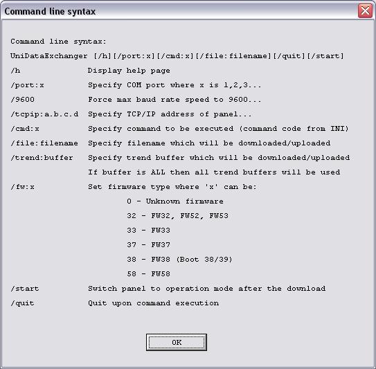
16 If some alarms are currently active you can choose if you want to upload all the alarms actually configured or only the active alarms. Note: Upload Alarm list command requires firmware version V5.30 or above. Note: The alarm list is only available in Operation Mode; this command works only with the Ethernet connection. 3 UniDataExchanger Command Line Options Starting from version , the UniDataExchanger software tool supports some command line options; the program can be launched and operated using batch files. The command line syntax is the following: UniDataExchanger [/h][/port:x][/9600][tcpip:a.b.c.d][/cmd:x][/file:filename][/trend:b uffer][/fw:x][/quit][/start] The table shows the list of supported command line options: /h Displays the help page /port:x Specifies the COM port number to be used for serial transfers where x is 1, 2, 3, /9600 Forces the maximum baud rate to 9600 baud /tcpip:a.b.c.d Specifies the IP address of the panel for Ethernet transfers /cmd:x Specifies the command to be execute where x is the ordinal number of the command as specified in the UniDataExchanger.ini file /file:filename Specifies the name of the file to be downloaded or the name assigned to the uploaded file /trend:buffer Specifies the trend buffer number to be uploaded /fw:x Specifies the firmware type according to the following list: 0 unknown 32 FW32, FW52, FW53 33 FW33 37 FW37 38 FW38 (Boot 38/39) 58 FW58, FW60 /start Specifies to send the start command at the end of the file transfer /quit Specifies to close the UniDataExchanger application after command has been completed. Table 3 The UniDataExchanger 16
17 The UniDataExchanger 17
Contents 1. Introduction
 The UniDataExchanger The UniDataExchanger is a tool that allows an easier handling of the file transfer to and from UniOP operator panels. The program supports the transfer of recipe data and UniOP firmware
Getting Started with UniOP B Series Panels
 Getting Started with UniOP B Series Panels This document contains all you need to know to get quickly started with the new B-generation UniOP panels. Contents 1 The New Hardware Platform for UniOP Panels...3
Newsletter. Communicate and Stay in Control. In This Issue
 The year 2005 started with the introduction of a major step in the UniOP products. New hardware, new software and new solutions to help you stay ahead in the market. In This Issue Ethernet Connectivity
Getting started with JMobile Suite
 Getting started with JMobile Suite This documents includes a brief presentation of the JMobile HMI and explains in few steps how to get started with it Sitek S.p.A. Tn294 Ver. 1.00 Copyright 2008 Sitek
Connecting UniOP to Moeller Easy800
 Connecting UniOP to Moeller Easy800 This Technical Note contains all the information required to connect the UniOP panels to a Moeller Easy800 controller. Sitek S.p.A. Tn189 Ver. 1.01 Copyright 2008 Sitek
Ethernet Connectivity for UniOP
 Ethernet Connectivity for UniOP This document describes the new Ethernet connectivity solutions for UniOP. The new features are initially described in this separate manual; the information will be integrated
Updating Systems Components in UniOP Series 400 Products
 Updating Systems Components in UniOP Series 400 Products This document describes how to update the system components of the UniOP Series 400 HMI products, including Operating System and run-time software.
Connecting UniOP as a Modbus Slave
 Connecting UniOP as a Modbus Slave This Technical Note describes the UniOP implementation of the Modbus RTU slave protocol. Using this communication driver, multiple UniOP HMI panels can be connected to
UniOP Command Summary
 Tech Note UniOP Command Summary Description of the UniOP standard command set Exor International S.p.A. SN024 Ver. 1.3 Copyright 2014 Exor International S.p.A. Verona, Italy Subject to change without notice
Connecting UniOP Using Generic Modbus RTU
 Connecting UniOP Using Generic Modbus RTU This Technical Note contains the information needed to connect UniOP to control devices using the Modbus RTU standard protocol over a serial communication link.
Connecting UniOP to Unidrive SP with Modbus CMP Protocol
 Connecting UniOP to Unidrive SP with Modbus CMP Protocol This Technical Note contains the information needed to connect UniOP to CT Unidrive SP drives using the Modbus CMP communication protocol. CMP is
Connecting UniOP to Galil/Yaskawa controllers
 Connecting UniOP to Galil/Yaskawa controllers This Technical Note contains the information needed to connect UniOP operator panels to Galil s DMC series controllers and Yaskawa s SCM series controllers,
Connecting UniOP as Modbus/TCP Server
 Connecting UniOP as Modbus/TCP Server This Technical Note describes the UniOP implementation of the Modbus/TCP Server protocol. Using this communication driver, multiple UniOP HMI panels acting as Servers
Connecting UniOP to Beckhoff ADS Ethernet
 Connecting UniOP to Beckhoff ADS Ethernet Connecting UniOP to Beckhoff controllers via ADS Ethernet. Sitek S.p.A. ptn0303 Ver. 1.0 Copyright 2009 Sitek S.p.A. Verona, Italy Subject to change without notice
Python Boot Manager PC Interface for loading Python scripts 30/08/07
 PC Interface for loading Python scripts Contents 1.1 Scope... 3 1.2 Introduction... 3 1.3 Using Python Boot Manager Application... 3 1.3.1 Reading the memory... 4 1.3.2 Writing the memory... 5 1.3.3 Flashing
CANopen HMI Communication Driver for JMobile
 CANopen HMI Communication Driver for JMobile This Technical Note contains the information needed to connect the HMI to control devices using the CANopen protocol with HMI profile. Exor International S.p.A.
Connecting UniOP to Fatek Controllers with Facon Protocol
 Connecting UniOP to Fatek Controllers with Facon Protocol This Technical Note contains the information required to connect UniOP to Facon PLC controllers via a serial communication line. The Facon PLC
IndustrialPro Routers (SN/RAM Series)
") Wireless Modems Including 67xx LTE Models Migration and Advanced Firmware Update Procedures Version 3.13/4.13 December 2012 CHANGE HISTORY Version Date Description 3.13 December 20, 2012 SN/RAM Release
Wireless Modems Including 67xx LTE Models Migration and Advanced Firmware Update Procedures Version 3.13/4.13 December 2012 CHANGE HISTORY Version Date Description 3.13 December 20, 2012 SN/RAM Release
Profibus DP Driver for JMobile
 Profibus DP Driver for JMobile This Technical Note contains the information needed to connect the HMI to control devices using the Profibus DP protocol. Exor International S.p.A. ptn0422 Ver. 1.01 Copyright
DL User s Manual
 DL Sm@rtSet User s Manual DL Sm@rtSet USER'S MANUAL DATALOGIC S.p.A. Via Candini, 2 40012 - Lippo di Calderara di Reno Bologna - Italy DL Sm@rtSet Ed.:11/2003 This manual refers to software version 1.40
Using UniOP HMI panels with Galil controllers
 Application Note #5431 Using UniOP HMI panels with Galil controllers EXOR Electronics R&D offers the UniOP etop series HMI touch screen panels, which can effectively interface serially with Galil DMC 2x00
( ) old style CPU board ( ) new style CPU board. Circled items show differences for each board
 old style CPU board ( ) new style CPU board. Circled items show differences for each board") IJ3000 Controller IJ3000 Firmware Upgrade Process 5760-136 Revision D Page 1 of 12 These instructions assume you already know how to change the IP address of your computer, create directories and copy
IJ3000 Controller IJ3000 Firmware Upgrade Process 5760-136 Revision D Page 1 of 12 These instructions assume you already know how to change the IP address of your computer, create directories and copy
Connecting UniOP to CoDeSys Controllers via Ethernet
 Connecting UniOP to CoDeSys Controllers via Ethernet This Technical Note contains the information required to connect UniOP panels to controllers based on the 3S CoDeSys PLC system using Ethernet communication.
Fisher ROC Plus Serial Driver Help Kepware Technologies
 Fisher ROC Plus Serial Driver Help 2014 Kepware Technologies 2 Table of Contents Table of Contents 2 5 Overview 5 Channel Setup 6 Device Setup 7 Tag Import Settings 7 Address Specification 8 Operator Identification
Nova series update F/W & Boot code from Boot Utility
 Nova series update F/W & Boot code from Boot Utility Purpose: Update firmware/boot code from Boot Utility Product Affect: Nova 20S, Nova 20R, Nova 26S, Nova 26R, Nova 27S, Nova 29S, Nova 30S, Nova 30R,
Connecting UniOP to Simatic S7 Profibus
 Connecting UniOP to Simatic S7 Profibus This Technical Note contains all the information required to connect the UniOP panels to a Profibus DP system with a Simatic S7 master and to take advantage from
Mitsubishi FX Ethernet Driver for JMobile
 Mitsubishi FX Ethernet Driver for JMobile This document contains the information needed to connect the panels to Mitsubishi FX Series controllers using an Ethernet connection to the FX3U-ENET module. EXOR
JMobile Suite User Manual
 JMobile Suite User Manual This document contains information for JMobile Suite on-line help, accessible from JMobile Studio\Help command Sitek S.p.A. PTn343 Ver. 1.26 Copyright 2011 Sitek S.p.A. Verona,
Eaton BladeUPS Display Firmware Upgrade. UPS model : Bladeups. Display Firmware Upgrade Procedure. Date : 02/10/2017. Page 1/page total/13
 UPS model : Bladeups Date : 02/10/2017 Page 1/page total/13 Contents 1. Download the firmware 2. UPS connection 3. Perform the firmware upgrade 4. Batch file upgrade procedure 5. Firmware release notes
SYNERGY. Supervision and energy management software INSTRUCTION MANUAL
 SYNERGY Supervision and energy management software INSTRUCTION MANUAL INDEX 1 INTRODUCTION... 4 2 HARDWARE AND SOFTWARE REQUIREMENTS... 4 3 SETUP... 4 4 SYNERGY LOGIN AND USERS... 5 4.1 Users... 5 4.2
Starter Kit Manual. Table of Contents
 Starter Kit Manual Table of Contents Chapter 1 Introduction of UT Series Starter Kits 1.1 General Information about UT Series Starter Kits... 1-2 1.1.1 Components of UT Series Starter Kits... 1-2 1.2 System
Configuration Guide. Upgrading AOS Firmware L1-29.1D July 2011
 61200990L1-29.1D July 2011 Configuration Guide This configuration guide explains how to update your ADTRAN Operating System (AOS) firmware using the AOS Web-based graphical user interface (GUI) with Trivial
FlashMaxII Operation Guide
 FlashMaxII Operation Guide 2015-07-09 Version 1.0 EE Tools, Inc. 4620 Fortran Drive Suite 102 San Jose, CA 95134, USA www.eetools.com sales@eetools.com Tel : (408)263-2221 Fax : (408)263-2230 1 Table of
Upgrading the Server Software
 APPENDIXB This appendix describes how to upgrade or reinstall the Cisco PAM server software, desktop client software, and Gateway module firmware. Contents Upgrade Notes for Release 1.5.0, page B-2 Obtaining
Control with UniOP. Tech-note PN# tn137-2.doc - 29/07/ Ver Contents
 Control with UniOP This manual contains detailed information on the new HMIcontrol option available in UniOP family of HMI products. HMIcontrol is a totally new concept of integrating a state-of-the-art
ABB Modbus RTU Driver for JMobile
 ABB Modbus RTU Driver for JMobile This document contains the information needed to connect the HMI to ABB controllers using the Modbus RTU standard protocol over a serial communication link. Exor International
ASEM System Manager. Introduction TN0012
 Introduction This document describes how to install and use the utility. The utility aims to provide a comprehensive support to manage system specific features, such us clone, selective system components
WizISP Program User Guide for W7100
 WizISP Program User Guide for W7100 version 0.9βeta 2008 WIZnet Co., Inc. All Rights Reserved. For more information, please visit our website at http://www.wiznet.co.kr Copyright 2009 WIZnet Co., Inc.
Connecting UniOP to Profibus DP TI
 Connecting UniOP to Profibus DP TI This Technical Note contains all the information required to connect the UniOP panels to a Profibus DP system with a Simatic TI 555 master and to take advantage from
Typical for either, X is the revision letter, and ### represents the firmware version number e.g., V123 = Version
 Re Flashing Your CRS 500 1:N Redundancy System I. Introduction Make sure to operate the Comtech EF Data CRS 500 1:N Redundant System with its latest available firmware. The CRS 500 1:N Redundancy System
DomiOP ebis504. Tech-note. Highlights
 DomiOP ebis504 The ebis504 compact 4,3 widescreen display completes the ebis series with a no-compromise lowcost product. The built-in dual 100Mb Ethernet interfaces with switch functionality enhance its
User Instructions GB0 23/2011 Fire Detection. Servit Service and Maintenance Tool
 User Instructions 66571772GB0 23/2011 Fire Detection Servit Service and Maintenance Tool User Instructions 66571772GB0 Fire Detection 2 Contents 1. Getting Started...3 1.1 Installing...3 1.2 License and
CHAPTER 17 COMPILING/SIMULATING/DOWNLOADING A PANEL APPLICATION
 COMPILING/SIMULATING/DOWNLOADING A PANEL APPLICATION 17.1. Compiling an Application... 1 17.1.1. Compiling an Application...1 17.1.2. Building a Panel Runtime Package...1 17.1.3. Build a List Window...2
CHAPTER 2 BASIC OPERATING SYSTEM CONCEPT MANAGEMENT
 CHAPTER 2 BASIC OPERATING SYSTEM CONCEPT MANAGEMENT Types of User Interface USER INTERFACE Command Interface Menu Interface Graphical User Interface Voice actuated Interface Web- form Interface User interface
Control Techniques Unidrive - Modbus CMP Ethernet Driver for JMobile
 Control Techniques Unidrive - Modbus CMP Ethernet Driver for JMobile This document contains the information needed to use CT Unidrive SP drives using the Modbus CMP communication protocol. CMP is an extension
IndustrialPro Routers (SN/RAM Series) Wireless Modems
 Wireless Modems") Wireless Modems Including SN/RAM-67xx LTE and RAM-9000 families Migration and Advanced Firmware Update Procedures Version 3.20/4.20 February 2015 CHANGE HISTORY Version Date Description 3.20 February 17,
Wireless Modems Including SN/RAM-67xx LTE and RAM-9000 families Migration and Advanced Firmware Update Procedures Version 3.20/4.20 February 2015 CHANGE HISTORY Version Date Description 3.20 February 17,
Instructions on how to update the firmware from V4.3.x to V4.4.x
 Instructions on how to update the firmware from V4.3.x to V4.4.x Valid for: S120 with CU320-2 or CU310-2 Hardware prerequisites: The firmware versions that can be used depend on the hardware release of
CREATING PANEL APPLICATIONS
 CREATING PANEL APPLICATIONS 3.1. Setting up the Panel Application... 1 3.1.1. General Settings...2 3.1.2. Custom Settings...5 3.1.3. Activating Multiple Overlapped Buttons by One Touch...7 3.1.4. Specifying
Operating Instructions
 Operating Instructions Downloadmanager 2 and Downloadbox Last update: V5.20180702 3032259208-02-US Read and follow these operating instructions. Keep these operating instructions for future reference.
Manual Software Firmware Loader V1.1
 Manual Software Firmware Loader V1.1 (PC software for Microsoft Windows XP, VISTA, 7, 10) This manual describes the installation of the Firmware Loader PC software and as a support for starting up the
BESTCOMSPlus Software
 9440300990 Rev P 123 General Description BESTCOMSPlus is a Windows -based, PC application that provides a user-friendly, graphical user interface (GUI) for use with Basler Electric communicating products.
Fisher ROC Plus Serial Driver Help Kepware, Inc.
 Fisher ROC Plus Serial Driver Help 2015 Kepware, Inc. 2 Table of Contents Table of Contents 2 5 Overview 5 Channel Setup 7 Device Setup 13 Scan Mode 15 Timings and Timeouts 16 Automatic Demotion 17 Automatic
APPLICATION NOTES. Advanced Graphical Interface - AGI Internal PLC (CODESYS V3) SHENDONG
 SHENDONG") APPLICATION NOTES Advanced Graphical Interface - AGI Internal PLC (CODESYS V3) SHENDONG CODESYS V3 logic running on AGI 300/400 series product Support of Modbus/TCP and RTU communication Use of remote
APPLICATION NOTES Advanced Graphical Interface - AGI Internal PLC (CODESYS V3) SHENDONG CODESYS V3 logic running on AGI 300/400 series product Support of Modbus/TCP and RTU communication Use of remote
Data Manager Software User Manual
 Data Manager Software User Manual CONTENTS 1. Installation of USB Virtual COM Port driver software... 2 2. Installation of Data Manager Software... 2 3. Connecting instrument to a PC (Personal Computer)...
8-1. This chapter explains how to set and use Data Sampling.
 8-1 8. Data Sampling This chapter explains how to set and use Data Sampling. 8.1. Overview... 8-2 8.2. Data Sampling Management... 8-2 8.3. Creating a New Data Sampling... 8-2 8.4. Synchronizing cmt Viewer
Unity Loader V2.3 Readme
 Unity Loader V2.3 Readme Table of Contents 1 SYSTEM REQUIREMENTS... 2 2 SETUP PROCEDURE... 2 2.1 Recommendations before installation... 2 2.2 Unity Loader Setup procedure... 2 2.3 Communication Drivers
SANsurfer iscsi Host Bus Adapter CLI. Table of Contents
 SANsurfer iscsi Host Bus Adapter CLI QLogic Corporation All rights reserved Table of Contents 1 Package Contents 2 Requirements 2.1 Hardware Requirements 2.2 Software Requirements 3 OS Support 4 Supported
LOREX CLIENT 3.0 SOFTWARE MANUAL IRMS Integrated Remote Management Software
 LOREX CLIENT 3.0 SOFTWARE MANUAL IRMS Integrated Remote Management Software Instruction Manual English Version 2.0 Copyright 2007 Lorex Technology Inc. www.lorexcctv.com Table of Contents Overview... -
Eaton BladeUPS Can Bridge Firmware Upgrade. UPS model : Bladeups. Can Bridge Firmware Upgrade Procedure. Date : 02/10/2017. Page 1/page total/14
 UPS model : Bladeups Date : 02/10/2017 Eaton BladeUPS Page 1/page total/14 Contents 1. Download the firmware 2. UPS connection 3. Perform the firmware upgrade 4. Batch file upgrade procedure 5. Firmware
FLASH PROGRAMMER FP-8903 VER 2.00 USER S MANUAL
 FLASH PROGRAMMER FP-8903 VER 2.00 USER S MANUAL FP8903 V2.00 DOC R.2.0 1 TABLE OF CONTENTS SECTION CONTENTS PAGE 1 INTRODUCTION 1.1 MANUAL CONTENTS 03 1.2 PROGRAMMER AND ACCESSORIES 03 2 FEATURES 04 3
Setup support for RAMCHECK. Extensive, context-sensitive On-Line Help and Tutorials. HARD DISK INSTALLATION:
 RAMCHECK OWNER S MANUAL While RAMCHECK is a stand-alone unit, the product includes the RAMCHECK PC Communications programs that allow you to upgrade your RAMCHECK s flash EPROM from our Web site (www.innoventions.com).
7-1. This chapter explains how to set and use Event Log Overview Event Log Management Creating a New Event Log...
 7-1 7. Event Log This chapter explains how to set and use Event Log. 7.1. Overview... 7-2 7.2. Event Log Management... 7-2 7.3. Creating a New Event Log... 7-8 7-2 7.1. Overview The following are the basic
Connecting UniOP to Omron PLCs with the FINS Protocol
 Connecting UniOP to Omron PLCs with the FINS Protocol This Technical Note contains the information needed to connect UniOP operator panels to Omron PLCs using the Omron FINS serial communication protocol.
Rev T 237
 9424200996 Rev T 237 BESTCOMSPlus is a Windows -based, PC application that provides a user-friendly, graphical user interface (GUI) for use with Basler Electric communicating products. The name BESTCOMSPlus
Panasonic FP Serial Driver for JMobile
 Panasonic FP Serial Driver for JMobile This document contains the information needed to connect the panel to control devices using the Panasonic FP standard protocol over a serial communication link. Exor
Communications Interface Software User Manual
 Solutions Through Synergy Communications Interface Software User Manual Manual Rev 3 4/23/15 PO Box 32227 Tucson, AZ 85751 USA Ph: (520) 722-1000 Fax: (520) 722-1045 support@agmelectronics.com Communicator
T E C H N I C A L N O T E N/A
 . Maple T E C H N I C A L N O T E Maple Model(s) HMI500 Series HMI530T, HMI530TE HMI5000 Series HMI5080T, HMI5104T, HMI5070NH, HMI5070TH, HMI5100N, HMI5100T EZware-5000 PLC or Controller N/A Converting
Centurion C4 Transfer Guide using C4 File Transfer Utility
 1010536 2011-02-23 Section 50 Centurion C4 Transfer Guide using C4 File Transfer Utility 1.0 Background 1.1 A valid configuration is required for the Centurion system. Configuration files are downloaded
Firmware upgrade instructions
 Firmware upgrade instructions Point of View 8 TAB-P825D Preparation notice: Upgrading the firmware of your device may enhance the performance and functionality of your device. Incorrect follow-up of the
Contents. Platform Compatibility. New Features. Secure Remote Access SonicWALL SSL VPN 2.5 Early Field Trial (EFT) for SSL-VPN 200
 for SSL-VPN 200") Secure Remote Access SonicWALL SSL VPN 2.5 Early Field Trial (EFT) for SSL-VPN 200 Contents Platform Compatibility New Features Known Issues Resolved Issues Upgrading SonicWALL SSL VPN Software Procedures
Secure Remote Access SonicWALL SSL VPN 2.5 Early Field Trial (EFT) for SSL-VPN 200 Contents Platform Compatibility New Features Known Issues Resolved Issues Upgrading SonicWALL SSL VPN Software Procedures
Cobalt Dashboard. Reference Manual
 Cobalt Dashboard Reference Manual Datalogic Automation S.r.l. Via Lavino, 265 40050 - Monte S. Pietro Bologna - Italy Cobalt Dashboard Reference Manual Ed.: 11/2011 This manual refers to Cobalt Dashboard
GP-2301S/L->GP4000M Series Replacement Guidebook
 GP-2301S/L->GP4000M Series Replacement Guidebook 1/45 Third Edition Jul. 2012 Copyright 2012.7 Digital Electronics Corporation. All Rights Reserved. Preface This guidebook introduces the procedures to
IMPORTANT PRODUCT INFORMATION
 22-Apr-08 IMPORTANT PRODUCT INFORMATION READ THIS INFORMATION FIRST Product: Max-ON Hot-Backup Redundancy Software, Release 2.05 Introduction Max-ON is a trademark of GE Fanuc Automation, Inc. IC641HBR300D
Firmware, Database, & PC Application Update Installation Instructions
 Firmware, Database, & PC Application Update Installation Instructions IMPORTANT Please read before you begin the installation. To avoid possible errors, it is recommended to install the updates as described
Firmware Reprogramming Guide
 8 July. 2016 1 UART Connection Hardware Setup Modules and adaptors may be reprogrammed using the procedure detailed in this document. Normally, our platforms will be delivered with the final firmware already
Technical Information
 Technical Information DATE: January 16, 2014 MODEL: RSP 1570, RSX 1550, RSX 1560 Main Software Upgrade Instructions The RSP-1570, RSX-1550 and RSX-1560 have three separate software modules main software,
Traffic Logix Radar Sign Software User Manual. *For SafePace Pro Version Manual Version 1.1
 SafePace Pro Traffic Logix Radar Sign Software User Manual *For SafePace Pro Version 1.5.1.6 - Manual Version 1.1 Traffic Logix Corp. I 3 Harriet Lane I Spring Valley, New York 10977 T (866) 915-6449 F
Getting started with UniOP and CoDeSys integrated controller
 Getting started with UniOP and CoDeSys integrated controller This technical note explains the sequence of steps to create a very simple CoDeSys project together with its companion Designer application.
V-STATS 4.01 HB g Copyright: SenTec AG. Installation Manual. for V-STATS with. V-CareNeT Package. Copyright:
 Installation Manual for V-STATS 4.01 with V-CareNeT Package Copyright: SenTec AG Ringstrasse 39 4106 Therwil Switzerland Tel.: +41 61 726 97 60 Fax : +41 61 726 97 61 info@sentec.com www.sentec.com HB-006144-g
MX OPC Server 5.0 Help Documentation
 5.0 Help Documentation Contents 1. Introduction to MX OPC Server 1-1 2. Starting MX OPC Server Configuration 2-1 3. Address Space 3-1 4. Alarm Definitions 4-1 5. Simulation Signals 5-1 6. Runtime Operations
Avnet Zynq Mini Module Plus Embedded Design
 Avnet Zynq Mini Module Plus Embedded Design Version 1.0 May 2014 1 Introduction This document describes a Zynq standalone OS embedded design implemented and tested on the Avnet Zynq Mini Module Plus. 2
AN4869 Application note
 Application note BlueNRG-1, BlueNRG-2 BLE OTA (over-the-air) firmware upgrade Introduction This application note describes the BlueNRG-1 over-the-air (OTA) firmware upgrade procedures running on top of
HOW TO UPDATE A HX RADIO WITH A TYPE 2 LCD Technical Support Bulletin
 HOW TO UPDATE A HX RADIO WITH A TYPE 2 LCD Rev. 1.1 Technical Support Bulletin 1 BACKGROUND: 1. Entel have upgraded their HX LCD display to a "Type 2" display (HT radios are not affected). 2. A new Bootloader
7-1. This chapter explains how to set and use Event Log Overview Event Log Management Creating a New Event Log...
 7-1 7. This chapter explains how to set and use. 7.1. Overview... 7-2 7.2. Management... 7-2 7.3. Creating a New... 7-8 7-2 7.1. Overview The following are the basic steps to use : 1. Define event content
Temperature-Humidity Sensor Configuration Tool Rev. A 1/25/
 Rev. A 1/25/213 172 Contents Contents Temperature-Humidity Sensor Configuration Tool... 3 Read Sensor Screen... 3 Manual Calibration Screen... 4 Register View Screen... 5 Modbus Registers... 6 Reprogram
Device Programming using TRWinProg
 Device Programming using TRWinProg Software No.: _490-00416 _490-00416_WIN7 _Program Summary _Safety instructions _System requirements _Program installation _Connecting devices to the PC _Program start
SCOPIA 100 MCU Quick Start
 SCOPIA 100 MCU Quick Start Version 5.6 Multipoint Conferencing Unit NOTICE 2000-2008 RADVISIONLtd. All intellectual property rights in this publication are owned by RADVISION Ltd and are protected by Italy
Guide to updating firmware from versions V4.3.x through V4.6.x to V4.7.x for SINAMICS S120 with CU310-2 and CU320-2
 Guide to updating firmware from versions V4.3.x through V4.6.x to V4.7.x for SINAMICS S120 with CU310-2 and CU320-2 Contents 1 Hardware requirements... 3 2 Guide to updating firmware via Starter and CompactFlash
DataView Release Notes Version Released
 DataView Release Notes Version 3.53.0013 Released 9-25-2018 CATEGORY (v 3.53.0013): Simple Logger II Version 1.01.0059 Open button is now active when selecting recordings from the session s list. Corrected
Migration of Cisco Physical Access Manager to the Identiv Connected Physical Access Manager
 Migration of Cisco Physical Access Manager to the Identiv Connected Physical Access Manager The following upgrade path from Cisco Physical Access Manager (CPAM) to Identiv Connected Physical Access Manager
Upgrade Guide. Platform Compatibility. Dell SonicWALL Aventail E-Class SRA 10.7 Upgrade Guide. Secure Remote Access
 Secure Remote Access Dell SonicWALL Aventail E-Class SRA 10.7 This document describes the process of obtaining your Dell SonicWALL Aventail E-Class SRA firmware update file, verifying it, and installing
ArgoLink User s Manual
 ArgoLink User s Manual In this Manual you will learn: The communication utility in ArgoBuiler How to send files from ArgoLink to the target device How to received files from the target device to ArgoLink
InfraStruxure Central 6.0 Release Notes
 InfraStruxure Central 6.0 Release Notes Table of Contents Page # Part Numbers Affected.......1 Minimum System Requirements...1 New Features........1 Issues Fixed....3 Known Issues......4 Upgrade Procedure......6
EAN-Firmware Upgrade Utility
 EAN-Firmware Upgrade Utility PN: EAN-Firmware-Upgrade-Utility 8/17/2018 SightLine Applications, Inc Contact: Web: sightlineapplications. com Sales: sales@sightlineapplications. com Support: support@sightlineapplications.
Klick & Show Firmware-Update (GB)
") Klick & Show Firmware-Update (GB) An update of the firmware can be useful to take the advantage of new features of Klick & Show or to fix known issues and bugs. There are three different areas for updating:
Klick & Show Firmware-Update (GB) An update of the firmware can be useful to take the advantage of new features of Klick & Show or to fix known issues and bugs. There are three different areas for updating:
UMAC Guide PUB NE 60th Way Vancouver, WA Voice Fax
 UMAC Guide PUB-0001-06 12000 NE 60th Way Vancouver, WA 98682 Voice 360.253.4810 Fax 360.253.4818 www.appliedmotionsystems.com 2007 Applied Motion Systems, Inc. All rights reserved. No part of this document
HP Video Over Ethernet. User Guide
 HP Video Over Ethernet User Guide 2016 HP Development Company, L.P. The information contained herein is subject to change without notice. The only warranties for HP products and services are set forth
PROFIBUS Diagnostic Tools Release History
 Diagnostic Tools Release History Version: 2016-09-01 Content PC Software Diagnostics Suite (PB-DIAG-SUITE)... 2 Firmware Tester 5 (BC-700-PB)... 3 Firmware Tester 4 (BC-600-PB)... 4 Firmware Protocol Analyzers
The BlueNRG-1, BlueNRG-2 BLE OTA (over-the-air) firmware upgrade
 firmware upgrade") Application note The BlueNRG-1, BlueNRG-2 BLE OTA (over-the-air) firmware upgrade Introduction This application note describes the BlueNRG-1, BlueNRG-2 over-the-air (OTA) firmware upgrade procedures running
Application note The BlueNRG-1, BlueNRG-2 BLE OTA (over-the-air) firmware upgrade Introduction This application note describes the BlueNRG-1, BlueNRG-2 over-the-air (OTA) firmware upgrade procedures running
Firmware, Database, & PC Application Update Installation Instructions
 Firmware, Database, & PC Application Update Installation Instructions IMPORTANT Please read before you begin the installation. To avoid possible errors, it is recommended to install the updates as described