Electrical System Functional Definition
|
|
|
- Nancy Chapman
- 6 years ago
- Views:
Transcription
1 Electrical System Functional Definition Preface What's New? Getting Started Basic Tasks Advanced Tasks Workbench Description Customizing Glossary Index Dassault Systèmes All rights reserved.
2 Preface Electrical System Functional Definition (EFD) is a new generation CATIA product dedicated to the functional definition of electrical systems and addresses the first stage in the electrical systems engineering process. It completely supports the integration of electrical systems in the digital mock-up. Electrical System Functional Definition is a Java application integrated into the ENOVIA 3d com Navigator that resides on a network comprising the CATIA V5 server and can be customized to corporate requirements. The functional definition is done independently of any 3D representation and offers a structured view of the components making up the electrical system, for example an airplane radar system. You can create systems and components as well as make both internal and external system connections. Other applications can be used to generate data and a neutral file format lets you import and export entire systems from and to other applications. The functional definition of your electrical system is an iterative process and lets you fine-tune your definition over time. Existing or legacy data are also supported. Electrical System Functional Definition is a dedicated workbench and is available on both UNIX and Windows environments. This guide is organized as follows: Getting Started: provides a scenario allowing you to get acquainted with the product Basic Tasks: provides a step-by-step guide for using Electrical System Functional Definition. Useful tips are given for getting the most out of the product. Advanced Tasks: provides more advanced tasks on printing, importing & exporting, mapping EFD components to V4 and V5 catalog parts, generating EFD components from V4 and V5 catalog parts as well as VPM1 interoperability. Workbench Description: describes the Electrical System Functional Definition-dedicated menu bar and workbench toolbar. Customizing: contains information allowing you to customize your personal environment. Glossary: provides definitions of terms that are specific to Electrical System Functional Definition. Using This Guide More Information
3 Using This Guide The user should be familiar with basic Enovia 3d com Navigator Version 5 concepts such as the Webtree and standard toolbars. To get the most out of Electrical System Functional Definition, use the following user guide wizard. It will help you better locate information relevant to you as well as to the way you work. User Guide Wizard Go to: I am a first time user The getting started tutorial. Once you have finished, you should move on to the user task section of this guide. This steps you through basic I have used Electrical System Functional Definition before I never read manuals procedures. Your Electrical System Functional Definition session and start defining your electrical system. If you need some help in understanding tools and commands, use the on-line help. You can also take a look at the basic user task section of this guide to locate information with which you are not already familiar. The on-line help. This guide can be accessed using a standard Web browser.
4 Where to Find More Information You may also like to read the following complementary product guides, for which the appropriate license is required: Electrical Wire Routing User's Guide Electrical Library User's Guide CATIA Infrastructure User's Guide for information on installing EFD CATIA-V4 Integration User's Guide for VPM1 interoperability. Click to find out more about Conventions used in this guide.
5 Conventions Certain conventions are used in CATIA, ENOVIA & DELMIA documentation to help you recognize and understand important concepts and specifications. The following text conventions may be used: The titles of CATIA documents appear in this manner throughout the text. File -> New identifies the commands to be used. The use of the mouse differs according to the type of action you need to perform. Use this mouse button, whenever you read Select (menus, commands, geometry in graphics area,...) Click (icons, dialog box buttons, tabs...) Double-click Shift-click Ctrl-click Check (check boxes) Drag Drag and drop (icons onto objects, objects onto objects) Drag Move Right-click (to select contextual menu) Graphic conventions are denoted as follows: indicates the estimated time to accomplish a task. indicates a target of a task. indicates the prerequisites. indicates the scenario of a task. indicates tips
6 indicates a warning. indicates information. indicates the end of a task. indicates functionalities that are new or enhanced with this Release. Enhancements can also be identified by a blue-colored background in the left-hand margin.
7 What's New? New: Interoperability with ENOVIA V5 New: Generating functional components from V4 library and V5 catalog parts Enhanced: Functional components can now be mapped to V5 catalog parts Enhanced: graphical preview algorithm enhanced

8 Getting Started This tutorial steps you through the functional definition of a simple electrical system comprising two items of equipment: a control unit and an antenna connected by a transmit/receive signal. You will need a Electrical System Functional Definition session and should be familiar with basic concepts such as the Webtree. Note: Electrical System Functional Definition is integrated into ENOVIA 3d com Navigator. You should be able to complete this tutorial in about 15 minutes. Creating a New System Creating Equipment Creating Connectors Creating a Signal Connecting Saving Your System
9 Creating a New System This task shows you how to create a new system. Note: Electrical System Functional Definition is integrated into ENOVIA 3d com Navigator. When you start Electrical System Functional Design, an EFD document is displayed: 1. Click the New System icon to create a new electrical system. The New system... dialog box appears. 2. Enter the name of the system you want to create in the dialog box, then validate by clicking OK.
10 The new system is created in the server data model and is represented in the tree view. The BOM view of the new system is shown to the right in the document window. 3. Enter values for system attributes in the BOM view to identify your system. 4. Click OK to validate entries made.
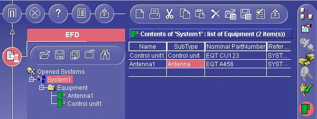
11 Creating a Control Unit and an Antenna This task shows you how to create two items of equipment: a control unit and an antenna. 1. If not already current, select the system you just created in the tree view. 2. Click the Equipment icon. The BOM view for equipment appears to the right of the tree view. 3. Select the cell in the Name column and enter Control unit1. 4. Select the cell in the Sub_Type column and enter Control unit 5. Select the cell in the Nominal_Part_Num column and enter EQT CU In the second row, click the cell in the Name column and enter Antenna1. 7. Enter attributes Antenna for Sub_Type and EQT A456 for Nominal_Part_Num. 8. Click OK to validate entries made. The control unit and antenna are created and are added to the tree view in a folder named Equipment.
12

13 Creating Equipment Connectors This task shows you how to create the connectors associated with the equipment you have just defined. The logical connection between the two items of equipment will be made at connector level. 1. Select Antenna1 in the tree view. 2. Click the Connectors icon in the Functional Components toolbar. The BOM view for connectors is displayed to the right of the tree view. 3. Click the cell in the Name column and enter P7. 4. Enter an Id Number for the connector, for example Click OK to validate the entry. Connector P7 is created and identified in the tree view. 6. Select Control unit1 in the tree view. 7. Click the Connectors icon in the Functional Components toolbar. 8. Click the cell in the Name column and enter P6. 9. Enter an Id Number for the connector, for example Click OK to validate the entry. Connector P6 is created and identified in the tree view.

14 Creating the Transmit/Receive Signal This task shows you how to create the transmit/receive signal under System1. 1. Select System1 in the tree view. 2. Click the Signals icon. The BOM view for signals is displayed to the right of the tree view. 3. Select Video from the drop-down list to identify the signal type. 4. Click the cell in the Name column and enter Transmit/receive. 5. Click OK to validate the entry. The signal is created and added to the tree view. Signals are grouped in a signal folder.

15 Connecting the Control Unit to the Antenna This task shows you how to assign the transmit/receive signal to control unit and antenna connectors. 1. Select the Transmit/receive signal you just created in the tree view. 2. Click the Assign View icon. The Assign view is displayed to the right of the tree view. 3. Click on the small + sign to the left of items in the Assign view to expand them and show their contents. 4. Select connector P7 and control-click connector P6 in the top part of the Assign view. 5. Click Add to connect the control unit and antenna via the Transmit/receive signal. The connection is made and displayed in the bottom part of the Assign view. 6. Click OK in the Assign view to validate the connection. The connection is made and two end points are created under the signal.
16
17 Saving Your System This task shows you how to save the system you have just defined. 1. Select System1 in the tree view: Note: A yellow star appears in the tree view beside systems that have been modified and require saving. 2. Click the Save System icon. The Enter the CATProduct filename... dialog box appears. 3. Specify the location where you want to save your system. 4. Enter the name of the system. 5. Click Save. System1 has been saved 6. Click OK in the Information dialog box
18 Basic Tasks Installing Electrical System Functional Definition Starting Electrical System Functional Definition Creating, Opening & Saving Systems Creating Components Navigating, Editing, Moving, Deleting Electrical Connections

19 Installing Electrical System Functional Definition Electrical System Functional Definition (EFD) is a Java application integrated into the ENOVIA 3d com Navigator that resides on a network comprising the CATIA V5 server with a CORBA object distributed architecture. An Orbix server implements communication protocols for this architecture. It awaits incoming requests for server activations and connects clients to server processes. This task explains how to install Electrical System Functional Definition. You will: Install CATIA V5 (includes install of EFD and Orbix) Note: All products are installed on the same machine. Install EFD software (Java application and virtual machine) on a separate machine.
20 Hard- and software requirements are specified in the CATIA Infrastructure User's Guide. In addition, the Java virtual machine and standard Java libraries (J.D.K.) must meet the following requirement: J.D.K or higher. On Windows, the Java virtual machine provided with JDK from IBM is recommended. On UNIX, the Java virtual machine provided with JDK or from Sun Microsystems is recommended. 1. Install CATIA V5 on a UNIX workstation. For information on how to do so, see the Getting Started section in the CATIA Infrastructure User's Guide. Do not forget to activate the option restarting the Orbix daemon after a reboot. Default UNIX installation location The CATIA V5 software is installed (if you used the default location) in the directory /usr/dassaultsystemes/b04/os_a where OS_a is: aix_a hpux_a irix_a solaris_a. Electrical System Functional Definition software is installed in the install directory under /docs at the same time as the CATIA V5 software. You can however, install the Java application and virtual machine on a different machine. 2. Run CATIA Version 5 and activate the EF2 product license. This must be done by the superuser (root) and all EFD users. 3. To install Electrical System Functional Definition software on a different machine, copy all the files from installation_location/docs into a Windows folder or UNIX directory.
21 Java Environment The EFD startup shell named: run_efd.sh (UNIX) is located in directory installation_location/docs run_efd.bat (Windows) is located in folder installation_location\docs. This startup shell invokes the Java virtual machine. The path of this machine and appropriate libraries (J.D.K.) is defined by environment variable $JAVA_HOME, for example: export JAVA_HOME = /usr/jdk116 (UNIX) set JAVA_HOME = c:\jdk116 (Windows)

22 Starting Electrical System Functional Definition This task explains how to start the default Electrical System Functional Definition (EFD) Version 5 environment on Windows and on UNIX. Note: EFD is integrated into the ENOVIA 3d com Navigator. 1. Change to the directory or folder default_installation_location/docs containing the EFD startup shell. 2. Enter the command: On Windows, runefd.bat with arguments: location of EFD runtime libraries (for example, c:\program Files\Dassault Systemes\B04) location of JDK (for example, c:\jdk1.1.6). On UNIX, runefd.sh with arguments: name_of_orbix_server location of EFD runtime libraries (for example, default_installation_location/docs/java). The Portal Logon dialog box is displayed. 3. Enter the UNIX or Windows username and password, then click Logon. An Electrical System Functional Definition document is displayed. The tree view is shown to the left. Note: EFD is integrated into the ENOVIA 3d com Navigator.
23 For more information on installing Electrical System Functional Definition.
24 Creating, Opening & Saving Systems You can create new systems or open existing systems. Systems are saved as CATProduct files with one system per file. A system is an electric unit which accomplishes a specific function, for example an airplane radar system. You can define system: Equipment Connectors Signals A yellow star appears in the tree view beside systems that have been modified and require saving. This includes new systems. Create new systems: Click the New System icon and enter a name in the dialog box, then click OK. Open existing systems: Click the Open System icon and double-click the desired system in the dialog box. Close systems: Select a system in the tree view then click the Close System icon. Save systems: Select a system in the tree view then click the Save System icon. Save all systems: Click the Save All Systems icon.
25 This task explains how to create a new system. Creating New Systems 1. Click the New System icon. The New system... dialog box appears. 2. Enter the name of the system you want to create in the dialog box, then validate by pressing Enter or clicking OK. The new system is created in the server data model and is represented in the tree view. The BOM view of the new system is shown to the right in the document window. The current object is identified in the BOM view.
26 3. Enter attributes identifying your system in the BOM view. 4. Click OK to validate entries made. You can now define system equipment, connectors and signals as desired. You can create more than one system in any one Electrical System Functional Definition document. When you save the document, each system will be saved in a separate CATProduct file.

27 Opening Existing Systems This task explains how to open existing systems saved as CATProduct type files. 1. Click the Open System icon. The Select a CATProduct file... dialog box appears. 2. Specify the location of the system to be opened. 3. Double-click the system of interest Or, Click the system of interest, then click the View icon in the dialog box. Or, Click the system of interest, then click Load. Or, Enter the name of the CATProduct directly in the field at the bottom of the dialog box, then click Load. Note: Multiple selection using ctrl-clicking or shift-clicking is available. The system is displayed. Note: You can open more than one system in any one EFD document.

28 If the system opened contains links to systems in other documents, a Links to systems folder appears in the webtree. Opening documents in this folder resolves the links in your EFD session.

29 Closing Systems This task explains how to close a system. 1. Select the system you want to close in the tree view. 2. Select the Close System icon. If changes have been made since the last save, a message to this effect is displayed. 3. Specify whether or not you want to save the system.

30 Saving Systems Systems are saved in CATProduct type files with one system per file. This tasks explains how to save a system in a CATProduct type file. 1. Select the system you want to save in the tree view. 2. Click the Save System icon. The Enter the CATProduct Filename... dialog box appears. 3. Specify the location of the system to be saved. 4. Enter the name of the system. 5. Click Save. Note: If the CATProduct file already exists, a Warning panel asking you if you want to replace the existing CATProduct file appears. A message indicating that the current system has been saved is displayed.
31 Saving All Systems Systems are saved in CATProduct type files with one system per file. This tasks explains how to save all the systems you have opened. 1. Click the Save All Systems icon. The Enter the CATProduct Filename... dialog box appears ready for you to save the first system never saved before. If opened systems have already been saved, then the dialog box does not appear and systems are saved under the name given the first time they were saved. 2. Specify the location of the system to be saved. 3. Enter the name of the system. 4. Click Save. The Enter the CATProduct Filename... dialog box appears again. 5. Repeat the above until all systems have been saved. A message indicating that all systems have been saved is displayed.
 and attributes of equipment to create in the BOM view and click OK.")
32 Creating Functional Electrical Components Having created a system, you are now ready to define the components making up this system. Create equipment: Select a system, click the Equipment icon then enter the name(s) and attributes of equipment to create in the BOM view and click OK. Create connectors: Select an item of equipment or a system, click the Connector icon then enter the name(s) and attributes of connector(s) to create in the BOM view and click OK. Create contact points: Select an item of equipment or a connector, click the Contact Point icon then enter the name(s) and attributes of contact point(s) to create in the BOM view and click OK. Create signals: Select a system, click the Signal icon and select the signal type, then enter the name(s) and attributes of signal(s) to create in the BOM view and click OK. Copy & paste components: Select the item to copy, click the Copy icon then select the target parent component and click the Paste icon. Create offsheet connectors: Select a signal, click the Offsheet Connector icon, then enter the name(s) and attributes of offsheet connector(s) in the BOM view and click OK. The tasks in this section step you through the creation of some of the functional electrical components shown on the schematics diagram below:

33 Validating information means that the data is sent to the server. If knowledgeware is used, the server checks data received and if necessary, corrects it then sends the updated view back to the client. In BOM views, information is validated when you click OK, when you change the current object in the tree view or when you change the active view. A yellow star appears in the tree view beside systems that have been modified and require saving.
34 Creating Equipment A piece of equipment is a functional electrical device with one or more associated connectors, for example a lamp or a battery. Equipment is created directly under the system. This task explains how to create equipment. In this example, you will create headphone1, microphone1, control unit1, control panel1 and power panel1. You have created a new system or opened an existing system. 1. If not already current, select the system for which you want to define equipment in the tree view. Note: Available commands are highlighted in the Functional Components toolbar. 2. Click the Equipment icon. The BOM view for equipment appears to the right of the tree view. 3. Click the cell in the Name column and give the equipment a meaningful name, for example headphone1. 4. (Optional) Click cells in attribute columns and complete with appropriate values. 5. Continue to identify the equipment you want to associate with the system by filling in one row per piece of equipment. Note: Right-click in the BOM view and select Insert Rows to automatically create entries below existing entries, then define the number of rows in the dialog box that appears. The name attribute is automatically valuated and incremented.

35 Use the Special Paste command in the contextual menu to use data from other applications, for example Excel files, in Electrical System Functional Definition. You can copy entire rows in BOM views into other applications or into the BOM view to create new entries. Right-click a cell in the row you want to copy and select Select Row from the contextual menu. The entire row is highlighted. Right-click again and select Copy. To modify an item, simply double-click it and position cursor as desired. You can sort items in BOM view columns in ascending alphabetical order (first click), descending alphabetical order (second click) and initial order (third click). 6. Click OK to validate entries made. The reference designator attribute is automatically valuated if no value was entered. New equipment is created and is added to the tree view. Equipment is grouped in an Equipment folder. You can view the properties of and components connected to the current component via the Properties command in the tree view contextual menu.

36 Creating Connectors A connector is a functional electrical component with one or more associated contact points, for example, a power or signal transmission connector. Connectors can be created directly under the system and under equipment. This task explains how to associate connectors to equipment. In this example, you will create the three connectors for the control unit. Open the CreateConnectors.CATProduct document from the samples folder. 1. In the tree view, select the item of equipment to which you want to associate connectors, Or, Select the system if you want to create connectors directly under it. 2. Click the Connectors icon in the Functional Components toolbar. The BOM view for connectors is displayed to the right of the tree view. 3. Click the cell in the Name column and give the connector a meaningful name. 4. Click the cell in the Id Number column and enter a number. Note: This attribute is compulsory. Id Numbers of connectors under any one item of equipment or system must be unique. These numbers are used to map functional components and corresponding physical parts. 5. (Optional) Click other cells in attribute columns and complete with appropriate values. 6. Continue to identify the connectors you want to associate with the equipment by filling in one row per connector. Note: Right-click in the BOM view and select Insert Rows to automatically create entries below existing entries, then define the number of rows in the dialog box that appears. The name attribute is automatically valuated and incremented.

37 Use the Special Paste command in the contextual menu to use data from other applications, for example Excel files, in Electrical System Functional Definition. You can copy entire rows in BOM views into other applications or into the BOM view to create new entries. Right-click a cell in the row you want to copy and select Select Row from the contextual menu. The entire row is highlighted. Right-click again and select Copy. To modify an item, simply double-click it and position cursor as desired. You can sort items in BOM view columns in ascending alphabetical order (first click), descending alphabetical order (second click) and initial order (third click). 7. Click OK to validate entries made. Id number and reference designator attributes are automatically valuated if no values were entered. New connectors are created and are added to the tree view. If created directly under the system, connectors are grouped in a Connectors folder. You can view the properties of and components connected to the current component via the Properties command in the tree view contextual menu.
38 Creating Contact Points A contact point defines the point of contact or attachment for an electrical signal. Contact points are associated with equipment or connectors. This task explains how to create contact points. In this example, you will create contact points for control unit connector P8. Open the CreateContactPoints.CATProduct document from the samples folder. 1. Click the piece of equipment or connector to which you want to add contact points in the tree view. 2. Click the Contact Points icon in the Functional Components toolbar. The BOM view for contact points is displayed to the right of the tree view. 3. Click the cell in the Name column and give the contact point a meaningful name. 4. Click the cell in the Id Number column and enter a number. Note: This attribute is compulsory. Id Numbers of contact points under any one piece of equipment or connector must be unique. These numbers are used to map functional components and corresponding physical parts. 5. (Optional) Click cells in attribute columns and complete with appropriate values. 6. Continue to identify the contact points you want to associate with the connector by filling in one row per contact point.


39 Note: Right-click in the BOM view and select Insert Rows to automatically create entries below existing entries, then define the number of rows in the dialog box that appears. The name attribute is automatically valuated and incremented. Use the Special Paste command in the contextual menu to use data from other applications, for example Excel files, in Electrical System Functional Definition. You can copy entire rows in BOM views into other applications or into the BOM view to create new entries. Right-click a cell in the row you want to copy and select Select Row from the contextual menu. The entire row is highlighted. Right-click again and select Copy. To modify an item, simply double-click it and position cursor as desired. You can sort items in BOM view columns in ascending alphabetical order (first click), descending alphabetical order (second click) and initial order (third click). 7. Click OK to validate entries made. Id number and reference designator attributes are automatically valuated if no values were entered. New contact points are created and are added to the tree view. You can view the properties of and components connected to the current component via the Properties command in the tree view contextual menu.
40
. Signals can be created directly under the system or under a group of signals.")
41 Creating Signals A signal is a logical connection between two or more components. May be of the following types: ground, shielding, video, power, command. You can group signals you want to route together. To do so, you must first create the group (Grouped signal type). Signals can be created directly under the system or under a group of signals. This task explains how to create signals under the system or under a group of signals. In this example, you will create the control unit ground and the 28 V power signals under the system. Open the CreateSignals.CATProduct document from the samples folder. 1. Click the system to which you want to add signals in the tree view. 2. Click the Signals icon in the Functional Components toolbar. The BOM view for signals is displayed to the right of the tree view. 3. Select the type of signal, or Grouped electrical signal if you want to create a group of signals, from the Signal scroll list. 4. Click the cell in the Name column and give the signal a meaningful name.

42 5. (Optional) Click cells in attribute columns and complete with appropriate values. 6. Continue to identify the signals you want to associate with the system by filling in one row per signal Note: You can also select other types and add signals of selected types to the system. Use the Special Paste command in the contextual menu to use data from other applications, for example Excel files, in Electrical System Functional Definition. You can copy entire rows in BOM views into other applications or into the BOM view to create new entries. Right-click a cell in the row you want to copy and select Select Row from the contextual menu. The entire row is highlighted. Right-click again and select Copy. To modify an item, simply double-click it and position cursor as desired. You can sort items in BOM view columns in ascending alphabetical order (first click), descending alphabetical order (second click) and initial order (third click). 7. Click OK to validate entries made. New signals are created and are added to the tree view in a dedicated Signal folder. You can view the properties of and components connected to the current component via the Properties command in the tree view contextual menu.
43


44 Creating Components using Copy & Paste You can create individual components, sub-systems and entire systems in the tree view using copy and paste commands. The copy command copies the selected items to the clipboard. The paste command pastes the contents of the clipboard to the tree view. This task explains how to create electrical components using copy and paste commands. Open the CopyPaste.CATProduct document from the samples folder. 1. Select the electrical component you want to copy in the tree view. 2. To copy, you can either: click the Copy icon, or select Copy from the contextual menu. The selected component along with any children is copied to the clipboard. Note: Connections are not copied. They must, if necessary, be made when the component is pasted to its new location. 3. Select the parent component to select the destination for the component you want to copy. 4. To paste, you can either: click the Paste icon, or select Paste from the contextual menu. The selected component along with any children is pasted to the new location in the tree view.
45 If there is a naming conflict, the name of the copied component is changed. A message informs you if the selected component is incompatible and cannot be created under the current object. There is no need to validate copy and paste operations, since validation is automatic when you work directly in the tree view. You can view the properties of components connected to the current component via the Properties command in the tree view contextual menu.

46 Creating Offsheet Connectors Offsheet connectors enable you to place markers in your functional definition that are used to establish connections between different systems. They are created under signals. This task explains how to create offsheet connectors. Open the CreateOffsheetConnectors.CATProduct document from the samples folder. 1. Click the signal to which you want to add an offsheet connector in the tree view. 2. Click the Offsheet Connector icon in the Functional Components toolbar: The BOM view for offsheet connectors is displayed to the right of the tree view. 3. Click the cell in the Name column and give the offsheet connector a meaningful name. 4. (Optional) Click cells in attribute columns and complete with appropriate values. If needed, you can create offsheet connectors of different types for the same signal. 5. Click OK to validate the entry made. The offsheet connector is created and is identified in the tree view under the signal. To be able to establish offsheet connections: Signals must be of the same type Offsheet connector names must be identical. Note: Additional rules can be programmed.
47 Navigating, Editing, Moving & Deleting Electrical Components This section describes a number of other operations you can perform in the EFD workbench. Generate a graphical preview: Click the 2D Preview icon. Find components: Click the Find icon, enter a string in the Find dialog box and click Find Next. Jump to connected objects: Right-click a component and select Go to..., select a connected object then click Go to the selected object. Edit attributes in the properties view: Select a component and click the Properties icon, then make desired changes in the properties view and click OK. Edit attributes in the BOM view: Select the parent component and click the appropriate component icon, then make desired changes in the BOM view and click OK. Edit component properties: Right-click a component and select Properties. Browse signal end point attributes: Select a signal and click the Signal End Point icon. Move components using cut & paste: Select a component, click the Cut icon, then select the target parent component and click the Paste icon. Delete components: Select a component and click the Delete icon.
 opened. A 2D preview is displayed to the right in the document window.")
48 Generating a Graphical Preview This task explains how to preview opened systems. Open the GraphicalPreview.CATProduct document from the samples folder. 1. Click the 2D Preview icon then Redraw to generate a graphical preview of system(s) opened. A 2D preview is displayed to the right in the document window. To automatically refresh the preview, check the Automatic redraw option in the General tab of the Options dialog box. This tab also lets you align equipment horizontally or vertically in the preview. A slider at the bottom of your document lets you zoom in and out of your preview. Contextual menu commands are available in the 2D preview. As you move the cursor over items, components are highlighted and the name and type are displayed. This dynamic highlighting helps you visualize connections easier.
49

50 Finding Components This task explains how to search for electrical components in the tree view. 1. Click an item in the tree view, then click the Find... icon. The Find... dialog box appears 2. Enter a string to search for the component you want to find in the Text to find field. 3. Click the Up or Down radio button to search for the component from your current position to the top or bottom of the tree view. 4. Check the Match case option if you want to search to be case-sensitive. 5. Click Find Next to start the search. If found, the component is highlighted in the tree view and the Properties view for the component displayed. If no matching text is found, a message to that effect is displayed.

51 Jumping to Connected Objects This task explains how to jump to connected objects. Open the JumpTo.CATProduct document from the samples folder. 1. Right click an item in the tree view and select Go to... from the contextual menu. The Properties dialog box appears. The Connected objects tab is active and lists objects connected to the current object. 2. Select an item in the list. 3. Click Go to the Selected Object to jump to the item in question. The selected object becomes the current object and is highlighted in the tree view 4. Click Cancel to exit the dialog box. Connected objects, if any, can also be viewed when you access object properties via the Properties command in the contextual menu.
52

53 Editing Component Attributes in the Properties View This task explains how to edit the attributes of an electrical component in the Properties view. Open the Modify.CATProduct document from the samples folder. 1. Click the electrical component whose attributes you want to edit in the tree view. 2. If necessary, click the Properties icon in the Workshop Commands toolbar: The Properties view for the selected component is displayed to the right of the tree view. 3. Make desired changes to attribute values. 4. Click OK to validate changes made. In the Properties view, information is validated when you click [OK], when you change the current object in the tree view or when you change the active view. You can rename components in the Properties view. Simply click the Name data field and enter a new name, then press Enter to validate.
54

55 Editing Attributes of Several Components in the BOM View This task explains how to edit the attributes of several different electrical components in the BOM view. Open the Modify.CATProduct document from the samples folder. 1. Click the parent of the electrical components whose attributes you want to edit. 2. Click the appropriate icon in the right toolbar, for example Equipment to edit attributes of items of equipment. The BOM view for equipment is displayed. Each row corresponds to an item of equipment. 3. Make desired changes to attribute values. Note: You can also fill in new rows to create new items of equipment. 4. Click OK to validate changes made.

56 Editing Component Properties This task explains how to view and edit the properties of a component. Open the Modify.CATProduct document from the samples folder. 1. Right click an item in the tree view and select Properties from the contextual menu. The Properties dialog box listing the attributes and attribute values of the selected component appears. 2. Edit the object name and/or attribute values as desired. 3. Click Ok when done. Connected objects, if any, can also be viewed when you access component properties via the Properties command in the contextual menu.
57 Browsing Signal End Point Attributes A signal can have two or more end points. End points are used to manage the connection between signals and electrical components. End points are automatically created when you connect functional electrical components. They are identified Ext.name_of_connected_component in the tree view. This task explains how to browse and modify signal end point attributes. 1. Select the signal whose end point attributes you want to browse in the tree view. 2. Click the Signal End Points icon in the Functional Components toolbar: The BOM view for signal end points is displayed to the right of the tree view. 3. Edit the name and/or enter the attributes of the signal end point. 4. Click OK to validate entries made.


58 Moving Electrical Components Using Cut & Paste You can move individual components, sub-systems or entire systems re-arranging them in the tree view using cut and paste commands. The cut command removes the selected items and places it on the clipboard. The paste command pastes the contents of the clipboard to the tree view. This task explains how to move electrical components using cut and paste commands. 1 Select the electrical component you want to move in the tree view. 2. To cut, you can either: click the Cut icon, or select Cut from the contextual menu: The selected component along with any children is copied to the clipboard and the component deleted from the system. Connections are not copied. They must, if necessary, be re-made when the component is pasted to its new location. 3. Select the parent component to select the destination for the component you want to move. 4. To paste, you can either: click the Paste icon, or select Paste from the contextual menu: The selected component along with any children is moved to the new location in the tree view. A message informs you if the selected component is incompatible and cannot be created under the current object.
59 There is no need to validate cut and paste operations, since validation is automatic when you work directly in the tree view.

60 Deleting Electrical Components This task explains how to delete electrical components. 1. Select the electrical component you want to delete in the tree view. 2. To delete, you can either: click the Delete icon, or select Delete from the contextual menu. 3. Click OK in the Warning dialog box to confirm you want to delete the selected component. The component is deleted along with any children. Any connections to deleted components are also deleted. There is no need to validate delete operations since validation is automatic when you work directly on the tree view.
 or, components to signals. External connections are made by means of offsheet connectors.")

61 Electrical Connections You can establish both internal and external system connections. Internal connections are made by assigning signals to components (equipment, connectors and contact points) or, components to signals. External connections are made by means of offsheet connectors. Signal end points identifying connected components are automatically created when connections are established. Connect signals to components: Select a component, click the Assign View icon, then select the signal to be assigned and click Add then OK. Connect components to signals: Select a signal, click the Assign View icon, then select a component, click Add then OK. Check connections: Browse connection flags displayed on connected components in the tree view. Fine-tune connections: Select a component or signal, click the Refine View icon, then select the connection to fine-tune, double-click the downstream component to which you want the connection moved and click OK.> Making offsheet connections: Create a new system, click the Resolve Links View icon, then select an unresolved offsheet connector followed by a compatible offsheet connector and click Resolve. Analyze system connections: Select a system then click the Analyze Links View icon.

62 Assigning Signals to Equipment, Connectors & Contact Points This task explains how to assign signals to equipment, connectors and contact points. In this example, you will assign the control unit ground signal to contact point P8-6. Open the AssignSignals.CATProduct document from the samples folder. 1. Select the equipment, connector or contact point to which you want to assign one or more signals in the tree view. The selected electrical component becomes the current object. 2. Click the Assign View icon in the Workshop Commands toolbar. The Assign View is displayed. This view lets you assign signals to equipment, connector and contact points. 3. Expand the tree to see the various system signals in the top half of the view. 4. Select the signal(s) you want to assign to the current object. Notes: Ctrl-click signals to select more than one signal. Assigning a group signal assigns all the signals in the group to the current component. 5. Click Add. Selected signals are added to the list of connections. Note: The entire path down to the selected component is identified in the list of connections.
63 6. Click OK to validate entries made. Connections are made and an end point is created under each connected signal. In Assign views, information is validated when you click OK in the Assign view, when you change the current object in the tree view or when you change the active view.
64 Assigning Equipment, Connectors & Contact Points to Signals This task explains how to assign equipment, connectors and contact points to signals. In this example, you will assign contact point P8-5 and connector PWR1-1 to the 28 V power signal. Open the AssignSignals.CATProduct document from the samples folder. 1. Select the signal to which you want to assign one or more electrical components in the tree view. The selected signal becomes the current object. 2. Click the Assign View icon in the Workshop Commands toolbar. The Assign View allowing you to assign equipment, connector and contact points to signals is displayed. 3. Expand the tree to see the various electrical components that can be connected in the top half of the view. 4. Select the equipment, connector(s) or contact point(s) you want to assign to the current object. Notes: Ctrl-click components to select more than one. Assigning a component to a group signal assigns the component to all the signals in the group. 5. Click Add. Selected components are added to the list of connections. Note: The entire path down to the selected component is identified in the list of connections. 6. Click OK to validate entries made. Connections are made and an end point is created under each connected signal.
65 In Assign views, information is validated when you click [OK] in the Assign view, when you change the current object in the tree view or when you change the active view.

66 Connection Flags This task shows how to rapidly identify where connections can still be made or where fine-tuning is required. This will help you, for example, to optimize the correspondence between the number of contact points and the number of connections to be made. 1. Browse component connections in the tree view. Different types of connection flag are displayed on connected components in the tree view: means that less than half the contact points under a given component have been connected. means that more than half the contact points under a given component have been connected. means that all contact points have been connected. No further connections can be made. identifies where the fine-tuning is required. Note: Connections are considered properly made when the connection is established from the contact point. 2. Make further connections as required (signal to component or component to signal) or fine-tune existing connections. 3. To analyze all connections of the current system, click the Analyze Links View icon in the Workshop Commands toolbar.
67 Fine-tuning Connections This task explains how to refine connections, moving them to other points within the same item of equipment. In this example, you will move the connection from a connector down to a contact point. Connections are considered properly made when the connection is established from the contact point. 1. Select the electrical component or the signal whose connections you want to refine in the tree view, for example connector P8. 2. Click the Refine View icon in the Workshop Commands toolbar. The Refine View shows all connections established for the current object. 3. In the Refine view, select the connection you want to modify, for example the 28 V power connection. Components making up the equipment at which the connection is made are displayed in the bottom half of the window. 4. In the bottom half of the window, select the component at which you want the connection made, for example contact point P8-5: Double-click the component, or Click the component and then click Refine Connections. The path in the top half of the window is updated.
68 5. Click OK to validate the modification.

69 Making Offsheet Connections Offsheet connectors enable you to place markers in your functional definition and are used to establish connections between different systems. They are created under signals and can be connected either automatically or manually. Offsheet connections can be made in a dedicated system, and not in the systems containing the connectors themselves. To be able to establish offsheet connections: Signals must be of the same type Offsheet connector names must be identical. This task explains how to make offsheet connections. You must have a minimum of two systems with offsheet connectors already created. 1. Select an existing system in the tree view if you want to add new connections to an existing system Or, Click the New System icon in the Standard toolbar to create a new system. 2. Click the Resolve Links View icon in the Workshop Commands toolbar: Note: Any connections made are done in the current system. The Resolve Links view is displayed to the right of the tree view. The top part lists offsheet connectors for which no connection has been made. Note: Offsheet connectors associated with more than one component are only listed once.

70 3. Make offsheet connections:. Click Automatic Resolution to have the application automatically make them, b. Or, To make the connection manually: Select an unresolved offsheet connector: Compatible offsheet connectors which have not yet been connected are displayed in the middle part of the view and those which have already been connected but to which you can add connections are displayed in the bottom part of the view. Select a compatible offsheet connector. To be able to establish offsheet connections, signals must be of the same type and connector names must be identical. Click Resolve The connection is added to the current system in the tree view. Note that the symbol identifying the offsheet connection signal differs from those used for other types of signal. All components assigned to signal offsheet connectors are also identified in the tree view.
71

72 Analyzing System Connections This task explains how to analyze internal and external connections of the current system. 1. Select the system you want to analyze in the tree view 2. Click the Analyze Links View icon in the Workshop Commands toolbar This command gives an overall view of current system connections. By default, only external connections are shown. 3. To display all connections, uncheck the Only external connections checkbox. 4. To delete a connection, select the desired connection, then Remove Connections. 5. Click OK to validate any changes made or Cancel to undo.
73 Advanced Tasks Using Data from Other Applications Printing System Information Importing & Exporting Systems Interoperability with Electrical Library Interoperability with ENOVIA V5 VPM1 Interoperability

74 Using Data from Other Applications in BOM Views You can use other applications to generate data that you can then paste in Electrical System Functional Definition BOM views. For example, you can prepare an Excel spreadsheet with the various attributes of an electrical component. This task explains how to use data prepared in an Excel spreadsheet in BOM views. 1. Ensure that the Excel spreadsheet is properly prepared: The first row identifies component attributes. Other rows give values for attributes with one row per component. Attributes can be listed in any order. You do not need to identify all the attributes associated with any one component. 2. In the Excel spreadsheet, select everything you want to copy, including the headings then select Copy from the contextual menu 3. In the appropriate BOM view of the Electrical System Functional Definition application, right-click and select Special Paste from the contextual menu. Data generated in the Excel spreadsheet is pasted to the BOM view and sorted into appropriate columns. You can do a simple copy and paste of cells containing the data you want to add. You can copy and paste cell data within the BOM view as well as copy data from Electrical System Functional Definition into other applications, for example Excel spreadsheets. The Select Row command in the contextual menu lets you copy entire rows: right-click a cell in the row you want to copy and select Select Rows from the contextual menu (the entire row is highlighted), right- click again and select Copy.
75

76 Printing System Information This task explains how to print system information. Data can be routed directly to a printer or printed to a file. 1. Click the Print icon. The Print dialog box appears. 2. Using the Select system drop-down list, select the system whose information you want to have printed 3. Identify the information you want printed: By default, system data about components including signals, and component properties is printed. De-activate options if associated data is not desired. 4. Click Print. The standard Windows Print dialog box displays. 5. Select a printer or check the Print to file check box. 6. If you checked Print to file, then enter the name of the output file and click OK in the Print to File dialog box, Or, If you selected a printer, set the Page range and number of Copies then OK in the Print dialog box. Print options (paper margins, etc.) can be set in the ElecAppli.properties file.
77 Importing & Exporting Systems About neutral files: Gives information on how to prepare neutral files. Import systems & connections: Prepare a neutral file, then click the Import System icon. Select the neutral file and click Import. Export systems: Select a system and click the Export System icon.
78 About Neutral Files The neutral file format lets you import and export electrical system functional definitions. Internal and external system connections are managed at the same time as the description of the system itself. Neutral files are text files and can therefore be created using a simple text editor. The advantage of using neutral files is that you can import and export onto any platform. Two different neutral file formats can be used: CSV (comma delimited)-like format EFD format CSV-like Format One or more electrical systems can be described in any one file. Applications such as Microsoft Excel can be used to generate your neutral file (save as *csv). These files can then be imported directly into Electrical System Functional Definition (EFD). Example: ElecFnctEqt;Name;Ref_Des;User_Desc;Nominal_Part_Num;CsvID;FatherID ElecFnctEqt;Battery;;;Part_XX1;3;1 ElecFnctEqt;Ventilator;;;Part_YY2;4;2 ElecConnection;SignalExtID;ExternalSignalExt;TargetID;ExternalTarget ElecConnection;8;;4; ElecConnection;9;;;Cooler System ElecFnctCntPt ((Name power)) ElecConnection;10;;5; ElecConnection;11;;;Cooler System ElecFnctCntPt ((Name ground)) Rules CSV-like neutral files must comply with the following rules: Information is grouped by electrical type. Only electrical types known by EFD can be described. Types are identified by the internal or long name. Note: There is no required order when describing types. The first row (header) defines the type and identifies attributes and assembly relationships. Attributes, apart from the electrical type which always comes first, can be listed in any order and you do not need to identify all electrical type attributes. The following, however, must appear: CsvID: a unique identifier in any one neutral file used to identify components. Name: the name of the component.
79 FatherID: identifies the parent component. This attributes takes the value of the CsvID of the parent component. For root components, such as electrical systems, this attribute has no value. The next rows describe one component each and list the name, attribute values and assembly relationships. Columns having no values must remain empty. If more than one system is described, each description must begin with the identification of the system in question. Connections are described by two items: a signal end point and an equipment, connector or contact point. For internal connections, the CsvID of both items must be given as the value of attributes SignalExtID and TargetID. Example: ElecConnection;SignalExtID;ExternalSignalExt;TargetID;ExternalTarget ElecConnection;8;;4; External connections are identified by the target system name followed by a pipe ( ), the target component electrical type, a pipe ( ), the list of target component attributes ((Attribute1Name Attribute1Value)(Attribute2Name Attribute2Value) etc.). Example: ElecConnection;SignalExtID;ExternalSignalExt;TargetID;ExternalTarget ElecConnection;9;;;Cooler System ElecFnctCntPt ((Name power)) EFD Format Only one electrical system can be described per neutral file. Example: Electrical Functional Connector ID Name Nominal_Part_Number Id_Number Father Child0 Child1 Connection0 # 3 P8 875b47 Electrical Functional Equipment:Control unit Contact Point:P8-5 Contact Point:P8-6 Electrical Power Signal:28 V \ Electrical Functional Equipment ID Name Sub_Type Nominal_Part_Number Father Child0 Child1 Child2 Connection0 Connection1 # 1 Control unit1 Control unit B47-5 Electrical System:1 Electrical Functional Connector:P5 Electrical Functional Connector:P6 Electrical Functional Connector:P8 Contact Point:P8-5 Contact Point:P8-6 where: is the column separator ( identifies an empty column) # is the line separator \ is the electrical type separator
80 Rules EFD neutral files must comply with the following rules: Information is grouped by electrical type (connector, equipment, etc.). Note: There is no required order when describing types. The first row (header) identifies the component (ID), component attributes (name, Nominal_Part_Number, etc.), the link to the parent (Father), links to children (Child0, Child1, etc.) and connections to other components (Connection0, Connection1, etc.), and must be described in this order. The component ID identifies each instance of the electrical type and is a unique identifier. Component attributes can be listed in any order. You do not need to identify all the attributes associated with any one component. Internal connections must be written as follows: Electrical_type:name_of_linked_component Columns having no values must remain empty. External connections are identified as follows: Target system name followed by a semicolon (:), the target component class, a semicolon (:), the list of target component attributes ((Attribute1Name:Attribute1Value)(Attribute2Name:Attribute2Value) etc.). Example: Electrical Signal End Point Name Shielded Father Child0 Connection0 # EndPointEqt3 Electrical Power Signal:2 system2:electrical Functional Equipment:((Name:eqt3))


81 Importing Systems & Inter-System Connections from Other Applications You can import systems from other applications via a neutral file into Electrical System Functional Definition. Connections between the system you want to import and other systems are also managed. Neutral files can be written directly, or you can also use other applications, for example an Excel spreadsheet, to generate data which you then save in neutral file format. This task explains how to import systems into the Electrical System Functional Definition application. In this example, you will import a system from an Excel file. The import will be done in two steps: Preparing the Excel file and saving it in the CSV (comma delimited) format Importing data into Electrical System Functional Definition. 1. Ensure that the Excel file is properly prepared. Note: More than one electrical system can be described in a single Excel spreadsheet.
82 Excel files saved in the CSV (*.csv) format must comply with the following rules: Information is grouped by electrical type, identified by the type internal or long name. Note: There is no required order when describing electrical types. The first row (header) defines the type and identifies attributes and assembly relationships. Attributes, apart from the electrical type which always comes first, can be listed in any order and you do not need to identify all electrical type attributes. The following, however, must appear: CsvID: a unique identifier in any one file used to identify components. Name: the name of the component. FatherID: identifies the parent component. This attributes takes the value of the CsvID of the parent component. For root components, such as electrical systems, this attribute has no value. The next rows describe one component each and give the name, attribute values and assembly relationships. Columns having no values must remain empty. Internal and external system connections must be written as follows: Internal connections: the CsvIDs of the signal end point and of the connected component must be given. External connections: Target system name followed by a pipe ( ), the target component electrical type, a pipe ( ), the list of target component attributes ((Attribute1Name Attribute1Value)(Attribute2Name Attribute2Value) etc.) If more than one system is described, each description must begin with the identification of the system in question. 2. When you have completed your Excel spreadsheet, save the file in the CSV (*.csv) type format: The neutral file is generated and ready to be imported. You can also write your neutral file directly. 3. In the Electrical System Functional Definition application, click the Import System icon. The Import System dialog box is displayed. Note: You can import in CSV (*csv) or EFD (*elec) format. 4. Select the neutral file you just generated. 5. Click Import. The selected file is analyzed and system components created. The complete system can be viewed in the tree view. 6. Select the Save System icon to save the system in a CATProduct type file.
83 Exporting Systems You can export systems in CSV (comma delimited) or EFD format. This task explains how to export systems in CSV (*csv) or EFD (*elec) format. 1. Select the system you want to export in the tree view. 2. Click the Export System icon. The Export System dialog box is displayed. 3. Specify the path of the folder in which you want to save the file. 4. Specify the name of the file in the File name field. 5. Set the file extension to *csv or *elec. 6. Click Export when done. The file is exported in the selected format.
84 Interoperability with Electrical Library Map functional components to physical parts: Right-click an item of equipment or connector and select Map Functional/Physical... from the contextual menu. Set options in the dialog box, click Search then select part. Generate functional components from physical parts: Right-click an item of equipment or connector and select Make Functional from Physical... from the contextual menu. Set options in the dialog box, click Search then select part.
85 Mapping Functional Components to Physical Parts You can map functional equipment and connectors to V4 library as well as to V5 catalog parts to prepare the physical world. Notes: Since V4 libraries are UNIX libraries, the EFD server must reside on a UNIX machine to have access to this command when mapping to V4 parts. V5 catalogs are file-type catalogs located on the EFD server irrespective of the operating system used. This task explains how to associate the physical part that will perform the function of the functional component. 1. Right-click an item of equipment or connector in the tree view. 2. Select Map Functional/Physical... from the contextual menu. The Map Functional/Physical dialog box is displayed.

86 3. Select the V4 or V5 catalog option. 4. If mapping to V4 parts, specify the catalog in the drop-down box, or if mapping to V5 parts, click... to display the Select catalog dialog box and select the catalog of interest. Note: If no V4 catalogs are available, server parameters are not correctly set. For more information, see the Electrical Library User's Guide. 5. Select the family of interest. Note: V5 catalog families can be associated to physical equipment and connector types. For information on how to do so, see the Electrical Library User's Guide. Doing so affects the families proposed in the Map Functional/Physical dialog box: If there are no settings, all V5 last-level catalog families are proposed. If all V5 catalog families are associated with a physical type, only compatible families are proposed. If some V5 catalog families are associated with a physical type but others not, compatible families as well as families with no associated physical type are proposed. There is one physical equipment type, however, several physical connector types (ground stud, terminal block, etc.) can perform the function of the one and only functional connector type. 6. Click Search for Parts. Compatible physical parts are listed in the Search Results box. 7. Enter attributes in the Search Options box then click Search for Parts again to narrow your search: The Search Results box is refreshed. 8. Select the part you want to associate to the functional component. 9. Click OK when done. The functional component is mapped to the selected V4 library or V5 catalog part. When mapping is to V4 parts, V4 Part Number, V4 Library, V4 Family and Nominal PartNumber attributes are appropriately valuated in the EFD application. When mapping is to V5 parts, the Nominal PartNumber attribute is valuated. If any V4 attributes are valuated, they are deleted since now obsolete.
87
88 Generating Functional Components from Physical Parts You can automatically generate functional components from V4 library and V5 catalog parts. This allows you to re-use existing designs and related knowledge. Notes: Since V4 libraries are UNIX libraries, the EFD server must reside on a UNIX machine to have access to this command when generating components from V4 parts. V5 catalogs are file-type catalogs located on the EFD server irrespective of the operating system used. This task explains how to create functional components from selected physical parts (equipment or connectors) or indeed how to generate an entire functional system. 1. Right-click a system or an item of equipment in the tree view. 2. Select Make Functional from Physical... from the contextual menu. The Make Functional from Physical dialog box is displayed.
89 3. Select the V4 or V5 catalog option. 4. If mapping to V4 parts, specify the catalog in the drop-down box, or if mapping to V5 parts, click... to display the Select catalog dialog box and select the catalog of interest. Note: If no V4 catalogs are available, server parameters are not correctly set. For more information, see the Electrical Library User's Guide. 5. Select the family of interest.


90 Note: V5 catalog families can be associated to physical equipment and connector types. For information on how to do so, see the Electrical Library User's Guide. Doing so affects the families proposed in the Map Functional/Physical dialog box: If there are no settings, all V5 last-level catalog families are proposed. If all V5 catalog families are associated with a physical type, only compatible families are proposed. If some V5 catalog families are associated with a physical type but others not, compatible families as well as families with no associated physical type are proposed. There is one physical equipment type, however, several physical connector types (ground stud, terminal block, etc.) can perform the function of the one and only functional connector type. 6. Click Search for Parts. Compatible physical parts are listed in the Search Results box. 7. Enter attributes in the Search Options box and click Search for Parts again to narrow your search: The Search Results box is refreshed. 8. Select the part you want to create. 9. Click OK when done. Note: If the selected V4 library or V5 catalog part is a system, the entire functional structure right down to any contact points is generated. 10. Click the Properties icon. When generating from V4, V4 Part Number, V4 Library, V4 Family attributes and Nominal PartNumber are appropriately valuated in the EFD application. When generating from V5, the Nominal PartNumber is valuated.
91
92 Interoperability with ENOVIA V5 Working with Electrical System Definition (EFD) in ENOVIA V5 is a completely distinct mode from EFD file mode (via the ENOVIA 3d com Navigator). Note: An ENOVIA license is required to use ENOVIA V5 capabilities. Opening new systems: In Product Class Editor WebSpace, right-click node under which you want to create a new system and select Send to editor -> Electrical Functional Editor from contextual menu. Select Electrical Functional Design tab in WebSpace and enter a unique name in dialog box that appears. Opening existing systems: In the Product Class Editor WebSpace, right-click the document containing the system to open and select Send to editor -> Electrical Functional Editor from contextual menu. Saving systems: Click the Save All Systems icon in EFD, then commit to the ENOVIA database.

93 Creating New Systems This task explains how to create new systems from ENOVIA V5 opening them in Electrical System Functional Definition (EFD). 1. Start ENOVIA V5. 2. In ENOVIA V5, click the EFD icon in the WebInfo area to start EFD within ENOVIA V5: An EFD document appears in the WebSpace. To ensure that EFD is available in ENOVIA V5, start EFD using the runefd.bat command once. This adds the EFD icon to your user preferences and ensures it is available in the WebInfo area. 3. Click the Product Class Editor icon in the WebInfo area 4. Right-click a product root and select the Expand -> All command from the contextual menu to expand the product class structure. 5. Right-click the node under which you want to create your new document and select Send to editor -> Electrical Functional Editor from the contextual menu. 6. Switch to the Electrical Functional Design WebSpace. The New System panel appears.

94 7. Enter a unique name for the system you want to create. 8. Click the EFD icon in the WebInfo area. You are now ready to create the components making up your system. For more information on the product class editor, see the Product Class Editor section in the appropriate Life Cycle Application user guide, for example Professional Role User's Guide.
95
96 Opening Existing Systems This task explains how to open existing systems stored in ENOVIA V5 into Electrical System Functional Definition (EFD). 1. Start ENOVIA V5. 2. In ENOVIA V5, click the EFD icon in the WebInfo area to start EFD within ENOVIA V5: An EFD document appears in the WebSpace. To ensure that EFD is available in ENOVIA V5, start EFD using the runefd.bat command once. This adds the EFD icon to your user preferences and ensures it is available in the WebInfo area. 3. Click the Product Class Editor icon in the WebInfo area 4. Right-click the product root class (prc) and select the Expand -> All command from the contextual menu to open the prc and find the document containing the system of interest. 5. In the Show document dialog box, click the All checkbox under Show. 6. Right-click the document and select Send to editor -> Electrical Functional Editor from the contextual menu. 7. Switch to the Electrical Functional Design WebSpace. The selected system is loaded.
97 8. Click the EFD icon in the WebInfo area. You can now make appropriate modifications. For more information on the product class editor, see the Product Class Editor section in the appropriate Life Cycle Application user guide, for example Professional Role User's Guide.


98 Saving Systems in ENOVIA V5 This task explains how to save systems, which you modified in EFD, in ENOVIA V5. You are working with EFD in an ENOVIA V5 environment. 1. In EFD, click the Save All Systems icon and click OK in the dialog box that appears to confirm your action. 2. Switch to the Product Editor WebSpace to check that your systems have indeed been saved. 3. Right-click the appropriate product root class and select the Expand -> All command from the contextual menu. 4. In the Show document dialog box, click the All checkbox under Show: Any new items appear and all changes are recorded. 5. Commit the changes to the ENOVIA V5 database. The Close System command also works with ENOVIA V5.
99 For more information on the product class editor, see the Product Class Editor section in the appropriate Life Cycle Application user guide, for example Professional Role User's Guide.

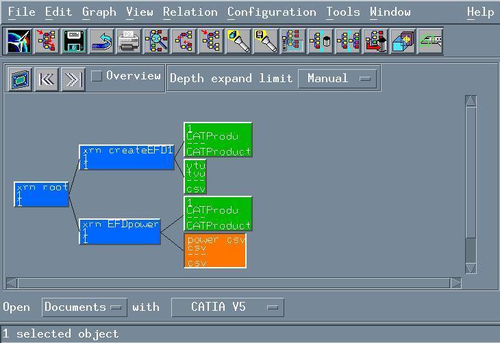
100 VPM1 Interoperability Interoperability with VPM1 is only possible if you have a CATIA-V4 Integration license and you are working on a UNIX platform. For more information about VPM1 interoperability, refer to Building a CATIA V5 Product from a VPM1 PSN Window in the CATIA-V4 Integration User's Guide. This task explains how to save EFD Version 5 data in VPM1. VPM1 and EFD (client and server) must be installed on the same machine. 1. Start VPM1. 2. Start EFD. 3. In VPM1, run the PSN on the branch where the documents of interest have been saved. 4. Expand the branch. You should obtain: 5. In this window, select the CATProduct documents to open them in EFD. An EFD session is built:


101 6. Create a signal in the EFD workbench. The signal is added to the tree view. 7. Click the Save in VPM1 icon. The corresponding CATProduct document is updated in VPM1. In addition, a new csv file is automatically generated (see Exporting Systems). The Create & Save dialog box opens in VPM1 to let you enter the information required to create the new csv document.

102 Once the new document has been created in VPM1, the PSN window looks like this:
103
104 Workbench Description The Electrical System Definition Version 5 application window looks like this: Webtree Toolbar Document Toolbar Workshop Commands & Functional Components Tree View
105 Webtree Toolbar See Opening Existing Systems See Saving Systems See Saving All Systems See Closing Systems See Finding Components
106 Document Toolbar See Creating New Systems See Printing System Information See Moving Components Using Cut & Paste See Copy & Paste See Copy & Paste and Moving Components Using Cut & Paste See Deleting Components See Importing Systems & Connections See Exporting Systems See Setting Units
107 Workshop Commands & Functional Components See Generating a Graphical Preview See Modifying Attributes in the Properties View See Assigning Signals and Assigning Equipment, Connectors & Contact Points See Connecting Floating Points See Fine-tuning Connections See Analyzing System Connections See Creating Equipment See Creating Connectors See Creating Contact Points See Creating Signals See Browsing Signal End Point Attributes See Creating Floating Points

108 Tree View Tree view icons identify EFD components and signals as follows: Systems. This icon includes a yellow star when the system is new or has been modified and requires saving. Folders. Components are grouped under Equipment and signals under Signals. Equipment. Connectors. Contact points. Command signals. Ground signals. Power signals. Shielding signals. Group of signals.
109 Video signals. Signal end points. Offsheet connectors. Offsheet connection signals. Example shown concerns an offsheet connection on a power signal.
110 Customizing Customizing Electrical System Functional Definition Setting General Preferences Setting Units

111 Customizing Electrical System Functional Definition for the Way You Work You can customize the look and feel of the Electrical System Functional Definition application to corporate practice. You can, for example, change the appearance of icons or customize toolbars and menus. Customizing is done by editing: The ElecAppli.properties file Workshop files: there are two workshop files, one for webtree and the other for specific application commands. This task explains how to customize Electrical System Functional Definition for the way you work. 1. Edit the ElecAppli.properties file. The ElecAppli.properties file: Lists icons used in document views. You can, if desired, replace the icons with new ones. Gif and jpeg image formats can be used. Lets you set permissions for electrical components. For example: ElectricalType.ElecSignalExtremity.usage=Modify Permissions are: create (default), modify (you can modify but not create new components), display (components are visualized but you cannot create or modify them) and hide (the electrical type is hidden). Default type names are: ElecSystem for electrical systems ElecFnctEqt for equipment ElecFnctCon for connectors ElecFnctCntPt for contact points ElecOffSheet for offsheet connectors ElecUnknownType for unknow electrical types.
112 Set print options (paper margins, etc.) Set CSV format parameters. The column separator and the list separator in the Regional Settings Properties dialog box (Number tab) under Windows NT 4.0 must be the same. The default value is the semi-colon. Set the number of attempts to connect to the server (ServerElec.connectMaxRetry). The default value is Edit ElecAppli.workshop and ElecWebtree.workshop files. These files: List toolbar and contextual menu commands. You can show/hide these commands. Let you add commands. Let you change the appearance of command icons. You can, if desired, replace the icons with new ones. Gif and jpeg image formats can be used. Note: To be able to use the Map Functional/Physical... command, server parameters must be correctly set. For more information, see the Electrical Library User's Guide.

113 Setting General Preferences This task explains how to set your preferences for the Preview command and the column separator for the CSV format. 1. Click the Options icon. The Options dialog box appears at the General tab page. 2. Set Orientation to Horizontal or Vertical to align equipment horizontally or vertically in the 2D preview. 3. Set Automatic redraw to Yes to have the 2D preview automatically refreshed. 4. Set CSV Column separator to the semi-colon (;) or comma (,). The default value is the semi-colon. Note: The column separator and the list separator in the Regional Settings Properties dialog box (Number tab) under Windows NT 4.0 must be the same. 5. Click OK to confirm your choice. The new settings will apply immediately both to systems already loaded and to those subsequently loaded.
114


115 Setting Units This task explains how to customize units of the current session. 1. Click the Options icon. The Options dialog box appears. 2. Click the Units tab. You can now customize default units. 3. Select the line with the magnitude whose unit is to be redefined. The list of available units for this magnitude is displayed in the List of units drop-down box. For example, if you want to redefine the Area unit, the list of available units is: 4. Select the unit you want to set as the new default unit. The magnitude definition is updated.
Electrical System Functional Definition
 Electrical System Functional Definition Overview Conventions What's New? Getting Started Creating a New System Creating Equipment Creating Connectors Creating a Signal Connecting Saving Your System User
Electrical Wire Routing
 Electrical Wire Routing Page 1 Overview Conventions What's New? Getting Started Accessing the Workbench Creating the Bundle Selecting Systems with External Data Routing Wires from External Data User Tasks
DMU Space Engineering Assistant User Guide
 DMU Space Engineering Assistant User Guide Overview Conventions What's New? Getting Started User Tasks Setting Up Your Session Running an Interference Analysis Workbench Description DMU Space Engineering
DMU Space Engineering Assistant User Guide
 Page 1 DMU Space Engineering Assistant User Guide Overview Conventions What's New? Getting Started User Tasks Setting Up Your Session Running a Interference Workbench Description DMU Space Engineering
Equipment Support Structures
 Page 1 Equipment Support Structures Preface Using This Guide Where to Find More Information Conventions What's New? Getting Started Setting Up Your Session Creating a Simple Structural Frame Creating Non-uniform
Equipment Support Structures
 Equipment Support Structures Overview Conventions What's New? Getting Started Setting Up Your Session Creating a Simple Structural Frame Creating Non-uniform Columns Creating Plates with Openings Bracing
Electrical Harness Installation
 Electrical Harness Installation Page 1 Overview Conventions What's New? Getting Started Entering the Workbench Setting Up the Options Creating a Bundle Segment Document Creating Construction Points Defining
Product Structure Version 5 Release 13. Product Structure
 Product Structure Page 1 Site Map Preface Conventions What's New? Basic Tasks Entering the Product Structure Workbench Opening a CATProduct with a Progress Bar Selecting Products only Selecting Modes Inserting
Electrical 3D Design & Documentation
 Electrical 3D Design & Documentation Page 1 Overview Conventions User Tasks Using Electrical 3D Design & Documentation Entering the Electrical Assembly Design Workbench Entering the Electrical Part Design
Fastening Review Overview Basic Tasks DMU Fastening Review Interoperability Workbench Description Customizing Index
 Fastening Review Overview Conventions Basic Tasks Displaying Joined Parts in a Balloon Running the Fastening Rules Analysis Reporting Creating Structural Reports Creating Flat Reports DMU Fastening Review
Electrical Harness Flattening
 Electrical Harness Flattening Overview Conventions What's New? Getting Started Accessing the Electrical Harness Flattening Workbench Defining the Harness Flattening Parameters Extracting Data Flattening
DMU Space Analysis Version 5 Release 13. DMU Space Analysis
 Page 1 DMU Space Analysis Preface Using This Guide More Information Conventions What's New? Getting Started Setting Up Your Session Measuring Minimum Distances Sectioning Detecting Clashes Measuring Between
Electrical Library Version 5 Release 13. Electrical Library
 Electrical Library Page 1 Overview Conventions What's New? Getting Started Entering the Electrical Part Design Workbench Defining a Single Insert Connector Defining a Cavity Connection Point Entering Electrical
DMU Engineering Analysis Review
 Page 1 DMU Engineering Analysis Review Preface Using This Guide Where to Find More Information Conventions What's New? Getting Started Inserting a CATAnalysis Document Using DMU Space Analysis From CATAnalysis
DMU Engineering Analysis Review
 DMU Engineering Analysis Review Overview Conventions What's New? Getting Started Entering DMU Engineering Analysis Review Workbench Generating an Image Visualizing Extrema Generating a Basic Analysis Report
DMU Fitting Simulator
 Page 1 DMU Fitting Simulator Preface Using This Guide More Information Conventions What's New? Getting Started Using Tracks Starting a Session Recording a Track Using Automatic Path Finder Using the Smooth
Structure Preliminary Layout
 Structure Preliminary Layout Overview Conventions What's New? Getting Started Setting Up Your Session Defining the Hull Form Setting Up Your Grid Creating Molded Forms Creating a Compartment Creating Boundaries
Circuit Board Design Version 5 Release 13. Circuit Board Design
 Circuit Board Design Page 1 Overview Conventions What's New? Getting Started Accessing the Circuit Board Workbench Creating a Board Pocket and Holes Constraint Area Exporting Data Importing Data User Tasks
Compartment and Access
 Compartment and Access Page 1 Preface Using This Guide What's New? Getting Started Entering the Workbench Set Correct Working Units and Grid Saving Documents User Tasks Creating/Modifying Wall Systems
Compartment and Access
 Compartment and Access Preface Using This Guide What's New? Getting Started Entering the Workbench Set Correct Working Units and Grid Saving Documents User Tasks Creating/Modifying Wall Systems Building
Advanced Meshing Tools
 Page 1 Advanced Meshing Tools Preface Using This Guide More Information Conventions What's New? Getting Started Entering the Advanced Meshing Tools Workbench Defining the Surface Mesh Parameters Setting
Structure Preliminary Layout
 Page 1 Structure Preliminary Layout Preface Using This Guide Where to Find More Information What's New? Getting Started Setting Up Your Session Defining the Hull Form Setting Up Your Grid Creating Molded
Oracle General Navigation Overview
 Oracle 11.5.9 General Navigation Overview 1 Logging On to Oracle Applications You may access Oracle, by logging onto the ATC Applications Login System Status page located at www.atc.caltech.edu/support/index.php
Tolerance Analysis of Deformable Assembly
 Tolerance Analysis of Deformable Assembly Overview Conventions What's New? Getting Started Entering the Workbench Creating a New Analysis Importing the Assembly Definition Computing a Tolerance Analysis
NiceForm User Guide. English Edition. Rev Euro Plus d.o.o. & Niceware International LLC All rights reserved.
 www.nicelabel.com, info@nicelabel.com English Edition Rev-0910 2009 Euro Plus d.o.o. & Niceware International LLC All rights reserved. www.nicelabel.com Head Office Euro Plus d.o.o. Ulica Lojzeta Hrovata
Piping & Instrumentation Diagrams
 Piping & Instrumentation Diagrams Preface Using This Guide What's New? Getting Started Entering the Workbench Setting up Working Units and Grid Placing Components Routing a Piping Line or I & C Loop Placing
NC Manufacturing Verification
 NC Manufacturing Verification Overview Conventions What's New? User Tasks Accessing NC Manufacturing Verification Comparing the Machined Stock Part and the Design Part Pick Point Analysis in Video Mode
Using Open Workbench Version 1.1
 Version 1.1 Second Edition Title and Publication Number Title: Edition: Second Edition Printed: May 4, 2005 Copyright Copyright 1998-2005 Niku Corporation and third parties. All rights reserved. Trademarks
2 Getting Started. Getting Started (v1.8.6) 3/5/2007
 3/5/2007") 2 Getting Started Java will be used in the examples in this section; however, the information applies to all supported languages for which you have installed a compiler (e.g., Ada, C, C++, Java) unless
2 Getting Started Java will be used in the examples in this section; however, the information applies to all supported languages for which you have installed a compiler (e.g., Ada, C, C++, Java) unless
Océ Engineering Exec. Advanced Import and Index
 Océ Engineering Exec Advanced Import and Index Océ-Technologies B.V. Copyright 2004, Océ-Technologies B.V. Venlo, The Netherlands All rights reserved. No part of this work may be reproduced, copied, adapted,
NC Manufacturing Verification
 NC Manufacturing Verification Page 1 Preface Using This Guide Where to Find More Information Conventions What's New? User Tasks Accessing NC Manufacturing Verification Comparing the Machined Stock Part
HVAC Diagrams Preface What's New? Getting Started User Tasks
 HVAC Diagrams Preface Using This Guide What's New? Getting Started Entering the Workbench Setting up Working Units and Grid Placing Components Routing an HVAC Line Placing Components in a Line Repositioning
Piping & Instrumentation Diagrams
 Page 1 Piping & Instrumentation Diagrams Preface Using This Guide What's New? Getting Started Entering the Workbench Setting up Working Units and Grid Placing Components Routing a Piping Line or I & C
Working with Mailbox Manager
 Working with Mailbox Manager A user guide for Mailbox Manager supporting the Message Storage Server component of the Avaya S3400 Message Server Mailbox Manager Version 5.0 February 2003 Copyright 2003
Get Started. Estimating Explorer
 Get Started Estimating Explorer NOTICE This document and the Sage Timberline Office software may be used only in accordance with the accompanying Sage Timberline Office End User License Agreement. You
Policy Commander Console Guide - Published February, 2012
 Policy Commander Console Guide - Published February, 2012 This publication could include technical inaccuracies or typographical errors. Changes are periodically made to the information herein; these changes
Frequency tables Create a new Frequency Table
 Frequency tables Create a new Frequency Table Contents FREQUENCY TABLES CREATE A NEW FREQUENCY TABLE... 1 Results Table... 2 Calculate Descriptive Statistics for Frequency Tables... 6 Transfer Results
Ektron Advanced. Learning Objectives. Getting Started
 Ektron Advanced 1 Learning Objectives This workshop introduces you beyond the basics of Ektron, the USF web content management system that is being used to modify department web pages. This workshop focuses
P3e REPORT WRITER CREATING A BLANK REPORT
 P3e REPORT WRITER CREATING A BLANK REPORT 1. On the Reports window, select a report, then click Copy. 2. Click Paste. 3. Click Modify. 4. Click the New Report icon. The report will look like the following
Advanced Excel. Click Computer if required, then click Browse.
 Advanced Excel 1. Using the Application 1.1. Working with spreadsheets 1.1.1 Open a spreadsheet application. Click the Start button. Select All Programs. Click Microsoft Excel 2013. 1.1.1 Close a spreadsheet
DMU Optimizer Overview What's New? Getting Started User Tasks
 DMU Optimizer Overview Conventions What's New? Getting Started Starting a Session Generating a Silhouette Generating a Wrapping Generating a Thickness Generating an Offset Generating a Free Space User
Introduction to Microsoft Excel 2007
 Introduction to Microsoft Excel 2007 Microsoft Excel is a very powerful tool for you to use for numeric computations and analysis. Excel can also function as a simple database but that is another class.
Enterprise Architect. User Guide Series. Tutorial. Author: Sparx Systems. Date: 26/07/2018. Version: 1.0 CREATED WITH
 Enterprise Architect User Guide Series Tutorial Author: Sparx Systems Date: 26/07/2018 Version: 1.0 CREATED WITH Table of Contents Tutorial 3 Startup 4 Create a Project 5 Add a View to your Model 6 Add
Roxen Content Provider
 Roxen Content Provider Generation 3 Templates Purpose This workbook is designed to provide a training and reference tool for placing University of Alaska information on the World Wide Web (WWW) using the
IBM NetBAY Virtual Console Software. Installer and User Guide
 IBM NetBAY Virtual Console Software Installer and User Guide INSTRUCTIONS This symbol is intended to alert the user to the presence of important operating and maintenance (servicing) instructions in the
Enterprise Architect. User Guide Series. Tutorial
 Enterprise Architect User Guide Series Tutorial How do I build a model in Enterprise Architect? Follow this tutorial to build a simple model in a Firebird Repository, using Enterprise Architect. Author:
Knowledge Expert Overview What's New? Getting Started Basic Tasks Advanced Tasks Reference
 Knowledge Expert Overview Conventions What's New? Getting Started Creating an Expert Check Creating an Expert Rule Basic Tasks About RuleBases Storing a Rule Base in a Catalog Using a Rule Base Stored
Introduction to IBM Rational HATS For IBM System i (5250)
") Introduction to IBM Rational HATS For IBM System i (5250) Introduction to IBM Rational HATS 1 Lab instructions This lab teaches you how to use IBM Rational HATS to create a Web application capable of transforming
Introduction to IBM Rational HATS For IBM System i (5250) Introduction to IBM Rational HATS 1 Lab instructions This lab teaches you how to use IBM Rational HATS to create a Web application capable of transforming
Day : Date : Objects : Open MS Excel program. Subject : * Open Excel application. Select : start. Choose: programs. Choose : Microsoft Office
 1 2 Day : Date : Objects : Open MS Excel program. Subject : * Open Excel application. Select : start Choose: programs Choose : Microsoft Office Select: Excel * Close the Excel program Click on the Close
Useful Google Apps for Teaching and Learning
 Useful Google Apps for Teaching and Learning Centre for Development of Teaching and Learning (CDTL) National University of Singapore email: edtech@groups.nus.edu.sg Table of Contents About the Workshop...
Getting Started. Custom Reports Software
 Getting Started Custom Reports Software Custom Reports software Custom reporting The Custom Reports software lets you transfer quantitative results from Data Analysis into the Custom Reports spreadsheet
LETTER BUILDER. Letter Builder. For RiskMan Version Last reviewed 24 Jun Copyright 2017 Page RiskMan 1 of International 17 Pty Ltd
 Letter Builder For RiskMan Version 16.02 Last reviewed 24 Jun 2016 Copyright 2017 Page RiskMan 1 of International 17 Pty Ltd Contents What does the Letter Builder do?... 3 Examples... 3 Detailed Overview...
MockupScreens - User Guide
 MockupScreens - User Guide Contents 1. Overview...4 2. Getting Started...5 Installing the software... 5 Registering... 9 3. Understanding the Interface...11 Menu Bar... 11 Tool bar... 14 Elements... 14
IBM NetBAY Virtual Console Software. Installer and User Guide
 IBM NetBAY Virtual Console Software Installer and User Guide INSTRUCTIONS This symbol is intended to alert the user to the presence of important operating and maintenance (servicing) instructions in the
Objective 1: Familiarize yourself with basic database terms and definitions. Objective 2: Familiarize yourself with the Access environment.
 Beginning Access 2007 Objective 1: Familiarize yourself with basic database terms and definitions. What is a Database? A Database is simply defined as a collection of related groups of information. Things
CATIA Teamcenter Interface RII
 CATIA Teamcenter Interface RII CMI RII Release 2.2 User Manual Copyright 1999, 2010 T-Systems International GmbH. All rights reserved. Printed in Germany. Contact T-Systems International GmbH Solution
IBM Rational Rhapsody Gateway Add On. User Guide
 User Guide Rhapsody IBM Rational Rhapsody Gateway Add On User Guide License Agreement No part of this publication may be reproduced, transmitted, stored in a retrieval system, nor translated into any
Exhibitor Software User s Manual. Exhibitor Software V
 Exhibitor Software User s Manual Exhibitor Software V1.0.1 090908 1 Contents 1. Exhibitor Software 2. Installation 3. Using Exhibitor Program 3.1 Starting the Program 3.2 Logging in to the Program 3.3
Using Spreadsheets, Selection Sets, and COGO Controls SPECTRA PRECISION SURVEY OFFICE TUTORIAL
 Using Spreadsheets, Selection Sets, and COGO Controls SPECTRA PRECISION SURVEY OFFICE TUTORIAL Corporate office: Spectra Precision 10355 Westmoor Drive Suite #100 Westminster, CO 80021 USA Phone: +1-720-587-4700
Microsoft How to Series
 Microsoft How to Series Getting Started with EXCEL 2007 A B C D E F Tabs Introduction to the Excel 2007 Interface The Excel 2007 Interface is comprised of several elements, with four main parts: Office
Introduction to Eclipse Rich Client Platform Support in IBM Rational HATS. For IBM System i (5250)
") Introduction to Eclipse Rich Client Platform Support in IBM Rational HATS For IBM System i (5250) 1 Lab instructions This lab teaches you how to use IBM Rational HATS to create a rich client plug-in application
Introduction to Eclipse Rich Client Platform Support in IBM Rational HATS For IBM System i (5250) 1 Lab instructions This lab teaches you how to use IBM Rational HATS to create a rich client plug-in application
Introduction to Microsoft Excel 2010
 Introduction to Microsoft Excel 2010 This class is designed to cover the following basics: What you can do with Excel Excel Ribbon Moving and selecting cells Formatting cells Adding Worksheets, Rows and
Table of Contents COURSE OVERVIEW... 5
 Table of Contents COURSE OVERVIEW... 5 DISCUSSION... 5 THE NEW DATABASE FORMAT... 5 COURSE TOPICS... 6 CONVENTIONS USED IN THIS MANUAL... 7 Tip Open a File... 7 LESSON 1: THE NEW INTERFACE... 8 LESSON
ACCT 133 Excel Schmidt Excel 2007 to 2010 Conversion
 ACCT 133 Excel Schmidt Excel 2007 to 2010 Conversion Note: Use this handout in connection with the handout on the parts of the Excel 2010 worksheet. This will allow you to look at the various portions
Océ Engineering Exec. Electronic Job Ticket
 Océ Engineering Exec Electronic Job Ticket Océ-Technologies B.V. Copyright 2004, Océ-Technologies B.V. Venlo, The Netherlands All rights reserved. No part of this work may be reproduced, copied, adapted,
Introduction to Microsoft Excel 2010
 Introduction to Microsoft Excel 2010 This class is designed to cover the following basics: What you can do with Excel Excel Ribbon Moving and selecting cells Formatting cells Adding Worksheets, Rows and
WPS Workbench. user guide. "To help guide you through using the WPS user interface (Workbench) to create, edit and run programs"
 to create, edit and run programs") WPS Workbench user guide "To help guide you through using the WPS user interface (Workbench) to create, edit and run programs" Version: 3.1.7 Copyright 2002-2018 World Programming Limited www.worldprogramming.com
WPS Workbench user guide "To help guide you through using the WPS user interface (Workbench) to create, edit and run programs" Version: 3.1.7 Copyright 2002-2018 World Programming Limited www.worldprogramming.com
Getting Started (1.8.7) 9/2/2009
 9/2/2009") 2 Getting Started For the examples in this section, Microsoft Windows and Java will be used. However, much of the information applies to other operating systems and supported languages for which you have
2 Getting Started For the examples in this section, Microsoft Windows and Java will be used. However, much of the information applies to other operating systems and supported languages for which you have
Introduction to Eclipse Rich Client Platform Support in IBM Rational HATS For IBM System i (5250)
") Introduction to Eclipse Rich Client Platform Support in IBM Rational HATS For IBM System i (5250) Introduction to Eclipse Rich Client Platform Support in IBM Rational HATS 1 Lab instructions This lab teaches
Introduction to Eclipse Rich Client Platform Support in IBM Rational HATS For IBM System i (5250) Introduction to Eclipse Rich Client Platform Support in IBM Rational HATS 1 Lab instructions This lab teaches
Instructions for Using the Databases
 Appendix D Instructions for Using the Databases Two sets of databases have been created for you if you choose to use the Documenting Our Work forms. One set is in Access and one set is in Excel. They are
OU EDUCATE TRAINING MANUAL
 OU EDUCATE TRAINING MANUAL OmniUpdate Web Content Management System El Camino College Staff Development 310-660-3868 Course Topics: Section 1: OU Educate Overview and Login Section 2: The OmniUpdate Interface
Electrical Cableway Routing
 Electrical Cableway Routing Preface Using This Guide What's New? Getting Started Entering the Workbench Placing a Hanger Routing a Loft Through Hangers Placing a Conduit on a Run Saving Documents Updating
Service Minder Plus Features/Helpful Hints
 Service Minder Plus Features/Helpful Hints This manual covers helpful hints and use of features. Note: These items will be addressed during the training sessions. This document is meant to be used as an
Prismatic Machining Overview What's New Getting Started User Tasks
 Prismatic Machining Overview Conventions What's New Getting Started Enter the Workbench Create a Pocketing Operation Replay the Toolpath Create a Profile Contouring Operation Create a Drilling Operation
IRA Basic Running Financial Reports
 IRA Basic Running Financial Reports Updated 6-7-2013 1 Training Index Part I Introduction to the IRA Reporting Tool IRA Resources (3) Logging onto the system (4) Navigating the Dashboard (5-9) Running
Layout and display. STILOG IST, all rights reserved
 2 Table of Contents I. Main Window... 1 1. DEFINITION... 1 2. LIST OF WINDOW ELEMENTS... 1 Quick Access Bar... 1 Menu Bar... 1 Windows... 2 Status bar... 2 Pop-up menu... 4 II. Menu Bar... 5 1. DEFINITION...
Quick Start Guide. ARIS Architect. Version 9.8 Service Release 2
 ARIS Architect Version 9.8 Service Release 2 October 2015 This document applies to ARIS Version 9.8 and to all subsequent releases. Specifications contained herein are subject to change and these changes
Status Bar: Right click on the Status Bar to add or remove features.
 Excel 2013 Quick Start Guide The Excel Window File Tab: Click to access actions like Print, Save As, etc. Also to set Excel options. Ribbon: Logically organizes actions onto Tabs, Groups, and Buttons to
Reporting Center. Primary (Stand-Alone) Interface
 Interface") Reporting Center The Reporting Center is where you will go to run or create reports on projects. It can be accessed in any of the follow ways, each with a slightly different user interface and functionality.
Reporting Center The Reporting Center is where you will go to run or create reports on projects. It can be accessed in any of the follow ways, each with a slightly different user interface and functionality.
User Manual instantolap
 User Manual instantolap Version 2.7.0 15.12.2010 Page 2 / 213 instantolap User Manual 2.7.0 instantolap User Manual 2.7.0 Page 3 / 213 Copyright Copyright (C) 2002-2010 Thomas Behrends Softwareentwicklung
IRA Basic Running Financial Reports
 IRA Basic Running Financial Reports Dartmouth College maintains a data warehouse of institutional finances, student data, advancement giving and other important measures. Institutional Reporting and Analysis
Bucknell University Digital Collections. LUNA Insight User Guide February 2006
 Bucknell University Digital Collections LUNA Insight User Guide February 2006 User Guide - Table of Contents Topic Page Number Installing Insight. 2-4 Connecting to Insight 5 Opening Collections. 6 Main
User Guide. Web Intelligence Rich Client. Business Objects 4.1
 User Guide Web Intelligence Rich Client Business Objects 4.1 2 P a g e Web Intelligence 4.1 User Guide Web Intelligence 4.1 User Guide Contents Getting Started in Web Intelligence 4.1... 5 Log into EDDIE...
Specification Manager
 Enterprise Architect User Guide Series Specification Manager How to define model elements simply? In Sparx Systems Enterprise Architect, use the document-based Specification Manager to create elements
ICDL & OOo BASE. Module Five. Databases
 ICDL & OOo BASE Module Five Databases BASE Module Goals taken from the Module 5 ICDL Syllabus Module 5 Database requires the candidate to understand some of the main concepts of databases and demonstrates
COPYRIGHTED MATERIAL. Making Excel More Efficient
 Making Excel More Efficient If you find yourself spending a major part of your day working with Excel, you can make those chores go faster and so make your overall work life more productive by making Excel
INTRODUCTION... 1 UNDERSTANDING CELLS... 2 CELL CONTENT... 4
 Introduction to Microsoft Excel 2016 INTRODUCTION... 1 The Excel 2016 Environment... 1 Worksheet Views... 2 UNDERSTANDING CELLS... 2 Select a Cell Range... 3 CELL CONTENT... 4 Enter and Edit Data... 4
Creating Reports in Access 2007 Table of Contents GUIDE TO DESIGNING REPORTS... 3 DECIDE HOW TO LAY OUT YOUR REPORT... 3 MAKE A SKETCH OF YOUR
 Creating Reports in Access 2007 Table of Contents GUIDE TO DESIGNING REPORTS... 3 DECIDE HOW TO LAY OUT YOUR REPORT... 3 MAKE A SKETCH OF YOUR REPORT... 3 DECIDE WHICH DATA TO PUT IN EACH REPORT SECTION...
Systems Space Reservation
 Systems Space Reservation Preface Using This Guide What's New? Getting Started Enter the Workbench Create an Equipment Reservation Set Correct Working Units and Grid Changing the Current Axis Saving Documents
TOF-Watch SX Monitor
 TOF-Watch SX Monitor User manual Version 1.2 Organon (Ireland) Ltd. Drynam Road Swords Co. Dublin Ireland Contents General information... 3 Getting started... 3 File Window... 7 File Menu... 10 File Open
Opening Screen When you first enter Slick!, a blank opening screen will appear as shown below.
 Quick Start This will provide you an overview on how to:?? select and view a file?? zoom in an out of the graphics window?? panning around the graphics window?? zoom to the extents of graphics window??
[ Getting Started with Analyzer, Interactive Reports, and Dashboards ] ]
![[ Getting Started with Analyzer, Interactive Reports, and Dashboards ] ]](/thumbs/88/117545107.jpg "[ Getting Started with Analyzer, Interactive Reports, and Dashboards ] ]") Version 5.3 [ Getting Started with Analyzer, Interactive Reports, and Dashboards ] ] https://help.pentaho.com/draft_content/version_5.3 1/30 Copyright Page This document supports Pentaho Business Analytics
Version 5.3 [ Getting Started with Analyzer, Interactive Reports, and Dashboards ] ] https://help.pentaho.com/draft_content/version_5.3 1/30 Copyright Page This document supports Pentaho Business Analytics
How to Create Custom Name Badge Inserts with a Mail Merge in Microsoft Word 2007
 Many people know that you can use the Mail Merge feature in Microsoft Word 2007 to easily create mailing labels, but did you know you can use it to quickly create custom name badge inserts? Here, you will
Microsoft Excel 2010 Tutorial
 1 Microsoft Excel 2010 Tutorial Excel is a spreadsheet program in the Microsoft Office system. You can use Excel to create and format workbooks (a collection of spreadsheets) in order to analyze data and
IBM Rational Rhapsody Gateway Add On. User Manual
 User Manual Rhapsody IBM Rational Rhapsody Gateway Add On User Manual License Agreement No part of this publication may be reproduced, transmitted, stored in a retrieval system, nor translated into any
File Cabinet Manager
 Tool Box File Cabinet Manager Java File Cabinet Manager Password Protection Website Statistics Image Tool Image Tool - Resize Image Tool - Crop Image Tool - Transparent Form Processor Manager Form Processor
Schematics in ArcMap Tutorial
 Schematics in ArcMap Tutorial Copyright 1995-2010 Esri All rights reserved. Table of Contents Introducing Schematics in ArcMap Tutorial........................ 3 Exercise 1: Getting familiar with Schematics
SAFARI General Instructions
 SAFARI General Instructions Open Excel. Click on the Data Tab. Click on From Other Sources. Select From Miscrosoft Query. Select the Database you would like to pull from: Insert your Reflections Password
Function. Description
 Function Check In Get / Checkout Description Checking in a file uploads the file from the user s hard drive into the vault and creates a new file version with any changes to the file that have been saved.
Maintain an ILE RPG application using Remote System Explorer
 Maintain an ILE RPG application using Remote System Explorer ii Maintain an ILE RPG application using Remote System Explorer Contents Maintain an ILE RPG application using Remote System Explorer.......