DVR System. NW9400 Manual Version Rev 1.2
|
|
|
- Milo Shepherd
- 6 years ago
- Views:
Transcription
1 NW9400 Manual Version Rev 1.2 1
2 Table of Contents DVR System System Requirements...5 Server Hardware Requirements...5 Server Software Requirements...5 Client Hardware Requirements...5 Client Software Requirements...5 Installation...6 Install DVR Software...6 Install DVR Hardware...9 Initial Startup...10 Initial Setup...10 Main DVR Screen DVR Information Window...12 Camera Status LEDs...12 Channel Grid...12 Grid Layout Buttons...13 DVR Control Buttons...14 Locking/Unlocking and Exiting...15 Server Setup...16 Setup Button...16 Camera Tab...16 Color/Motion Tab...18 Schedule Tab...19 Alarm Actions Tab...22 Relation Tab...25 Guard Schedule Tab...26 PTZ Tab...27 Advanced Tab...29 Environment Tab...31 User Button...34 E-Map Button...36 Log Button...38 Extra Button...39 Extra Functions...40 Snapshot...40 Snapshot Viewer...40 PTZ Preset Position...40 Text Chat...41 Audio Volume...43 Instant Playback...43 Start A Voice Chat...44 Matrix Control...44 External Command...46 Video Parameters
3 Remote Connection Control...46 Switch Video Channel...46 All Channels Start Recording...47 All Channels Stop Recording...47 Adjust PTZ Speed...47 Force To Switch Recording File...47 Running E-Map...47 Activate Motion Detection For All...47 Deactivate Motion Detection For All...48 Channel Extend Info...48 Reindex Recording Files...48 PTZ Button...49 Playback Mode...50 Playback Information Window...51 Channel Grid...51 Grid Layout...51 Calendar...51 File List...52 Playback Controls...52 Remote/SYNC Playback...57 Snapshot...58 Browse And Print Image File...58 Manual Selecting File...59 Backup Files...60 Client Setup...62 Installation...62 Initial Startup...62 Channel Grid...63 DVR Information Window...63 Grid Layout Buttons...63 Camera Status LEDs...64 DVR Control Buttons...64 Extra Button...65 Extra Functions...66 Snapshot...66 Snapshot Viewer...66 PTZ Preset Position...66 Text Chat...66 Audio Volume...66 Control Remote Host Machine...67 Start A Voice Chat...68 Auto Group Switch...68 Video Parameters...68 Disconnect All...69 Adjust PTZ Speed
4 Running E-Map...69 Channel Extend Info...69 Connect Button...70 Setup Button...70 Connection Tab...71 Record Tab...73 Advanced Tab...74 Environment Tab...75 Client Playback...77 Web Client...78 Initial Startup...78 Remote Setup...80 Preview Setup...81 Recording Setup...84 Alarm Device...86 Motion Detect Setup...89 Error Setup...90 Alarm Action...92 PTZ Setup...96 Matrix Setup...98 Other Device Network Setup Advanced Setup Customization User Manager Preview System Information Remote Status System Logs Remote Control Remote Playback
5 System Requirements All of the following information is highly recommended for optimum performance and to facilitate a solid understanding for usage and maintenance of this DVR system and its many capabilities. To save time in the future, you can print a copy of this document. Click on the File menu and select Print, select which printer you want to print from and click Ok. Congratulations on your purchase of the DVR system. To properly operate and control the DVR system you have purchased, the following system requirements are considered to be the absolute minimum: Server Hardware Requirements 256Mb of system RAM 1.8Ghz CPU 2 hard disk drives (1 for the O/S, 1 for the recorded video storage) 64Mb VGA card Video capture/compression card Server Software Requirements Windows 200/XP (at the time of this release Microsoft Windows Vista and beta packages have not been tested) DirectX 8.1 or higher Client Hardware Requirements 50Mb of available HDD free space 256Mb of system RAM 1Ghz CPU 64Mb VGA card Network interface card Client Software Requirements Windows 2000/Windows XP (at the time of this release Microsoft Windows Vista and beta packages have not been tested) DirectX 8.1 or higher 5

6 Install DVR Software Installation You should always attempt to install the DVR software application prior to installing the video capture card. The necessary drivers for the hardware are contained in these packages. Insert the DVR software installation disk into your CD/DVD drive. Select which software components you want to install. After you have made your selection, select the Next button to continue with the installation. (Fig. 1-0) (Fig. 1-0) Although the default installation location is C:\Program Files\DVRpro you can select any folder located on your primary hard disk drive. Once the location has been set, select the Next button. (Fig. 1-1) Now choose if you want shortcut components to install to the Windows Start Menu and select the Install button. (Fig. 1-2) 6
 7")
7 (Fig. 1-1) 7

8 (Fig. 1-2) The DVR software will now be installed. Once the progress bar has completely filled in select the Close button to exit the installer. (Fig. 1-3) You are now ready to start the DVR application. 8
 9")
9 (Fig. 1-3) 9

10 Install DVR Hardware DVR System Once the software installation has been completed, it is time to install the required video capture card and its associated driver. Turn off the system and disconnect the power cable. Wait at least 30 seconds to allow any remaining electrical power time to dissipate to prevent possible electrical shock to you or the hardware. Remove the side/top panel of the case according to the manufacturer specifications. Insert the new video capture card being sure to properly seat the card in its appropriate slot. (Fig. 1-4) Depending on the video capture card, you may have to connect the separate Audio add-on adapter (not pictured). (Fig. 1-4) (Optional, but required for live preview audio) Install the gray Live Audio Cable to the white connector labeled 'out' on the video capture card. Install the other end of the Live Audio Cable to the black connector labeled 'CD-IN' on the motherboard. Refer to the motherboard manual for location (if any) of the 'CD-IN' connector. If you are installing multiple video capture cards the audio from each card needs to be daisy chained in order to have live preview audio. Starting with the first video capture card install the Audio Link cable (short cable colored yellow, orange, red, and brown) to the white connector labeled 'out'. Install the other end of the Audio Link cable to the next video capture card's white connector labeled 'in'. Once the Audio Link cables have all be properly installed, continue the installation of the Live Audio Cable on the last video capture card as instructed. After you have installed the video capture card re-assemble the case according to the manufacturer specifications. Now start up the DVR machine and install the drivers. You can use the Windows Device Manager to install the drivers manually or use the automatic driver install program located in the Drivers folder in the DVR software installation. 10
11 11

12 Initial Setup Initial Startup Select the shortcut labeled 'DVRpro Server'. This icon is a blue monitor that says DVR located on the Windows Desktop. Once the application loads you will be presented with a log-in screen. The default selected username is Supervisor. The password for this user is left blank for the initial setup. To log-in select the Ok button. (Fig. 2-0) (Fig. 2-0) The first time the DVR Server application is run you must select your video standard. If you are inside the United States select the 'NTSC' radio button and click the Ok button to finish the Initial Setup. (Fig. 2-1) (Fig. 2-1) 12
 This screen contains the DVR Information Window (p. 14), the Camera Status LEDs (p. 14), the Channel Grid (p. 14), the Grid Layout buttons (p.")
13 Main DVR Screen DVR System After you started the DVR Server application you will now be looking at the main DVR screen (Live Preview Mode). (Fig. 2-2) This screen contains the DVR Information Window (p. 14), the Camera Status LEDs (p. 14), the Channel Grid (p. 14), the Grid Layout buttons (p. 15), and the DVR Control buttons (p. 16). (Fig. 2-2) 13

14 DVR Information Window DVR System The top of the DVR Information Window display the current date followed by the current time below. The current time is formatted using the 24 hour time format. The CPU Usage is also displayed. This meter is displayed in % of CPU cycles used from 0% to 100%. Remote client connections are displayed underneath the CPU Usage meter and is labeled Link. This meter will increase by 1 for each channel that the Remote Client application or the Remote Web Client connects to. There are two rows of gray squares. This is the Available Storage display. For each partition configured as a storage location a gray square will light up blue. If the DVR Server application is currently writing video footage to that partition the blue square will be blinking green. The Available Storage display will also tell you which drive letter you are writing to and also how much storage space is currently free (in Mb). (Fig. 2-3) (Fig. 2-3) Camera Status LEDs The Camera Status LEDs will tell you how each video recording channel is currently functioning. (Fig. 2-4) RED: Video signal lost. YELLOW: Motion mode recording. BLUE: Continuous mode recording. GREEN: Manual recording. BROWN: Guard Schedule activated. GRAY: Video signal confirmed, but not recording. (Fig. 2-4) Channel Grid The Channel Grid contains the Live Video Preview. This is where you will see all of your video camera feeds. You can select each channel by left-clicking the mouse to activate the Live Audio Preview for that channel if live audio is connected to the audio harness for that 14

15 individual channel. To maximize a video channel, double-click the video feed. To restore the Channel Grid double-click the video feed again. There is also a full screen mode that you can toggle by clicking the right mouse button on any video channel. Grid Layout Buttons The arrangement of the Channel Grid is easily configured by 12 buttons. (Fig. 2-5) Hover your mouse cursor over these buttons for a description of each of the layout button functions. (Fig. 2-5) The Reset Screen Status button allows you to quickly set the Channel Grid to the original layout as detected by the software on startup. This will allow you to set a grid configuration layout of more than 16 channels for a larger channel DVR Server. (Fig. 2-6) (Fig. 2-6) If you choose to display one video channel at a time you can automatically cycle through all connected video feeds. The Screen Auto Switching button enables this feature. (Fig. 2-7) (Fig. 2-7) Once you select the Screen Auto S witching button the Setting Switch Interval dialog box appears. Here you are able to start and stop the screen switching. You can also set the time interval at which the screen will switch. (Fig. 2-8) (Fig. 2-8) 15
 The Extra button brings up the Extra Functions dialog box. (p. 43) The Audio button toggles the Live Audio Preview for all channels.")
16 DVR Control Buttons These buttons will allow you to control and configure the DVR Server application. (Fig. 2-9), (Fig. 2-10) (Fig. 2-9) (Fig. 2-10) The Extra button brings up the Extra Functions dialog box. (p. 43) The Audio button toggles the Live Audio Preview for all channels. A red button indicates that Live Preview is currently enabled. The Record button toggles manual recording the the currently selected video channel. The Motion button toggles motion based recording for the currently selected channel. The Guard button toggles the alarm sensors on and off. The Lock button toggles the availability of all buttons on the main DVR screen until the correct username and password are entered. (p. 17) The Hide button will minimize the DVR Server application. The Exit button will close the DVR Server application. (p. 17) The PTZ button will allow you to control PTZ cameras that are connected to the system. (p. 53) The E-Map button will bring up the electronic map. (p. 41) The Playback button will switch to the Playback mode. (p. 54) The Setup button will allow you to configure the system. (p. 18) 16

17 Locking/Unlocking and Exiting DVR System The Lock button will allow the use to disable all buttons that appear on the main DVR screen. This locks out unauthorized access to the DVR Server application. Pressing the Lock button when the system is already locked brings up the Unlock System dialog box. (Fig. 2-11) Select your username from the Username drop down box, type in your password in the Password field and click the Ok button to unlock the system. To exit the DVR Server application, simply select the Exit button. A dialog box similar to the Unlock System dialog box appears. Follow the same instructions to exit the DVR software. (Fig. 2-11) 17
, Alarm Actions (p. 24), Relation (p. 27), Guard Schedule (p. 28), PTZ (p. 30), Advanced (p. 32), and Environment (p. 34). (Fig. 3-0) Camera Tab (Fig.")
18 Setup Button Server Setup Selecting the Setup button will open the Setup dialog box. The Setup dialog box is divided into nine different tabs: Camera (p. 18), Color/Motion (p. 20), Schedule (p. 21), Alarm Actions (p. 24), Relation (p. 27), Guard Schedule (p. 28), PTZ (p. 30), Advanced (p. 32), and Environment (p. 34). (Fig. 3-0) Camera Tab (Fig. 3-0) Channel Selection: Using the Channel List you can select the desired channel by leftclicking on the channel name. You can configure different settings for each individual channel or apply them to multiple channels using the Copy To button. 18

19 Video Scheme: You can configure up to three different video schemes. 10 levels of Compression are available. 1 is the highest compression which will give you the smallest file size but with lower video quality. You can set the Frame Rate from 1fps to 30fps. The higher the frame rate, the smoother the video. You can also choose to encode the video using VBR by enabling the VBR Enabled check box. VBR is Variable Bit Rate. During low motion situations the bit rate will decrease creating a smaller file size. Depending on the video capture card, there are up to five different resolutions available to record: QCIF 176x144, CIF 352x240, DCIF 528x360, 2CIF 704x240, and 4CIF 704x480. The Video and Video/Audio radio buttons set the audio recording mode either video recording only or video recording with associated audio channels. The Change On Alarm feature allows a separate Video Scheme to be used during an alarm condition. Use the Setup button next to the Change On Alarm check box to configure the video settings. Compress Trans, if enabled, allows you to set a different video quality for all the client connections by using the Setup button next to the Compress Trans check box. This allows you to raise or lower the client video quality to adjust the bandwidth usage for varying network speeds. Others: The Disk Group drop down box selects which Disk Group each video channel records to. The Signal Lost Alert will write a log entry when a video feed is disconnected from the DVR when enabled. The Show Preview check box will toggle the Live Video Preview on the main DVR screen. The Memo feature allows an additional description for the video channel to be input when the Manual Record button is pressed. (Fig. 3-1) The Allow Network Access check box toggles the ability for remote clients to connect to the DVR Server. Server Name: The Server Name identifies the DVR Server. By default this name is taken from the Computer Name that is configured in Microsoft Windows XP/2000. (Fig. 3-1) 19
 The Color/Motion tab can be used to setup the motion detection areas and the video signal parameters such as brightness, contrast, saturation and hue for each individual video channel.")
20 Color/Motion Tab (Fig. 3-2) (Fig. 3-2) The Color/Motion tab can be used to setup the motion detection areas and the video signal parameters such as brightness, contrast, saturation and hue for each individual video channel. Multiple motion detection zone can be configured for each selected video channel. A different motion sensitivity can be set for each of these zones. To create a motion detection zone left-click and drag a box around the desired area and set the desired sensitivity level. Set a lower sensitivity for objects that appear closer in the field of view and a higher sensitivity for objects that are further away in the field of view. To switch between motion detection zones use the Switch button. The currently selected motion detection zone will highlight white while the others will be red. The Delete button will remove the currently selected motion zone while the Clear All button will delete all motion detection zones. If no motion detection zones are configured, the entire video feed will act as a single motion detection zone. The Mask button will create a black square over the currently selected motion zone. This is a privacy mask and the same black box will appear in the recorded video. 20

21 There are 5 configurable Schemes for video signal parameters. You can adjust the brightness, contrast, saturation, and hue for varying video signal situations such as low light and direct sunlight. Pressing the Default button will restore the video signal settings back to the factory default for the currently selected scheme. Schedule Tab (Fig. 3-3) You can set separate schedules for Continuous Mode, Motion Mode, Color, Video, and Allow Network Access. Each different schedule tab has a user definable schedule. (Fig. 3-3) Pressing the Clear button will clear the schedule for the currently selected schedule tab. The Activate Schedule check box toggles each schedule on and off for each selected video channel in the Channel List. The Modify button will bring up the Set-up Time Schedule dialog box and will allow any of the 16 different time schemes to be applied. (Fig. 3-4) 21

22 (Fig. 3-4) The Time Period drop down box will allow you to apply any of the 16 different time schemes. To apply the time scheme to any day simply check the box next to the day. Use the Select All button to quickly check all days including Holiday. Use the Invert button to change the day selection to the opposite of the currently selected. To clear the schedule select the Clear button. The Time Schedule button brings up the Setup Time Schedule dialog box. (Fig. 3-5) Here you can change the configured time periods for each of the schemes. Use the Time Period drop down boxes to select the starting hour and minute and the ending hour and minute. You can use the Standard drop down box to quickly apply the pre-configured common time periods. Use the Clear button to erase all configured time periods for the selected scheme. 22
 Use the Select A Date drop down box to bring up a graphical calendar to select individual dates.")

23 (Fig. 3-5) The Holiday button will bring up the Holiday Setting dialog box. (Fig. 3-6) Use the Select A Date drop down box to bring up a graphical calendar to select individual dates. Click the Add button to add the date to the Holiday Date List. Use the Clear button to quickly erase all added dates from the list. To delete an individual date left-click the date, then click the Delete button. (Fig. 3-6) 23

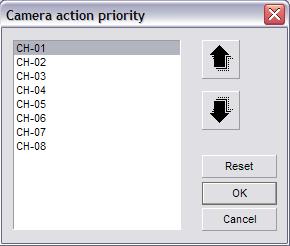
24 Alarm Actions Tab (Fig. 3-7) (Fig. 3-7) The Device Selection button will bring up the Device Select dialog box. (Fig. 3-8) Select your supported alarm relay controller from the Type drop down box. To configure the communication settings for your alarm relay controller select the COM Port button which will bring up the Communication Port dialog box. (Fig. 3-9) Set the correct device settings, refer to the manufacturer's specifications, using the associated drop boxes. The Camera Priority button will open the Camera Action Priority dialog box. (Fig. 3-10) Here you can raise or lower the priority of individual channels. When the Single Screen Preview feature is enabled, the channel with the highest priority will remain visible. This feature brings the alarm condition to your attention and will not change without user input, either by double-clicking the single screen or by selecting one of the Grid Layout buttons. 24
")
 25")
25 (Fig. 3-8) (Fig. 3-9) (Fig. 3-10) 25
 The Enable Motion Log check box will enable the motion detection based alarm condition triggering.")
26 The Alarm Recording check box will toggle alarm recordings. Alarm conditions include motion detection and external sensor triggers. The Show Motion Area check box toggles the motion detection zone box on the Live Preview. (p. 13) The Enable Motion Log check box will enable the motion detection based alarm condition triggering. This must be enabled for the E-map feature to pop-up on motion detection. It is also required for motion detection based triggering. The Single Screen Preview feature will maximize any video channel that detect s motion. If more than one video channel detects motion the Single Screen Preview will show the video channel with the highest priority based on the Camera Priority. (p. 24 ) The Error/Motion Output Trigger check box will enable motion detection based external alarm relay controller triggering. This must be enabled if you want motion detection to trigger an external alarm device. The Show Local Alarm Light check box toggles the display of a visual alarm light in the center of the screen during alarm conditions. The Enable Voice Alarm check box toggles an audible sound that plays through the speakers connected to the DVR Server when an alarm condition is detected (motion detection/alarm trigger). To select the sound to be played select the Alarm Response button. (Fig. 3-11) (Fig. 3-11) 26

27 The Alarm Response tab will allow you to set separate sound files for each sensor connected through the alarm relay controller when they are triggered. The Motion Response tab will allow you to set separate sound files to be played for each individual channel when motion is detected. The Error Response tab will allow you to set a single sound file for any error condition that occurs. To configure a sound file left-click on the desired sensor/channel and select the File Selection button. The standard Windows Open dialog box opens. Navigate to the directory where your sound file is located and highlight it. Once the sound file is highlighted, select the Open button to apply that sound file. The Popup E-Map check box enables the automatic showing of the E-Map when an alarm condition is detected. (p. 41) The Pre-recording check box, when enabled, will record seconds of video before the alarm condition happened. This will help aid in determining what events led up to the alarm condition. Relation Tab (Fig. 3-12) (Fig. 3-12) 27

28 The Relation tab allows you to configure any supported alarm relay controller device that you have connected to the DVR Server. To configure an individual sensor connected to the alarm relay controller select the sensor from the Sensor list. Once the sensor is highlighted select the Sensor Property button. The Sensor Property dialog box will appear. (Fig. 3-13) Determine if your sensor is a high or low level trigger and select the appropriate radio button. The ID field corresponds to which input you have your sensor connected to on the alarm relay controller. Input the proper number in the ID field. Using the Description field, you can give your sensors different names. Once you have your sensor configured select the Ok button to return to the Relation tab. (Fig. 3-13) You can link each individual sensor to either a video channel or an alarm output on the alarm relay controller. To configure the alarm outputs select the output number that the alarm device is connected to on the alarm relay controller by checking the box in Link To Output. Enter a description and select either High or Low for the Trigger. You can also select a High Level Pulse or a Low Level Pulse. The Pulse will trigger the output for a short time and then turn off. You can link several alarm outputs to a single sensor. To link a sensor to a video channel for recording select the sensor from the Sensor List. Then check the box next to the desired video channel under the Link To Video Channel. The Preset column allows you to enter a PTZ Preset Position number (p. 44) that the PTZ camera will automatically move to when the sensor is triggered. The Snapshot column will allow you to save a snapshot when the sensor is triggered. The Output column allows you to assign an alarm output number that will trigger the corresponding alarm device connected to that specific output on the alarm relay controller. The Matrix In column will display the video channel number that is entered on Public View 01. (p. 48) Guard Schedule Tab The Guard Schedule tab is where you configure the schedule for each sensor connected to the alarm relay controller. Unless a schedule is set and activated, the sensor(s) attached to the alarm relay controller will b e disabled. Refer to the Schedule Tab section for setup. (p. 21) 28
29 29

30 PTZ Tab (Fig. 3-14) (Fig. 3-14) To configure a PTZ camera select the video channel that the PTZ camera is connected to in the Channel List. Select the Load button to bring up the Predefined PTZ Ctrl Code dialog box. (Fig. 3-15) Locate the supported PTZ camera by scrolling down the list and select it by left-clicking, then select the Ok button. Once the protocol is configured, assign the correct address to the PTZ camera using the Address Index drop down box. Select the COM Port button to bring up the Communication Port dialog box. (Fig. 3-16) Configure each drop down box as specified by the PTZ camera manufacturer and select the Ok button to return to the PTZ tab. 30
 To select an external PTZ control device, such as a PTZ joystick,")

31 (Fig. 3-15) (Fig. 3-16) To select an external PTZ control device, such as a PTZ joystick, select the supported device from the Keyboard drop down box and select the COM Port button to bring up the Communication Port dialog box. (Fig. 3-16) Configure each drop down box as specified by the manufacturer. 31

32 Advanced Tab (Fig. 3-17) Video Standard: During the Initial Startup (p. 12) the video standard was already selected and should not need to be configured. Using the Date Style drop down box you can change how the date is displayed on the OSD. Recording Setup: The Single File Recording Time allows you to select the maximum amount of time before a new recording file is created. Remember that you cannot create a clip that spans multiple recording files and that the longer the Single File Recording Time is the longer it will ta ke to load before playing back. The Minimal Disk Space is the amount of free space needed on a partition to record video to. Once this value is reached the DVR Server will automatically free up more disk space to continue to record. The Auto Overwrite feature will automatically free up disk space (this will delete the oldest video recording files) and continue to record. The Disk Switching Alert will open a message box every time the server starts recording video to a different partition. You must click the Ok button before the DVR Server will start recording again. (Fig. 3-17) Others: The High-Quality Playback check box changes the playback quality. The 32
 is activated the Windows Sound Configuration will open and you will need to configure the microphone. The Messenger Service check box enables the Messenger Service dialog box pop-up. (Fig.")

33 Voice Chat check toggles the ability to use a microphone and speakers to talk between the Server and the Client. The first time the Voice Chat (p. 48) is activated the Windows Sound Configuration will open and you will need to configure the microphone. The Messenger Service check box enables the Messenger Service dialog box pop-up. (Fig. 3-18) This dialog box will appear at the bottom of the screen and display various messages pertaining to the DVR Server. The Audio Preview check box will toggle the Live Preview Audio in the Main DVR Screen. The Status Info check box toggles the display of the recording status information on each video channel preview image. The Instant Playback check box toggles the Instant Playback feature. (p. 47) (Fig. 3-18) The Watchdog drop down box allows you to setup a hardware watchdog. Use the COM Port button next to the Watchdog drop down box to configure the watchdog settings according to the manufacturer. The Matrix drop down box will allow you to select any of the supported matrix cards. Depending on the manufacturer you may or may not need to configure the COM port settings using the COM Port button. The Snapshot Path is the absolute path where all the snapshots taken will be stored. To select a different location select the Open button (open yellow folder) and select the desired directory. To change the name of the video channels select the Channel Description button. (Fig. 3-19) Type in a name for each channel in the Camera Description field. You can add an extended description to each channel by clicking the Extend Info button. (Fig. 3-20) The Extended Info is only editable here in the Setup Menu, you cannot change the text while viewing the Extended Info in the Live Preview mode. (Fig. 3-19) 33


34 (Fig. 3-20) To configure the storage partitions select the Disk Group Setup button. (Fig. 3-21) Select a disk group from the Group drop down box. All available partitions will be displayed. Check/un-check the box next to each partition to add/remove it from the disk group. You can assign different disk groups to different video channels. (p. 19) The Import Config and Export Config buttons will appear on all tabs. You can choose to import or export your DVR Server configuration. This allows you to copy your configuration to another DVR Server to quickly setup multiple DVR Servers or to backup your settings in case of emergency. To export your configuration select the Export Config button. The standard Windows Save dialog box appears where you will be able to choose the name and location to save your configuration field to. To Import a configuration file select the Import Config button. The standard Windows Open dialog box appears where you will be able to select a compatible configuration file to import. Once you import a configuration file, the settings will be automatically applied. Environment Tab (Fig. 3-22) (Fig. 3-21) System Startup: To have the DVR Server application automatically log into Windows XP/2000 on startup check the Auto Administrator Login When Windows Is Started check box. If the DVR Server is to be added to a domain select the Password button and type in the domain password in the New Password and Retype fields. To have the DVR Server application start when Windows XP/2000 loads check the Auto Startup This Program check box. The Auto Reindex Recording Files check box will reindex all recorded video files after 34

35 the DVR Server has finished loading. (Fig. 3-22) Environment: The Enable Client Connection check box needs to be checked to allow remote client users to successfully connect to the server. A log is created for every day that the DVR Server is running. To change the number of days that these logs are stored type in the desired number into the Log Info Keeping Period field. To have the DVR Server automatically restart check the Auto Restart check box. To specify when this restart will happen select the desired day, hour, and minute using the corresponding drop down boxes. It is recommended to restart at least once a week. To shutdown automatically check the Auto Shutdown check box and configure the day, hour, and minute drop down boxes. Auto Shutdown will only exit the DVR Server application. To have the entire PC turn off check the Power Off When Shutdown check box. The server application can be scheduled to automatically start at a specific time. To enable this feature check the Auto Start check box and select the desired hour and minute using the drop down boxes. For the Auto Start feature to function the PC must already be on and Windows XP/2000 must be running. To enable the DVR Web Server check the Enable Local Web Server check box. For the DVR Server/Web Server to be accessible from remote locations you must forward ports through 35
 Input the desired port number of the HTTP Port, which is used for the Web Server, and the Server Message, which is used for the Client Application. (Fig.")
 The System Clock dialog box will appear and allow you to change the system time and date. (Fig.")
36 the router to the DVR machine. To configure which port is used select the Network Ports button. (Fig. 3-23) Input the desired port number of the HTTP Port, which is used for the Web Server, and the Server Message, which is used for the Client Application. (Fig. 3-23) To synchronize the system clock to the local time select the Adjust Clock button. (Fig. 3-24) The System Clock dialog box will appear and allow you to change the system time and date. (Fig. 3-24) The Auto Reindex Recording Files check box will automatically start the reindexing process after the DVR Server application finishes loading. Due to imperfections in hard disk drive technology data corruption may occur. In this case you will need to reindex the recording files. The reindexing process scans each recorded video file and recreates the index file. Depending on how many recorded video files there are on the storage partitions this process may take up to two hours. If recorded video does not appear in the Playback mode or if the Playback mode takes more than five minutes to load it may indicate that there are missing or corrupt index files, you will need to reindex. During Daylight Savings when the time is set back one hour the DVR Server will have two recordings for that same hour. To correct this situation you must reindex. 36


37 User Button The User button will allow you to add/delete users and to modify their permissions. There are several buttons on the top of the User Admin dialog box. (Fig. 3-25) Hover the mouse cursor over these buttons to see what each of them are. To delete a user from the system select the user from the list and select the Delete button. To configure an existing user select the Modify button. To add an additional user select the Add User button, the Add User dialog box will appear. (Fig. 3-26) (Fig. 3-25) (Fig. 3-26) 37

38 Select the User level using the top radio buttons. The User Level determines client- until other users disconnect from the system. Fill in the Username, Password, Retype side bandwidth priority. If a user with a higher User Level logs into the system and there is not enough bandwidth for all users, the user with the highest User Level will be allocated the required bandwidth. The users with a lower User Level will have their connection interrupted Password, Full Name, and Description fields. You can disable a user by checking the Disable This User check box. This will not delete the user. To make a user the default user check the Default User check box. The default user is the user that automatically appears in the Lock/Exit dialog boxes. To enable specific cameras to be accessible by the user select the Camera Access button. The Camera Access dialog box appears. (Fig. 3-27) Check or un-check each camera that you want to enable/disable. To quickly enable all cameras select the Select All button. To quickly disable all of the cameras select the Clear button. (Fig. 3-27) To assign permissions to be granted to the user select the Authority button. The Assign Authority dialog box will appear. (Fig. 3-28) Check or un-check each of the selectable permissions for the user. To quickly remove all permissions select the Clear button. To quickly assign all permissions select the Select All button. 38

39 (Fig. 3-28) To create a backup copy of the configured users select File and then Save As. The standard Windows Save dialog box opens. By default the user backup will save to the Config Files Backup directory inside the DVR Server folder. To restore a User Backup File select File, then Load. The standard Windows Open dialog box will appear. Select the *.usr file to import. E-Map Button If this is the first time you have configured the E-Map you will see the E-Map dialog box. (Fig. 3.29) The E-Map feature is an advanced camera/sensor/alarm electronic map capable of embedding smaller maps inside of larger maps. 39

40 (Fig. 3.29) Select the Define A Root Node button to select the root map, this root map can contain embedded maps, cameras, sensors, and alarms. The standard Windows Open dialog box will appear. The default directory for map images is C:\Program Files\DVR\Emap. Select the root map image from the list and select the Ok button. You will now see the E-Map dialog box with your root map image. The E-Map Control Buttons are on the bottom of the dialog box. (Fig. 3-30) From left to right these are Zoom In, Zoom Out, Return To Parent Map, Fullscreen, Standard Zoom, and Move Thumbnail Map. (Fig. 3-30) To embed a map image inside the root map image right-click on the root map image. The E-Map Node dialog box will appear. (Fig. 3-31) Select Map Node from the Node Type drop down box. Input a name for the child map in the Description field. You can change the color of the Description text by using the Color button. Select the Open button (yellow folder). The standard Windows Open dialog box will appear and you will be able to select the map image. 40
 Select Camera from the Node Type drop down box.")
41 (Fig. 3-31) Creating Cameras, Alarm Outs, and Sensors will create an icon on the E-Map that will act as a shortcut to the associated video recording channel. To add a camera to the E-Map right-click on the map image to open the E-Map Node dialog box. (Fig. 3-31) Select Camera from the Node Type drop down box. Type in the channel number in the Channel field and fill in the Description field. Once the camera icon shows up on the map image you can click and drag the icon to the desired location. Upon closing the E-Map Node dialog box you will be asked to save the changes. To use the E-Map select the E-Map button on the DVR Main Screen. (p. 16) To view an embedded child map double-click the map icon. To bring up a video channel in Single Screen Preview double-click the camera icon. When you double-click the camera icon the E-Map will automatically close. Log Button The Log button will open the Log Viewer dialog box. (Fig. 3-32) The log file will provide more information about how the the DVR Server was functioning. Each log file is organized by date, there is one log file per day. You can sort by log entry type using the Type drop down box. You can also sort log entries by user with the Username drop down box. Use the Save button to create a backup copy of the log file. 41
 42")
42 (Fig. 3-32) 42
 The version number will be displayed in the title bar after the Extrafunction text. Each Extra Function has a shortcut key associated with it that is displayed before the button name.")
43 Extra Button DVR System The Extra button allows you to determine the version number that you are currently running. (Fig. 4-0) The version number will be displayed in the title bar after the Extrafunction text. Each Extra Function has a shortcut key associated with it that is displayed before the button name. These buttons include Extra Functions (p. 44), Snapshot (p. 44), Snapshot Viewer (p. 44), PTZ Preset Position (p. 44), Text Chat (p. 45), Audio Volume (p. 47), Instant Playback (p. 47), Start A Voice Chat (p. 48), Matrix Control (p. 48), External Command (p. 50), Video Parameters (p. 50), Remote Connection Control (p. 50), Switch Video Channel (p. 50), All Channels Start Recording (p. 51), All Channels Stop Recording (p. 51), Adjust PTZ Speed (p. 51), Force To Switch Recording File (p. 51), Running E-Map (p. 51), Activate Motion Detection For All (p. 51), Deactivate Motion Detection For All (p. 52), Channel Extend Info (p. 52), and Reindex Recording Files (p. 52). (Fig. 4-0) 43

44 Extra Functions Snapshot F1: This button will bring up the Extra Functions dialog box. F2: This button will take a snapshot of the currently selected channel and will be save to the default directory of C:\Snapshot Data. Snapshot Viewer F3: This button will bring up the Image Viewer and allow you to view, edit, and print any snapshot taken. (Fig. 4-1) Select the File menu, then select Open to open a snapshot image. Once the snapshot is loaded you can use various editing tools to enhance the image. (Fig. 4-1) PTZ Preset Position F4: This button will bring up the PTZ Preset Position Control dialog box. (Fig. 4-2) Begin by selecting the video channel that has a PTZ camera configured in the Live Preview. Select the PTZ button to display the PTZ camera controls. (p. 53) Point the PTZ camera at the desired location and select PTZ Preset Position in the Extra Functions dialog box or by pressing F4 on the keyboard. Left-click number 01 and select the Setting button. The Setting button stores the PTZ orientation to the selected number. Now select the Option button. This will open the PTZ Preset Point Info dialog box. (Fig. 4-3) To have this PTZ preset position be a cruise point check the Act As A Cruise Point check box. To have the PTZ camera pause at this point during cruising enter a number (in seconds) for the Staying Time field. The Description field allows you to assign a name to the cruise point. The Clear button will remove the PTZ cruise point information. These cruise points are stored in the PTZ camera itself and cannot be erased by the DVR Server application. To initiate the PTZ 44
 (Fig.")

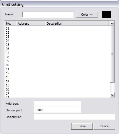
45 Cruising feature select the Cruise button. Each time the DVR Server application is closed PTZ cruising is stopped and will not start until the Cruise button is selected again. To have the PTZ camera orientate to a saved PTZ Preset Point select the number of the preset and select the Locate button. (Fig. 4-2) (Fig. 4-3) Text Chat F5: This button will bring up the Chat Room dialog box. (Fig. 4-4) To configure a chat room select the Setting button. The Chat Setting dialog box will appear. (Fig. 4-5) Set a name for the chat room using the Name field. Input the Address, Server Port, and Description using the fields at the bottom of the window. Select the text color using the Color button. This is the color of the text you type, the other users have their own separate colors. Select the Save button to return to the Chat Room dialog box. Type in a message in the bottom text field and select the Send button to have your message appear. The Clear All button will remove all sent/received text messages from the chat window. 45
")
46 (Fig. 4-4) (Fig. 4-5) 46
 Instant Playback F7: This button will open the Instant Playback dialog box. (Fig. 4-7) Use the Time Slider under the video feed to quickly fast forward/backward.")
47 Audio Volume DVR System F6: This button will allow you to adjust the volume of both the Waveout volume and Main Volume. (Fig. 4-6) (Fig. 4-6) Instant Playback F7: This button will open the Instant Playback dialog box. (Fig. 4-7) Use the Time Slider under the video feed to quickly fast forward/backward. The buttons (from left to right) are Save, Fullscreen Mode, Decrease Speed, Play, Pause, Stop, Increase Speed, Snapshot, and Exit. The Save button will open the standard Windows save dialog box and allow you to backup the Instant Playback video. The Fullscreen Mode button will maximize the Instant Playback video. To return from Fullscreen Mode right-click the mouse button anywhere on the screen. Use the Increase/Decrease Speed buttons to make the video play faster or slower. You can play as slow as ¼ real time speed and as fast as 16x real time speed. The Pause button will freeze playback. The Stop button will stop playback and move the time slider to the beginning of the Instant Playback video. The Play button will resume playback starting where the time slider is positioned. The Snapshot button will take a still image and allow you to save it. The Exit button will close the Instant Playback dialog box. 47
 Matrix Control F9: This button opens up the Matrix Switch dialog box. (Fig. 4-8) The Public View drop down box will select the Public View grid number.")
48 (Fig. 4-7) S tart A Voice Chat F8: This feature is a 2-way full duplex voice chat. It is initiated on the client side. Refer to Start A Voice Chat. (p. 73) Matrix Control F9: This button opens up the Matrix Switch dialog box. (Fig. 4-8) The Public View drop down box will select the Public View grid number. Public View 01 is the analog monitor connected to the first port of the Matrix card. Public View 02 is the analog monitor connected to the second port of the Matrix card. Once you have selected the Public View select any video channel to be shown on that Public View by left-clicking the channel number from the list. Once selected it will display Show next to it. 48
 The Description field allows you to rename the video channel.")

49 (Fig. 4-8) The Option button will open the Matrix Control Info dialog box for the currently selected video channel number. (Fig. 4-9) The Description field allows you to rename the video channel. The Relation To Public View check box will add that video channel number to the Auto Switching List. The Switch Interval field allows you to input the number of seconds you want that video channel to be displayed before switching to the next video channel. Select the Ok button to save the changes. The Enable Auto Switching check box on the Matrix Switch dialog box must be checked for the Public View to start the Auto Switch feature. (Fig. 4-9) 49
 You will be able to adjust the brightness, contrast, saturation, and hue for the currently selected video channel. Select the Default button to restore all parameters to their original values.")
 This window will display each connected user, their IP address, and which video channel they are connected to. This list is automatically updated.")
50 External Command F10: This bu tton will execute any external command that has been configured. Video Parameters DVR System F11: This bu tton will open the Video Parameters dialog box. (Fig. 4-10) You will be able to adjust the brightness, contrast, saturation, and hue for the currently selected video channel. Select the Default button to restore all parameters to their original values. (Fig. 4-10) Remote Connection Control F12: This button will open the Remote Connect dialog box. (Fig. 4-11) This window will display each connected user, their IP address, and which video channel they are connected to. This list is automatically updated. To force an update and get the latest list select the Refresh button. To disconnect all connected remote clients select the Disconnect All button. To disconnect a single video channel connection select the desired channel and select the Disconnect button. (Fig. 4-11) Switch Video Channel Tab: This button will cycle the video channel selection to the next video channel. You 50

51 will notice the white highlight box surrounding the currently selected video channel. All Channels Start Recording DVR System Ctrl+R: This button will start a recording in Manual recording mode on all channels if not currently recording. If a channel is disconnected recording will not start. All Channels Stop Recording Ctrl+S: This button will stop recording on all channels if not currently recording in Continuous Mode. If motion is detected the DVR Server will start recording again. Adjust PTZ Speed Ctrl+P: This button will allow you to change the speed at which the PTZ camera moves. This is especially useful when panning/tilting when zoomed in. Pressing Ctrl-P on the keyboard will bring up the Adjust PTZ Speed dialog box. (Fig. 4-12) Use the Horizontal/ Vertical Speed sliders or enter a number in the Horizontal/Vertical Speed fields. This will not change the speed at which the PTZ camera moves when the PTZ camera in Cruising. (Fig. 4-12) Force To Switch Recording File Ctrl+C: This button will create a new recording file for the currently selected video channel even if the Single File Recording Time (p. 32) has not been reached. Running E- Map Ctrl+A: This button will open the E-Map dialog box only if the E-Map has already been configured. (p. 41) Activate Motion Detect ion For All Ctrl+M: This button will start motion detection based recording on all channels if the 51
52 Motion Schedule is not already set. Deactivate Motion Detection For All Ctrl+D: This button will stop motion detection based recording on all channels if the Motion Schedule is not already set. Channel Extend Info Ctrl+E: This button will open the Notice dialog box. This is only a display, the text is not editable. To edit the Channel Extend Info use the Extend Info button. (p. 33) Reindex Recording Files Ctrl+Z: This button will start the Reindexing process. (p. 36) 52
 Use the arrows to pan and tilt. The + and buttons will focus, open/close the iris, and zoom in and out.")
53 PTZ Button DVR System To gain control of a configured PTZ camera start by selecting the channel in the Live Preview. Select the PTZ button, the panel will expand the PTZ controls. (Fig. 5-0) Use the arrows to pan and tilt. The + and buttons will focus, open/close the iris, and zoom in and out. The Auto Rotation button will slowly rotate the PTZ camera and may not be supported on all PTZ cameras. There are three other Function buttons that operate special PTZ camera functions such as wipe/clean glass and heater control. The F1/F2/F3 buttons may not be supported on all PTZ cameras. (Fig. 5-0) 53

54 Playback Mode DVR System The Playback mode allows you to review and backup recorded video files. (Fig. 6-0) You can playback a maximum of 16 channels at once. You can fast forward at 16x. Take note that playback at 16x on all 16 channels would be the same as playing back 256 channels at normal speed. Playback at 4x on all 16 channels would be the same as playing back 64 channels at normal speed. The PC system used for playback may not have the system resources to playback that many channels at once or at that playback speed. Be sure to monitor your CPU Usage in the Playback Information Window (p. 55) when playing back recorded video files to avoid unwanted issues. (Fig. 6-0) 54
 The channel number, video file size (in Mb), video file length (in seconds), bandwidth (in Mbps), video file start time, volume level, playback speed, and current playing time in green. (Fig.")
55 Playback Information Window DVR System The Playback Information Window displays the current date, time, and CPU usage in white on the top of the display. (Fig. 6-1) The channel number, video file size (in Mb), video file length (in seconds), bandwidth (in Mbps), video file start time, volume level, playback speed, and current playing time in green. (Fig. 6-1) Channel Grid The channel grid contains the playback video. This is where you will see all of your video recordings. You can select each channel by left-clicking on the desired grid square, this will also activate the audio for that channel. There is a full screen mode that you can toggle by clicking the right mouse button on the video feed. Grid Layout The arrangement of the Channel Grid is easily configured by 10 buttons. Hover your mouse cursor over these buttons for a description of each of the layout buttons. (Fig. 6-2) You can also zoom in and out by using the two buttons with the magnifying glass. Once zoomed in place your cursor over the edge of the video channel (the cursor will change to a pointing hand) and left-click to pan across the video feed. (Fig. 6-2) Calendar The calendar displays days that have recorded video footage in red, days with no video footage are displayed in black. (Fig. 6-3) To change months use the blue single arrow buttons. To change years use the blue double arrow buttons. To quickly change to the current date select the Today button. 55

 From left to right these are Previous File, Decrease Speed, Step Backward, Stop, Play, Pause, Step Forward, Increase Speed, Next File, Multiplay, and Stop All. (Fig.")
56 (Fig. 6-3) File List You can also search for video recordings using the File List. (Fig. 6-4) Simply select the date from the Date drop down box and the channel name from the Cameras drop down box. You will see a range of time indexes. Each time index is a single video recording file. To playback a recorded file select the desired time index and select the Play button. (Fig. 6-4) Playback Controls These controls will allow you to control the various aspects of playback. (Fig. 6-5) From left to right these are Previous File, Decrease Speed, Step Backward, Stop, Play, Pause, Step Forward, Increase Speed, Next File, Multiplay, and Stop All. (Fig. 6-5) Previous File Jumps to the beginning of the previous video recording file. Decrease Speed Slows down the playback speed to a minimum of ¼ real time 56

57 speed. Step Backward Moves the time slider back one frame and also pauses the video playback. Stop Stops playback of the currently selected video recording file. Play Starts playback of the currently selected video recording file from the beginning of the file. Pause Freezes playback of the currently selected video recording file. Step Forward Moves the time slider forward one frame and pauses the video playback. Increase Speed Increases the playback speed up to 16x real time speed. Next File Jumps to the beginning of the next video recording file. Multiplay Start s playback of all selected video channels. To select/de-select a video channel left-click on the Cam buttons in the Camera column. To quickly select all video channels double-click any of the Cam buttons. To quickly dechannels right-click any of the Cam buttons. select all Stop All Stops playback on all video channels. The Volume Buttons will increase/decrease the volume of all video channels. The Mute buttons will enable/disable the audio playback. The Exit button will close the Playback mode and return to Live Preview. (Fig. 6-6) (Fig. 6-6) The Clip button will allow you create a clip of the currently playing video file. (Fig. 6-6) To start a clip select the Clip button. The Clip Video File dialog box will appear. (Fig. 6-7) A Start Time will be displayed but no Stop Time. Select the Ok button to start recording a clip. The Clip Video File dialog box will disappear. Once you have passed the video portion that you want in the clip select the Clip button again. The Clip Video File dialog box will appear. (Fig. 6-7) A Start Ti me and Stop Time with both be displayed. To save the clip select the Ok button. The Files Backup Manager will appear. (Fig. 6-8) (Fig. 6-7) 57
 Select the device to save the clip file to using the Device Type drop down box.")
58 (Fig. 6-8) T ype in a name for the clip using the Filename field. Input a label using the Label field. Past labels will be displayed in the Label drop down box. Select the Backup button to continue. The Select Path dialog box will appear. (Fig. 6-9) Select the device to save the clip file to using the Device Type drop down box. Select the appropriate drive to save the clip file to using the Drive List drop down box. The Free Space and Space Needed displays will automatically update. Select the Save button to finish the clip creation process. (Fig. 6-9) The Smart Search button will open the Smart Search dialog box. (Fig The Smart Search is divided into two sections, the Video Preview Windows and the Smart Search Control Set. The Vi deo Preview Windows display the Playback video and the Search video. The Control Set displays all the Smart Search buttons along with the Video Results. With the Smart Search feature you are able to search through previously recorded video files for motion in the motion zones you create. You can also backup a Smart Search session for later review. 58

59 (Fig To start a Smart Search select the Setup button. The Setup dialog box will appear. (Fig. 6-11) Select the video channel you want to search through using the Channel drop down box. Next fill out the Start Time by selecting a start date with the drop down box and a start time using the time field. Then fill out the End Time by selecting an end date with the drop down box and an end time using the time field. After you have selected your searching range select the Ok button. The Setup dialog box will disappear and you will now see a video feed playing in the Search Window. You can change the recorded video file playing in the Search Window using the Previous Recorded Video File and Next Recorded Video File buttons. (Fig. 6-12) 59

60 (Fig. 6-11) (Fig. 6-12) You can now create one or more motion zones, each with individual sensitivity settings, to search through the recorded video files. The currently selected motion zone will be highlighted white, the rest will be red. To cycle through the motion zones, use the Switch button. To remove the currently selected motion zone select the Delete button. To clear all motion zones select the Clear button. Left-click and drag a motion zone around the desired area. A white square will appear. Set the sensitivity for the motion zone(s) and select the Search button, a progress bar will appear to display the search progress. While the search is being executed, you can temporarily pause by selecting the Pause button. To resume the search select the Continue button. Once the search has been completed, the video results will be displayed. To play a recorded video file highlight the desired file and select the Play button. You can also Pause and Stop the video. Select the Snapshot button to take a snapshot of the entire video frame. To backup any of the recorded video files select each recorded video file by left-clicking on them. To selected multiple recorded video files hold down the ctrl key and left-click on multiple recorded video files. Select the Backup button to backup the selected video files. You can save a Smart Search and review it at a later time. Select the Bookmark button to open the Bookmark dialog box. (Fig. 6-13) Input the name of your saved search in the Bookmark field. You can also type in a description of the saved search in the Description field. To save the search select the Ok button. 60
 Select the date in which the search was bookmarked using the Date drop down box, then select the name of the bookmark from the Bookmark drop down box.")
61 (Fig. 6-13) To review a saved Smart Search click the History button in the Smart Search dialog box. The History dialog box will appear. (Fig. 6-14) Select the date in which the search was bookmarked using the Date drop down box, then select the name of the bookmark from the Bookmark drop down box. The Delete button will remove the currently selected bookmarked smart search. The Clear All button will delete all bookmarked smart searches. Use the Select All button to select all recorded vide o results. The Inverse button will change the selection to the exact opposite of the currently selected recorded video results. The Delete button will remove the selected recorded video file from the bookmarked smart search. You can also backup recorded video files from the History dialog box. Select the Backup button to backup the selected video recording files. Use the Exit button to close the Smart Search and History dialog boxes. 61
 The Remote/SYNC Playback dialog box will appear. (Fig. 6-16) Using the Playback Mode drop down box you can choose between the two modes.")
62 (Fig. 6-14) Remote/SYNC Playback In local Playback there are two modes, the Local File Search Mode and the Local Synchronizer Search Mode. Select the Remote/SYNC Playback button. (Fig. 6-15) The Remote/SYNC Playback dialog box will appear. (Fig. 6-16) Using the Playback Mode drop down box you can choose between the two modes. The Local File Search Mode will playback the recorded video files directly from the recorded video file. This means that if you set the Single File Recording Time to 30 minutes the DVR Server will load that entire 30 minute video recording file before it starts playing back. The larger the Single File Recording Time the longer it will take to load each recorded video file. The Local Synchronizer Search Mode will stream the video from the recorded video file. Playback will start immediately but many of the Playback Controls will be unavailable due to the video stream. Local Synchronizer Search Mode will also playback selected video recording files in synchronization whereas the Local File Search Mode will not synchronize the playback. 62
 Browse And Print Image File The Browse And Print Image File button allows you to view previously saved snapshots and print them out. (Fig. 6-18) (p. 44) (Fig.")
63 (Fig. 6-15) (Fig. 6-16) Snapshot 17) The Snapshot button will take a still image of the currently selected video file. (Fig. 6- You can then save this image for later review. (p. 44) (Fig. 6-17) Browse And Print Image File The Browse And Print Image File button allows you to view previously saved snapshots and print them out. (Fig. 6-18) (p. 44) (Fig. 6-18) Manual Selecting File If you have recorded video files stored in a location other than the default directory the video recordings will not show up in the Calendar or the File List. Use the Manual Selecting File button to access the recorded video files. (Fig. 6-19) To browse for recorded video files select the Open button (yellow folder). (Fig. 6-20) The standard Windows Browse dialog box will appear. Locate the folder that the recorded video files are stored in and select the Open button. You will be returned back to the Select Video File dialog box. You can sort the recorded video files by channel, recording type, and by time index. Once you locate the 63
64 recorded video file you wish to play left-click on it so that it highlights. Select the Ok button and the video file will begin to play. (Fig. 6-19) (Fig. 6-20) Backup Files The Backup Files button (Fig. 6-21) will open the Backup Recording Data dialog box. (Fig. 6-22) From here you are able to backup multiple cameras simultaneously. During the last part of the backup the player software is automatically copied over along with the recorded video files. No other software is needed to review the saved video on a different PC system. 64
65 (Fig. 6-21) (Fig. 6-22) Use the Date drop down box to set a date ranger to filter the results. Use the Time fields to set a start time and end time to filter the results. The Recording Type drop down box will allow you to further filter the results by searching for only Motion/Manual/Continuous/ Network/Alarm based recordings. To search through multiple cameras check the box next to the channel name. The Select All button will automatically check all cameras. The Inverse button will select the exact opposite of the currently selected cameras. Select the Search button to begin the recorded video file search. In the results the Start/Stop Time, Length, Channel, Mode, and Disk will be displayed. Left-click a video file to select it. Hold down the ctrl key and left-click to select multiple recorded video files to backup. The Select All Files button will select all results. The Inverse button will select the exact opposite of the 65
 (Fig. 6-23) The Backup Tools button will open up Nero (if configured in.ini file) and allow you to add more files to a CD session.")
66 currently selected video files. The Cancel button will exit the Backup Recording Files dialog box. When you have selected the desired recorded video files select the Backup button. The Files Backup Manager dialog box appears. (Fig. 6-23) (Fig. 6-23) The Backup Tools button will open up Nero (if configured in.ini file) and allow you to add more files to a CD session. The USB Devices button will allow you to remove USB devices that you do not want to show up in the Device Type drop down box when finishing the backup process. Type in a name for the backup in the Label drop down box. Select the Backup button. The Select Path dialog box will appear. (Fig. 6-24) (Fig. 6-24) Select the backup device using the Device Type drop down box. If you select Compact Disc the Drive List drop down box will automatically select the CDR/W drive. Select the Save button to complete the backup process. 66
 Initial Startup The first time the DVR Client application is run a username/password dialog box will appear. (Fig. 7-1) By default the username is Supervisor and the password field is left blank.")
67 Client Setup Installation Client and Server applications are both included in a single installation package. Follow the Installation instructions. (p. 6) Initial Startup The first time the DVR Client application is run a username/password dialog box will appear. (Fig. 7-1) By default the username is Supervisor and the password field is left blank. Select the Ok button to login. After logging in you will see the DVR main screen. (Fig. 7-0) This screen contains the DVR Information Window (p. 68), Camera Status LEDs (p. 69), Channel Grid (p. 68), Grid Layout buttons ( p. 68), and the DVR Control Buttons (p. 69). (Fig. 7-0) 67

 Be sure not to overload the CPU.")
68 (Fig. 7-1) Channel Grid The Channel Grid contains the remote video preview. This is where you will see all of your connected video feeds. You can select each channel by left-clicking the mouse, selecting a channel will also activate the remote audio preview for that channel. Double-click a video channel to maximize it. To restore the Channel Grid double-click the video feed again. There is also a full screen mode that you can toggle by right-clicking on any video channel. DVR Information Window The current date and time are displayed here along with the CPU workload. (Fig. 7-2) Be sure not to overload the CPU. If the CPU Usage 100 the client machine may become unresponsive. The available hard disk drive space is also displayed here. The Free Space display is the free space available on the local hard disk drive, not the recording drive on the DVR Server. (Fig. 7-2) Grid Layout Buttons The arrangement of the Channel Grid is easily configured by 12 buttons. (Fig. 7-4) Hover your mouse cursor over these buttons for a description of each of the layout buttons. The Auto Group Switching button will cycle through each configured group. (Fig. 7-3) The Disconnect All button will close the connection to all connected video channels. (Fig. 7-5) 68
69 (Fig. 7-3) (Fig. 7-4) (Fig. 7-5) Camera Status LEDs There are four rows of Camera Status LEDs. (Fig. 7-6) The first row indicates channel The second row indicates channel You can connect to a maximum of 64 channels at once. The more channels you connect to the more system resources are needed to display the video feeds from the DVR Server. Each Camera Status LED will be a different color for each of the different connection types: Color Connection Indicator GREEN Connected GRAY No Connection RED Connection Lost/Failed BLUE Local Recording (Fig. 7-6) DVR Control Buttons (Fig. 7-7), (Fig. 7-8) The Extra button opens the Extra Function dialog box and will also tell you the version number. (p. 44) The Connect button opens the Connect Server dialog box and will allow you to connect up to 64 different video channels. (p. 75) The Disconnect button will close the connection to the currently selected video channel. The Record button will toggle the recording st atus of the currently selected video channel. The Video recording will be saved to the local hard disk drive. The Lock button is used to lock and unlock the DVR Client application. (p. 17) The Hide button will minimize the Client application to the Windows System Tray. The Exit button will close the Client application. (p. 17) The PTZ button will allow you to move any PTZ camera configured on the DVR Server that you are connected to. (p. 53) The E-Map button will pop up the client-side E-Map. (p. 41) The Playback button will open the Playback mode. (p. 54) The Setup button will open the Setup dialog box where you can configure the client-side settings. (p. 75) The Remote Control button will open the Control Remote Host dialog box. (p. 72) (Fig. 7-7) 69
 The Mute button will toggle the remote audio preview.")
 Select the time period (in minutes) that the alarm will be temporarily disabled using the Duration drop down box.")
70 (Fig. 7-8) Extra Button The Extra Function dialog box lists keyboard shortcuts for various features. (Fig. 7-10) The Mute button will toggle the remote audio preview. The Suspend Alarm Actions button will bring up the Suspend Alarm Actions dialog box. (Fig. 7-9) Select the time period (in minutes) that the alarm will be temporarily disabled using the Duration drop down box. The Hide button will hide the Client application. The Cancel button will close the Extra Function dialog box. (Fig. 7-9) 70
 PTZ Preset Position F4: This button will bring up the PTZ Preset position Control dialog box. (p. 44) The PTZ Preset Points are stored in the PTZ camera itself and will be the same on the server side and client side.")
71 (Fig. 7-10) Extra Functions Snapshot F1: This button will bring up the Extra Functions dialog box. (p. 70)(Fig. 7-10) F2: This button will ta ke a still image of the currently selected video channel. Snapshot Viewer F3: This button will bring up the Image Viewer dialog box. (p. 44) PTZ Preset Position F4: This button will bring up the PTZ Preset position Control dialog box. (p. 44) The PTZ Preset Points are stored in the PTZ camera itself and will be the same on the server side and client side. Text Chat F5: This button will bring up the Chat Room dialog box. (p. 45) Audio Volume F6: This button will allow you to raise and lower the audio volume. (p. 47) 71

72 Control Remote Host Machine F7: This button allows for remote activation of certain features. (Fig. 7-11) The configured servers are listed on the left. To gain control of a remote DVR Server select the server name. The server IP address can also be displayed alongside the server name by checking the Show Server Address check box. There are five actions that you can control remotely: Alarm In, Alarm Out, Guard, Record, and Motion. To start or stop any of these select the desired field and select the Start/Stop button. Starting and Stopping depends on the current schedule, the Start/Stop button may be grayed out for some actions. You can also restart and shutdown the currently selected DVR Server by using the Restart and Shutdown buttons. The Rediscover button will automatically close the Control Remote Host dialog box and rebuild the server list. If you have configured a server and it does not show up on the server list select the Rediscover button. The Parameters button will load the Web Client Configuration interface on top of the client application. The User Admin button will load the Web Client User Admin interface on top of the client application. (Fig. 7-11) 72
73 Start A Voice Chat DVR System F8: This button will start a two-way voice chat with the DVR Server. This feature requires a set of speakers and a microphone on both the client-side and server-side. Once selected the Starting Voice Chat dialog box appears. (Fig. 7-12) Use the Show Server Address check box to display the IP address along with the server name. Select a server and left-click the Call button to initiate a voice chat. To stop the voice chat select the Hangup button. The DVR Server will not receive a notification that the voice chat has started, but the microphone and speakers will be activated and ready to use. (Fig. 7-12) Auto Group Switch F9: This button will start the auto switching of any group configured to auto switch. You can have groups that do auto switch and groups that do not auto switch. You can have two channels switch while two other channels remain the same video feed. Vi deo Parameters F11: This button will bring up the Video Parameters dialog box. (Fig. 7-13) You can adjust the brightness, contrast, saturation, and hue of the currently selected video channel by dragging the slider(s) up and down. If you change these video parameters they will also affect the remotely recorded video files. 73

74 (Fig. 7-13) Disconnect All F12: This button will disconnect all video channels from the connected server(s). Adjust PTZ Speed Ctrl-P: This button will bring up the Adjust PTZ Speed dialog box and allow you to change the speed at which the PTZ camera moves when you pan/tilt/zoom. (p. 51) Running E-Map Ctrl-A: This button will open the client-side configured E-Map. Channel Extend Info Ctrl-E: This button will open the Notice dialog box. (Fig. 7-14) The video channel's extended information is taken from the server-side and displayed on the client machine. Use the DVR Server application to configure the Channel Extend Info. (p. 33) (Fig. 7-14) 74

75 Connect Button The Connect button w ill bring up the Connect Server dialog box. (Fig. 7-15) Use the Server or Group drop down box to select the desired server or group. Fill in the Username and Password fields with the right user info. Select each channel that you want to connect to by left-clicking them, they will highlight. You can also use the Select All button to quickly highlight all video channels. Check the Record At The Same Time check box to start local recordings of the connected video channels. The Disconnect Lower Level check box is used to automatically disconnect any user with a lower authority level if a user with a higher authority level tries to connect to the same video channel. This feature will utilize less bandwidth. Once the desired video channels are highlighted select the Ok button to connect to those video channels. Up to 64 remote channels can be connected to at one time. The Cancel button closes the Connect Server dialog box. You can automatically set the Channel Grid when connecting by using the Screen Mode drop down box. (Fig. 7-15) Setup Button The Setup button will open the Setup dialog box. (Fig. 7-16) The client setup is divided into four tabs: Connection (p. 76), Record (p. 78), Advanced (p. 79), and Environment (p. 80). 75

76 (Fig. 7-16) Connection Tab The Connection t ab is where the remote client connections are configured. Select the desired server from the Server List drop down box. Each configured video channel for the selected server will be displayed. To enable or disable the video channel check or un-check the Enabled check box next to the video channel. To disable all video channels select the Clear button. To enable all video channels select the Select All button. Use the Description field to type in a description. The Alarm Voice button will allow you to select a.wav file to play during an alarm condition on that channel. Use the Group field to assign that channel a group number. To configure a group select the Group Setup button, the Group Information dialog box will appear. (Fig. 7-17) Select a group by left-clicking on it. Once selected you can add that group to the Group Auto Switch list by checking the Enable Auto Switching check box. Use the Switching Interval field to input the number of seconds you want that group to display before switching to the next group. Use the Description field to change the name of the group. If you want to display 4 channels and have only the first channel auto switch configure 4 different groups. Under the Connection tab assign CH-01 and CH-02 to group 1. Assign CH-03 to group 2, CH-04 to group 3, and CH-05 to group 4. Select the Apply button, then the Ok button. Now select the Auto Group Switching button. 76

77 (Fig. 7-17) To configure a server select the Server Setup button, the Server Information dialog box will appear. (Fig. 7-18) Left-click on one of the servers to select it. Fill in the Address field with the DVR Server's IP address or resolvable host name. If you are on the local area network use the local IP for the DVR. If you are connecting from a different location use the static IP assigned by your ISP. Type in the number of channels that the DVR server has in the Channel Number field. The Description field is used to change the name of the server on the Server List. The Network Ports button is used to configure which port to use for the connection. (Fig. 7-19) Fill in the port number configured on the server side (p. 34) in the Server Message field and select the Ok button. The Disable Alarm Action check box is used to temporarily disable the alarm actions while the client is connected. The Clear button will restore the defaults for that server connection. The Log button will open the Log Viewer dialog box. (p. 41) The E-Map button will open the E-Map dialog box and allow you to configure the client-side electronic map. (p. 39) 77


78 (Fig. 7-18) (Fig. 7-19) Record Tab (Fig. 7-20) The Single File Recording Time drop down box specifies the maximum length of a recording file before a new file is created. The Minimal Disk Space field defines the amount of free hard disk drive space needed to record video locally. The Overwriting Trigger Value specifies the amount of free hard disk drive space is left before the client application starts overwriting the oldest recorded video files. The To Be Released Space field determines the amount of recorded video files will be deleted to make room for more current video files. The Enable Auto Overwriting check box will overwrite the oldest recorded video with the currently recording video files without any input from the user. To specify a directory to store these recorded video files select the yellow open folder by the Video File Path field. The standard Windows open dialog box will appear. Simply locate the desired 78

79 directory. (Fig. 7-20) Advanced Tab (Fig. 7-21) Signal Setting: The Quality drop down box sets the signal quality. A higher quality setting will record video files with a higher level of detail and a larger file size. The Compression drop down box sets the compression level of the recorded video files. A higher compression will have lower visual quality but a smaller file size. Environment: The Enable CPU Threshold check box will not allow you to connect to more channels once the CPU Usage has reached 100%. The E-Map Popup check box toggles the ability for the configured E-Map to automatically pop up during alarm conditions. The Auto Alarm Connect check box will automatically connect to any configured video channel that senses an alarm condition on the server-side. The Auto Remote Playback check box will automatically connect to the same server you are viewing under the Live Remote Preview when the Playback mode is entered. The Alarm Record check box will automatically start recording a connected video channel during an alarm condition. The Auto Re-connect check box will sense when a video channel has lost its connection to the server 79

80 and attempt to re-establish the connection. The Hi-quality Playback check box toggles the hight quality playback feature. On lower end client machines un-check this to improve performance. The Messenger Service check box will enable the Messenger Service pop up dialog box on the client-side. (p. 33) You can specify how many days that the client application will keep a log file before overwriting it by inputting the desired number of days in the Log File Keeping field. To change where the snapshots are stored select the yellow open folder button next to Snapshot File Path. A standard Windows open dialog box will appear in which you can specify the location that you want the snapshots to be stored in. The Auto-Switch With Screen Mode check box will automatically reconfigure the Channel Grid according to how many channels are in the group. (Fig. 7-21) Environment Tab (Fig. 7-22) System Startup: Check the Auto Administrator Login When Windows Is Started to have the client software login to Windows XP/2000. If the client machine belongs to a domain you must select the Password button and enter in your domain password. Check the Auto Startup This Program to have the DVR Client application start with Windows. 80

81 If you have several different DVR Server video channels assigned to the same group check the No Login Dialog Box. When you setup the server connection the Username and Password fields will no longer be grayed out. Others: The Keyboard drop down box allows you to configure a supported external device for controlling a PTZ camera. (p. 30) (Fig. 7-22) 81
 When using the remote client application some features/buttons may be grayed out and inaccessible. When using the remote client the Files Backup Manager is the Search Remote Recording File.")
82 Client Playback DVR System The DVR Client Playback mode and the Server Playback mode are the same. Refer to the Playback Mode. (p. 54) When using the remote client application some features/buttons may be grayed out and inaccessible. When using the remote client the Files Backup Manager is the Search Remote Recording File. The Backup Files/Remote Download button brings up the Search Remote Recording File dialog box. (Fig. 8-0) Use the Date drop down box to select the desired date. Use the Channel drop down box to select the desired video channel. With the Mode drop down box you can select what type of video recording to list. You can select All, Continuous, Motion, Alarm, Manual, and Network video recordings. A list of all video recordings will be displayed. They are listed as time indexes. The start and stop time for each video recording file id displayed. Select the desired times by left-clicking on the time index. To select multiple video recording files hold down the shift key and select more video recording files. The Select All button will highlight all listed recorded video files. The Clear button will clear the selection. Select the Download button to start the remote download process. A standard Windows open dialog box will appear. (Fig. 8-0) 82


83 Web Client DVR System You can access the DVR Server from Internet Explorer 6 or higher. The Web Client enables you to view up to 16 live preview video channels simultaneously. You can also review previously recorded video files and download them to the local machine using the Web Client. Port 80 must be forwarded to the DVR Server and the Enable Web Server check box needs to be checked (p. 32) in order to use the Web Client. Initial Startup First type in the DVR Server's IP address beginning with into the Address Bar and press enter. Choose English to start the Web Client. (Fig. 9-0) The default port for the Web Server is port 80. If you have changed this be sure to enter in the port along with the IP address when connecting to the DVR Web Server. If you are have not already done so select the Download button to download the required ActiveX control. (Fig. 9-1) In the File Download dialog box select the Run button. (Fig. 9-2) (Fig. 9-0) (Fig. 9-1) 83
 Once your browser has been restarted type in the IP address of the DVR Server in the Address Bar starting with http://. Choose English. (Fig. 9-0) Then select the Enter button. (Fig. 9-1) You will be prompted with a login screen.")
 There are eight buttons: Remote Setup (p. 85), User Manager (p. 113), Preview (p.")
84 (Fig. 9-2) The TCNVC.exe ActiveX control will now be downloaded and installed. Wait for the TCNVCInstall dialog box to appear and select the Ok button. (Fig. 9-3) You must restart your browser now. (Fig. 9-3) Once your browser has been restarted type in the IP address of the DVR Server in the Address Bar starting with Choose English. (Fig. 9-0) Then select the Enter button. (Fig. 9-1) You will be prompted with a login screen. (Fig. 9-4) Type in your Username and Password and select the Submit button. The Clear button will remove all text from the Username and Password fields. After you log into the DVR Web Server you will be presented with the Web Client Main Screen. (Fig. 9-5) There are eight buttons: Remote Setup (p. 85), User Manager (p. 113), Preview (p. 114), System Information (p. 120), Remote Status (p. 121), System Logs (p. 121), Remote Control (p. 121), and Playback (p. 124). In the top right there is a Refresh button that will update the page. 84


85 (Fig. 9-4) (Fig. 9-5) Remote Setup (Fig. 9-6) The Remote Setup allows you to configure all of the Setup Options (p. 18) that are on the DVR Server application. On the top right of the screen there is a Personal button. This button will open the Personal Configuration page. (Fig. 9-7) The Animation Effect check box will toggle the rotation animation for the Remote Setup. The Animation Time slider will increase/decrease the speed of the Animation Effect. You can choose whether the Animation Effect rotates to the right or to the left using the Animation Direction radio buttons. The Remote Setup page contains 12 menu items: Preview Setup (p. 86), Recording Setup (p. 89), Alarm Device (p. 91), Motion Detect Setup (p. 94), Error Setup (p. 95), Alarm Action (p. 97), PTZ Setup (p. 102), Matrix Setup (p. 104), Other Device (p. 106), Network Setup (p. 107), Advanced Setup (p. 108), and Customization (p. 112). Left-click on the menu item to open the respective pages. The Homepage button will open the Web Client Main Screen. The Back button will open the last open page. The Submit button will save and apply the changes to the DVR Server. 85
. The Video Parameter page allows you to change the video format to PAL or NTSC using the Standard radio buttons. (Fig.")
86 (Fig. 9-6) Preview Setup (Fig. 9-7) The Preview Setup menu contains the Video Parameter (p. 86), Color Scheme (p. 87), and the Color Scheme Schedule (p. 87). The Video Parameter page allows you to change the video format to PAL or NTSC using the Standard radio buttons. (Fig. 9-8) You can change how the OSD displays the date by using the Date Format drop down box. (Fig. 9-8) 86
 Up to five different Color Schemes can be set here using the Color Scheme drop down box. Use the Default button to restore the color settings to the originals.")
87 The Color Scheme allows you to change the brightness, contrast, saturation, and hue of each individual video channel. (Fig. 9-9) Up to five different Color Schemes can be set here using the Color Scheme drop down box. Use the Default button to restore the color settings to the originals. You can also create motion zones here. To create a motion zone left-click and drag a square around the desired area. You can create multiple motion zones each with a unique sensitivity level. The currently selected motion zone will be highlighted white, the rest will be red. To mask the currently selected motion zone check the Mask Area check box. Use the Switch button to cycle through the existing motion zones. To remove a motion zone or masked are select the Delete button while the desired zone is currently selected. Use the Sensitivity field to input a sensitivity level from 1 (highest sensitivity) to 100 (lowest sensitivity). (Fig. 9-9) The Color Scheme Schedule will allow you to configure the scheduling options for the Color Schemes. (Fig. 9-10) To select a scheme use the Color Scheme drop down box. Next select a Time Scheme by left-clicking on one of the listed Time Schemes. The selected Time Scheme will be displayed on the bottom of the page. Select the left arrow to apply the Time Scheme to a day of the week. To quickly copy the same Time Schedule to every day of the week use the Copy To button. Be sure to check the Activate Schedule check box to enable the schedule. The Delete All button will clear the applied Time Schemes. 87
")
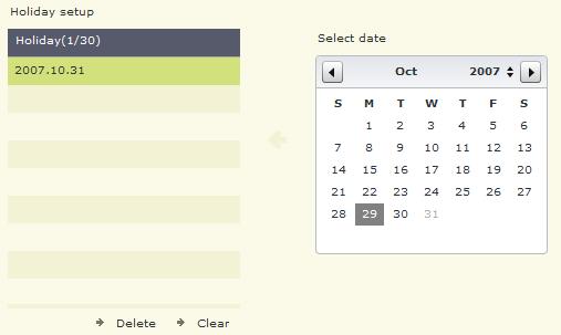
88 (Fig. 9-10) (Fig. 9-11) 88
89 The Holiday Setup button will open the Holiday Setup page. (Fig. 9-11) You can add up to 30 dates to the Holiday list. To add a date left-click a day on the calendar to highlight it. Now click the left arrow to add the date to the list. To remove a date from the list, left-click the desired date and click the Delete button. To empty the entire list click the Clear button. To edit a Time Scheme click the Edit button. The Time Scheme page will appear. (Fig. 9-12) To configure a Time Scheme click on Scheme1-Scheme16. Use the Period blocks to fill in a time period for the scheme. You can also use the Standard drop down box to apply common time periods to the scheme. Use the Name field to change the name of the scheme. Click the Clear button to remove all time periods from the scheme. Click the Save button to save the Time Scheme. (Fig. 9-12) Recording Setup (Fig. 9-13) The Recording Setup page contains the Recording Setup (p. 89), Video Scheme (p. 90), Video Scheme Schedule (p. 91), and the Continuous Schedule (p. 91). The Recording Setup page contains several configuration options that apply to all video recording channels. (Fig. 9-14) The Single File Recording Time drop down box allows you to set the maximum number of minutes a single recorded video file spans. If the recording time exceeds this value, a new recorded video file is automatically created. The Auto Overwrite check box will automatically overwrite the oldest recorded video files when the video storage drive(s) are full, when enabled. The Disk Switching Alert check box will popup a dialog box notifying you 89
 The Video Scheme page allows you to set the individual recording setup options for each video channel. (Fig. 9-15) You can set up to three different schemes.")
90 when the DVR Server switches video storage drives. The Minimal Disk Space field specifies the amount of free space needed to record video to a drive. (Fig. 9-13) (Fig. 9-14) The Video Scheme page allows you to set the individual recording setup options for each video channel. (Fig. 9-15) You can set up to three different schemes. To select a different video channel, left-click the name of the channel and it will highlight. The Video and Video/Audio radio buttons allow you to record just video or video with associated audio channels. The VBR Enabled check box overrides the user settings for video quality. In high motion situations the bit rate will rise, in low motion situations the bit rate will fall. The Limit Bit Rate check box will set a maximum bit rate for VBR to prevent a large video recording file from being created during constant high motion. The Resolution drop down box sets the recording resolution for the currently selected channel. Not all supported capture cards support all of the resolution modes. The Frame Rate (FPS) drop down box will allow you to set the frame rate from 1fps to 30fps. The Compression drop down box will allow you to set the level of compression for the recorded video files. The lower the 90

91 compression number, the smaller the recorded video file will be. This will allow more days of recording but at the cost of lower visual quality during playback. The Change On Alarm check box will automatically switch the Video Scheme to the configured settings when an alarm condition is detected, such as motion detection. The Compress Trans check box enables the dual-stream capability of the capture card (if supported). The DVR Server will record at the specified Video Scheme and send a separate video quality to the clients by using the Resolution, Frame Rate, and Compression settings. The Video Scheme Schedule is similar to the Color Scheme Schedule. (p. 87) The Continuous Schedule is similar to the Color Scheme Schedule. (p. 87) (Fig. 9-15) Alarm Device (Fig. 9-16) The Alarm Device page contains the Device Type (p. 91), Sensor Info Setup (p. 93), Output Info Setup (p. 93), Sensor Relation To Output (p. 94), Sensor Relation To Channel (p. 94), an d Guard Schedule (p. 94). The Device Type page contains the configuration options for all supported external alarm controllers. (Fig. 9-17) The Device Type drop down box specifies which supported alarm controller is connected to the DVR Server. Set the Com, Baud Rate, and Parity to match the settings of the connected alarm controller. The Data Bit and Stop Bit may not require configuration depending on the type of alarm relay controller. Set the IO Address to match the setting of the alarm controller. 91
")
 92")
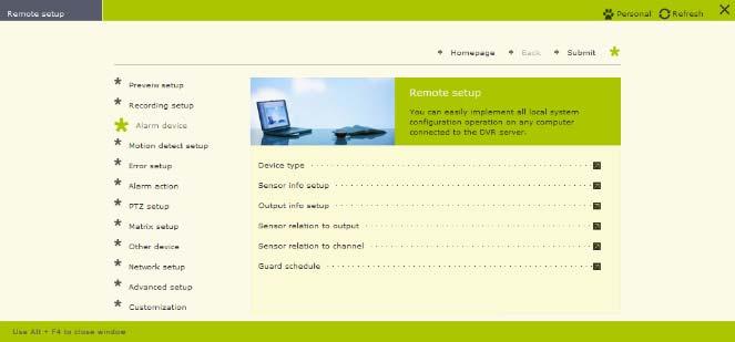
92 (Fig. 9-16) (Fig. 9-17) (Fig. 9-18) 92
 Select a sensor by leftclicking on it on the Sensor List. To change the name of a sensor use the Sensor Description field.")

93 The Sensor Info Setup page contains all the setup options for each external sensor connected to the DVR Server through an alarm controller. (Fig. 9-18) Select a sensor by leftclicking on it on the Sensor List. To change the name of a sensor use the Sensor Description field. The Sensor ID field needs to match the ID that the sensor is connected to on the external alarm controller. You can set the sensor trigger to either High or Low using the Trigger radio buttons. The Trigger will reverse the operation of the sensor if switched from the default. The Output Info Setup page contains the configurations for each external alarm output device. (Fig. 9-19) To select an alarm output device left-click an Output from the Output List. The Output Description field allows you to change the name of the output device. You can also set the mode of operation for the output device using the Trigger radio buttons. By default High is selected. By selecting Low the output device would be normally open as opposed to normally closed. (Fig. 9-19) (Fig. 9-20) 93

94 The Sensor Relation To Output page allows you to link sensors to outputs. (Fig. 9-20) Select a sensor by left-clicking, it will highlight green. Now select which output for the sensor to trigger by selecting an output and clicking on the left arrow. The output will be added to the list. To remove an added output click the right arrow. To clear all related outputs use the Clear button. The Standard Mode button will assign sensor 01 to output 01, sensor 02 to output 02, and so forth. The Sensor Relation To Channel page allows you to link sensors to trigger Alarm Recordings. (Fig. 9-21) Start by selecting the sensor by left-clicking. The selected sensor will highlight green. Left-click the desired channel and click the left arrow to add it to the list. To remove an added video channel use the right arrow. To clear all related video channels use the Clear button. The Standard Mode button will assign sensor 01 to ch- 01, sensor 02 to ch-02, and so forth. Each recorded video file triggered by an external sensor will be listed under the Alarm type when using the Playback mode. The Guard Schedule is similar to the Color Scheme Schedule. (p. 87) (Fig. 9-21) Motion Detect Setup (Fig. 9-22) This page contains the Motion Schedule (p. 94) and Motion Response (p. 94) pages. The Motion Schedule page is similar to the Color Scheme Schedule page (p. 87). The Motion Response page allows you to assign a Sound File and Hint Message to each individual channel. (Fig. 9-23) Use the Hint Message field to add text. This Hint Message 94
 Error Setup The Error Setup page allows you to configure the Error Response. (Fig. 9-25) The Error Response allows you to set a Sound File and Hint Message for an error condition.")
95 will be included in the automatically sent (if configured) from the DVR Server. The Sound File will play locally on the speakers connected to the server. (Fig. 9-22) (Fig. 9-23) Error Setup The Error Setup page allows you to configure the Error Response. (Fig. 9-25) The Error Response allows you to set a Sound File and Hint Message for an error condition. (Fig. 9-24) 95
")
96 (Fig. 9-24) (Fig. 9-25) 96
, PSTN Setting (p. 101), E-mail Setting (p. 101), Alarm Response (p. 101), and Camera Priority (p. 102) pages.")
97 (Fig. 9-26) Alarm Action (Fig. 9-26) This page contains the Alarm And Motion Detection (p. 97), Channel Relation To Output (p. 98), Channel Relation To Snapshot (p. 99), Short Message Setting (p. 99), PSTN Setting (p. 101), Setting (p. 101), Alarm Response (p. 101), and Camera Priority (p. 102) pages. The Alarm And Motion Detection page configures how the DVR Server reacts to alarm/motion conditions. (Fig. 9-27) The Alarm Recordi ng check box enables recordings triggered by alarm conditions such as motion detection. The Popup E-Map check box enables the E-Map feature. Once the E-Map is setup it will popup on screen for the security personnel to react to. The Single Screen Preview will maximize any channel that has motion and will not revert back until action is taken either by double-clicking the video feed or by using the grid layout buttons. (p. 115) The Show Motion Area check box will toggle the display of configured motion zones on the Live Preview mode. The Enable Motion Log check box will write a log entry each and every time motion detection triggers a recording or stops a recording. In multiple camera situations where motion is constantly triggered this may not be wanted. The log file will have many entries for motion and may make it difficult to read through. The Error/Motion Output Trigger check box enables motion detection based external alarm device triggering. The Show Local Alarm Light check box will toggle the display of an alarm light on the DVR Server when an alarm condition is detected. This will aid in the identification of certain situations for any security personnel monitoring the DVR. 97

 that the alarm continues to trigger.")
98 (Fig. 9-27) The Enable Voice Alarm check box toggles an audible sound that plays through the speakers connected to the DVR Server. The Snapshot Delay specifies the number of milliseconds to wait before automatically taking a Snapshot. The Recording Duration field specifies the length of time (in seconds) to record after the alarm has been triggered. The Alarm Duration field specifies the length of time (in seconds) that the alarm continues to trigger. The Channel Relation To Output page links motion detection to an alarm output device. (Fig. 9-28) 98

99 (Fig. 9-28) DVR System First select a video channel by left-clicking on the channel name. It will highlight green. Then select an output device by left-clicking on the output device name. Use the left arrow to add the output device to the list. Use the right arrow to remove an output device from the list. The Clear button will remove all output devices from the list. The Standard Mode button will set ch-01 to output 01, ch-02 to output 02, and so forth. The Channel Relation To Snapshot page allows you to automatically take a snapshot of the video feed during an alarm condition. (Fig. 9-29) You can select each individual channel by using the check box next to the channel name. The Snapshot check box will automatically apply to all channels. (Fig. 9-29) The Short Message Setting page contains the options for sending an SMS to your phone when an alarm action is detected. (Fig. 9-30) This feature requires a GSM enabled modem. The SMS Center field is supplied by your provider. The Number field is the cell phone number that the SMS will be sent to. The Description field is the text that will be sent. Be sure to check the Enable Action check box. Match the COM Port settings to that of your GSM modem. The Clear button will erase all settings. 99
")
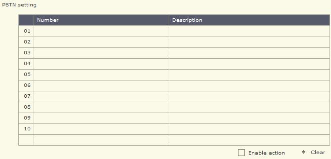
100 (Fig. 9-30) (Fig. 9-31) 100
 An additional modem must be installed and configured for this feature to work. Use the Number field to input a telephone number. Do not put parenthesis or hyphens.")
101 The PSTN page allows you to setup a telephone number to be dialed when the DVR Server detects an alarm condition. (Fig. 9-31) An additional modem must be installed and configured for this feature to work. Use the Number field to input a telephone number. Do not put parenthesis or hyphens. The area code is required if you are calling out of the home area that the server is in. Use the Description field to input a description. Be sure to check the Enable Action check box. The Clear button will erase all configured Numbers and Descriptions. The Setting page configures the on alarm feature. (Fig. 9-32) (Fig. 9-32) Type in the name of the sender in the Sender field. Input the address where the e- mail will be sent from in the Sender Address field. Type in the address of the mail server in the SMTP Server field. If your mail server requires a username and password check the My SMTP Server Need Checking Authorization check box. After the box is checked the Username and Password field will highlight. Fill in both the Username and Password fields. The Alarm Response page allows you to assign a sound file to be locally through the DVR speakers when a sensor is triggered. (Fig. 9-33) Use the Sound File field to assign a sound file to each sensor. Type in a description in the Hint Message field. This Hint Message is e- mailed if the feature is enabled and configured. 101
 PTZ Setup The PTZ Setup page contains the PTZ (p.")

102 (Fig. 9-33) The Camera Priority page allows you to assign different video channels a higher priority. (Fig. 9-34) This priority list is used along with the Single Screen Preview (p. 24). A video channel with a lower priority will not popup while a video channel with a higher priority is being displayed. (Fig. 9-34) PTZ Setup The PTZ Setup page contains the PTZ (p. 102) and Sensor Relation To Preset Point (p. 104) pages. (Fig. 9-35) The PTZ page allows you to configure the PTZ setup. (Fig. 9-36) Start by selecting the PTZ camera from the channel list, the video feed from the PTZ camera will be displayed. Use the Current PTZ Protocol drop down box to select your supported PTZ camera. Match the COM, Baud Rate, Parity, Address Index, Data Bit, and Stop Bit to the settings of the PTZ camera. The Fast Response To Remote Control check box will drop the currently queued frames for the client and send the last frame. This speeds up PTZ response on the client side. Use the Up, Down, Left, and Right arrows to move the PTZ camera. The Function buttons will activate manufacturer specific features that may not be available on all PTZ cameras, ex: lens wipe. There are also controls for focusing, iris control, and zooming to test the PTZ camera to ensure functionality. The Clear button will erase all 102
 (Fig.")
103 configured settings for the currently selected video channel. (Fig. 9-35) (Fig. 9-36) 103
 Start by selecting the desire configured sensor from the list, it will highlight green.")
104 The Sensor Relation To Preset Point page allows you to link an external sensor device to trigger a preset position on a PTZ camera. (Fig. 9-37) Start by selecting the desire configured sensor from the list, it will highlight green. Use the Preset Point field to type in the PTZ Preset Point number next to the video channel that is configured as a PTZ camera. (Fig. 9-37) (Fig. 9-38) M atrix Setup The Matrix Setup page contains the Matrix (p. 105) and Sensor Relation To Matrix Input 104

 Select a sensor by left-clicking the sensor name in the list, it will highlight green. Now type in the Public View number next to the desired video channel in the Matrix Input field.")
105 (p. 105) pages. (Fig. 9-38) The Matrix page contains the configuration options for the supported matrix cards. (Fig. 9-39) Use the Matrix drop down box to select the matrix card that has been installed. The COM, Baud Rate, Parity, Data Bit, and Stop Bit may not need to be configured depending on the type of matrix card selected. Refer to the manufacturer for required setup options. The Sensor Relation To Matrix Input page allows you to link an external sensor to a channel on the external matrix display grid. (Fig. 9-40) Select a sensor by left-clicking the sensor name in the list, it will highlight green. Now type in the Public View number next to the desired video channel in the Matrix Input field. Each time the sensor is triggered, the configured video channel will appear on the Public View number. (Fig. 9-39) (Fig. 9-40) 105
 The Keyboard page allows you to configure an external device to control the connected PTZ cameras. (Fig. 9-42) Use the Keyboard drop down box to select the supported PTZ control keyboard.")
106 (Fig. 9-41) Other Device The Other Device page contains Keyboard (p. 106) and Watchdog (p. 106) pages. (Fig. 9-41) The Keyboard page allows you to configure an external device to control the connected PTZ cameras. (Fig. 9-42) Use the Keyboard drop down box to select the supported PTZ control keyboard. Match the COM, Baud Rate, Parity, Data Bit, and Stop Bit settings to that of the selected keyboard. Refer to the keyboard s manual for the correct settings. The Watchdog page allows you to configure any installed Watchdog units. (Fig. 9-43) Select the supported Watchdog unit from the Watchdog drop down box. Select the COM port the Watchdog unit is connected to using the COM drop down box. Set the Baud Rate, Parity, Data Bit, and Stop Bit to match the settings of the selected Watchdog unit. Refer to the manufacturer s manual for proper configuration settings. (Fig. 9-42) 106

107 (Fig. 9-43) Network Setup This page contains the Network Setup (p. 107) and Network Schedule (p. 107) pages. (Fig. 9-44) The Network Setup page configures the network settings. (Fig. 9-45) The Enable Client Connection check box toggles remote access to the DVR Server. The Enable Local Web Server check box toggles the Local Web Server. This check box is grayed out in the Web Client. Use the HTTP Port field to input a port number for the Web Client to use. If you are accessing the DVR Server from outside the LAN you must forward this port through any router to the DVR Server. Use the Server Message field to input a port number for the DVR Client application to use. If you are accessing the DVR Server from outside the LAN you must forward this port through any router to the DVR Server. The Network Schedule is similar to the Color Scheme Schedule. (p. 87) (Fig. 9-44) 107
 The System Setup page contains several startup options. (Fig. 9-47) The Auto Administrator Login When Windows Is Started check box automatically logs in to Windows on boot.")
108 (Fig. 9-45) (Fig. 9-46) Advanced Setup This page contains the System Setup (p. 108), Environment (p. 109), Channel Associated (p. 110), Time Scheme Setup (p. 110), and Holiday Setup (p. 111) pages. (Fig. 9-46) The System Setup page contains several startup options. (Fig. 9-47) The Auto Administrator Login When Windows Is Started check box automatically logs in to Windows on boot. The Auto Startup This Program check box automatically starts up and locks the DVR Server application when Windows logs in. The Auto Reindex Recording Files check box will automatically reindex the video recording files when the DVR Server starts up. The more recorded video there is stored on the DVR server the longer this process will take. Use the New Password/Retype fields to input the domain password if the DVR Server is connected to a network running a domain controller. 108


109 (Fig. 9-47) (Fig. 9-48) The Environment page contains several environment options that determine the availability of certain features. (Fig. 9-48) The High-Quality Playback check box toggles the playback of unaltered video. When High-Quality Playback is disabled, you will see a lower quality video in the Playback mode but you will use less system resources. The Messenger Service toggles the Messenger Service popup window. When enabled a small dialog box will popup on the DVR Server for each event that occurs, such as a video loss event. The Audio Preview check box toggles the audio in the Live Preview mode. The Voice Chat check box enables/disables the voice chat feature. Voice Chat must be enabled on both the client and server. The Status Info check box toggles the RT (recording time) overlay on the lower left of the video feed. The Instant Playback check box enables the Instant Playback feature. (p. 47) Input the number of days (1-999) you want to save the server log into the Log Info Keeping Period field. After the specified number of days, the server logs will be overwritten 109

110 starting with the oldest log. The Auto Restart check box enables the automatic DVR restart feature. This feature will shut down the DVR Server application, log off Windows, and restart the system. You can choose to restart everyday or once a week. You must also input the time you want the DVR Server to restart. It is recommended to restart at least once a week. The Auto Shutdown check box enables the automatic closing of the DVR Server application. This feature will only exit the DVR Server application, Windows will continue to run. The Power Off When Shutdown check box will turn off the entire system when scheduled. The Auto Start check box enables the automatic power on of the DVR System. For this feature to function properly the +5VSB jumper must be connected on the Watchdog unit. The Snapshot Path specifies where the saved snapshots will be stored. To change the location click the yellow open folder icon. A standard Windows open dialog box will appear. (Fig. 9-49) The Channel Associated page is where you can rename individual video channels. (Fig. 9-49) Start by selecting a video channel from the Channel List, it will highlight green. The Signal Lost Alert check box will display a signal lost graphic on the video channel that has been disconnected. If the Messenger Service is enabled a dialog box will popup informing you of which channel has been disconnected. The Show Preview check box will enable the video feeds for the Live Preview mode. Without this checked you will not see your cameras. The Memo check box enables a memo addition to each channel that pops up each time a manual recording is started. The Allow Network Access check box will grant remote users access to the video channel. You can attach additional information to a recorded video file by using the Extend Info field. The Time Scheme Setup page allows you to customize each of the time schemes. (Fig. 9-50) 110

111 (Fig. 9-50) Start by selecting a scheme by left-clicking the scheme name, it will highlight green. Use the Name field to type in a name to identify the scheme. The Standard Mode drop down box contains pre-configured common time periods. Use the Period fields to define the time periods for the scheme. To save the new scheme left-click the Save button. The Clear button will remove all time periods from the selected scheme. The Holiday Setup allows you to associate specific dates to the Holiday when configuring the scheduling options. (Fig. 9-51) Use the calendar to select the desired date. To add it to the Holiday list click the left arrow. To remove a date from the Holiday list select the desired date and click the Delete button. To clear the entire Holiday list click the Clear button. 111

 Use either list to select a menu option.")
112 (Fig. 9-51) Customization The Customization page allows you create a custom menu for quicker operation. Click the Customization Setup button to open the Customization page. (Fig. 9-52) Use either list to select a menu option. Use the left and right arrows to add/remove items. (Fig. 9-52) 112
 Click the Add User button to add a u ser. The User Info page will appear. (Fig. 9-54) Input the username in the Username field.")

113 User Manager (Fig. 9-53) DVR System The User Manager page will display all configured users. To delete the currently selected user left-click the Delete User button. You cannot delete the Supervisor account. (Fig. 9-53) Click the Add User button to add a u ser. The User Info page will appear. (Fig. 9-54) Input the username in the Username field. Input a password in the Password and Verify Password fields. The Password and Verify Password fields must contain the same password. Optional: Input the name of the user in the Full Name field. Optional: Input a description of the user in the Description field. Select the authority level using the Level drop down box. If remote viewing is all that is needed for the user select the Low authority level. Check the Default User check box if you wan this user to be the default selected user when Locking/Unlocking, Exiting, or Logging in to the DVR system. You can disable a user by checking the Disable This User check box. Select the Cancel button to exit without saving. Select the Confirm button to exit and save the user. The Modify User Info button will open the User Info page and allow you to alter an existing user. (Fig. 9-54) 113
 You can check each individual check box or use the Authority check box to quickly check all authority permissions.")
114 (Fig. 9-55) The Assign Authority button will allow you to change the authority permissions of the currently selected user. (Fig. 9-55) You can check each individual check box or use the Authority check box to quickly check all authority permissions. The Camera Access button will allow you to grant/revoke permission for the selected user for each video channel. (Fig. 9-56) (Fig. 9-56) Preview (Fig. 9-57) When you click the Preview button you will see the Live Preview mode. This screen contains the Channel Grid (p. 115), Grid Layout buttons (p. 115), Available Channel list (p. 115), and DVR Control buttons (p. 116). 114

115 (Fig. 9-57) Channel Grid: The channel grid contains the live video preview. This is where you will see all of your video feeds. You can select each channel by left-clicking the mouse to activate the live audio preview for that channel. To maximize a video channel, double-click it. You will notice that once maximized, you will also see the other connected video channels in a picture-in-picture on the lower right. To restore the Channel Grid double-click the video feed again. There is also a full screen mode that you can toggle by clicking the right mouse button on any video channel. Grid Layout Buttons: You can rearrange the Channel Grid using the Grid Layout buttons. Hover your mouse cursor over the buttons to see what each one does. (Fig. 9-58) (Fig. 9-58) Available Channel List: All available channels to connect to are listed here. (Fig. 9-59) To select a single video channel left-click on the name and it will be highlighted. To select multiple video channels hold down the Ctrl key and left-click on the video channel names. The Select All button will highlight all available video channels. (Fig. 9-60) The Invert button will change the current video channel selection to the exact opposite. (Fig. 9-61) 115
116 (Fig. 9-59) (Fig. 9-60) (Fig. 9-61) DVR Control Buttons: These buttons are Snapshot (p. 117), Start Recording (p. 118), Remote Download (p. 118), and Playback (p. 119). (Fig. 9-62) (Fig. 9-62) These buttons are (from left to right) Connect Selected Channels, Disconnect Current Channel, and Disconnect All Channels. (Fig. 9-63) The Connect Selected Channels button will establish a connection to the currently selected video channels in the Available Channel List in the currently selected grid. The Disconnect Current Channel button will drop the connection to the currently selected video channel on the channel grid. The Disconnect All Channels button will drop the connection to all video channels. (Fig. 9-63) These buttons are Volume Set, Color Set, and PTZ Control. (Fig. 9-64) The Volume button will allow you to change the audio volume. (Fig. 9-65) Use the + and buttons to raise or lower the volume. To return to the DVR Control Buttons click the Volume button. The Video button allows you to change the brightness, contrast, saturation, and hue. (Fig. 9-66) Left-click the Video button to return to the DVR Control Buttons. (Fig. 9-64) (Fig. 9-65) 116
 (Fig.")
 The Snapshot dialog box allows you to preview the snapshot before saving it to disk. Select the Save button if you wish to save the snapshot.")
117 The PTZ Control button allows you to pan, tilt, and zoom any configured PTZ cameras on the DVR Server. (Fig. 9-67) Not all PTZ cameras support all PTZ control buttons. If you click on a button that is unsupported by the PTZ camera nothing will happen. Left-click the PTZ button to return to the DVR Control Buttons. (Fig. 9-66) (Fig. 9-67) Snapshot: The Snapshot button will take a picture of the currently selected video channel. Once clicked the Snapshot dialog box will appear. (Fig. 9-68) The Snapshot dialog box allows you to preview the snapshot before saving it to disk. Select the Save button if you wish to save the snapshot. The standard Windows Save As dialog box will appear where you can choose the location and name of the saved snapshot. If you do not want to save the snapshot select the Cancel button. 117

118 (Fig. 9-68) Start Recording: The Start Recording button will start recording the currently selected video channel. Once the recording starts you will be prompted for a location to save the recorded video files. When you are recording the Start Recording button will flash. To stop recording left-click the Start Recording button. Remote Download: The Remote Download button brings up the Search Remote Recording File dialog box. (Fig. 9-69) Use the Date drop down box to select the desired date. Use the Channel drop down box to select the desired video channel. With the Mode drop down box you can select what type of video recordin g to list. You can select All, Continuous, Motion, Alarm, Manual, and Network video recordings. A list of all video recordings will be displayed. They are listed as time indexes. The start and stop time for each video recording file is displayed. Select the desired times by left-clicking on the time. To select multiple video recording files hold down the Shift key and left-click on several video recording files. The Select All button will highlight all listed recorded video files. The Clear button will clear the selection. Once you have your video recording files selected they will highlight blue. Click the Download button to start the download. A standard Windows save dialog box will appear. 118
 To load a recorded video file click the Open button (yellow open folder).")

119 (Fig. 9-69) Playback: The Playback button will open up the Player application. (Fig. 9-70) To load a recorded video file click the Open button (yellow open folder). A standard Windows open dialog box will appear. Navigate to the recorded video file and click the Open button. The playback buttons are similar to the Playback mode. (p. 54) (Fig. 9-70) 119
 DVR System The System Information page will display information")

120 System Information (Fig. 9-71) DVR System The System Information page will display information about the DVR Server. The Software Version, CPU, Memory, OS, and Physical Disk are included on this page. Left-click the triangle to expand/collapse menu items. (Fig. 9-71) (Fig. 9-72) 120

121 Remote Status (Fig. 9-72) DVR System This page contains the System Status (p. 121), Channel Status (p. 121), AlarmIn Status (p. 121), and AlarmOut Status (p. 121) pages. The System Status page contains the Process, Service, Memory/CPU, Logical Disk, and NIC Flux pages. The Process page displays the currently running processes on the DVR Server. The Service page displays the currently active services running on the DVR Server. The Memory/CPU page displays the current memory and CPU usage on the DVR Server. The Logical Disk page displays each drive connected to the DVR Server along with the total size and free space of each partition. The NIC Flux page displays the current bandwidth usage for the DVR Server. The Channel Status page displays the current status of each video channel. (Fig. 9-73) The Channel Name, Recording Status, Motion Detection Status, and Network Connections are displayed. You can connect to a video channel by selecting it and clicking the Connect button. To close the connection to the channel click the Disconnect button. The AlarmIn Status and AlarmOut Status pages will display the current state of each external sensor and each external alarm output device. (Fig. 9-73) System Logs (Fig. 9-74) Click the Update button to refresh the display. Select a log file to view by highlighting a day from the Date list. To print the currently visible page click the Print Current Page Button. To print all pages of the log file click the Print All Page button. The Type drop down box will allow you to filter the log files based on Info, Warning, Function, Error, and All entries. While viewing the System Log the Type drop down box will filter according to Application, Security, and System. Use the Homepage button to exit the System Logs page. Remote Control (Fig. 9-75) The Remote Control page contains the Channel Control (p. 122), AlarmIn Control (p. 123), AlarmOut Control (p. 123), and Windows Control (p. 123) pages. 121


122 (Fig. 9-74) (Fig. 9-75) The Channel Control page allows you to remotely start and stop Manual video recordings. The Recording Status column displays the current recording status of each channel. The color indicators are: green manual recording, yellow motion recording, blue continuous recording, gray not recording. Select a channel from the Channel column and click the Connect button to see the video feed from that channel. The Disconnect button will close the connection to the currently selected channel. Once connected, doubleclick the Recording Status camera icon to start a manual recording on the DVR Server. 122
 set. (Fig.")
 (Fig.")

123 Double-click again to stop the recording. The AlarmIn Control page allows you to activate/deactivate external sensors that do not have a Guard Schedule (p. 94) set. (Fig. 9-76) To activate a sensor select the sensor from the AlarmIn column and double click the activation icon in the Guarding Status column. To deactivate the sensor double-click the Guarding Status icon again. (Fig. 9-76) (Fig. 9-77) The AlarmOut Control page allows you to remotely trigger any external alarm device. (Fig. 9-77) Select an output device from the AlarmOut column. Double-click the Triggering Status icon to activate the alarm output device. Double-click again to stop the alarm output device. The Windows Control page allows you to remotely restart/shutdown the DVR Server. (Fig. 9-78) The Restart Remote Computer button will restart the DVR Server. The Shutdown Remote Computer button will turn off the DVR Server. (Fig. 9-78) 123
 Hover your mouse over the Grid Layout buttons for a description of each one. (Fig. 9-80), (Fig. 9-81) Hover your mouse over the Playback buttons for a description of each. (Fig. 9-79) (Fig.")
124 Remote Playback DVR System The Remote Playback page allows you to playback up to 16 channels from the DVR Server remotely through the Web Client. (Fig. 9-79) Hover your mouse over the Grid Layout buttons for a description of each one. (Fig. 9-80), (Fig. 9-81) Hover your mouse over the Playback buttons for a description of each. (Fig. 9-79) (Fig. 9-80) (Fig. 9-81) To playback a video file select a date from the Date drop down box. Select a channel from the Cameras drop down box. Use the Type drop down box to filter the recorded video files by Continuous, Alarm, Motion, and Manual recordings. Left-click a time period and press the Play button to review that recorded video file. The Speed field will display the current playback speed. Use the Decrease Speed button to slow the playback speed down to ¼ real time speed. Use the Increase Speed button to speed up playback up to 16x real time speed. Use the Time Slider to quickly search through the playing recorded video file. 124
Unisight DVR System. Unisight DVR Manual. Version Rev 1.0
 Unisight DVR Manual Version 1.8.0131 Rev 1.0 1 Table of Contents System Requirements...5 Server Hardware Requirements...5 Server Software Requirements...5 Client Hardware Requirements...5 Client Software
Vegas Valley Video Systems. Vegas Valley DVR Manual TZHC Series Server
 Vegas Valley DVR Manual TZHC Series Server 1 Table of Contents Initial Startup...4 Initial Setup...4 Live Preview Mode...5 DVR Information Window...6 Camera Status LEDs...6 Channel Grid...7 Grid Layout
Unisight DVR System. Unisight DVR Manual. Ver rev1.3.4
 Unisight DVR Manual Ver2.7.1027 rev1.3.4 1 Table of Contents System Requirements.8 Unisight DVR Server.. 8 Server Hardware Requirements...8 Server Software Requirements 8 Client Hardware Requirements...
Unisight Digital Technologies. Unisight DVR Manual Client
 Unisight DVR Manual Client 1 Table of Contents Initial Startup...4 Initial Startup...4 Channel Grid...6 DVR Information Window...6 Grid Layout Buttons...7 Camera Status LEDs...7 Extra Function Buttons...7
PROFESSIONAL PROTECTION INCORPORATED
 PROFESSIONAL PROTECTION INCORPORATED EAGLE EYE DIGITAL VIDEO RECORDING AND SURVEILLANCE SYSTEMS 1101 Tyvola Road Suite 202 Charlotte North Carolina 28217-3515 Business: (704) 523-1660 Facsimile: (704)
USER MANUAL. Mac Version
 USER MANUAL Mac Version Contents 1 Software Introduction... 1 1.1 Summary... 1 1.2 Install and Uninstall... 1 1.2.1 Install the Software... 1 2 Login Software... 3 2.1 Login... 3 2.2 Control Panel Instruction...
NVMS User Manual. Version 2.1.0
 NVMS-1000 User Manual Version 2.1.0 Contents 1 Software Introduction... 1 1.1 Summary... 1 1.2 Operation Environment... 1 1.3 Install and Uninstall... 2 1.3.1 Install the Software... 2 1.3.2 Uninstall
Central Management Software. Cam Viewer 3 Lite. User Manual
 Central Management Software Cam Viewer 3 Lite User Manual Version 1.0.0 Table of Contents 1. System Requirement...4 2. Software Installation...5 3. Configuration Wizard...9 3.1 Channel...10 3.1.1 Adding
NVMS User Manual
 NVMS-1000 User Manual Contents 1 Software Introduction...1 1.1 Summary... 1 1.2 Operation Environment... 1 1.3 Install and Uninstall... 2 1.3.1 Install the Software... 2 1.3.2 Uninstall the Software...
NVMS User Manual
 NVMS-1000 User Manual Contents 1 Software Introduction...1 1.1 Summary... 1 1.2 Operation Environment... 1 1.3 Install and Uninstall... 2 1.3.1 Install the Software... 2 1.3.2 Uninstall the Software...
Video Management Software
 Video Management Software User Manual Web: europesecurity.eu Mail: info@europesecurity.eu Tel.: 0541 352 952 User s Manual 2 Contents CHAPTER : XMS CENTRAL USER MANUAL 1 PC REQUIREMENT 3 2 INSTALL 3 3
Unisight Digital Technologies. Unisight DVR Manual TZHC Series Installation
 Unisight DVR Manual TZHC Series Installation 1 Table of Contents System Requirements...3 Server Hardware Requirements...3 Server Software Requirements...3 Client Hardware Requirements...3 Client Software
Intelligent Security & Fire Ltd
 Copyright 2007-2009 Cortex Global Table of contents: Introduction... 3 1. Login... 3 1.1 Advanced login options... 4 2. Preview... 5 2.1 Main menu... 6 2.2 Camera list... 6 2.3 Main display... 6 2.4 Maps...
NVMS1000. User Manual
 NVMS1000 User Manual Contents 1 Software Introduction... 1 1.1 Summary... 1 1.2 Operation Environment... 1 1.3 Install and Uninstall... 2 1.3.1 Install the Software... 2 1.3.2 Uninstall the Software...
SecuGuard. Basic 5.0. User s manual. Dec Version: 5.0.x
 SecuGuard Basic 5.0 User s manual Dec. 2009 Version: 5.0.x SecuGuard Basic System Requirement...5 Installation...6 Before Installing the Software... 6 Starting the Installation... 6 Quick Start...9 Install
User s Manual of DVR ULTIMAX. Remote Client Software V wersja 2.40
 User s Manual of DVR ULTIMAX Remote Client Software V 4.0.1 ULTIMAX-304 ULTIMAX-308 ULTIMAX-316 ULTIMAX-504 ULTIMAX-508 ULTIMAX-516 ULTIMAX-704 ULTIMAX-708 ULTIMAX-716 wersja 2.40 Index 1 Software Install,
YesCam View User Manual For Easy Connection YesCam Series
 YesCam View User Manual For Easy Connection YesCam Series Seeing the video from anywhere Version:1.2.4 Date:2015.02.3 1 Table of Content 1. Introduction...4 2. System Requirement...4 3. Install YesCam
NVMS1000. User Manual
 NVMS1000 User Manual Contents 1 Software Introduction... 1 1.1 Summary... 1 1.2 Operation Environment... 1 1.3 Install and Uninstall... 2 1.3.1 Install the Software... 2 1.3.2 Uninstall the Software...
Multi-NVR Manager. Quick Start Configuration Usage
 Multi-NVR Manager Quick Start Configuration Usage 2014. All rights are reserved. No portion of this document may be reproduced without permission. All trademarks and brand names mentioned in this publication
IP Solution Intelligent Surveillance Solution
 IP Solution Intelligent Surveillance Solution user s manual Table of Contents TABLE OF CONTENTS TABLE OF CONTENTS...1 SYSTEM REQUIREMENT...5 INSTALLATION...6 QUICK START...10 1. MAIN CONSOLE...14 1.1 Start...16
SKY l SYS DVR USER S MANUAL TABLE OF CONTENTS. Skydreamers Systems DVR Page 1
 TABLE OF CONTENTS Main System Application (Control) SERVER Startup Screen 6 Login/Logout/Shutdown 7 Control Screen 7 Setup 7 System Power Management 8 Auto Switching Interval 8 E-map 8 TV-Out 8 On-screen
SecuGuard. Basic 5.0. Version: xxx
 SecuGuard Basic 5.0 Ł` ˆª Ø Version: 5.0.2.xxx SecuGuard Basic ` Ø ˆ ˆ...6 ˆ Ø...7 Ł ˆ Ø»ˆÆ ˆ`... 7 ˆŁ` ˆ Ø»ˆÆ ˆ`... 7 Ø Æ Ł...10 Ø IP Camera(s)... 10 Ł` IP Camera(s)... 10 ˆ Ø Ł ˆ ˆ :... 14 Playback:...
User Manual. Central Monitoring Software for TER-series recorders. CenPro
 EN User Manual Central Monitoring Software for TER-series recorders CenPro Contents CENPRO USER MANUAL 1 PC REQUIREMENT 3 2 INSTALL 3 3 UNINSTALL 5 4 BASIC OPERATION 7 4.1 Log In 7 4.2 Screen Layout 8
32 CHANNEL SURVEILLANCE SYSTEM MANUAL
 32 CHANNEL SURVEILLANCE SYSTEM MANUAL English version 1.0 SOFTWARE GUIDE Software Guide for Digimerge Networkable Cameras Copyright 2007 Digimerge Technologies Inc. 32-CH Surveillance System Note This
Lorex Client 7.0 & Lorex Message Master
 Lorex Client 7.0 & Lorex Message Master Software Manual English Version 1.0 MODELS: L19WD Series www.lorexcctv.com Includes L19WD800 & L19WD1600 Copyright 2008 Lorex Technology Inc. Table of Contents Table
VMS-A1 Client Software. User Manual
 VMS-A1 Client Software User Manual Contents Contents... 2 Chapter1. Overview... 4 1.1 Description... 4 1.2 Features & Functions... 4 Chapter2. Update Info... 6 Chapter3. Starting VMS-A1... 7 3.1 Installing
PIVOT CMS CLIENT SOFTWARE USER MANUAL
 PIVOT CMS CLIENT SOFTWARE USER MANUAL 1 CMS USER GUIDE 1.1 PC REQUIREMENT Recommended PC Requirement OS CPU VGA RAM HDD Graphics Card OS CPU VGA RAM HDD Windows Vista, 7 or higher Intel Core2Quad Q9400
Digital Recorder End User Guide. Official UK distribution partner
 Digital Recorder End User Guide Official UK distribution partner 2 Installer Information Contents General Operation Mouse Operation Logging into the System Quick Menu PTZ Control 4 5 5 6 Playback Operation
Digital Video Surveillance Center Management Software
 Digital Video Surveillance Center Management Software NVClient User Manual Revision: V3.2 Updated: 12-2011 Contents Chapter I General...- 3-1.1 INTRODUCTION... - 3-1.2 MAIN FUNCTIONS... - 3 - Chapter II
User s Guide. Valvova Oy
 User s Guide Valvova Oy June 21, 2017 CONTENTS Contents 1 Timeline 2 1.1 Program startup......................................... 3 1.2 Calendar............................................. 3 1.3 Go to
icms Pro USER S Manual Ver 1.4
 icms Pro USER S Manual Ver 1.4 Contents Panes... 7 How Can User Rights Affect Your Use of icms Pro SW?... 10 Minimum System Requirements... 11 Installing the icms Pro SW... 12 Download icms Pro from icatchinc
errors, or places that do not match the product. If you have any unsolved please contact our technical support department.
 - 0 - Statement: This manual may contain several technical inaccuracies or typographical errors, or places that do not match the product. If you have any unsolved problems in the process of using product
Digital Recorder End User Guide
 Digital Recorder End User Guide metcalfeallen www.metcalfeallen.co.uk - 01884 38222 - admin@metcalfeallen.co.uk Installer Information Metcalfe Allen Ltd Unit 7 Saunders Way Kingsmill Industrial Estate
Avigilon Control Center Web Client User Guide
 Avigilon Control Center Web Client User Guide Version: 4.12 Standard PDF-WEBCLIENT-S-E-Rev2 Copyright 2013 Avigilon. All rights reserved. The information presented is subject to change without notice.
NetClient software user manual
 NetClient software user manual 1-1. General information Net Client is an application which provides users not only viewing and controling remote DVRs, but also receiving realtime event data or alarm signals
Table of Contents. Chapter 1 Overview In This Manual RASplus Features Product Information Chapter 2 Installation...
 Remote Administration System Plus (RASplus) Table of Contents Chapter 1 Overview... 1 1.1 In This Manual... 1 1.2 RASplus Features... 1 1.3 Product Information... 1 Chapter 2 Installation... 3 Chapter
NVR Client system. User Guide
 NVR Client system User Guide Content Chapter1 Start up and Main interface 2 1.1 Start up 2 1.2 Main interface 6 1.2.1 Interface description 6 1.2.2 Select playback channel 8 1.3 System Menu 11 1.3.1 Remote
VMS2.0 Client Software. User Manual
 VMS2.0 Client Software User Manual Chapter 1 Contents Brief Introduction...1 1.1 Description... 1 1.2 Running Environment...1 Chapter 2 Installation... 2 Chapter 3 Live View... 4 3.1 User Login...4 3.2
Pro7400H1 Hybrid DVR User Manual
 Pro7400H1 Hybrid DVR User Manual User Information Admin User Name: Admin Password: IP Address: System Name: Table Of Contents 1. Menu Operation... 4 1.1 Main Menu... 4 2. Start Up/Shutdown System... 5
The Intelligent Surveillance Solution. User manual
 The Intelligent Surveillance Solution User manual CONTENTS 1.1 System Requirement... 1 1.2 Installation... 1 1.3 Quick Start... 5 2.1 Start Menu... 10 2.2 Information Window:... 12 2.3 PTZ Config:... 12
Central Management Software for NVR-915 / NVR-1615 CV5-M256
 Central Management Software for NVR-915 / NVR-1615 Table of Contents Chapter 1. Main Console... 4 1.1 Tool Bar... 4 1.2 NVR List... 5 1.3 Division List... 7 1.4 Group List... 9 1.5 PTZ Panel...11 1.6 Operation
Manual Version: V1.15. Video Management Software Guard Station User Manual
 Manual Version: V1.15 Video Management Software Guard Station User Manual Thank you for purchasing our product. If there are any questions, or requests, please do not hesitate to contact the dealer. Disclaimer
W Box VMS BOX T E C H N O L O G I E S.
 W Box VMS BOX T E C H N O L O G I E S www.wboxtech.eu Contents Contents... 1 Overview... 3 1.1 Description... 3 1.2 Running Environment... 3 1.3 Function Modules... 3 Live view... 6 2.1 User Registration
icms Pro USER s MANUAL Ver 1.0
 icms Pro USER s MANUAL Ver 1.0 Contents Target Audience for this Document... 5 Copyright, Trademarks and Important Information... 5 Copyright... 5 Disclaimer... 5 Introduction... 6 Tabs... 6 Panes... 7
Pro71600N3 NVR User Manual
 Pro71600N3 NVR User Manual User Information Admin User Name: Admin Password: IP Address: System Name: Table Of Contents 1. Menu Operation...4 1.1 Main Menu...4 2. Start & Shutdown System...5 2.1 Start
Using the VSOM Operator Pages
 CHAPTER 8 The VSOM Operator Pages provide access to features that video surveillance operators can use to view, record, search, and control video. This chapter describes the Operator Pages in detail. It
Table of Contents. Chapter 1 Overview In This Manual ATVision Pro Features Product Information... 1
 Remote Management Software (ATVision Pro) Table of Contents Chapter 1 Overview... 1 1.1 In This Manual... 1 1.2 ATVision Pro Features... 1 1.3 Product Information... 1 Chapter 2 Installation... 3 Chapter
IMS200 SURVEILLANCE SYSTEM USER MANUAL
 IMS200 SURVEILLANCE SYSTEM USER MANUAL 1 PRECAUTIONS The contents of this manual may change due to product upgrades or other reasons. We have the right to make changes of the contents without notice. This
Manual Version: V1.01. Video Management Server Client Software User Manual
 Manual Version: V1.01 Video Management Server Client Software User Manual Thank you for purchasing our product. If there are any questions, or requests, please do not hesitate to contact the dealer. Notice
Client Software-4000(V ) User Manual
 User Manual") Client Software-4000(V2.00.02) User Manual Index Chapter 1 Welcome to Client Software-4000 (V2.0)... 1 1.1 Overview... 1 1.2 Computer Disposition Request... 1 1.3 Convention... 1 Chapter 2 Install & Uninstall...
Client Software-4000(V2.00.02) User Manual Index Chapter 1 Welcome to Client Software-4000 (V2.0)... 1 1.1 Overview... 1 1.2 Computer Disposition Request... 1 1.3 Convention... 1 Chapter 2 Install & Uninstall...
How to Use exacqvision with Hikvision Devices V2.0.1
 How to Use exacqvision with Hikvision Devices V2.0.1 Contents 1. Overview... 2 1.1 About exacqvision... 2 1.1.1 Client/Server Architecture... 3 1.2 Current Test Environment... 4 2. Start VMS... 5 2.1 Login...
LOREX CLIENT Remote Agent Software
 LOREX CLIENT Remote Agent Software Instruction Manual English Version 1.0 MODEL: L500 Series www.lorexcctv.com Copyright 2006 LOREX Technology Inc. Table of Contents Table of Contents About the Lorex Client...
Mirasys NVR. User s Guide
 Mirasys NVR User s Guide CONTENTS Contents... 2 Before you start... 3 Introduction... 6 Logging in... 9 User interface... 13 Navigator... 16 Cameras... 25 Video outputs... 41 Digital outputs... 46 Digital
Chapter 3 Operating instructions
 Chapter 3 Operating instructions Summary This chapter describes the how to control and navigate through the TVR 30 s menus and options. Content Control interfaces 10 Controlling the TVR 30 10 Front panel
RemoteManager USER S MANUAL
 Remote Monitoring Software RemoteManager USER S MANUAL Thank you for purchasing our products. Before operating the system, please read this User s Manual thoroughly and retain it for future reference.
Control Software centralized HEM. User Manual
 Control Software centralized HEM User Manual Page: - 2-1. Product Overview This software (HEM-HyperElectronicsMappers) for remote control is designed to be installed into a PC for use within a surveillance
Contents Contents. Chapter 1. Program Installation. Chapter 2. For the start of CMS. Chapter 3. Monitoring. Chapter 4. E-Map Mode
 CMS User's Manual Contents 0 Contents Chapter 1. Program Installation 1.1 PC specifications 1.2 Program Installation Chapter 2. For the start of CMS 2.1 Site Registration Setup (Network Camera Registration)
DiViS Net (Integration)
") DiViS Net (Integration) Installation and User s Guide Ver 12.00.1 Digital Video Security System Digital Video Recorder www.divisdvr.com Chance-i USA Corp. *All contents of this document may change without
DiViS Net (Integration) Installation and User s Guide Ver 12.00.1 Digital Video Security System Digital Video Recorder www.divisdvr.com Chance-i USA Corp. *All contents of this document may change without
Pro7804N1 NVR User Manual
 Pro7804N1 NVR User Manual Pro7804N1 User Manual BW R6.indd 1 User Information Admin User Name: Admin Password: IP Address: System Name: Table Of Contents 1. Menu Operation...4 1.1 Main Menu...4 2. Start
Table of Contents Surveillance Center Overview...3 Log...30 Live Camera Panel...31 Live Camera Panel Explained I...32
 Surveillance Center Overview...3 Introduction...3 System Requirements... 4 Features... 5 Checking the Hardware Requirements... 6 Installing and Accessing the Module... 8 Connecting a Camera to the Network...
LOREX CLIENT 3.0 SOFTWARE MANUAL IRMS Integrated Remote Management Software
 LOREX CLIENT 3.0 SOFTWARE MANUAL IRMS Integrated Remote Management Software Instruction Manual English Version 2.0 Copyright 2007 Lorex Technology Inc. www.lorexcctv.com Table of Contents Overview... -
Manual Version: V1.01. ISS Manager Video Management Software User Manual
 Manual Version: V1.01 ISS Manager Video Management Software User Manual Notice The information in this manual is subject to change without notice. Every effort has been made in the preparation of this
DiViS Net (Integration)
") DiViS Net (Integration) Installation and User s Guide Ver 12.12.0 Digital Video Security System Digital Video Recorder www.divisdvr.com DiViS DVR.com *All contents of this document may change without prior
DiViS Net (Integration) Installation and User s Guide Ver 12.12.0 Digital Video Security System Digital Video Recorder www.divisdvr.com DiViS DVR.com *All contents of this document may change without prior
Before Setting. GMS is an integrated security management system that provides a useful solution for central monitoring station operation.
 GMS MANUAL Before Setting What What is is GMS? GMS? GMS is an integrated security management system that provides a useful solution for central monitoring station operation. Minimum Minimum System System
Table of Contents. Chapter 1 Overview In This Manual RASplus Features Product Information Chapter 2 Installation...
 Remote Administration System Plus (RASplus) Table of Contents Chapter 1 Overview... 1 1.1 In This Manual... 1 1.2 RASplus Features... 1 1.3 Product Information... 1 Chapter 2 Installation... 3 Chapter
DVR Server Users Manual
 DVR Server Users Manual System Guide... 4 Precaution in Use... 4 Product Guide... 4 Live View... 5 Server Login... 7 Power Off... 7 On-Screen Display (OSD)... 8 View Screen... 8 Digital Zoom... 9 Video
Figure 4-9. Click Finish button, system pops up a dialogue box. Click the OK button, the startup wizard is complete. See Figure 4-10.
 For detailed information, please refer to chapter 4.11.4.1.1. Figure 4-9 Finish button, system pops up a dialogue box. the OK button, the startup wizard is complete. See Figure 4-10. Figure 4-10 4.4 Preview
RemoteManager Software
 RMS RemoteManager Software User Manual Contents of this user manual are protected under copyrights and computer program laws. Functions or configurations are subject to be changed or modified without prior
RAS (Remote Administration System)
") RAS (Remote Administration System) Digital Video Recorder Software User Guide Document 900.0314 Rev 2.00 RAS User Guide Revisions Issue Date Revisions 1.00 08/04 New document. 1.01 04/05 Update template,
RAS (Remote Administration System) Digital Video Recorder Software User Guide Document 900.0314 Rev 2.00 RAS User Guide Revisions Issue Date Revisions 1.00 08/04 New document. 1.01 04/05 Update template,
P r o f e s s i o n a l 4. 6 G e t t i n g S t a r t e d G u i d e
 Milestone XProtect P r o f e s s i o n a l 4. 6 G e t t i n g S t a r t e d G u i d e Dear Milestone Customer, With the purchase of Milestone XProtect Professional you have chosen a very powerful and intelligent
Quick Start Guide (V1.03) UD.6L0201B1064A01
 UD.6L0201B1064A01") ivms-4200 PCNVR Quick Start Guide (V1.03) UD.6L0201B1064A01 Thank you for purchasing our product. If there is any question or request, please do not hesitate to contact the dealer. This manual applies
ivms-4200 PCNVR Quick Start Guide (V1.03) UD.6L0201B1064A01 Thank you for purchasing our product. If there is any question or request, please do not hesitate to contact the dealer. This manual applies
SAFEGUARD CONTENTS. Digital Video Recorder. Version 1.3. Page. DVR Server S A F E G U A R D
 S A F E G U A R D SAFEGUARD Digital Video Recorder Version 1.3 CONTENTS Chapter 1 Chapter 2 Chapter 3 3.1 3.2 3.3 3.4 3.5 3.6 3.7 3.8 3.9 Chapter 4 4.1 4.2 Remote Client Chapter 5 Chapter 6 Chapter 7 7.1
Intelligent Security & Fire
 Milestone XProtect Basis 4.0 Milestone XProtect Basis+ 4.0 Getting Started Guide 2005 PDF version Dear Milestone Customer, This Getting Started Guide explains how to install and use key features in Milestone
Surveillance_client Software Operation Manual
 Surveillance_client Software Operation Manual Contents 1 Product Description... 3 1.1 Important Disclaimer... 3 1.2 Software Related Files...3 1.2.1 Software Installation Directory... 3 1.3 Application
User s Manual. Surveillance Client PC Software for Windows OS & Mac OS Central Management Software. Surveillance Client
 User s Manual Surveillance Client PC Software for Windows OS & Mac OS Central Management Software Surveillance Client Contents 1 Product Description...4 1.1 Important Disclaimer...4 1.2 Software Related
VIPER. Quick User Guide
 VIPER Quick User Guide 1 2 Please read this manual thoroughly before use and keep it handy for future reference. Contents 1. Overview... 1 1.1 DVR Description... 1 1.2 DVR power up... 1 1.2.1 Login...
AVerMedia. AverDiGi EH5116 PRO. Quick Installation Guide
 AVerMedia AverDiGi EH5116 PRO Quick Installation Guide i SPECIFICATIONS ARE SUBJECT TO CHANGE WITHOUT PRIOR NOTICE THE INFORMATION CONTAINED HEREIN IS TO BE CONSIDERED FOR REFERENCE ONLY WARNING TO REDUCE
Secure Guard Central Management System
 Speco Technologies, Inc. Secure Guard Central Management System Usage Information Contents 1 Overview... 7 2 Installation... 7 2.1 System Requirements... 7 2.2 System Installation... 7 2.3 Command Line
NVMS-7000 Client Software User Manual Version 1.03
 NVMS-7000 Client Software User Manual Version 1.03 Contents Chapter 1. Overview... 3 1.1 Description... 3 1.2 Running Environment... 3 Chapter 2. Starting NVMS-7000... 4 2.1 User Registration... 4 2.2
DVR SYSTEM User s Manual
 DVR SYSTEM User s Manual Manual Revision : Version 5.3 above Release Date : July 1. 2004 INDEX Chapter. Main Screen -1. Explanation of Main Screen A ~ N Functions per button -2. Pan/Tilt Control O Pan/Tilt
Bosch Recording Station. Operating Manual
 Bosch Recording Station en Operating Manual Bosch Recording Station Table of Contents en 3 Table of Contents 1 Program Start/Login 5 1.1 Starting the Program 5 1.2 Logging on to the System 5 1.2.1 Logging
Linksys Video Monitoring System User Guide
 Linksys Video Monitoring System User Guide BUSINESS SERIES Model: LBAVMS16 Linksys is a registered trademark or trademark of Cisco Systems, Inc. and/or its affiliates in the U.S. and certain other countries.
ipoint Ultra v6.32 Client User Manual ipoint Ultra v6.32 Client USER MANUAL
 ipoint Ultra v6.32 Client User Manual ipoint Ultra v6.32 Client USER MANUAL I ipoint Ultra v6.32 Client User Manual Content Chapter 1 Start up and Main interface... 8 1.1 Disk management... 8 1.2 Start
NVMS-5000 NVMS User Manual
 NVMS-5000 NVMS-5000 User Manual NVMS-5000 User Manual Contents 1 Introduction... 4 1.1 NVMS-5000 Brief Introduction... 4 1.1.1 Summerization... 4 1.1.2 Software Architecture... 4 1.2 System Components...
AVerMedia IWH3216 Touch Quick Installation Guide
 AVerMedia IWH3216 Touch Quick Installation Guide NOTICE SPECIFICATIONS ARE SUBJECT TO CHANGE WITHOUT PRIOR NOTICE. THE INFORMATION CONTAINED HEREIN IS TO BE CONSIDERED FOR REFERENCE ONLY. WARNING TO REDUCE
ipims USER s MANUAL (ORION IP Device Total Management SW) Ver 1.2 by sj
 Ver 1.2 by sj") ipims USER s MANUAL (ORION IP Device Total Management SW) Ver 1.2 by sj Contents Contents... 2 Target Audience for this Document... 5 Minimum System Requirements... 5 Introduction... 6 Tabs... 6 Panes...
ipims USER s MANUAL (ORION IP Device Total Management SW) Ver 1.2 by sj Contents Contents... 2 Target Audience for this Document... 5 Minimum System Requirements... 5 Introduction... 6 Tabs... 6 Panes...
Genie XMS Central Management Software
 Enterprise-Level, Intelligent Analysis, Distributed Connectivity User s Manual Copyright EverFocus Electronics Corp, Release Date: January, 2015 Notice: The content is subject to change without notice.
User`s Manual. CMS Pro. Professional Central Monitoring Software. Full-featured Enterprise Class Surveillance Solution
 Professional Central Monitoring Software CMS Pro Full-featured Enterprise Class Surveillance Solution User`s Manual This document contains preliminary information and is subject to change without notice.
Blue v2 INSPIRE DVR RANGE USER MANUAL
 INSPIRE Blue v2 DVR RANGE USER MANUAL Contents Logging into the DVR Mouse menu Live viewing Playback Smartphone viewing setup Smartphone viewing Copy to USB/Disc Using Cop player 2 playback software Using
eview Network Video Recorder User s Manual
 eview Network Video Recorder User s Manual Version 1.02 2010/02/09 Copyright 2010, All rights reserved. Contents 1. Starting / Closing...1 2. Monitoring...4 2.1. Monitoring Windows Layout...4 2.2. Full
Camera Control for Windows
 Camera Control for Windows 1910012275 REV1.1.0 Contents Chapter 1 Introduction... 1 1.1 Overview... 1 1.2 System Requirement... 1 Chapter 2 Software Installation... 2 Chapter 3 Quick Start... 5 3.1 Create
SmartWatch Eco/Eco Compact
 SmartWatch Eco/Eco Compact Digital Video Recorders SmartWatch Eco SmartWatch Eco Compact Quick User Guide Index Box Contents...3 Front Panel Controls...4-5 SmartWatch Eco Compact...4 SmartWatch Eco...5
VCS version Rockside Road Cleveland, Ohio
 User Manual VCS version 5.0 4807 Rockside Road Cleveland, Ohio 44131 216-901-1726 www.acuity-vct.com Introduction 1 System Requirements 1 Overview 1 Getting Started 2 Installing the Java Runtime Environment
Avigilon Control Center Standard Web Client User Guide. Version 5.6
 Avigilon Control Center Standard Web Client User Guide Version 5.6 2006-2015, Avigilon Corporation. All rights reserved. Unless expressly granted in writing, no license is granted with respect to any copyright,
Quick Installation Guide
 Quick Installation Guide For Bundles Featuring the QC4098 or QC4096 Network DVR 8 and 6 Channel H.64 Compression All-in-One DVRs with Variable CIF and D Recording Options PART - PACKAGE CONTENTS QC4098
TruVision DVR 60 Quick Start Guide
 Content Package contents 1 Installation environment 1 Setting up the TVR 60 1 Connecting the devices 2 Turning on and off the TVR 60 2 Operating the TVR 60 3 DDNS settings 5 Live mode 5 Quick Archive 5
Quick Start Guide. Menu Structure. Startup and Shutdown. Using the Setup Wizard. DS-8100-S Series DVR (V2.0.1)
") Quick Start Guide DS-8100-S Series DVR (V2.0.1) Menu Structure The menu structure of the DS-8100-S Series DVR is as followed: 1. Enter the Shutdown menu by clicking on Menu > Shut down. 2. Select the Shutdown
Quick Start Guide DS-8100-S Series DVR (V2.0.1) Menu Structure The menu structure of the DS-8100-S Series DVR is as followed: 1. Enter the Shutdown menu by clicking on Menu > Shut down. 2. Select the Shutdown
PCMS User Manual. User Manual PCMS. A-Series DVR (Cloud)
") PCMS User Manual A-Series DVR (Cloud) User Manual PCMS User Manual PCMS A-Series DVR (Cloud) 1 PCMS User Manual A-Series DVR (Cloud) Contents 1. Brief Introduction... 3 2. Application... 3 3. OS Compatibility...
PCMS User Manual A-Series DVR (Cloud) User Manual PCMS User Manual PCMS A-Series DVR (Cloud) 1 PCMS User Manual A-Series DVR (Cloud) Contents 1. Brief Introduction... 3 2. Application... 3 3. OS Compatibility...
Network Video Recorder
 Network Video Recorder Quick Operation Guide No. Name Function Description POWER Turns green when NVR is powered up. READY The LED is green when the device is running normally. The light is green when
INSTRUCTION MANUAL. NC-Titanium. Please read this manual thoroughly before use, and keep it handy for future reference.
 INSTRUCTION MANUAL NC-Titanium Please read this manual thoroughly before use, and keep it handy for future reference. Table of Contents Chapter 1 Introduction... 1 1.1 Features... 1 1.2 System Requirements...