2 IDS LCD Keypad User Manual C Issued March 2009
|
|
|
- Ezra Dennis
- 6 years ago
- Views:
Transcription
1
2 2
3 3
4 4
5 Contents 1. Introduction to the IDS LCD Digital Keypad Arming the Control Panel Away Arming How to Away Arm Quick Away Arm Shortcut Key Stay Arming How to Stay Arm Quick Stay Arm Shortcut Key How to Stay Arm and Go Key-switch or Remote Arming Auto Arming Disarming the Control Panel How to Disarm with a User Code How to Disarm using a key-switch or Remote Bypassing Zones How to Bypass a Zone How to Un-bypass a Zone Emergency Alarms Fire Alarms Panic Alarms Medical Alarms Duress Alarms Alarm Memory Zone Options Changing a Zone Name User Codes Adding, Deleting and Editing User Codes How to Enter the User Program Mode Explanation of Programmable Options Option 0 Add a New User Code Option 1 Edit a User Name Option 2 Edit a Selected User Code Option 3 View a User Code Slot Number Option 4 User Code Properties Explanation of User Code Properties Master Code Duress Code Maid s Code Global Arm/Disarm Group Arm Group Disarm Report User Open/Close User Phone in Access Report User Access Enable Anti-Pass Back for User
6 Fire Code Option 5 Assign User Code to Partitions Option 6 Assign User Code to Doors Option 7 Assign User Code to Schedule Option 8 Adding User Remotes Option 9 Delete User Code (Code Known) Option 10 Delete a User Code (Slot Known) Option 11 Viewing a User Code Option 12 Add User Slot Stay Zones How to Select a Stay Profile How to Program Stay Zones How to Cancel Stay Zones Buzz Zones How to Program Buzz Zones How to Cancel Buzz Zones Chime Zones How to Program Chime Zones How to Cancel Chime Zones Viewing Trouble Conditions Changing a Partition Remote Telephone Access Output Control via a Keypad
7 Tables Table 1 Alarm Panel Zones...13 Table 2 Alarm Panel Features...14 Table 3 User Programming Options...15 Table 4 User Code Properties...19 Table 5 Trouble Conditions...27 Table 6 Remote Telephone Operation
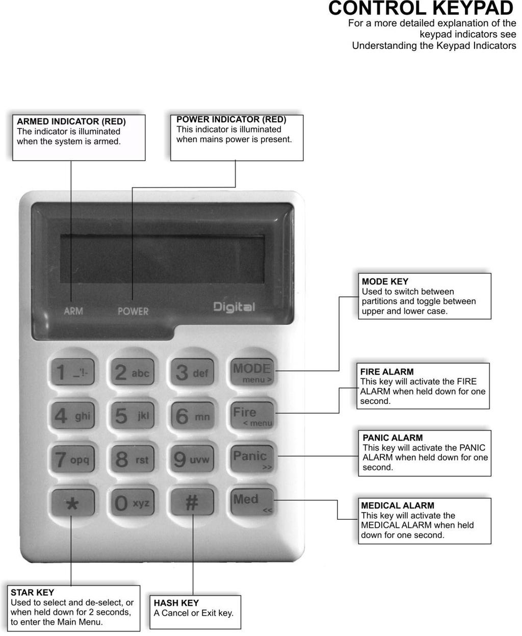
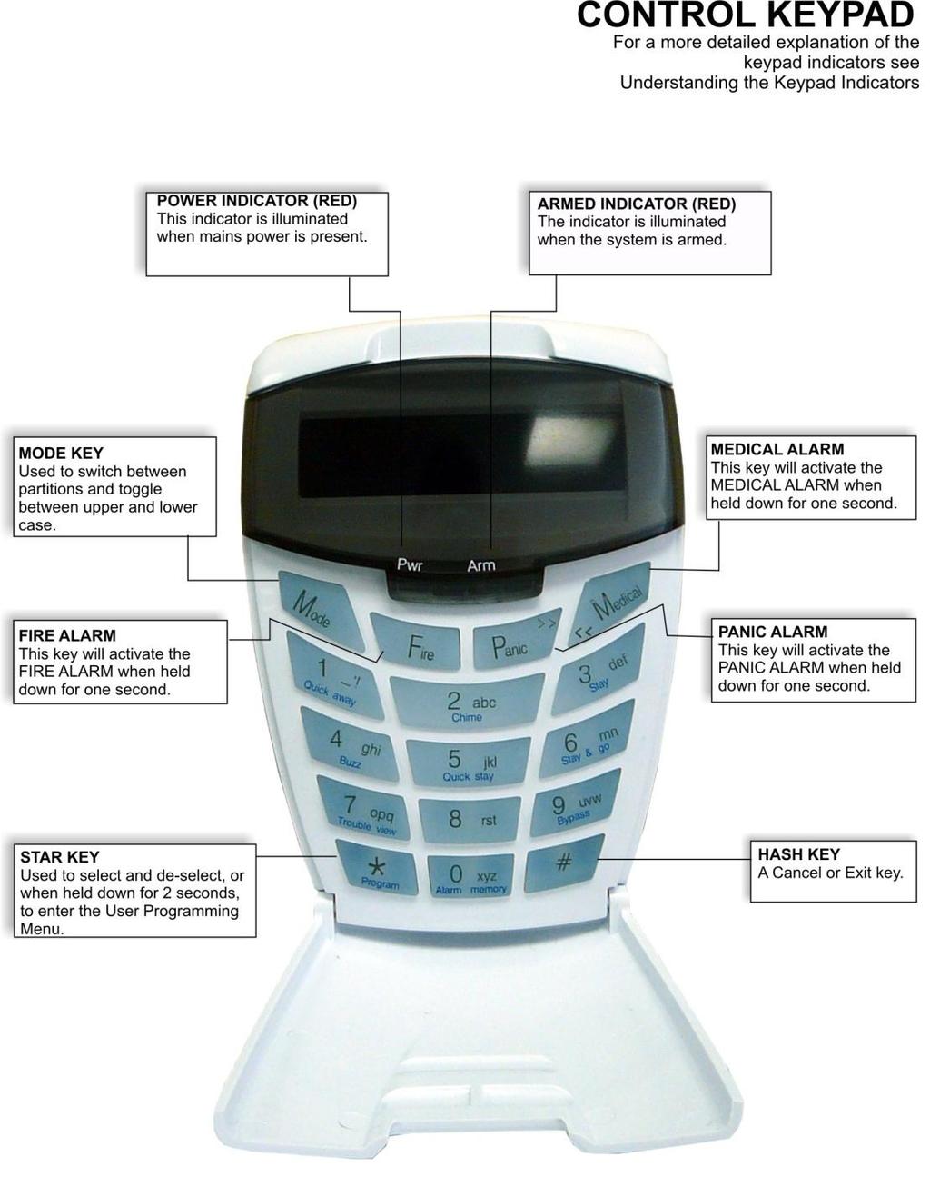
8 1. Introduction to the IDS LCD Digital Keypad Your installer has selected one of the finest alarm systems available for your installation and has custom programmed the system features to meet your specific requirements. The elegant and user friendly LCD Keypad will allow you easy access to your security system's functions and information at the touch of a button. The 32 character screen will display menus and messages to guide you through the system's operation. Since you will communicate your instructions to your system through the keypad, please read this manual carefully, and have your installer explain basic system operation. 2. Arming the Control Panel 2.1 Away Arming How to Away Arm [#] + [USER CODE] (Leave via Entry/Exit Zone) 1. Ensure that the LCD display reads 'Ready to Arm' alongside the partition number being armed. If not, check that all protected doors and windows are closed and that all movement has ceased in areas covered by motion detectors. If necessary, bypass any required zones and close the front door. 2. Press the [#] key. 3. Enter a valid [USER CODE]. If an incorrect code is entered, the keypad buzzer will beep three times. In the event of an error press, the [#] key and re-enter the code. 4. The ARM indicator will come on and the keypad buzzer will sound for the duration of the exit delay. The LCD screen will read 'Exit Delay' alongside the partition number which is being armed. Any bypassed zones will be displayed on the LCD display as solid text. Any violated zones will be displayed on the LCD display as flashing text. To scroll through zones which have been bypassed or violated use the [PANIC] and [MED] keys. 5. Leave only via a designated exit route. The panel will away arm at the end of the exit delay. 6. Once the panel has armed the LCD display will read 'Armed' alongside the partition that has been armed Quick Away Arm - Shortcut Key (Hold down the [1] key until the keypad buzzer sounds) If this function is enabled, it is possible to AWAY arm by simply holding down the [1] key. The LCD display will read 'Exit delay' alongside the partition number being armed. The keypad buzzer sounds and the arming process begins. NOTE: 8
9 If the partition is already STAY armed, this key will initialize AWAY arming. It is therefore possible to change directly from STAY armed to AWAY armed. 2.2 Stay Arming Stay arming allows the user to monitor selected perimeter zones and bypass interior zones. The user can remain on the premises with access to designated areas during the STAY ARM cycle. Any zone which may be violated accidentally should be programmed as a buzz zone. When violated, a buzz zone will cause the keypad buzzer to sound for thirty seconds before sounding the siren. Entering a valid user code before the siren sounds, prevents an alarm condition from being registered and will silence the keypad buzzer and prevent the siren from sounding. To provide greater flexibility the panel caters for the programming of two different STAY PROFILES. Each STAY PROFILE contains a unique combination of STAY, BUZZ and ALARM zones which cater for a particular STAY ARM requirement. The profile number is now indicated at the end of the top line after the armed partition on the LCD Keypad when the panel is stay armed. Example: PROFILE 1 might be used when the family goes to bed in the evening. In this profile, some interior zones may be programmed as alarm zones or buzz zones, whereas PROFILE 2 is utilised while watching television when all interior zones would be bypassed. (See 9.1 How to Select a Stay Profile.) How to Stay Arm [#] + [USER CODE] (Do not leave premises) 1. Select the required STAY PROFILE. (See Section 8.1) 2. Ensure that the LCD display reads 'Ready to arm' alongside the partition number being armed. If not, check that all protected doors and windows are closed and that all movement has ceased in the areas covered by motion detectors. 3. Press the [#] key. 4. Enter a valid [USER CODE]. If an incorrect code is entered, the keypad will give an error beep. In the event of an error press the [#] key and re-enter the [USER CODE]. 5. DO NOT violate the Entry/Exit zone (normally the front door). If the Entry/Exit zone is violated the system will arm in the AWAY mode. 6. The LCD Keypad will read 'Exit Delay', the ARM indicator will come on and the keypad buzzer will sound for the duration of the exit delay. 7. When the panel arms, any STAY zones will be automatically bypassed. These are displayed on the LCD Display as solid text. Any violated zones will be displayed on the LCD Display as flashing text. To scroll through zones which have been bypassed or violated use the [PANIC] and [MED] keys. 8. Ensure that you enter only those areas that are bypassed Quick Stay Arm - Shortcut Key (Hold down the [5] key for 2 seconds until the keypad buzzer sounds) It is possible to STAY arm by holding down the [5] key until the keypad buzzer sounds. The panel will immediately arm into the stay mode without any exit delay. Holding the [5] key again will toggle between the 2 stay profiles. 9
10 The LCD display will read 'Partial Arm' and will indicate any zones which have been bypassed. One is able to scroll through the list of bypassed, as well as violated, zones by using the [PANIC] and [MED] keys. 2.3 How to Stay Arm and Go (Hold down the [6] key for two seconds until the keypad buzzer sounds) This is a single key arm function, which allows the user to STAY arm and leave the premises. If a partition is already stay armed, holding down the [6] key initiates an exit delay, thus allowing the user to leave the premises without disarming. At the end of the exit delay, the partition will re-arm in the same stay profile it was armed in before the [6] key was held down. 1. Make sure all zones are clear. Hold down the [6] key until the keypad buzzer sounds. The LCD screen display will read 'Exit Delay' alongside the partition number being armed. Any zones that have been bypassed will be displayed on the LCD Display as solid text. Any zones that are violated will be displayed on the LCD Display as flashing text. Use the [PANIC] and [MED] keys to scroll through zones which have been bypassed or violated. The keypad buzzer will sound for the duration of the exit delay. Only leave via a designated exit route. 2. At the end of the exit delay, the ARM indicator will come on and the display will read 'Stay Arm'. All stay zones will be bypassed. 2.4 Key-Switch or Remote Arming (If fitted) 1. Ensure that the LCD display reads 'Ready to arm' before leaving. 2. Leave and close the door (remembering to lock!) 3. Activate the remote or the key-switch. A remote can be used to Stay Arm or Away Arm. 4. The alarm will arm in the away mode. NOTE: If a remote control is used it is advisable to have the siren toot on arm function enabled. This provides verification that the system has armed. 2.5 Auto Arming The panel may be programmed to arm automatically at a preprogrammed time. Should the premises be occupied at the time of auto arming, a valid [USER CODE] entered during the pre-arm delay will terminate the arming sequence. The pre-arm delay is signalled by an exit beep. 3. Disarming the Control Panel 3.1 How to Disarm with a User Code [#] + [USER CODE] To disarm the system, enter [#] followed by a valid [USER CODE]. 1. Enter the premises through a designated entry route. Entering via any other route will cause an alarm. 10
11 2. As soon as the Entry/Exit zone is violated, the entry delay will begin. The keypad buzzer will sound for the duration of the entry period. The above 2 points only apply if the premises are away armed. 3. Press the [#] key and enter a valid [USER CODE]. If an error beep occurs, press the [#] key and re-enter the user code. 4. Once the system disarms, the ARM indicator will turn off and the keypad buzzer will stop sounding. 5. If no valid user code has been entered prior to the expiry of the entry delay period an alarm condition will be registered. 6. If the entry period is too short, have your installer change the entry delay period. NOTE: If a strobe (or flashing light) has been installed and an alarm condition is registered, the strobe will continue flashing after the siren has stopped sounding. Entering a valid [USER CODE] will cancel the strobe. 3.2 How to Disarm using a Key-Switch or Remote 1. Activate the remote or key-switch. 2. The system will disarm and the remote indicator (if installed) will turn off. If the siren toot on disarm option is enabled, the siren will provide a double toot when the panel is disarmed. 4. Bypassing Zones The term BYPASS is used to describe a zone which has been deactivated; i.e. violation of a bypassed zone is ignored and will not cause an alarm condition. Once the system is armed, it is not possible to bypass zones. All bypassed zones will be automatically cancelled each time the panel is disarmed and must be re-bypassed before the next arming. 4.1 How to Bypass a Zone Hold down [9] + [ZONE NUMBER] + [*] + [#] 1. Ensure the panel is not armed. 2. To enter bypass mode, hold down the [9] key for two seconds until the keypad buzzer sounds and all LED's are off. 3. The LCD display reads 'Bypassed'. Using the [PANIC] and [MED] keys, one is able to scroll through the zones. Alternatively press the number of the zone you wish to bypass e.g. the [2] key if you wish to bypass zone 2, then press the [*] key. 4. [Y] indicates that the zone has been bypassed, whilst [N] indicates that the zone has not been bypassed. 5. Repeat step 3 to bypass other zones. 6. Press the [#] key to exit the bypass mode. NOTE: Panic zones cannot be bypassed. 11
12 4.2 How to Un-Bypass a Zone Hold down [9] + [ZONE NUMBER] + [*] + [#] 1. Enter bypass mode by holding down the [9] key until the keypad buzzer sounds. The power and arm LED's will be off. All zones will be displayed on the screen with either a [Y] or a [N] alongside the zone. 2. [Y] indicates that the zone has been bypassed, whilst [N] indicates that the zone has not been bypassed. 3. Press the number corresponding to the currently bypassed zone, then press the [*] key. Alternatively use the [PANIC] or [MED] keys to scroll through the zones. 4. Press the [#] key to exit User Program Mode. 5. Emergency Alarms 5.1 Fire Alarms [F] (Hold down the [F] key for two seconds until the keypad buzzer sounds) If the [F] key is pressed until the keypad beeps (approximately 2 seconds) a FIRE ALARM condition will be activated. The Display reads 'Alarm!' alongside the relevant partition. The FIRE ALARM CONDITION may also be triggered by a smoke detector connected to an appropriately programmed zone. The siren will sound on and off repeatedly if programmed and the FIRE REPORTING CODE will be transmitted to the monitoring company. To silence the siren enter a valid [USER CODE]. 5.2 Panic Alarms [P] (Hold down the [P] key for two seconds until the keypad buzzer sounds) If the [P] key is pressed until the keypad beeps (approximately 2 seconds) a PANIC ALARM condition will be activated. The Display reads 'Alarm!' alongside the relevant partition number. A PANIC ALARM may also be activated using any FIXED PANIC button or a REMOTE PANIC button (if installed). If the audible panic option has been selected, the siren will sound. A PANIC ALARM will be transmitted to the monitoring company. To silence the siren, enter a valid [USER CODE]. Press the [P] key only in an emergency situation which requires response by emergency personnel. 12
13 5.3 Medical Alarms [M] (Hold down the [M] key for two seconds until the keypad buzzer sounds) If the [M] key is pressed until the keypad beeps (approximately 2 seconds) a MEDICAL ALARM condition will be activated. The keypad buzzer will beep 5 times. A medical reporting code will be reported to the monitoring company. 5.4 Duress Alarms [#] + [DURESS CODE] This is a special user code that should only be used in the unique situation where an intruder forces one to disarm the system under duress. When a [DURESS CODE] is entered, the control panel disarms. A Duress Alarm Code (if programmed) will be reported to the monitoring company. It is advisable to choose a Duress code which can be easily remembered by all family (or staff) members. 6. Alarm Memory The Alarm Memory displays any zones which were tampered, violated, or bypassed during the last arm cycle. A flashing ARM indicator notifies the user of an Alarm Memory condition. To view the Alarm Memory, disarm the panel and continue as follows: [0] (Hold down the [0] key for two seconds until the keypad buzzer sounds) 1. Hold down [0] until the keypad buzzer sounds. 2. The ARM and POWER indicators will turn off and the keypad buzzer will sound briefly. 3. Use the [MED] or [PANIC] keys to scroll through the zones violated during the last armed period. 4. Press 2 to display zones which were bypassed. 5. Press 3 to display which zones were tampered. 6. Press 1 to return to violated zones. 7. The Alarm Memory is erased at the beginning of each arm cycle. 7. Zone Options 7.1 Changing a Zone Name Table 1 : Alarm Panel Zones Alarm Panel Zones Sub-location IDS
14 IDS IDS For detailed programming instructions, please see the installation manual provided with your Alarm Panel. 1. Press [#] + [INSTALLER CODE] + [*]. If the default installer code is four digits it will be [9999], if it is six digits, it will be [999999]. 2. Enter the [LOCATION] as per table 1 above followed by the [*] key. 3. Enter the [SUB-LOCATION 12] followed by the [*] key. 4. Edit the Zone Name. Notes on Editing a Zone Name Use the [MODE] key to toggle between upper and lower case. Use the [1] key to display a 1, to create a space or to display the following punctuation marks : '! - Use the [PANIC] key to scroll to the right. Use the [MED] key to scroll to the left. Pressing a key once will display the first letter displayed on the key. Pressing a key twice displays the second letter on the key etc. Numerics are displayed after all available letters have been displayed i.e. to display a 2, press the relevant key four times. If you wish to use a different letter on the same key press the key the required number of times to display the relevant letter, pause for one second. Once the cursor has advanced, you may begin entering the next letter. 8. User Codes Each of the IDS Alarm Panels has a certain number of programmable user codes as displayed in Table 2 below. By default User Code 1 is the Master User Code which contains a pre-programmed 4 digit code of The number of partitions which can be programmed by your programmer also varies for the different IDS Alarm Panels. A partition is a group of zones which may be armed and disarmed independently without affecting zones or users assigned to other partitions. I.e. a guest cottage appended to a main house may be partition 2. The main house being partition 1. NOTE: User codes may be 4 (default) or 6 digits long. This is a programmable feature. Check with your installer to verify which option has been programmed. Table 2 : Alarm Panel Features Alarm Panel No. of User Codes No. of Partitions IDS IDS IDS
15 8.1 Adding, Deleting and Editing User Codes Hold [*] + [MASTER USER CODE] + [*] + [PROGRAMMABLE OPTION] + [*] All IDS Alarm Panels utilise a user-friendly programmable interface which allows the user to add, modify, or delete user codes. See Table 3 for a summary of programmable options. The programmable interface is accessed by entering the USER PROGRAMMING MODE. Table 3 : User Programming Options Options Summary of Programmable Options Option 0 Allows for the addition of new user codes. x x x Option 1 Allows editing of the user name displayed by LCD keypads. x x x This menu is only applicable if LCD keypads are installed. Option 2 Allows editing of a selected user code. Note that the user x x x code properties are not edited, only the user code itself. Option 3 Allows viewing of the user code slot number for a selected x x x code. Option 4 Allows editing of the user code properties for a selected x x x user code. This is a bitmapped menu. Option 5 Allows the allocation of a selected user code to a x x x designated partition(s). This is a bitmapped menu. Option 6 Assign User Code to Doors (bitmapped) x Option 7 Assign a User Code to a Schedule x Option 8 Allows a remote to be assigned to a specific user x x x Option 9 Allows a user to be deleted x x x Option 10 Allows the deletion of a user code using the user code slot x x x number. Option 11 Allows viewing of a user name if the slot number is known. x x x Option 12 Add User by Slot Number x x NB: Text prompts displayed on LCD Keypads connected to the IDS 1224 and IDS 1632 are considerably more detailed than text prompts displayed on the IDS 816 Alarm Panel. 8.2 How to Enter the User Program Mode 1. Ensure that the panel is not armed. 2. Hold down the [*] key until the keypad buzzer sounds. The ARM indicator will flash. 3. The LCD prompt reads 'Enter Master Code'. The factory default is [1234]. Should the [MASTER USER CODE] be set to six digits it will be [123456] by default. 4. After entering the [MASTER USER CODE], press the [*] key. A valid entry will be confirmed by a long beep. If an invalid [MASTER USER CODE] was entered, the keypad buzzer will give an error beep (3 short beeps). If steps 1-4 are performed correctly: 5. IDS 816 Panel The LCD display will prompt for a 'Menu Option'. 15
16 IDS 1632 & IDS 1224 Panels The first menu option - Menu Option 0 - 'Add User' is displayed by default. 6. Select a programmable option from Table 1. In the case of the IDS 1632 and IDS 1224, one may use the [PANIC] or [MED] keys to scroll through the menu options. 7. Confirm the entry by pressing the [*] key. A valid entry is confirmed by a long beep. An invalid entry will be signalled by means of an error beep (3 short beeps). If an error beep occurs, press the [#] key to clear all previous entries, and repeat steps 2 6 Example: To add a new user code, enter User Program Mode by completing steps 2-5 as listed above. In the case of the IDS 816 when prompted to enter a 'Menu Option', enter a value of [0] (See table 1) followed by [*]. In the case of the IDS 1632 and the IDS 1224, Menu Option 0 will be displayed on the LCD screen by default. Press the [*] to confirm your entry. For all panels, once prompted to 'Enter a User Code', input a [NEW USER CODE] followed by the [*] key. Once the user code is programmed, enter the next code followed by [*]. To exit the program mode press the [#] key. For a full list of options, refer to Table 2. Programming of these options is explained below. 8.3 Explanation of Programmable Options Option 0 - Add a New User Code Hold [*] + [Master Code] + [*] + [0] + [*] + [New Code] + [*] 1. Enter the User Program Mode as per steps 1-4 of (8.2). 2. IDS 816 Panel When prompted for the 'Menu Option' press the [0] key followed by the [*] key to select programmable option 0. IDS 1632 & IDS 1224 Panels Menu option 0 - 'Add User' is displayed on the LCD Screen by default. As this is the programmable option you require, press the [*] key to confirm your entry. 3. The ARM key flashes and the LCD prompt reads 'Enter User Code'. 4. Enter the [NEW USER CODE] followed by the [*] key to confirm the entry. A valid entry is confirmed by a long beep. An invalid entry will be signalled by means of an error beep (3 short beeps). If an error beep occurs, press the [#] key to clear all previous entries and repeat steps Further codes can be added by repeating step 4 above. When a user code is added, it is stored in the first available user slot. 6. Press the [#] key to exit the User Program Mode Option 1 - Edit a User Name Hold [*] + [Master Code] + [*] + [1] + [*] + [User Code] + [*] 1. Enter the User Program Mode as per steps 1-4 of (8.2). 2. IDS 816 Panel When prompted for the 'Menu Option' press the [1] key followed by the [*] key to select programmable option 1. IDS 1632 & IDS 1224 Panels Menu option 0 - 'Add User' is displayed on the LCD Screen by default. To select menu option 1 - 'Edit Name', press the [1] key followed by the [*] key or alternatively use the [PANIC] or [MED] keys to scroll through the list of programmable options until you reach Menu Option 1 and press the [*] key to confirm your selection. 16
17 3. The ARM indicator flashes and the LCD prompt reads ' Enter User Code'. 4. Enter the [USER CODE] that you wish to edit. User Names are displayed as the User Slot Number by default. Edit the User Slot Number so that it reads the correct User Name. (See Notes on Editing a User Name). 5. To confirm the entry press [*]. 6. Further names may be edited by repeating steps 4-6 above. 7. Press the [#] key to exit the User Program Mode. Notes on Editing a User Name Use the [MODE] key to toggle between upper and lower case. Use the [1] key to display a 1, to create a space or to display the following punctuation marks : '! - Use the [PANIC] key to scroll to the right. Use the [MED] key to scroll to the left. Pressing a key once will display the first letter displayed on the key. Pressing a key twice displays the second letter on the key etc. Numerics are displayed after all available letters have been displayed i.e. to display a 2, press the relevant key four times. If you wish to use a different letter on the same key press the key the required number of times to display the relevant letter, pause for one second. Once the cursor has advanced, you may begin entering the next letter. The cursor will advance instantly if one presses another key. Example: You wish to change [USER 1] to read Brad. 1. To type in a (B), press the [2] key twice ( B is the second letter displayed on the key). 2. Text is defaulted to Upper case. Press the [MODE] key for lower case. Upper case text is indicated by a thin flashing cursor, whilst lowercase text is indicated by a thicker flashing cursor. 3. To type in an (r) press the [8] key once ( r is the first letter displayed on the key). 4. To type in an (a) press the [2] key once ('a' is the first letter displayed on the key). 5. To type in the letter (d) press the [3] key once (d is the first letter displayed on the key). 6. To confirm your entry press the [*] key once Option 2 - Edit a Selected User Code Hold [*] + [Master Code] + [*] + [2] + [*] + [Old Code] + [*] + [New Code] + [*] 1. Enter the User Program Mode as per steps 1-4 of (8.2). 2. IDS 816 Panel When prompted for the 'Menu Option' press the [2] key followed by the [*] key to select programmable option 2. IDS 1632 & IDS 1224 Panels Menu option 0 - 'Add User' is displayed on the LCD Screen by default. To select menu option 2 - 'Edit Name', press the [2] key or alternatively use the [PANIC] or [MED] keys to scroll through the list of programmable options until you reach Menu Option 2. Press the [*] key to confirm your selection. 3. The ARM indicator will flash and the LCD prompt reads 'Enter User Code'. Enter the [USER CODE] you wish to edit. 4. Alongside the Data prompt, enter the [NEW CODE]. To move the cursor within the [NEW CODE] use the [PANIC] or [MED] keys. 5. To confirm your entry press the [*] key. 6. The ARM indicator will flash. 17
18 7. To edit other codes repeat steps Press the [#] key to exit the User Program Mode Option 3 - View a User Code Slot Number Hold [*] + [Master Code] + [*] + [3] + [*] + [User Code] + [*] 1. Enter the User Program Mode as per steps 1-4 of (8.2). 2. IDS 816 Panel When prompted for the 'Menu Option' press the [3] key followed by the [*] key to select programmable option 3. IDS 1632 & IDS 1224 Panels Menu option 0 - 'Add User' is displayed on the LCD Screen by default. To select menu option 3 - 'View Slot num', press the [3] key or alternatively use the [PANIC] or [MED] keys to scroll through the list of programmable options until you reach Menu Option 3. Press the [*] key to confirm your selection. 3. The ARM indictor will flash and the LCD prompt reads 'Enter User Code'. 4. Once you have entered the [USER CODE] followed by the [*] key the Slot num is displayed alongside the Data prompt. 5. To view other Slot numbers press the [*] key and repeat steps Press the [#] key to exit the User Program Mode Option 4 - User Code Properties Hold [*] + [Master Code] + [*] + [4] + [*] + [User Code] + [*] + [Property Number] + [*] 1. Enter the User Program Mode as per steps 1-4 of (8.2). 2. IDS 816 Panel When prompted for the 'Menu Option' press the [4] key followed by the [*] key to select programmable option 4. IDS 1632 & IDS 1224 Panels Menu option 0 - 'Add User' is displayed on the LCD Screen by default. To select menu option 4 - 'User Options', press the [4] key or alternatively use the [PANIC] or [MED] keys to scroll through the list of programmable options until you reach Menu Option 4. Press the [*] key to confirm your selection. 3. The ARM indictor will flash and the LCD prompt reads 'Enter User Code'. 4. Once you have entered the [USER CODE], followed by the [*] key select a User Code property by pressing the key which corresponds to that property. In the case of the IDS 1632 and the IDS 1224, one may use the [PANIC] or [MED] keys to scroll through the User Options which can be assigned to a user. 5. Pressing the [*] key toggles between [Y] and [N] for the selected user option. 6. Repeat steps 4 & 5 until the desired properties have been programmed. 7. To edit another User Code's properties, press the [#] key and repeat steps Press the [#] key twice to exit user program mode. Example: To enable a User Code to function as a duress code, when prompted for the Option press the [2] key followed by the [*] key. 18
19 Table 4 : User Code Properties Zone LED Property Master User X X X 2 Duress Code X X X 3 Arm to Disarm Code [Maid s Code] X X X 4 Group Arm (Global Arm /Disarm for 816) X X X 5 Group Disarm X X 6 Arm Code X X 7 Disarm Code X X 8 Report User Open Close X X 9 User Phone in Access X X 10 Report User Access X 11 Enable Anti-pass back for User X 12 Fire Code X Explanation of User Code Properties Master User When assigned to a user, this property allows the user to act as a Master User Duress Code This is a special 4 (default) or 6 digit user code (check the code length with your installer) and should only be used in the unique situation where an intruder forces one to disarm the system "under duress". When the [DURESS CODE] is entered, the control panel disarms normally - however a DURESS REPORTING CODE is transmitted to the monitoring company to inform them that you have been forced to disarm the control panel by an intruder. It is advisable to choose a code that can be easily remembered by all family (or staff) members Maid's Code This code may be used to limit access to the premises. A maid's code will only disarm the system if the same code was used for arming. If armed with a code other than this code, the system will view an attempt to disarm using a maid's code as an invalid entry. Any valid user code will disarm the system if it has been armed with a maid s code Global Arm / Disarm Code (Not applicable to the IDS 1224 & IDS 1632) This code when entered will either arm or disarm the partitions assigned to that user depending on their status. If both partitions are disarmed, entering a global code will arm both partitions. If both partitions are armed, entering a global code will disarm them. In the case where one partition is armed and the other 19
20 disarmed, entering a global code at the keypad of the armed partition will disarm that partition and entering a global code at the keypad of the disarmed partition will arm that partition Group Arm (Not applicable to the IDS 816) This code when entered will arm the partitions assigned to the user depending on their status. If all partitions are disarmed, entering a group code will arm all of the assigned partitions. In a case where some partitions are armed and others disarmed, entering this group code at the keypad of the disarmed partition will arm the disarmed partitions only Group Disarm (Not applicable to the IDS 816) This code when entered will disarm the partitions assigned to the user depending on their status. If all partitions are armed, entering a group code will disarm all of the assigned partitions. In a case where some partitions are disarmed and others armed, entering this group code at the keypad of the armed partition will disarm the armed partitions only Report User Open Close (Not applicable to the IDS 816) This option enables reporting of a pre-programmed reporting code when a partition assigned to this user is armed / disarmed User Phone in Access (Not applicable to the IDS 816) If enabled this option allows the user to arm or disarm a panel using a DTMF telephone. If the installer selects the full menu, the user will be able to bypass zones, open doors and toggle outputs Report User Access (Not applicable to the IDS 1224 & IDS 816) This option enables reporting of a pre-programmed reporting code when a user opens a door assigned to them Enable Anti-pass back for User (Not applicable to the IDS 1224 & IDS 816) If enabled this option does not allow a user to enter an assigned area for a second time, if the user has not exited the assigned area after the previous entry. 20
21 Fire Code (Not applicable to the IDS 1224 & IDS 816) If enabled,this option allows reporting of a Fire Code. In the event that this code is reported, all fire doors will be automatically opened Option 5 - Assign User Code to Partitions Hold [*] + [Master Code] + [*] + [5] + [*] + [User Code] + [*] + [Partition Number] + [*] 1. Enter the User Program Mode as per steps 1-4 of (8.2). 2. IDS 816 Panel When prompted for the 'Menu Option' press the [5] key followed by the [*] key to select programmable option 5. IDS 1632 & IDS 1224 Panels Menu option 0 - 'Add User' is displayed on the LCD Screen by default. To select menu option 5 - 'Partitions', press the [5] key or alternatively use the [PANIC] or [MED] keys to scroll through the list of programmable options until you reach Menu Option 5. Press the [*] key to confirm your selection. 3. The ARM indictor will flash and the LCD prompt reads 'Enter User Code'. 4. When prompted for the 'User Code enter the [USER CODE] followed by the [*] key. 5. The partitions to which the [USER CODE] is assigned are indicated by Options 1 or 2 in the case of the IDS 816, Options 1-4 in the case of the IDS 1224 or Options 1-8 in the case of the IDS If the user is assigned to partition 1, there will be a [Y] next to Option 1 and the user can thus arm and disarm partition 1. If the user is assigned to partition 4, there will be a [Y] next to Option 4. It is possible to program codes to arm / disarm any combination of the available partitions. 6. To select which partitions the [USER CODE] may arm or disarm, toggle options by entering the [PARTITION NUMBER] followed by the [*] key. One may also use the [PANIC] and [MED] keys to scroll through the partitions. 7. Repeat step 6 until the User Code has been assigned to the correct partition(s). 8. Press the [#] key to edit another User Code's partitions. 9. Press [#] twice to exit program mode Option 6 - Assign User Code to Doors (Not applicable to the IDS 1224 & IDS 816) Hold [*] + [Master Code] + [*] + [6] + [*] + [User Code] + [*] + [Door Number] + [*] 1. Enter the User Program Mode as per steps 1-4 of (8.2). 2. Menu option 0 - 'Add User' is displayed on the LCD Screen by default. To select menu option 6 - 'Doors', press the [6] key or alternatively use the [PANIC] or [MED] keys to scroll through the list of programmable options until you reach Menu Option To select programmable option 6, press the [*] key. The ARM LED will flash. 4. When prompted for the 'User Code' enter the [USER CODE] followed by the [*] key. 5. The doors to which the [USER CODE] can be assigned are indicated by Options To scroll through the list of options use the [PANIC] or [MED] keys. Use the [*] key to toggle between [Y] and [N]. Alternatively press the door number you wish to select. 21
22 Example: If a user is assigned to door 1, there will be a [Y] next to Option 1 and the user can thus open door 1. If the user is assigned to door 14 there will be a [Y] next to Option 14. It is possible to program codes to open any combination of the available doors. 6. Repeat step 5 until the User Code has been assigned to the correct doors. 7. Press the [#] key to edit another User Code's doors and repeat steps 4 & Press [#] twice to exit program mode Option 7 - Assign a User Code to a Schedule (Not applicable to the IDS 1224 & IDS 816) Hold [*] + [Master Code] + [*] + [7] + [*] + [User Code] + [*] + [Schedule Number] + [*] 1. Enter the User Program Mode as per steps 1-4 of (8.2). 2. Menu option 0 - 'Add User' is displayed on the LCD Screen by default. To select menu option 7 - 'Schedule', press the [7] key or alternatively use the [PANIC] or [MED] keys to scroll through the list of programmable options until you reach Menu Option To select programmable option 7, press the [*] key. The ARM LED will flash. 4. When prompted for the 'User Code enter the [USER CODE] followed by the [*] key. 5. Three schedule options exist. Schedule options are displayed next to the data prompt. If a user is assigned to Schedule 0, the user may arm / disarm the premises at any given time. Users assigned to Schedule 1 are allowed to arm / disarm the area only during the specified programmed schedule times. The same applies to those users assigned to Schedule To select which schedule the [USER CODE] may be assigned to, press the relevant keypad key followed by the [*] key. 7. Press [*] key to assign another user to a schedule and repeat steps 4 & Press [#] key to exit User Program Mode Option 8 - Adding User Remotes Hold [*] + [Master Code] + [*] + [8] + [*] + [User Code] + [*] 1. Enter the User Program Mode as per steps 1-4 of (8.2). 2. IDS 816 Panel When prompted for the 'Menu Option' press the [8] key followed by the [*] key to select programmable option 8. IDS 1632 & IDS 1224 Panels Menu option 0 - 'Add User' is displayed on the LCD Screen by default. To select menu option 8 - 'Assign Remote', press the [8] key or alternatively use the [PANIC] or [MED] keys to scroll through the list of programmable options until you reach Menu Option 8. Press the [*] to confirm your selection. 3. The ARM indicator flashes and the LCD prompt reads 'Enter User Code'. 4. Enter the [USER CODE] followed by the [*] key. 5. Press any button on the new remote. This will assign the new remote to the user code as entered in Step 4. Press [*] to store the added remote. 6. To add additional remotes, repeat steps 4 & 5 or press the [#] key to exit User Program Mode. 22
23 Option 9 - Delete User Code (Code known) Hold [*] + [Master Code] + [*] + [9] + [*] + [User Code to be deleted] + [*] 1. Enter the User Program Mode as per steps 1-4 of (8.2). 2. IDS 816 Panel When prompted for the 'Menu Option' press the [9] key followed by the [*] key to select programmable option 9. IDS 1632 & IDS 1224 Panels Menu option 0 - 'Add User' is displayed on the LCD Screen by default. To select menu option 9 - 'Default Code', press the [9] key or alternatively use the [PANIC] or [MED] keys to scroll through the list of programmable options until you reach Menu Option 9. Press the [*] to confirm your selection. 3. The ARM LED will flash. 4. When prompted for the 'User Code' enter the [USER CODE] to be deleted followed by the [*] key. 'Deleting' the code in slot one will reprogram it to Further codes may be deleted by repeating Step 4 above. 6. After deleting the final code, press the [#] key to exit User Program Mode Option 10 - Delete a User Code ("Slot" known) Hold [*] + [Master Code] + [*] + [1] + [0] + [*] + [User Slot] + [*] 1. Enter the User Program Mode as per steps 1-4 of (8.2). 2. IDS 816 Panel When prompted for the 'Menu Option' press the [1] key followed by the [0] key to select programmable option 10. IDS 1632 & IDS 1224 Panels Menu option 0 - 'Add User' is displayed on the LCD Screen by default. To select menu option 10 - 'Default Slot', press the [1] key followed by the [0] or alternatively use the [PANIC] or [MED] keys to scroll through the list of programmable options until you reach Menu Option 10. Press the [*] to confirm your selection. 3. The ARM indicator flashes and the LCD prompt reads 'Enter User Slot'. 4. When prompted for the 'User Slot' enter the [SLOT NUMBER] for the User Code you wish to delete followed by the [*] key. 5. Further User Codes may be deleted by repeating Step After deleting the final code, press the [#] key to exit User Program Mode Option 11 - Viewing a User Name Hold [*] + [Master Code] + [*] + [1] + [1] + [*] + [User Slot] + [*] 1. Enter the User Program Mode as per steps 1-4 of (8.2). 2. IDS 816 Panel When prompted for the 'Menu Option' press the [1] key followed by the [1] key to select programmable option 11. IDS 1632 & IDS 1224 Panels Menu option 0 - 'Add User' is displayed on the LCD Screen by default. To select menu option 11 - 'Slot Name', press the [1] key followed by the [1] or alternatively use the [PANIC] or [MED] keys 23
24 to scroll through the list of programmable options until you reach menu option 11. Press the [*] to confirm your selection Enter the [USER SLOT] followed by the [*] key. 4. The USER NAME will be displayed. Default names are displayed as the SLOT NUMBER (i.e. If the SLOT NUMBER has not been edited as per Option 1) 5. To view another USER NAME press [*] and repeat steps 3 & Press [#] to exit User Program Mode Option 12 - Add User Slot (Not applicable to the IDS 816) Hold [*] + [Master Code] + [*] + [1] + [2] + [*] + [Slot Number] + [*] + [New User Code]+[*] 1. Enter the User Program Mode as per steps 1-4 of (8.2). 2. Menu option 0 will be displayed on the LCD Display by default. To select menu option 12 - 'Add User Slot' press the [1] key followed by the[2] key or alternatively use the [PANIC] or [MED] keys to scroll through the list of programmable options until you reach menu option Press the [*] to confirm your selection. 4. Enter the [SLOT NUMBER] followed by the [*] key. 5. Enter the [NEW USER CODE] followed by the [*] key. 6. To add additional user codes repeat steps 4 & Press [#] to exit User Program Mode. 9. "Stay Zones" Stay zones are those zones which are bypassed automatically when the system is "STAY ARMED". To avoid triggering the alarm, zones such as bedrooms which are protected by Passive Infra-Red (PIR) detectors or windows which may be opened, must be bypassed when "staying at home". Stay zones need only be programmed once. Each time the system is armed in the Stay Mode the pre-selected stay zones will be bypassed automatically. The panel allows for two unique STAY PROFILES to be stored. A STAY PROFILE stores a preselected combination of STAY and BUZZ zones to suit a specific STAY ARM requirement. If a partition is stay armed using Profile 1, it is possible to toggle the panel arm status directly to stay arm profile 2 by holding the [5] key for two seconds. STAY and BUZZ zones can be programmed for each profile once the profile has been selected. See section 9 & How to Select a Stay Profile [#] + [MODE] + [2] + [*] + [PROFILE NUMBER] + [*] 1. Press the [#] key to clear any previous entries. 2. Hold [MODE] down for one second until the keypad beeps twice. 3. When prompted for the 'Mode' press the [2] key followed by the [*] key. 4. When prompted to 'Select Profile' press [1] or [2] for the required profile. 5. Press [*] to enter. The buzzer will give a long beep. 6. Program STAY and BUZZ zones for the profile or ARM the profile (See sections 10 and 11). 9.2 How to Program Stay Zones HOLD [3] + [ZONE NUMBER] + [*] + [#] 24
25 1. Select the required stay profile (See 9.1) 2. Hold down the [3] key until the keypad buzzer sounds. The LCD keypad will indicate that the panel is in Stay mode alongside the partition number. 3. Press the [NUMBER] corresponding to the zone you wish to be a STAY zone followed by the [*] key. Alternatively use the [PANIC] or [MED] keys to scroll through the zones. 4. A [Y] next to a zone number indicates that that particular zone is programmed as a stay zone. NOTE: Buzz zones will be shown by flashing indicators. (See Section 8). A Buzz zone cannot be selected as a Stay Zone. The Buzz status must be cleared first. 5. Repeat step 3 until the selection of stay zones is completed. 6. Press the [#] key to exit the stay zone programming mode. 9.3 How to Cancel Stay Zones 1. Select the required Stay Profile (See 9.1) HOLD [3] + [ZONE NUMBER] + [*] + [#] 2. Hold down the [3] key until the keypad buzzer sounds. The LCD display will indicate that the panel is in the Stay Zone programming mode. 3. Press the [NUMBER] corresponding to the STAY zone you wish to cancel followed by the [*] key. Alternatively use the [PANIC] and [MED] keys to scroll through zones. 4. A [N] next to the zone number indicates that the zone is not selected as a stay zone. 5. Repeat step 3 until all the required stay zones have been cancelled. 6. Press the [#] key to exit the stay zone programming mode. 10. Buzz Zones Violation of a buzz zone when Stay Armed will cause the keypad buzzer to sound for a period of 30 seconds during which time a valid user code must be entered. If a valid user code is not entered during this period, the system will register an alarm condition. This feature helps prevent unnecessary false alarms. NOTE: If an Entry/Exit zone is programmed as a buzz zone, violation of the Entry/Exit zone (when the panel is Stay Armed) will cause the keypad buzzer to sound for the duration of the entry delay time. This, if the panel is stay armed, allows the user to enter the premises and disarm the panel. If it is not programmed as a buzz zone, the alarm will be triggered immediately. If the panel was armed using the [6] key (Stay Arm and Go) violation of the Entry/Exit zone will always start the Entry/Exit delay How to Program Buzz Zones HOLD [4] + [ZONE NUMBER] + [*] + [#] 1. Select the required Stay Profile. (See 9.1) 2. Hold down the [4] key until the keypad buzzer sounds. The LCD Display will indicate that the keypad is in Buzz Mode. 25
26 3. Press the [NUMBER] corresponding to the zone you wish to be programmed as a Buzz zone followed by the [*] key. Alternatively use the [PANIC] or [MED] keys to scroll through the zones. 4. A [Y] next to the zone number indicates that the zone has been programmed as a Buzz zone. Flashing text indicates a Stay zone. A zone cannot be both a Buzz and Stay Zone and a Stay zone cannot be selected as a Buzz zone. 5. Repeat step 3 until all the required buzz zones are programmed. 6. Press the [#] key to exit the buzz programming mode. NOTE: A zone cannot be both a Buzz and Stay Zone. A Stay zone cannot be selected as a Buzz zone How to Cancel Buzz Zones HOLD [4] + [ZONE NUMBER] + [*] + [#] 1. Select the required Stay Profile. (See 9.1) 2. Hold down the [4] key until the keypad buzzer sounds. The LCD Display will indicate that you are in Buzz Mode. 3. Press the [NUMBER] corresponding to the Buzz zone you wish to cancel followed by the [*] key. Alternatively use the [PANIC] or [MED] keys to scroll through the zones. 4. A [N] next to the zone number indicates that the zone has not been selected as a buzz zone. 5. Repeat step 3 until all the required buzz zones have been cancelled. 6. Press the [#] key to exit the buzz zone programming mode. 11. Chime Zones The chime mode allows the user to monitor nominated zones while the system is disarmed. The keypad buzzer will sound briefly when the nominated zone is violated - the siren will NOT sound and no alarm condition will be reported. Example: If you wish to know each time someone enters or exits the front door of your office, program this zone as a chime zone, the keypad will beep each time someone opens the front door How to Program Chime Zones HOLD [2] + [ZONE NUMBER] + [*] + [#] 1. Hold down the [2] key until the keypad buzzer sounds. 2. The LCD display will indicate that you are in the chime mode. 3. To program a zone as a chime zone, press the key corresponding to that zone followed by the [*] key. The zone indicator will come on. Alternatively use the [PANIC] or [MED] keys to scroll through the zones. 4. A [Y] next to the zone number indicates that the zone has been selected as a chime zone. 5. Program any other zones you wish to select as chime zones as per step Press the [#] key to exit the chime programming mode. 26
27 11.2 How to Cancel Chime Zones HOLD [2] + [ZONE NUMBER] + [*] + [#] 1. Hold down the [2] key until the keypad buzzer sounds. 2. The LCD display will indicate that you are in chime mode. 3. To cancel any chime zones, press the key corresponding to that zone followed by the [*] key. Alternatively use the [PANIC] or [MED] keys to scroll through the zones. 4. An [N] alongside the zone number indicates that the chime zone has been cancelled. 5. Repeat step 3 until all the required chime zones have been cancelled. 6. Press the [#] key to exit the chime programming mode. 12. Viewing Trouble Conditions (Hold down the [7] key for two seconds until the keypad buzzer sounds) The user is alerted to a trouble condition via a flashing power LED. It is also possible to enable a trouble beep. If the trouble beep has been enabled, the keypad buzzer will sound to alert the user that a trouble condition has occurred. Press the [#] key to silence the buzzer. Hold down the [7] key for two seconds. The ARM LED will flash. The system will automatically exit the TROUBLE VIEWING MODE after one minute. Alternately to exit this mode press [#]. NOTE: Certain trouble conditions will only clear once the trouble condition has restored. To cancel the beeping without viewing the trouble conditions, press [#] key. Table 5 : Trouble Conditions Indicator Trouble Condition 1 AC Mains Failure 2 Failure to communicate successfully to monitoring company 3 Phone line trouble 4 Siren tamper 5 Low battery 6 Loss of Clock Timer 7 Engineer Reset 8 Box tamper 9 Keypad 12V trouble 10 Tamper on peripheral device 11 Communication loss to peripheral device 12 Loss of power to peripheral devices 13 Reserved 14 SIM PIN Error 15 GSM Modem Error 27
28 13. Changing a Partition To change partitions the keypad must be assigned to access the required partition. 1. Hold [MODE] until the keypad beeps. 2. Press [1] [*]. 3. When prompted by the display to 'Select Partition' press [partition number] [*] The keypads may be partitioned to remain in the new partition. Any value outside of these constraints will result in a key entry error occurring. Feature IDS 816 IDS 1224 IDS 1632 Partition Zone Output Doors Remote Telephone Access Please note that this section is only relevant if programmed by your installer. The IDS Alarm Panels have a secure, remote telephone interface which allows a user to arm/disarm, to bypass/un-bypass zones and to set programmable outputs via a phone line. A user accesses the remote dial-in interface by dialling the Alarm Panel using a DTMF phone. To access the remote dial-in interface, dial the Alarm Panel, and wait the number of rings programmed (the default number of rings being 15). If the fax defeat function has been enabled, dial the panel and hang up after one ring. Dial in again within 1 minute, the panel will pick up immediately and transmit handshake tones consisting of a high pitch tone for two seconds followed by a lower pitch tone for one second. Within twenty seconds of the panel transmitting the handshake tones, enter a valid user code on the DTMF enabled phone. If a user code is not entered or if the user code is invalid - the panel will release the line. If the user code is valid and telephone access has been enabled, the panel will give a single confirmation beep indicating that the user has gained access to the remote interface. If no key-presses are detected for twenty seconds once access has been gained to the remote interface the panel will release the line. Should the panel be programmed to report to your cellular telephone, entering the user code in the delay between beeps will also allow access to the remote telephone interface. If the phone in access has been setup to arm/disarm only, pressing the number of the partition allows the user to toggle the panels arm status. A single beep indicates that the partition has armed; a double beep indicates that the partition has disarmed. 3 beeps indicate that the partition is not ready to arm. If the phone in access has been set up to access the full menu, please refer to the table 5 and select the required operation. 28
Contents. 4. Disarming the Control Panel How to Disarm with a User Code How to Disarm using a Key-Switch or Remote...
 Contents 1. Introduction to the Watchguard WGAP864 LCD Digital Keypad... 6 2. Viewing Violated Zones... 6 3. Arming the Control Panel... 7 3.1 Away Arming... 7 3.1.1 How to Away Arm... 7 3.1.2 Quick Away
IDS X-Series User Manual E Issued June 2013
 1 2 Contents 1. Introduction to the IDS X-Series Panels... 6 2. Before Operating Your Alarm System... 6 3. Understanding the Keypad LEDs... 7 3.1 Viewing Data on an LED Keypad... 11 3.2 Entering Data on
IDS. Users Guide to Keypad Functions S E C U R I T Y MANUAL NO D ISSUED NOVEMBER 2002 VERSION 2.
 INHEP DIGITAL IDS S E C U R I T Y Users Guide to Keypad Functions MANUAL NO. 700-146-01D ISSUED NOVEMBER 2002 VERSION 2.17 Summary of Operation A rm/ disarm [#] + [USER CODE] Quick Quick Quick Away Arm
Important Notice. Customer Information. 2 WisDom User Manual
 User Manual Important Notice This manual is delivered subject to the following conditions and restrictions: This manual contains proprietary information belonging to RISCO Group. The information is supplied
Property of Monitronics Inc
 Enter Program 1. Master Code + 8 + 0 + 0 (Display should show 20) or Power down then back up and press * and # within 1 minute (If exiting programming you can re-enter within 1 minute by pressing * and
IDS1200 INSTALLER MANUAL. Summary of Operation 2 IDS1200 INSTALLER MANUAL - NO B ISSUED AUGUST 2002 VER 1.18
 IDS12 INSTALLER MANUAL Summary of Operation A rm/ disarm [#] + [USER CODE] Quick Away Arm Quick Stay Arm Quick Stay Arm & Go H old down [ 1] for 1 second H old down [ 5] for 1 second H old down [ 6] for
Property of Monitronics Inc
 Enter Program (Locations 034 to 410) 1. Press Program Button on main panel 2. At keypad press 9 + Program Code (9 8 7 6 5) or 1. Power down with black switch on bottom left of panel 2. Power up while holding
Created by: Alarm System Store Quick Start Guide. for Interlogix NetworX NX4, NX6 & NX8
 Quick Start Guide for Interlogix NetworX NX4, NX6 & NX8 Programming Code = 9713 Master User Code=1234 Program Mode= *8 + 9713 To exit programming hit the Exit key until you reach the home screen If this
INT-KSG Keypad Quick user s guide
 INT-KSG Keypad Quick user s guide Firmware version 1.02 int-ksg_u_en 01/13 SATEL sp. z o.o. ul. Schuberta 79 80-172 Gdańsk POLAND tel. + 48 58 320 94 00 info@satel.pl www.satel.eu WARNINGS Please read
DSC programming for the Alexor and Impassa
 DSC programming for the Alexor and Impassa THERE IS NO REASON TO BE IN ANY SECTION OF YOUR SYSTEM UNLESS IT IS ON THIS QUICK START GUIDE. If you do not see it here, please question if you should be doing
Solution 16 plus. User Guide Security System
 Solution 16 plus EN Security System Copyright Notice Unless otherwise indicated, this publication is the copyright of Bosch Security Systems Pty Ltd ( Bosch ). All rights are reserved.you may download
D1260/D1260B. Owner's Manual. Keypad
 D1260/D1260B EN Owner's Manual Keypad D1260/D1260B Owner's Manual This system includes a telephone line seizure feature. The system may be programmed to communicate with a central monitoring station to
1HWZRU;1;( Table of Contents. General Description...2. Ordering Information...2. Feature Definitions...3. Programming the LED Keypads...
 HWZRU;;( Control/Communicator Installation Manual Table of Contents General Description... Ordering Information... Feature Definitions... Programming the LED Keypads... Programming the NX-E...9 Types of
VoiceNav User Manual
 r VoiceNav User Manual 1 Table of contents Introduction 2 Drawing 3 Glossary of terms 4 Glossary of terms continued 5 Legend 5 Warranty 5 Indicators, icons and lights 6 Away arming 7 Stay arming 8 Disarming
RANGER 9000E DOWNLOADABLE CONTROL COMMUNICATOR INSTALLATION MANUAL
 RANGER 9000E DOWNLOADABLE CONTROL COMMUNICATOR INSTALLATION MANUAL TABLE OF CONTENTS GENERAL DESCRIPTION... 2 STANDARD AND OPTIONAL PARTS LIST... 2 FEATURE DEFINITIONS... 3 TERMINAL DRAWING AND SPECIAL
VISTA 12a / 48a TECHNICAL TRAINING. The Best in Security plus Everyday Convenience & Control
 VISTA 12a / 48a TECHNICAL TRAINING The Best in Security plus Everyday Convenience & Control Version #.007 7th June 2005 VISTA 12a / 48a Training Guide Index 1. Vista Family Features....... p. 3 2. Wiring
INT-KSG Keypad Quick user s guide
 INT-KSG Keypad Quick user s guide Firmware version 1.00 int-ksg_u_en 08/10 SATEL sp. z o.o. ul. Schuberta 79 80-172 Gdańsk POLAND tel. + 48 58 320 94 00 info@satel.pl www.satel.eu WARNINGS Please read
Series. NX-8-EUR Control Panel. Installation manual
 g GE Security NetworX TM Series NX-8-EUR Control Panel Installation manual NX-8-EUR Installation manual Page 2 23/12/04 CONTENTS CONTENTS...3 GENERAL INFORMATION...5 ORDERING INFORMATION...5 FEATURE DEFINITIONS...6
Property of Monitronics Inc
 Enter Program Master Code + 8 + 0 + 0 (Display should show 20) or Power down then back up and press * and # within 1 minute (If exiting programming you can re-enter within 1 minute by pressing * and #)
LCD User Station User Manual
 LCD User Station User Manual PUBLICATION INFORMATION 504A R Final Release CONTENTS 1.0 INTRODUCTION... 4 1.1 Legend... 2.2 Terminology... 2.0 OPERATION... 8 2.1 Indicator Lights... 2.2 Visual Display...
First Alert FA160C/162C Installer Notes M. Leuck
 First Alert FA160C/162C Installer Notes M. Leuck 1. Programming can only be done by 6139 Alpha keypads, standard 6128 keypad cannot be used to program zones 2. Enter programming: Master Code + 8 + 0 +
Table of Contents. Phone number configuration...15 Alarm Phone numbers, 1, 2 & Divert phone numbers 1, 2 &
 Table of Contents Introduction... 4 Warning... 5 Warranty... 5 Glossary of terms... 6 Legend... 7 Feature & Benefits... 8 1. Phone Line connection... 8 Phone Line connection, and network connection...9
ELECTRONIC ENGINEERING LTD. OLED Keypad. User s Guide. P/N: Doc Rev-A SW Ver /08/10
 ELECTRONIC ENGINEERING LTD. OLED Keypad User s Guide P/N: 7103670 Doc Rev-A SW Ver-0.65 05/08/10 Crow Limited Warranty Crow warrants this product to be free from defects in materials and workmanship under
Ademco Vista-20SE/First Alert FA-162C Program Sheet
 Enter Program 1. 4112 + 8 + 0 + 0 (Display should show 20) or Power down then back up and press * and # within 1 minute (If exiting programming you can re-enter within 1 minute by pressing * and #) Exit
DAS 250L CONTROL COMMUNICATOR INSTALLATION MANUAL
 DAS 250L CONTROL COMMUNICATOR INSTALLATION MANUAL TABLE OF CONTENTS 1. GENERAL DESCRIPTION... P.2 2. STANDARD AND OPTIONAL PARTS LIST..... P.2 3. FEATURE DEFINITIONS... P.3 4. TERMINAL DRAWING AND SPECIAL
SECURITY MODULE CG3 User Manual
 SECURITY MODULE CG3 User Manual Security system can be managed with Paradox K636, K10 LED, K32 LED and Protegus SK130 LED Control by the keypad Paradox 1. Full arming the security system (when the security
PROGRAMMING HELP GUIDE
 DIGIPLEX EVO48-192 PROGRAMMING HELP GUIDE Entering Programming Mode 1) Press and hold the [0] key 2) Enter your [Installer Code] (default-000000) 3) Enter 4-digit [section] you wish to program 4) Enter
Control Panel ICP-SOL2-P/ICP-SOL3-P. en Quick Reference Guide
 Control Panel ICP-SOL2-P/ICP-SOL3-P en Quick Reference Guide Control Panel Table of Contents en 3 Table of contents 1 Introduction 6 2 Programming 7 2.1 ICON LCD Codepad Programming 7 2.2 TEXT LCD Codepad
Solution 144 Security Systems
 Security Systems EN Security System Copyright Notice Unless otherwise indicated, this publication is the copyright of Bosch Security Systems Pty Ltd ( Bosch ). All rights are reserved.you may download
High Security and Access System EVO48 V2.1 EVO192 V2.1
 High Security and Access System EVO48 V2.1 EVO192 V2.1 Programming Guide Includes LCD Keypad Programming We hope this product performs to your complete satisfaction. Should you have any questions or comments,
SILENCING AN ALARM. When the alarm bell or siren is sounding, enter your user code or present your keyfob to your keypad.
 S Y S T E M U S E R G U I D E SILENCING AN ALARM When the alarm bell or siren is sounding, enter your user code or present your keyfob to your keypad. IS THIS A FALSE ALARM? YES NO displays. REAL ALARM
Installer Notes 4110DL/XM, Vista 10, Vista-20, Via-30PSE
 Installer Notes 4110DL/XM, Vista 10, Vista-20, Via-30PSE 1. Programming can only be done with a 6139 Alpha Keypad on Vista-10/20/30PSE models. 2. When entering programming for the first time during Installations
KarizmaPlus Intruder alarm system Operating instructions
 KarizmaPlus Intruder alarm system Operating instructions Introduction The purpose of this user guide is to describe how to operate Karizma plus system. Some of the features described in this guide may
DAYLIGHT SAVINGS TIME START/END MONTH [ 0 ]0 = Disabled; 1 = Enabled. 1 Start End
![DAYLIGHT SAVINGS TIME START/END MONTH [ 0 ]0 = Disabled; 1 = Enabled. 1 Start End](/thumbs/72/66709046.jpg "DAYLIGHT SAVINGS TIME START/END MONTH [ 0 ]0 = Disabled; 1 = Enabled. 1 Start End") RcvrAcct#: Test Date: May, ::PM SYSTEM ENTRY DELAY# [ ] = None, = secs, = secs, = secs, = secs, = secs, = mins [UL installations: The Entry Delay must be set for a maximum of seconds] ENTRY DELAY# [ ]
RcvrAcct#: Test Date: May, ::PM SYSTEM ENTRY DELAY# [ ] = None, = secs, = secs, = secs, = secs, = secs, = mins [UL installations: The Entry Delay must be set for a maximum of seconds] ENTRY DELAY# [ ]
MCM Electronics MCM Electronics MCM Electronics. The Icon Series. Installation and Programming Information. Icon 8 Version 5.0
 MCM Electronics MCM Electronics MCM Electronics The Icon Series Installation and Programming Information Icon 8 Version 5.0 TABLE OF CONTENTS 1. 2. 3. Panel Hardware Page 2 Physical Layout. Inputs. Outputs.
SUPERPLEX. User s Manual. High performance, simplified wireless home security controller. Products that work. Software Release: V2.
 SUPERPLEX User s Manual Products that work Software Release: V2.5 KE-MOBILEHQ-12- High performance, simplified wireless home security controller Thank you for purchasing this Kingdom Electronics product.
Property of Monitronics Inc
 Enter Program 1. 4112 + 8 + 0 + 0 (Display should show 20) or Power down then back up and press * and # within 1 minute (If exiting programming you can re-enter within 1 minute by pressing * and #) Exit
NX-148 LCD KEYPAD INSTALLATION MANUAL
 NX-148 LCD KEYPAD INSTALLATION MANUAL Table of Contents Entering the Program Mode... 2 Selecting the Module to Program... 2 Programming a Location... 2 NX-148 Library... 3 Loading Factory Defaults... 3
Wireless Alarm System User Guide
 Wireless Alarm System User Guide Alarm Panel Time 10:09 c RINS1902 Document SAP: 102015108-03 Contents ProControl+ 4 Setting Devices 5 The Wireless Panel Keypad 5 Wireless Keyfobs 5 Locking the Keyfob
Clipsal HomeMinder Home Automation System
 Clipsal HomeMinder Home Automation System Part A Release 1.0.0 4 June 2000 Copyright 2000 Clipsal Integrated Systems Preface Congratulations on your purchase of HomeMinder. You now own a powerful and
SigNET 200/300 User Guide
 SigNET 200/300 User Guide Warning: While this system is an advanced design integrated security system, it does not offer guaranteed protection against burglary, fire or other emergency. Any alarm system,
Modules Programming Guide. paradox.com
 Keypad Modules Annunciator Module Motion Detector Modules Zone Expansion Modules Access Control Module Voice Assisted Modules Accessory Modules Integration Module Internet Module Modules Programming Guide
VISTA-128BP/VISTA-250BP Programming Form
 VISTA-128BP/VISTA-250BP Programming Form Some fields are programmed for each partition (shown as shaded fields). If you are programming a multiple-partition system, see the Partition-Specific Fields section
THE OPERATOR INTRODUCTION 2 ACCESSING YOUR SYSTEM 2 FUNCTIONS OF THE "OPERATOR" 3 PROGRAMMING/CHANGING ACCESS CODES 12 ACTIVATING EMERGENCY ALARMS 13
 THE OPERATOR INTRODUCTION 2 ACCESSING YOUR SYSTEM 2 FUNCTIONS OF THE "OPERATOR" 3 SECTION I. CHECKING SYSTEM STATUS 3 SECTION II. USING THE MENU 4 SECTION III. ARMING YOUR SECURITY SYSTEM 5 SECTION IV.
AMAX panel. AMAX panel 2100 AMAX panel 3000 AMAX panel 3000 BE AMAX panel en Operation Manual
 AMAX panel AMAX panel 2100 AMAX panel 3000 AMAX panel 3000 BE AMAX panel 4000 en Operation Manual AMAX panel Table of Contents en 3 Table of contents 1 Safety 5 2 Short information 6 2.1 Introduction
Security System. Owner s Manual
 Security System Owner s Manual What You Need to Know Before using this manual, you should become familiar with the Security System User s Guide. The User s Guide provides step by step instructions for
Integriti User Manual. Elite / EliteX LCD Terminal Keypads
 Integriti User Manual Elite / EliteX LCD Terminal Keypads INNER RANGE recommends that all INTEGRITI systems are installed & maintained by FACTORY CERTIFIED TECHNICIANS. For a list of Accredited Dealers
4140XMPT2 PROGRAMMING FORM
 414XMPT2 PROGRAMMING FORM Some fields are programmed for each partition (shown as shaded fields). See the PARTITION-SPECIFIC section for programming these fields. Standard default (*97) values are shown
User Manual RINS1209-5
 User Manual 2x 2x RINS1209-5 The EURO mini Keypad Contents Introduction 1-5 Using EURO mini with PIN Codes 5-9 Intelligent Setting 10-11 When Problems Arise 12 Setting Individual Areas 13-14 Chime Facility
Emergency Dialer DIAL-ALERT MODEL: AD-433S.
 www.skylinkhome.com Emergency Dialer TM DIAL-ALERT MODEL: AD-433S 101A118 FEB, 2000 SKYLINK TECHNOLOGIES INC., 2213 Dunwin Drive, Mississauga, Ontario L5L 1X1 CANADA Tel : (905) 608-9223 (800) 304-1187
Safecom Solution-16 Quick Reference Guide ISSUE 1.10
 Safecom Solution-16 Quick Reference Guide ISSUE 1.10 2 Solution-16 Safecom Quick Reference Guide Safecom Solution-16 Quick Reference Guide Copyright 1998 by, SYDNEY, AUSTRALIA Document Part Number MA8016Q
VISTA-20SEa. 3-Partition Security System. Programming Form. V20SEaPRV1 9/98
 VISTA-20SEa 3-Partition Security System New style cover to be used Programming Form V20SEaPRV1 9/98 Local programming requires the use of a 2-line Alpha keypad connected to Partition 1 keypad terminals
I-NX8V2-IM Rev F Dec NetworX Series NX-8V2 Control Panel Installation and Setup
 I-NXV-IM Rev F Dec 00 NetworX Series NX-V Control Panel Installation and Setup Copyright Disclaimer Trademarks and patents Copyright 00, GE Security Inc. All rights reserved. This document may not be copied
eurösec CPX Control Panel User Instructions
 eurösec CPX Control Panel User Instructions eurösec CPX User Manual Contents User Information... 2 Introduction... 3 User Code Types... 3 Setting The System... 4 Setting & Unsetting via Keyswitch... 4
EUROPLEX TECHNOLOGIES. WARNING. Copyright. Disclaimer
 EUROPLEX TECHNOLOGIES. Company Web Site address: www.europlex.com Europlex Technologies [Ireland] Ltd. Clonshaugh Industrial Estate, Clonshaugh, Dublin 17, Ireland. Tel: +353-1 - 8485111 Fax: +353-1 -
SUPERPLEX 2. User s Manual. High performance, simplified wireless home security controller. Products that work. Software Release: V2.
 SUPERPLEX 2 User s Manual Products that work Software Release: V2.0 KE-MOBILEHQ-12- High performance, simplified wireless home security controller Thank you for purchasing this Kingdom Electronics product.
Karizma PlusTM. Intruder alarm system Operating instructions. Introduction
 Karizma PlusTM Intruder alarm system Operating instructions Introduction The purpose of this user guide is to describe how to operate Karizma plus system. Some of the features described in this guide may
Security System User Guide
 Security System User Guide Setting the System: 1. Go to the keypad and key in your access code. (Alternatively, if you have a proximity tag, present your tag to the keypad.) Either - Full Set: 2. Press
Control Panel Solution 2000 / 3000
 Control Panel Solution 2000 / 3000 en Quick Reference Guide Control Panel Table of contents en 3 Table of contents 1 Introduction 6 2 Programming 7 2.1 Alphanumeric Codepad Menu Programming 7 2.2 ICON
DAS LCD ALPHA NUMERIC CODEPAD
 DAS LCD ALPHA NUMERIC CODEPAD Table of Contents 1. LCD Codepad Diagram... 2 2. Introduction... 3 3. Understanding Your LCD Codepad... 4-7 4. Changing User Codes... 8-9 5. Special Function Keys..... 10
2 4PI175 issue 1_6/01. How to unset system in alarm. Programs 1, 2 and 3. Access codes. How to operate Personal Attack
 Access codes Contents Unset system indications - - - - - - - - - - - System indication - - - - - - - - - - - - Access codes - - - - - - - - - - - - - - - - How to operate Personal - - - - - - How to unset
Modules Programming Guide
 Modules Programming Guide Programming Methods The modules can be programmed using the following methods: 1) Through the WinLoad Security Management Software. The modules can be programmed at 19,200 baud
*00 INSTALLER CODE Enter 4 digits, 0-9 [4140] *28 POWER UP IN PREVIOUS STATE [1=yes] 0=no; "1" for UL.
![*00 INSTALLER CODE Enter 4 digits, 0-9 [4140] *28 POWER UP IN PREVIOUS STATE [1=yes] 0=no; 1 for UL.](/thumbs/79/80354276.jpg "*00 INSTALLER CODE Enter 4 digits, 0-9 [4140] *28 POWER UP IN PREVIOUS STATE [1=yes] 0=no; 1 for UL.") 4140XMPT2 PROGRAMMING FORM Some fields are programmed for each partition (shown as shaded fields). See the PARTITION-SPECIFIC section for programming these fields. Standard default (*97) values are shown
4140XMPT2 PROGRAMMING FORM Some fields are programmed for each partition (shown as shaded fields). See the PARTITION-SPECIFIC section for programming these fields. Standard default (*97) values are shown
Installation Quick Start Guide
 Installation Quick Start Guide For detailed information please refer to the full Agility 3 Installer Manual provided on our website: www.riscogroup.com Table of Contents 1. INSTALL THE MAIN UNIT... 3 2.
USERS MANUAL.
 USERS MANUAL Ness Corporation Pty Ltd ABN 28 069 984 372 Private Bag 23 Seven Hills NSW 1730 Australia Ph +61 2 8825 9222 Fax +61 2 9838 8508 Email: ness@ness.com.au SYDNEY Ph 02 8825 9222 Fax 02 9674
Quick Start: 2. Connect AC power first and then the battery. 3. Configure the keypad (see page 44).
.") R R R HARDWIRE WIRELESS Quick Start:. Refer to the wiring diagram, connect siren, aux. power, pgm. output, remote bus, earth ground, zone and telephone wiring. NOTE: See Installation Instructions (WI99)..
R R R HARDWIRE WIRELESS Quick Start:. Refer to the wiring diagram, connect siren, aux. power, pgm. output, remote bus, earth ground, zone and telephone wiring. NOTE: See Installation Instructions (WI99)..
Emergency Dialer DIAL-ALERT MODEL: AD-105.
 www.skylinkhome.com Emergency Dialer TM DIAL-ALERT MODEL: AD-105 If you would like to order Skylink s products or have difficulty getting them to work or download information and user manual, please :
ATLAS 8 PLUSTM USER GUIDE LED & LCD. Rins 160 Issue 2
 ATLAS 8 PLUSTM USER GUIDE LED & LCD The equipment has been approved to CTR21for pan-european single terminal connection to the Public Switched Telephone Network (PSTN). However, due to differences between
NX-595E User Manual P/N REV C ISS 02JUL14. Downloaded from manuals search engine
 NX-595E User Manual P/N 230243 REV C ISS 02JUL14 Copyright Trademarks and patents Manufacturer Compliance EU directives Contact information Customer support 2014 UTC Fire & Security Americas Corporation,
Programming Default Tables
 Lynx Plus Control Defaults Lynx Plus Series Installation and Setup Guide *20 Installer code 4112 4112 4112 4112 *21 Quick arm enable 1 1 1 1 *22 Keypad backlight timeout 0 0 0 0 *23 Forced bypass 0 0 0
ACTsmart2 Product Range Operating and Installation Instructions
 ACTsmart2 Product Range Operating and Installation Instructions 18-00045 Contents ORDERING INFORMATION......4 INSTALLATION NOTES......5 IMPORTANT......5 PRODUCT SPECIFICATION......5 30 SECOND PROGRAMMING
Ademco/Protection One 250P1-1 Programming Form
 Ademco/Protection One 250P1-1 Programming Form Local programming requires the use of a 2-line Alpha keypad connected to the keypad terminals on the control. Field Function Programmed Values [ ] = Default
QUICK CONSUMER REFERENCE GUIDE
 QUICK CONSUMER REFERENCE GUIDE YOUR SYSTEM: ADT PM33 Commercial System Starting to use the Alarm Panel and Keypad PM33 Control Panel KP-250 PG2 Keypad Keyfob Setting Your System Step 1 When leaving your
REMOTE KEYPAD with NFC Tag (KPT-32N, KPT-32N-F1)
") REMOTE KEYPAD with NFC Tag (KPT-32N, KPT-32N-F1) April 01st, 2016 Identifying the Parts 1. Siren 2. Orange LED: Home Arm Key 3. Red LED: Away Arm Key 4. Panic Alarm (if enabled) - Press both 1 and 3 to
REMOTE KEYPAD with NFC Tag (KPT-32N, KPT-32N-F1) April 01st, 2016 Identifying the Parts 1. Siren 2. Orange LED: Home Arm Key 3. Red LED: Away Arm Key 4. Panic Alarm (if enabled) - Press both 1 and 3 to
VISTA-50P VISTA-50PUL
 VISTA-50P VISTA-50PUL PARTITIONED SECURITY SYSTEM with SCHEDULING Quick Start Step-by-Step Programming Procedure Single And Multiple Partition Programming Forms System Worksheets VISTA50P-PR 8/95 (See
Protege WX End User Guide
 PRT-WX-DIN Protege WX End User Guide The specifications and descriptions of products and services contained in this document were correct at the time of printing. Integrated Control Technology Limited
SOFTWARE VERSION 3.20
 48EPEP-00 SOFTWARE VERSION 3.20 HEXA PROGRAMMING: Addresses 000 to 043 and 300 to 527 are programmed using the Hexa Programming method. In this mode, you can enter any hexa-digit from 0-F where keys [1]
Control Panels D9412GV4/D7412GV4. en Owner's Manual
 Control Panels D9412GV4/D7412GV4 en Owner's Manual Control Panels Table of Contents en 3 Table of contents 1 Introduction 8 1.1 About documentation 9 2 Keypads overview 11 2.1 Identify your keypad style
Programming Worksheets
 Now classified in accordance with ANSI/SIA CP-01-2000 (SIA-FAR) Programming Worksheets PC1555 CP-01 PC1555 CP-01 version 3.2 DLS2002 and higher Page references below are to the accompanying Installation
* * ARM MONITOR EXCLUDE MEMORY. HomeSafe Security Panel 5400/16CB. Programming Manual C-Bus Supplement
 * * ARM 1 2 3 MONITOR 4 5 6 EXCLUDE 7 8 9 MEMORY P 0 E HomeSafe Security Panel 5400/16CB Programming Manual C-Bus Supplement Contents 1.0 Product Range...3 2.0 Features...3 2.1 Control Panel Features...3
THANK YOU FOR VOTING TEXECOM USER MANUAL. Security Control Panels
 THANK YOU FOR VOTING TEXECOM USER MANUAL Security Control Panels Contents Premier 888 & 8168 User Manual Contents 1. About the Alarm System... Introduction... Overview... User Codes... Zones... Global
INPUTS: Are 10K end of line monitored, with a response time of 300 ms. Alarm triggers SIREN, STROBE and REPORTING (depending on setup)
") INPUTS: All inputs: Inputs 1 to 24: Tamper: Panic: Fire: Keyswitch: 16-18VAC: Are 10K end of line monitored, with a response time of 300 ms. Alarm triggers SIREN, STROBE and REPORTING (depending on setup)
INPUTS: All inputs: Inputs 1 to 24: Tamper: Panic: Fire: Keyswitch: 16-18VAC: Are 10K end of line monitored, with a response time of 300 ms. Alarm triggers SIREN, STROBE and REPORTING (depending on setup)
Agility Installation Quick Start Guide 1
 Agility Installation Quick Start Guide Thank you for purchasing the Agility Flexible Wireless Solution from RISCO Group. This quick start guide will describe the main steps for installing and programming
Control Panels B9512G/B8512G/B6512/B5512/B4512/B3512. en Owner's Manual
 Control Panels B9512G/B8512G/B6512/B5512/B4512/B3512 en Owner's Manual Control Panels Table of Contents en 3 Table of contents 1 Introduction 8 1.1 About documentation 9 2 Keypads overview 11 2.1 Identify
_A_en_LED63VG VOICE GUIDE KEYPAD LED63VG
 18020502_A_en_LED6VG VOICE GUIDE KEYPAD LED6VG Disclaimer While every effort has been made to ensure that the information in this manual is accurate and complete, no liability can be accepted for any errors
INT-TSI Brief User Manual
 int-tsi_u_en 03/15 Keypad INT-TSI Brief User Manual SATEL sp. z o.o. ul. Budowlanych 66 80-298 Gdańsk POLAND tel. 58 320 94 00 info@satel.pl www.satel.eu Firmware version 1.04 WARNINGS Please read this
SIGMA "APOLLO" APOLLO User Manual Page 1
 SIGMA "APOLLO" APOLLO" control panel manufactured, by SIGMA SECURITY is a modern, state of the art, security system which can cover the security needs of a household, or an office. It has been designed
Operating & ProgrammingGuide
 LCD Keypad Operating & ProgrammingGuide Arrowhead Alarm Products Ltd VERSION 2.03 Proudly Designed and Manufactured in New Zealand 1 CONTENTS Page No. INTRODUCTION 3 Introduction to the LCD Keypad 3 KEYPAD
Silencing an Alarm Note: Area Systems
 Silencing an Alarm When the alarm bell or siren is sounding, enter your user code or present your card to a keypad or reader during the Status List display. IS THIS A FALSE ALARM? YES NO or CANCEL VERIFY
Add Device. Return. Device Icon. Status Display. Status. Scenario
 APP OPERATION Upon selecting the gateway you will enter 'Status' section. In this section you can have an overview of all the cameras/sensors connected to the system and the real-time status of each, also
CONCEPT 3000/Access 4000 User Manual UK Supplement
 CONCEPT 3OOO & Access 4000. 1 CONCEPT 3000/Access 4000 User Manual UK Supplement Revision 5.70 This manual is intended for use in conjunction with the Concept 4000 User Manual, Revision 5.6 or later. CONTENTS
English. Emergency Dialer DIAL-ALERT MODEL : AD-433S 101A320 JUNE, 2004
 Emergency Dialer English DIAL-ALERT MODEL : AD-433S TM 101A320 JUNE, 2004 English SKYLINK TECHNOLOGIES INC. Your Guide to the Emergency Dialer TM DIAL-ALERT MODEL: AD-433S Emergency Dialer DIAL-ALERT TM
CUSTOMER INFORMATION
 CUSTOMER INFORMATION COMPANY NAME & ADDRESS: CONTACT: PHONE: FAX: NOTES: DATE ENTERED: DATE MODIFIED: 11/2/2010 12:41 P 11/2/2010 12:47 P USER_DEFINED_FIELD1: USER_DEFINED_FIELD2: Vista15PSIA-3 PROGRAMMING
Emergency Dialer Monitoring Station
 www.skylinkhome.com Emergency Dialer Monitoring Station MODEL: MS-2001 TM P/N. 101A128 DEC, 2000 SKYLINK TECHNOLOGIES INC., 2213 Dunwin Drive, Mississauga, Ontario L5L 1X1 CANADA Tel : (905) 608-9223 (800)
Virtual Keypad App Help Last update: 2017/02/02
 Virtual Keypad App Help 16461 Last update: 2017/02/02 Table of Contents Virtual Keypad App Help Center... 1 Managing Your App Account... 2 Using Your App... 3 System in Alarm... 4 Contacting Your Security
PROGRAMMING AND INSTALLATION MANUAL
 PROGRAMMING AND INSTALLATION MANUAL Keypad LCD-S (software version 3.10) CA-10 plus GDAŃSK ca10plci_s_e 09/03 WARNING Due to safety reasons, alarm system should be installed by qualified personnel only.
XT30/XT50 PROGRAMMING PART 1. Slide 1. Slide 2. Slide 3. Objectives. XT30/XT50 Basic Training Programming- Part 1. Accessing the Programmer
 Slide 1 XT30/XT50 Basic Training Programming- Part 1 Slide 2 Objectives After completing this course you will: 1) Understand how to prepare the panel for programming and how to access the built-in programmer.
Telephone and Reporting Setup in ElkRP
 Telephone and Reporting Setup in ElkRP 1. To add a telephone, right click on Telephones under Folder items on the left side of the screen. Then select New Telephone. 2. On the New Telephone IDs screen,
PCX 46 App User Manual
 PCX 46 App User Manual Connect to your home from anywhere in the world. Software version 10 RINS1770-1 Contents PCX46 App - Expandable, App compatible 3 User Friendly Keyfobs (using wireless expander)
TABLE OF CONTENTS. Notice...i How to Use This Program Entry Guide...i About the Type Styles That We Use in the Text...i D5200 Key Descriptions...
 TABLE OF CONTENTS Notice...i How to Use This Program Entry Guide...i About the Type Styles That We Use in the Text...i D5200 Key Descriptions...ii PROGRAMMING THE D6500...1 LINE CARD Create Custom Programs