The Department of Construction Management and Civil Engineering Technology CMCE-1110 Construction Drawings 1 Lecture Introduction to AutoCAD What is
|
|
|
- Elaine Flowers
- 5 years ago
- Views:
Transcription
1 The Department of Construction Management and Civil Engineering Technology CMCE-1110 Construction Drawings 1 Lecture Introduction to AutoCAD What is AutoCAD? The term CAD (Computer Aided Design /Drafting) applies to a wide range of programs that allow the user to created drawings, plans, and designs electronically. AutoCAD is one such program and it main claim to fame is that it is relatively easy to use, it is very comprehensive in its ability to create 2D and some 3D drawings, and it is very popular. Seventy percent of the CAD users in the world use AutoCAD. Autodesk is the most popular drawing program Many student versions available for free online at students.autodesk.com AutoCAD Capabilities: 2D line drawings 3D constructions Rendering Part Assemblies 1


2 Starting AutoCAD You can start AutoCAD by either double clicking on the program Icon on the desktop or by clicking on the program name in the Start menu. The program will start and after a minute or so should display a screen similar to the one shown below. The dialog box in the middle will aid you in getting started at either creating a new drawing or continuing your work on a drawing that is not finished. 2


3 AutoCAD Drawing Click on the A icon in the extreme upper left corner of the window and Open->Drawing. A Select File dialog box will open allowing you to select the drawing file you want to open. The big A is like the home button in MS Office or the File menu in most programs 3


4 AutoCAD Drawing STARTING A NEW DRAWING 1. Start the command using one of the following: TYPING: NEW <enter> or press CTRL + N PULLDOWN: FILE / NEW TOOLBAR: STANDARD The Dialog box shown below should appear. 2. Select the Use a Template box (third from the left). 3. Select 1workbook helper. dwt from the list of templates. 4. Select the OK button (bottom right). OPENING AN EXISTING DRAWING FILE 1. Start the command by using one of the following: TYPING: OPEN <enter> or press CTRL + O PULLDOWN: FILE / OPEN TOOLBAR: STANDARD The Dialog box shown below should appear. 2. Select the Drive & Directory from the "LOOK IN" Box. 3. Select the drawing file from the list. (You may double click on the file name to automatically open the drawing) 4.The Preview window displays a Thumbnail Preview Image. 5. Select the OPEN button. 4

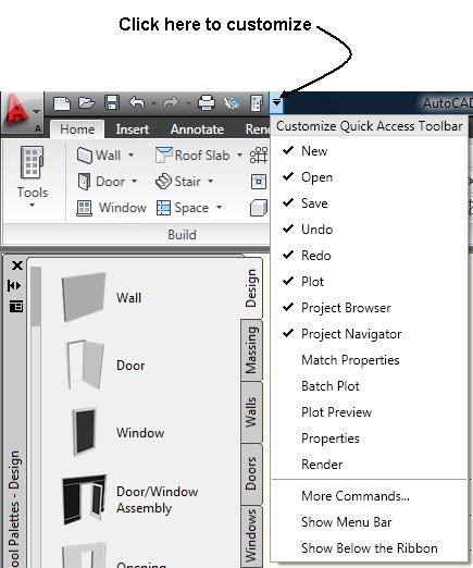
5 Quick Access Toolbar 5

6 AutoCAD Screen 6
7 AutoCAD Screen Layout 1. DRAWING AREA Location: The large area in the center of the screen. This is where you will draw. This area represents a piece of paper. The color of this area can be changed using Tools / Option / Display / Color. The default color is white 2. CROSSHAIRS / CURSOR Location: Can be anywhere in the Drawing Area. The movement of the cursor is controlled by the movement of the pointing device such as a mouse. You will use the cursor to locate points, make selections and draw objects. The size can be changed using Tools / Options / Display / Crosshair\Size. 3. COMMAND LINE Location: The three lines at the bottom of the screen. This is where you enter commands and Autocad will prompt you to input information. 4. COORDINATE DISPLAY (F6) Location: Lower left corner. In the Absolute mode (coords = 1): displays the location of the crosshairs / cursor in reference to the Origin. The first number represents the horizontal movement (Xaxis), the second number represents the vertical movement (Yaxis) and the third number is the Zaxis which is used for 3D. In the Relative Polar mode (coords = 2): displays the distance and angle of the cursor from the last point entered. (Distance<Angle) 7
8 AutoCAD Screen Layout 5. STATUS BAR Location: Below the Command Line. Displays your current settings. These settings can be turned on and off by clicking on the word (Snap, Grid, Ortho, etc.) or by pressing the function keys, F1, F2, etc. See button descriptions below. [SNAP] (F9): Increment Snap controls the movement of the cursor. If it is off, the cursor will move smoothly. If it is ON, the cursor will jump in an incremental movement. The increment spacing can be changed at any time using Tools / Drafting Settings / Snap and Grid. The default spacing is.250. [GRID] (F7): The grid (dots) is merely a visual "drawing aid". The default spacing is 1 unit. You may change the grid spacing at any time using: Tools / Drafting Settings /Snap and Grid. [ORTHO] (F8): When Ortho is ON, cursor movement is restricted to horizontal or vertical. When Ortho is OFF, the cursor moves freely. [POLAR] (F10): POLAR TRACKING creates Alignment Paths at specified angles. [OSNAP] (F3): RUNNING OBJECT SNAP. Specific Object Snaps can be set to stay active until you turn them off. [OTRACK] (F11): OBJECT SNAP TRACKING. Creates Alignment Paths at precise positions using object snap locations. [LWT] LINEWEIGHT: Displays the width assigned to each object. MODEL: Switches your drawing between paperspace and modelspace. 6. UCS ICON (User Coordinate System): Location: Lower left corner of the screen. The UCS icon indicates the location of the Origin. The UCS icon appearance can be changed using: View / Display / Icon /Properties. 7. ORIGIN: The location where the X, Y and Z axes intersect. 0,0,0 8


9 Snaps, etc. Snap to Grid cursor snaps to grid points Show Grid displays grid in model space Orthographic constrains lines to 90deg angles Polar Snap constrains lines to other angle increments Object Snap cursor snaps to points on objects Dynamic UCS shows UCS at all times Dynamic Input displays input text in space 9
10 AutoCAD Screen Layout FUNCTION KEYS F1 Help Explanations of Commands. F2 Flipscreen Toggles from Text Screen to Graphics Screen. F3 Osnap Toggles Osnap On and Off. F4 Tablet Toggles the Tablet On and Off. F5 Isoplane Changes the Isoplane from Top to Right to Left. F6 Coordinate Display Changes the display from ON / Off /. F7 Grid Toggles the Grid On or Off. F8 Ortho Toggles Ortho On or Off. F9 Snap Toggles Increment Snap on or off. F10 Polar Toggles Polar Tracking On or Off. F11 Otrack Toggles Object Snap Tracking On and Off. SPECIAL KEY FUNCTIONS Escape Key: Cancels the current command, menu or Dialog Box. Enter Key: Ends a command, or will repeat the previous command if the command line is blank. Space Bar : Same as the Enter Key, except when entering text 10
 Pull-down menu appears.")
 If you select a word with (5) Ellipsis..., a dialog box will appear.")
11 Pull-Down Menu Bar (1) The pull-down MENU BAR is located at the top of the screen. By selecting any of the words in the MENU BAR, a (2) Pull-down menu appears. If you select a word from the pull-down menu that has an (3) Arrow, a (4) Sub Menu will appear. (Example : Draw / Circle) If you select a word with (5) Ellipsis..., a dialog box will appear. (Example: Draw / Boundary ) DIALOG BOX Many commands have multiple options and require you to make selections. These commands will display a dialog box. Dialog boxes, such as the Hatch dialog box shown here, make selecting and setting options easy. 11
. These icon buttons can be selected to Draw or Edit objects and manage files.")
12 Toolbars AutoCAD provides several toolbars to access frequently used commands. (1)Standard, (2) Object Properties, (3) Draw, and (4) Modify toolbars are displayed by default. Toolbars contain icon buttons (5). These icon buttons can be selected to Draw or Edit objects and manage files. If you place the pointer on any icon and wait a second, a tool tip (6) will appear and a help message (7) will appear at the bottom of the screen. Toolbars can be floated or docked. Floating toolbars (8) move freely in the drawing area and can be resized. To move, place the pointer on the toolbar title then hold the left mouse button down, drag to the new location and release the mouse button. To resize, place the pointer on the right or bottom edge of the toolbar. When the pointer changes to a double ended arrow, hold the left mouse button down and drag. When desired size is achieved, release the mouse button. Docked toolbars (9) are locked into place along the top, bottom or sides of the AutoCad Window. To dock, place the pointer on the toolbar title, hold the left mouse button down and drag to the top, bottom, or either side of the AutoCAD window. When the outline of the toolbar appears, release the mouse button. 12
 PALETTES There are two types of Palettes within AutoCAD. The first type has been pre-designed by AutoCAD.")

13 Toolbars OPEN OR CLOSE TOOLBARS Many other toolbars are available by selecting View / Toolbars from the Pull-down menu. Select the Toolbars tab. A list of available toolbars will appear. (A check mark indicates the toolbars that are open.) PALETTES There are two types of Palettes within AutoCAD. The first type has been pre-designed by AutoCAD. An example of a pre-designed palette would be the Properties Palette shown This palette will appear automatically when you select the Properties command. The second type is a customizable Palette that you may create to hold frequently used commands, hatch patterns, symbols, etc. Palettes may be resized and moved to any location on the screen. They can be docked or float. The Auto-Hide function allows you to collapse the palette when the cursor is away From the palette. When you move the cursor over the Title Bar the Palette will reappear. 13
 Offset (O) Mirror (MI) Trim")
14 Command Interface Move (M) Scale (SC) Rotate (RO) Offset (O) Mirror (MI) Trim (TR) 14
 Polyline (PL) Rectangle")
15 Some 2D Common Commands Line (L) Circle (C) Polyline (PL) Rectangle (REC) 15
 6. Pick Specify next point or [Close/Undo]:(point) 7. Pick Specify next point or [Close/Undo]:(point) 8. Press ENTER to end line sequence, or 9.")
16 Drawing Lines (L) Creates single straight line segments 1. Choose Draw, Line, or 2. Click the Line icon, or 3. Type LINE from the command Prompt. Command: LINE or L 4. Press ENTER 5. Pick From point: (point) 6. Pick Specify next point or [Close/Undo]:(point) 7. Pick Specify next point or [Close/Undo]:(point) 8. Press ENTER to end line sequence, or 9. Type U to undo the last segment To point: U (undo), or 10. Type C to create a closed polygon To point : C (close) TIPS: You can continue the previous line or arc by responding to the From point: prompt with a space or ENTER. Choose the right mouse button for the line pop-up menu to appear while in the line command 16
17 Drawing Lines (L) Cartesian Coordinate System AutoCAD provides the user with an infinite two dimensional area to work with. Any entities place on the working two dimensional plane can be defined relative to the Cartesian coordinate system. The Cartesian coordinate system divides a two dimensional plane with two perpendicular axis. The X axis runs horizontal across the bottom of the screen. The Y axis runs vertically along the left side of the screen. These two axis intersect at the bottom left corner of the screen. Each of these axis is further divided into segments. Each segment is given a value. The X axis segments increase in value to the right. The positive X values are to the right of the intersection of the two axis. The negative X values are to the left. The positive Y values are above the intersection and increase up. The negative Y values are below. Absolute Coordinates Type x,y coordinate From point: 1,1 To point: 2,1 To point: 2,2 To point: 1,2 To point: 1,1 Relative Coordinates From point pick point To To To To Polar Coordinates From point: pick point To point:@1<0 To point:@1<90 To point:@1<180 To point:@1<270 17
18 Drawing Circles Circle Command 1. Choose Draw, Circle, or 2. Click the Circle icon, or 3. Type CIRCLE at the command prompt. Command: CIRCLE 4. Type One of the following options: 3P/2P/TTR/<<center point>>:, or 5. Pick A center point. 6. Type A radius or diameter, or 7. Pick A radius or diameter Diameter/<<radius>>: TIPS: To create circles that are the same size, press ENTER when asked for the circle radius. When selecting a circle with a pickbox, be sure to select the circumference of the circle. 18

19 Drawing Arc Arc Command 1. Choose Draw, Arc. or 2. Click the Arc icon., or 3. Type ARC at the command prompt Command: ARC 4. Draw One of the arcs. TIPS: Except for 3 point arcs, arcs are drawn in a COUNTERCLOCKWISE direction. While in the arc command, press the right mouse button to select the following options for arcs: 19


20 Units and Properties The units command will let you change the primary units you will be drawing in Properties will let you change just about anything with respect to the selected item 20
 Area")

21 Measure and Dimension The measure option has two important subcommands: Distance (DI) Area (AREA) The dimension tool has many options, and displays the measurement in the drawing 21

22 Viewports Viewports in layouts help you arrange your drawings into organized sheets at specific scales 22


23 Setting Up to Print You can apply a page setup to your layout to make the printing process quicker every time 23


24 3D You can change the user interface to 3D Basics or Modeling if you want to use buttons, or you can use keyboard entries EXT UNI SU You can rotate an object about the X or Y axis with the 3D rotate command (3R) 24
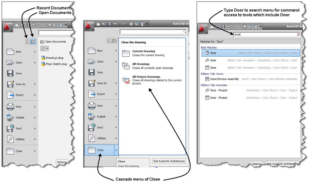
25 Application Menu 25


26 Setting Up the Workspace The options window lets you set all your preferences within the drawing. Snap and Aperture settings are on a totally personal basis 26


27 Right Click Customization Right-click settings are also personal preference Repeating commands and meaning enter make the drawing process faster 27


28 Preferences You can set the color of just about anything in the drawing The pick-box and grip sizes will help you manipulate your drawing 28
After completing this lesson, you will be able to:
 LEARNING OBJECTIVES After completing this lesson, you will be able to: 1. Create a template. 2. Understand the AutoCAD Window. 3. Understand the use of the function keys. 4. Select commands using the Pull-down
After completing this lesson, you will be able to:
 LEARNING OBJECTIVES After completing this lesson, you will be able to: 1. Create a template. 2. Understand the AutoCAD Window. 3. Understand the use of the function keys. 4. Select commands using the Pull-down
Getting Started. In This Chapter
 Getting Started In This Chapter 2 This chapter introduces concepts and procedures that help you get started with AutoCAD. You learn how to open, close, and manage your drawings. You also learn about the
Tutorial 3: Constructive Editing (2D-CAD)
") (2D-CAD) The editing done up to now is not much different from the normal drawing board techniques. This section deals with commands to copy items we have already drawn, to move them and to make multiple
(2D-CAD) The editing done up to now is not much different from the normal drawing board techniques. This section deals with commands to copy items we have already drawn, to move them and to make multiple
The Rectangular Problem
 C h a p t e r 2 The Rectangular Problem In this chapter, you will cover the following to World Class standards: The tools for simple 2D Computer Aided Drafting (CAD) The Command Line and the Tray The Line
Randy H. Shih. Jack Zecher PUBLICATIONS
 Randy H. Shih Jack Zecher PUBLICATIONS WWW.SDCACAD.COM AutoCAD LT 2000 MultiMedia Tutorial 1-1 Lesson 1 Geometric Construction Basics! " # 1-2 AutoCAD LT 2000 MultiMedia Tutorial Introduction Learning
Using Object Snap to Draw a Rug Design
 Using Object Snap to Draw a Rug Design The objective of the rest of this tutorial is to learn the use of object snap and hatch. Because AutoCAD is based on vectors and coordinate geometry, it can easily
CHAPTER 1 COPYRIGHTED MATERIAL. Getting to Know AutoCAD. Opening a new drawing. Getting familiar with the AutoCAD and AutoCAD LT Graphics windows
 CHAPTER 1 Getting to Know AutoCAD Opening a new drawing Getting familiar with the AutoCAD and AutoCAD LT Graphics windows Modifying the display Displaying and arranging toolbars COPYRIGHTED MATERIAL 2
StickFont Editor v1.01 User Manual. Copyright 2012 NCPlot Software LLC
 StickFont Editor v1.01 User Manual Copyright 2012 NCPlot Software LLC StickFont Editor Manual Table of Contents Welcome... 1 Registering StickFont Editor... 3 Getting Started... 5 Getting Started...
Tutorial Second Level
 AutoCAD 2018 Tutorial Second Level 3D Modeling Randy H. Shih SDC PUBLICATIONS Better Textbooks. Lower Prices. www.sdcpublications.com Powered by TCPDF (www.tcpdf.org) Visit the following websites to learn
Lesson 1 Parametric Modeling Fundamentals
 1-1 Lesson 1 Parametric Modeling Fundamentals Create Simple Parametric Models. Understand the Basic Parametric Modeling Process. Create and Profile Rough Sketches. Understand the "Shape before size" approach.
Controlling the Drawing Display
 Controlling the Drawing Display In This Chapter 8 AutoCAD provides many ways to display views of your drawing. As you edit your drawing, you can control the drawing display and move quickly to different
Exercise Guide. Published: August MecSoft Corpotation
 VisualCAD Exercise Guide Published: August 2018 MecSoft Corpotation Copyright 1998-2018 VisualCAD 2018 Exercise Guide by Mecsoft Corporation User Notes: Contents 2 Table of Contents About this Guide 4
Chapter 4. Part 1 AutoCAD Basics
 Chapter 4. Part 1 AutoCAD Basics Chapter Objectives Describe the AutoCAD screen layout. Perform an AutoCAD drawing setup, including setting units, limits, layers, linetypes, and lineweights. Explain the
7/21/2009. Chapters Learning Objectives. Fillet Tool
 Chapters 12-13 JULY 21, 2009 Learning Objectives Chapter 12 Chapter 13 Use the FILLET tool to draw fillets, rounds, and other rounded corners. Place chamfers and angled corners with the CHAMFER tool. Separate
Acknowledgement INTRODUCTION
 Submitted by: 1 Acknowledgement INTRODUCTION Computers are increasingly being used for doing engineering drawings and graphics work because computers allow the graphics designer or the draughtsman to change
Grips - Automatic Editing
 Grips - Automatic Editing Sacramento City College Engineering Design Technology Grips - Automatic Editing 1 Objectives Use grips to do automatic editing with the STRETCH, COPY, MOVE, ROTATE, SCALE and
Using Coordinate Systems
 Using Coordinate Systems In This Chapter 5 As you draw you use the coordinate system to specify points in the drawing. You can locate and use your own movable user coordinate system (UCS) for working on
1 Introduction to AutoCAD
 1 Introduction to AutoCAD The term CAD (Computer Aided Design) applies to a wide range of programs that allow th user to created drawings, plans, and designs electronically. AutoCAD is one such program
Object Snap. Sacramento City College Engineering Design Technology. Object Snap 1
 Object Snap Sacramento City College Engineering Design Technology Object Snap 1 Objectives Use OSNAP to create precision drawings Use object snap overrides for single point selections Set running object
SolidWorks Implementation Guides. User Interface
 SolidWorks Implementation Guides User Interface Since most 2D CAD and SolidWorks are applications in the Microsoft Windows environment, tool buttons, toolbars, and the general appearance of the windows
AutoCAD 2D Tutorial Chapter 25 Advanced Selection Commands
 Chapter 25 Advanced Selection Commands - 186 - Selection Modes 25.1 1. Choose Tools, Options... 2. Choose the Selection TAB from the following dialog. 3. Change the settings as desired. Noun/Verb Selection
Lesson 1 CAD Mechanical Part 1 Beginning Drawing Objectives
 Lesson 1 CAD Mechanical Part 1 Beginning Drawing Objectives In this assignment you will learn to identify important terminology and functions of AutoCAD, to begin a new drawing and save data in the proper
GEO 154 CARTOGRAPHY II- PLOTTING USING AUTOCAD- ASSIGMENT HELP
 GEO 154 CARTOGRAPHY II- PLOTTING USING AUTOCAD- ASSIGMENT HELP DOCUMENT. For one to two reasons data may not be in a format that can be integrated into AutoCAD software, but coordinates may be separated
NURBS modeling for Windows. Training Manual Level 1
 NURBS modeling for Windows Training Manual Level 1 Rhino Level 1 Training 2nd Ed.doc Robert McNeel & Associates 1997-2000 All Rights Reserved. Printed in U.S.A. Copyright by Robert McNeel & Associates.
Setting Up Your Drawing Environment
 Setting Up Your Drawing Environment In This Chapter 3 After you start a drawing, you can change its settings, including drawing units and limits, snap and grid settings, and layer, linetype, and lettering
AutoCADD Tutorial A survival guide
 AutoCADD Tutorial A survival guide Avery S.H. Copeland Prepared for IMDL Lab students and MIL volunteers October 9, 1997 Revised April 17, 1998 AutoCADD Tutorial Page 2 Contents Introduction Relative Coordinates
Control the Workplane
 Control the Workplane This tutorial outlines the procedures to understand and control the user coordinate system (UCS). You can realign and reorient the UCS to create and modify 3D objects on 2D workplanes
Rhinoceros NURBS modeling for Windows. Version 1.0 Training Manual Level 1
 Rhinoceros NURBS modeling for Windows Version 1.0 Training Manual Level 1 rhinolevel 1.doc Robert McNeel & Associates 1997. All Rights Reserved. Printed in U.S.A. Copyright by Robert McNeel & Associates.
Welcome to MicroStation
 Welcome to MicroStation Module Overview This module will help a new user become familiar with the tools and features found in the MicroStation design environment. Module Prerequisites Fundamental knowledge
GstarCAD Complete Features Guide
 GstarCAD 2017 Complete Features Guide Table of Contents Core Performance Improvement... 3 Block Data Sharing Process... 3 Hatch Boundary Search Improvement... 4 New and Enhanced Functionalities... 5 Table...
1 st Subject: AutoCAD 2000 Interface ABC: Methods of Command Entry, Open/Exit, Save Files
 Intermediate Engineering Graphics 4 th Week Lecture Notes Instructor: Edward N. Locke Topic: Review of AutoCAD 2000 Interface, Settings, Options, and Tools 1 st Subject: AutoCAD 2000 Interface ABC: Methods
Autodesk Fusion 360 Training: The Future of Making Things Attendee Guide
 Autodesk Fusion 360 Training: The Future of Making Things Attendee Guide Abstract After completing this workshop, you will have a basic understanding of editing 3D models using Autodesk Fusion 360 TM to
LABORATORY 4: TO CONSTRUCT CAD MULTIPLE VIEWS I AND II
 LABORATORY 4: TO CONSTRUCT CAD MULTIPLE VIEWS I AND II OBJECTIVES: After completing this session, you should be able to: 1. Use the User Coordinate System 2. Convert a solid model to a multiview using
To change the shape of a floating toolbar
 Modifying toolbars You can change the size of toolbar buttons and reposition, add, or delete toolbar buttons. You can also change the toolbar name and turn tooltips on and off. An important item to note-
solidthinking Environment...1 Modeling Views...5 Console...13 Selecting Objects...15 Working Modes...19 World Browser...25 Construction Tree...
 Copyright 1993-2009 solidthinking, Inc. All rights reserved. solidthinking and renderthinking are trademarks of solidthinking, Inc. All other trademarks or service marks are the property of their respective
AutoCAD 2009 User InterfaceChapter1:
 AutoCAD 2009 User InterfaceChapter1: Chapter 1 The AutoCAD 2009 interface has been enhanced to make AutoCAD even easier to use, while making as much screen space available as possible. In this chapter,
Spring 2011 Workshop ESSENTIALS OF 3D MODELING IN RHINOCEROS February 10 th 2011 S.R. Crown Hall Lower Core Computer Lab
 [1] Open Rhinoceros. PART 1 INTRODUCTION [4] Click and hold on the Boundary Lines in where they form a crossing and Drag from TOP RIGHT to BOTTOM LEFT to enable only the PERSPECTIVE VIEW. [2] When the
Parametric Modeling. With. Autodesk Inventor. Randy H. Shih. Oregon Institute of Technology SDC PUBLICATIONS
 Parametric Modeling With Autodesk Inventor R10 Randy H. Shih Oregon Institute of Technology SDC PUBLICATIONS Schroff Development Corporation www.schroff.com www.schroff-europe.com 2-1 Chapter 2 Parametric
Chapter 1: Introduction
 Modeling in 3-D is the process of creating a mathematical representation of an object's surfaces. The resulting model is displayed on your screen as a two-dimensional image. Rhino provides tools for creating,
S206E Lecture 3, 5/15/2017, Rhino 2D drawing an overview
 Copyright 2017, Chiu-Shui Chan. All Rights Reserved. S206E057 Spring 2017 Rhino 2D drawing is very much the same as it is developed in AutoCAD. There are a lot of similarities in interface and in executing
Ansoft HFSS Windows Screen Windows. Topics: Side Window. Go Back. Contents. Index
 Modifying Coordinates Entering Data in the Side Windows Modifying Snap To Absolute Relative Each screen in divided up into many windows. These windows can allow you to change the coordinates of the model,
Press the Plus + key to zoom in. Press the Minus - key to zoom out. Scroll the mouse wheel away from you to zoom in; towards you to zoom out.
 Navigate Around the Map Interactive maps provide many choices for displaying information, searching for more details, and moving around the map. Most navigation uses the mouse, but at times you may also
In this chapter, I explain the essentials that you need to start drawings. After a
 In this chapter, I explain the essentials that you need to start drawings. After a little background, I discuss the basics of the screen that you see when you open AutoCAD or AutoCAD LT, and how to use
Module 1: Basics of Solids Modeling with SolidWorks
 Module 1: Basics of Solids Modeling with SolidWorks Introduction SolidWorks is the state of the art in computer-aided design (CAD). SolidWorks represents an object in a virtual environment just as it exists
3 AXIS STANDARD CAD. BobCAD-CAM Version 28 Training Workbook 3 Axis Standard CAD
 3 AXIS STANDARD CAD This tutorial explains how to create the CAD model for the Mill 3 Axis Standard demonstration file. The design process includes using the Shape Library and other wireframe functions
Excerpt from "Inside CorelCAD" - Windows edition To purchase the full book, please go to
 chapter 3 CAD Concepts 37 1. Start any drawing command, such as Line. : line Specify start point» (Move cursor.) 2. Right-click the coordinate field. Notice the short cut menu. 3. Choose Relative. (The
Chapter 1. Getting Started with AutoCAD
 Chapter 1 Getting Started with AutoCAD 3 4 AutoCAD 2002: The Complete Reference This chapter takes you on a tour of AutoCAD and provides an overview of the different components of the AutoCAD screen. It
AutoCAD 2009 Configuration for MUS
 AutoCAD 2009 Configuration for MUS NOTE: The following steps do not apply to AutoCAD 2006 or earlier versions. These steps must be done before attempting to use MicroScribe Utility Software (MUS) with
SolidWorks Intro Part 1b
 SolidWorks Intro Part 1b Dave Touretzky and Susan Finger 1. Create a new part We ll create a CAD model of the 2 ½ D key fob below to make on the laser cutter. Select File New Templates IPSpart If the SolidWorks
Autodesk Inventor Design Exercise 2: F1 Team Challenge Car Developed by Tim Varner Synergis Technologies
 Autodesk Inventor Design Exercise 2: F1 Team Challenge Car Developed by Tim Varner Synergis Technologies Tim Varner - 2004 The Inventor User Interface Command Panel Lists the commands that are currently
User Manual Version 1.1 January 2015
 User Manual Version 1.1 January 2015 - 2 / 112 - V1.1 Variegator... 7 Variegator Features... 7 1. Variable elements... 7 2. Static elements... 7 3. Element Manipulation... 7 4. Document Formats... 7 5.
MET 107 Drawing Tool (Shapes) Notes Day 3
 Notes Day 3") MET 107 Drawing Tool (Shapes) Notes Day 3 Shapes: (Insert Tab Shapes) Example: Select on the rounded rectangle Then use the mouse to position the upper left corner and produce the size by dragging out
MET 107 Drawing Tool (Shapes) Notes Day 3 Shapes: (Insert Tab Shapes) Example: Select on the rounded rectangle Then use the mouse to position the upper left corner and produce the size by dragging out
Modeling a Gear Standard Tools, Surface Tools Solid Tool View, Trackball, Show-Hide Snaps Window 1-1
 Modeling a Gear This tutorial describes how to create a toothed gear. It combines using wireframe, solid, and surface modeling together to create a part. The model was created in standard units. To begin,
SolidWorks 2½D Parts
 SolidWorks 2½D Parts IDeATe Laser Micro Part 1b Dave Touretzky and Susan Finger 1. Create a new part In this lab, you ll create a CAD model of the 2 ½ D key fob below to make on the laser cutter. Select
EXPERIMENT NO: NAME OF EXPERIMENT: -01 2D & 3D CAD modelling methodology using package AutoCAD.
 SHRI SHIVAJI EDUCATION SOCIETY, AMRAVATI S, COLLEGE OF ENGINEERING & TECHNOLOGY, AKOLA Babhulgaon (JH) N.H.No.6, Akola-444104 DEPARTMENT OF MECHANICAL ENGINEERING COMPUTER SOFTWARE APPLICATIONS -I LAB.
Kate Morrical s Tips and Tricks for Using AutoCAD LT 2011
 Kate Morrical s s and Tricks for Using AutoCAD LT 2011 This table of contents is interactive! Clicking on the section title or page number will bring you right to that section. The User Interface 2 The
COMPUTER AIDED DESIGN CURRICULLOM RHINO BASED 3D DESIGN
 COMPUTER AIDED DESIGN CURRICULLOM RHINO BASED 3D DESIGN S.no. CONTENTS Page no S. no. CONTENTS PAGE no. 1. Introduction 1 2. Necessary of Rhino in Designing 2 3. Working with 3D Models 3 4. Object Types
Table of content CONTENT OF THE TRAINING PACKAGE... 1 MODULE 1: UNDERSTANDING A DWG-DRAWING... 2
 V14 Basic Training Table of content CONTENT OF THE TRAINING PACKAGE... 1 1 Documentation... 1 2 Exercises... 1 3 Software... Fout! Bladwijzer niet gedefinieerd. MODULE 1: UNDERSTANDING A DWG-DRAWING...
Getting Familiar with AutoCAD
 4397c01.fm Page 1 Monday, March 14, 2005 2:04 PM Chapter 1 Getting Familiar with AutoCAD If you are totally new to AutoCAD, you ll want to read this chapter. It provides an overview of AutoCAD s layout
QuickTutor. An Introductory SilverScreen Modeling Tutorial. Solid Modeler
 QuickTutor An Introductory SilverScreen Modeling Tutorial Solid Modeler TM Copyright Copyright 2005 by Schroff Development Corporation, Shawnee-Mission, Kansas, United States of America. All rights reserved.
Introduction to AutoCAD 2010
 Page 1 Introduction to AutoCAD 2010 Alf Yarwood Chapter 2 Exercise 1 1. Open AutoCAD 2010 - either with a double-click on its start-up icon in the Windows desktop, or by using the method on the computer
INTRODUCTION... 1 DOCUMENT CONVENTIONS... 1
 INTRODUCTION... 1 DOCUMENT CONVENTIONS... 1 BEGINNING AUTOCAD... 2 USING THE START BUTTON TO LAUNCH AUTOCAD... 2 USING A SHORTCUT TO LAUNCH AUTOCAD... 2 AUTOCAD USER INTERFACE... 3 CHOOSING COMMANDS...
Customizing Interface Elements and Commands Part 02
 Customizing Interface Elements and Commands Part 02 Sacramento City College Engineering Design Technology Customizing Interface Elements and Commands 1 Creating New Commands Customizing Interface Elements
Parametric Modeling with. Autodesk Fusion 360. First Edition. Randy H. Shih SDC. Better Textbooks. Lower Prices.
 Parametric Modeling with Autodesk Fusion 360 First Edition Randy H. Shih SDC PUBLICATIONS Better Textbooks. Lower Prices. www.sdcpublications.com Powered by TCPDF (www.tcpdf.org) Visit the following websites
User Interface Guide
 User Interface Guide 1 Contents Overview... 3 Tabmenu... 4 Design modes... 4 Tool groups... 5 Design function groups... 5 Main menu... 6 Toolbars... 7 Drawing area... 9 Status bar... 11 Coordinate box...
Piping Design. Site Map Preface Getting Started Basic Tasks Advanced Tasks Customizing Workbench Description Index
 Piping Design Site Map Preface Getting Started Basic Tasks Advanced Tasks Customizing Workbench Description Index Dassault Systèmes 1994-2001. All rights reserved. Site Map Piping Design member member
7/7/2009. Chapter 7 Object Snaps and Autotracking. Chapter 7 Learning Objectives. Object Snap. Object Snap. Object Snap
 Chapter 7 Learning Objectives Chapter 7 Object Snaps and Autotracking JULY 7, 2009 Set running object snap modes for continuous use. Use object snap overrides for single point selections. Select appropriate
Working with Plan Production ObjectsChapter1:
 Chapter 1 Working with Plan Production ObjectsChapter1: The lessons in this chapter guide you through the processes of creating and working with plan production objects. Plan production objects include
FILE MENU New Starts a New Blank Canvas Open- Allows you to import designs into the program. Close- Closes the current Design
 1 Quick Start Guide This guide is intended to give you an overview of the function of the program. The guide is arranged by section, Each section corresponds to the different pulldown menus in the program.
Blocks reduce drawing size since multiple instances of a block are stored in one definition.
 AGENDA: 1. Blocks and Controlling Block Properties 2. Creating and Inserting Blocks 3. Editing Blocks after Insertion 4. Storing Blocks Blocks A block is a collection of entities, grouped together and
Introduction to AutoCAD 2010
 Introduction to AutoCAD 2010 Alf Yarwood Chapter 3 Exercise 1 1. Open AutoCAD 2010 with a double-click on its shortcut icon in the Windows desktop. 2. Call the Line tool with a left-click on its tool icon
Chapter 12: Pull Toy - Solids and Transforms
 This tutorial demonstrates using solid primitives and simple transforms. You will learn how to: Enter coordinates to place points exactly. Draw a free-form curve and polygon. Create a pipe along a curve.
Visual 2012 Help Index
 Visual 2012 Help Index Absolute Coordinates 2.1 Cartesian Coordinates Aim 7.4.3 Place and Aim Luminaires 7.4.4 Reaiming Luminaires Align Cursor and Plane to Current View 9.6 Align to View Align Cursor
ezimagex2 User s Guide Version 1.0
 ezimagex2 User s Guide Version 1.0 Copyright and Trademark Information The products described in this document are copyrighted works of AVEN, Inc. 2015 AVEN, Inc. 4595 Platt Rd Ann Arbor, MI 48108 All
Lesson 5 Solid Modeling - Constructive Solid Geometry
 AutoCAD 2000i Tutorial 5-1 Lesson 5 Solid Modeling - Constructive Solid Geometry Understand the Constructive Solid Geometry Concept. Create a Binary Tree. Understand the basic Boolean Operations. Create
Rhinoceros NURBS modeling for Windows. Training Manual Level 1
 Rhinoceros NURBS modeling for Windows Training Manual Level 1 R30TML1-08-2005 Rhinoceros Level 1 Training Manual v3.0 Robert McNeel & Associates 2005 All Rights Reserved. Printed in U.S.A. Copyright by
Introduction to Microsoft Word 2008
 1. Launch Microsoft Word icon in Applications > Microsoft Office 2008 (or on the Dock). 2. When the Project Gallery opens, view some of the available Word templates by clicking to expand the Groups, and
Basic Modeling 1 Tekla Structures 12.0 Basic Training September 19, 2006
 Tekla Structures 12.0 Basic Training September 19, 2006 Copyright 2006 Tekla Corporation Contents Contents 3 1 5 1.1 Start Tekla Structures 6 1.2 Create a New Model BasicModel1 7 1.3 Create Grids 10 1.4
CBCL Limited Tool Palettes Tutorial 2012 REV. 01. CBCL Design Management & Best CAD Practices. Our Vision
 CBCL Limited Tool Palettes Tutorial CBCL Design Management & Best CAD Practices 2012 REV. 01 Our Vision To be the most respected and successful Atlantic Canada based employeeowned firm, delivering multidiscipline
Introduction to SolidWorks Basics Materials Tech. Wood
 Introduction to SolidWorks Basics Materials Tech. Wood Table of Contents Table of Contents... 1 Book End... 2 Introduction... 2 Learning Intentions... 2 Modelling the Base... 3 Modelling the Front... 10
Schematic Editing Essentials
 Summary Application Note AP0109 (v2.0) March 24, 2005 This application note looks at the placement and editing of schematic objects in Altium Designer. This application note provides a general overview
Chapter 2 Parametric Modeling Fundamentals
 2-1 Chapter 2 Parametric Modeling Fundamentals Create Simple Extruded Solid Models Understand the Basic Parametric Modeling Procedure Create 2-D Sketches Understand the Shape before Size Approach Use the
Let s Make a Front Panel using FrontCAD
 Let s Make a Front Panel using FrontCAD By Jim Patchell FrontCad is meant to be a simple, easy to use CAD program for creating front panel designs and artwork. It is a free, open source program, with the
Never Digitize Again! Converting Paper Drawings to Vector
 December 2-5, 2003 MGM Grand Hotel Las Vegas Never Digitize Again! Converting Paper Drawings to Vector Felicia Provencal GD42-3L How many hours have you spent hunched over a digitizing board converting
Introduction to AutoCAD 2008
 Introduction to AutoCAD 2008 This page intentionally left blank Introduction to AutoCAD 2008 2D and 3D Design Alf Yarwood AMSTERDAM BOSTON HEIDELBERG LONDON NEW YORK OXFORD PARIS SAN DIEGO SAN FRANCISCO
L E S S O N 2 Background
 Flight, Naperville Central High School, Naperville, Ill. No hard hat needed in the InDesign work area Once you learn the concepts of good page design, and you learn how to use InDesign, you are limited
Instructor: Dr.Ashok Kaushal
 Continuing Education Department AutoCAD Instructor: Dr.Ashok Kaushal E-mail: ashok_kaushal@hotmail.com Topics Intro to CAD, Geometric commands, Absolute & Relative values, Line, Circle, Arc Dr. Ashok Kaushal
Module: Computer Aid Design
 Module: Computer Aid Design Lesson 1: Introduction to AutoCAD 2010 & Drafting Commands 1. AUTOCAD OVERVIEW CAD= Computer Aided Design, (1982) 1.1 User Interface: 1.2 Info Center Page 1 of 14 1.3 Zoom 1.3
Note: To open the new drawing, check the Open new drawing check box.
 Table of Contents Space Allocation Drawings.................................. 3 Set Up Space Allocation Groups.............................. 3 Checking In/Out and Pinning Space Allocations..................
by Paul Richard and Jim Fitzgerald
 Chapter 5 - Drawing Tools and Drafting Settings by Paul Richard and Jim Fitzgerald Richard / Fitzgerald :INTRODUCTION TO AutoCAD 2012 Copyright 2012 Pearson Education, Upper Saddle River, NJ 07458. All
Speedway. Body. (S) on the Sketch toolbar. Fig. 1
 on the Sketch toolbar. Fig. 1") Chapter 1 A. New Part. Step 1. Click File Menu > New. Speedway Body Step 2. Click Part from the list and click OK, Fig. 1. B. Sketch Construction Rectangle. Step 1. Click Right Plane in the Feature Manager
Chapter 1 A. New Part. Step 1. Click File Menu > New. Speedway Body Step 2. Click Part from the list and click OK, Fig. 1. B. Sketch Construction Rectangle. Step 1. Click Right Plane in the Feature Manager
Back to Flat Producing 2D Output from 3D Models
 Back to Flat Producing 2D Output from 3D Models David Cohn Modeling in 3D is fine, but eventually, you need to produce 2D drawings. In this class, you ll learn about tools in AutoCAD that let you quickly
I. Getting started in ARCHLine.XP
 I. Getting started in 1 Introduction 3 1. Introduction 1.1. Definition ARCHLine.XP is a Building Information Modeller, which supports the creation of planning- and implementation documentation, tender
Appendix B Import (CAD Transfer) Mode Keyboard Shortcuts
 Mode Keyboard Shortcuts") Import (CAD Transfer) Mode Keyboard Shortcuts Mode-Changing Keys E F H W V P Switch to Edit mode (press twice for Entry mode) Switch to Profile View mode Switch to Highway mode (if available) Switch to
Import (CAD Transfer) Mode Keyboard Shortcuts Mode-Changing Keys E F H W V P Switch to Edit mode (press twice for Entry mode) Switch to Profile View mode Switch to Highway mode (if available) Switch to
XPEL DAP SUPPORT. DAP Tool List & Overview DESCRIPTION ICON/TOOL (SHORTCUT)
") Pointer (S) Left-click on individual entities to add them to the current selection (selected entities will turn red). If the entity selected is a member of a group, the entire group will be added to the
Pointer (S) Left-click on individual entities to add them to the current selection (selected entities will turn red). If the entity selected is a member of a group, the entire group will be added to the
Introduction Make a plan with tool Rectangle Measurements Toolbar Enter Return Measurements Toolbar Measure Protractor
 Introduction Open SketchUp, and an empty file appears. You are looking at the red-green plane, and the blue axis (vertical) is pointing toward you. By default, you are in the Line tool, as indicated by
4. If you are prompted to enable hardware acceleration to improve performance, click
 Exercise 1a: Creating new points ArcGIS 10 Complexity: Beginner Data Requirement: ArcGIS Tutorial Data Setup About creating new points In this exercise, you will use an aerial photograph to create a new
Google LayOut 2 Help. Contents
 Contents Contents... 1 Welcome to LayOut... 9 What's New in this Release?... 10 Learning LayOut... 12 Technical Support... 14 Welcome to the LayOut Getting Started Guide... 15 Introduction to the LayOut
Autodesk Inventor - Basics Tutorial Exercise 1
 Autodesk Inventor - Basics Tutorial Exercise 1 Launch Inventor Professional 2015 1. Start a New part. Depending on how Inventor was installed, using this icon may get you an Inch or Metric file. To be