Motor protection circuit breakers
|
|
|
- Gregory Lane
- 5 years ago
- Views:
Transcription


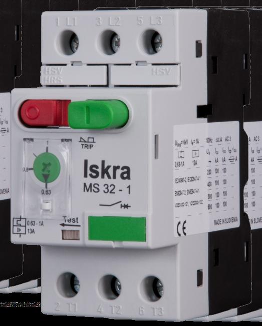
1 R Motor protection circuit breakers Motor protection circuit breakers are used for start-up and protection of electric motors (industry, small machines, external use, agricultural machines, compressors, repair shops, etc.).


2 Motor protection circuit breakers are a special type of circuit breakers designed for protection of wide range of single-phase and three-phase C motors against overload and short circuit. For motor protection: ll kind of C induction motors For three-phase motors up to kw Protection of other loads: Various low-inductive loads Version for single-phase consumers Version for transformer protection Version for short-circuit protection Other benefits: Wide range accessories Mounting on 5 rail Horizontal or vertical operating position Motor protection circuit breakers MS up to... page Motor protection circuit-breakers MS8 up to 8... page ccessories for MS, MS8... page 4 Motor protection circuit breakers MS up to... page 7 ccesories for MS... page 9 ccessories - general... page Ordering data... page, 8 Technical characteristics... page Dimensions... page 4
 0.... 0.6 0.6... 0. 0.... 0.4 0.")

3 MS, MS8 Motor protection circuit-breakers areas of use MS8 MS MS-TR Motor protection Overload protection Short-circuit protection Single-phase consumers Transformer protection Motor protection circuit breakers MS with overload and short-circuit release C- acc. to IECEN MS-0.6 MS-0. MS-0.4 MS-0.6 MS- MS-.6 MS-.5 MS-4 MS-6. MS-0 MS-4 MS-8 MS- MS-7 MS- Setting range () Motor power (-phase, 400 V) (kw) Circuit breakers for transformer protection MSTR with overload and short-circuit release C- acc. to IECEN MSTR-.5 MSTR-4 MSTR-6. MSTR-0 MSTR-4 MSTR-8 MSTR- MSTR-7 MSTR- Setting range ()
 0.... 0.6 0.6... 0. 0.... 0.4 0.4... 0.6 0.6.......6.6....5.5... 4 4... 6. 6.... 0 9... 4... 8 Motor power (-phase, 400 V) (kw) 0.06 0.09 0.... 0.8 0.8... 0. 0.7... 0.55 0.")
4 MS, MS8 Motor protection circuit breakers MS8 with overload and short-circuit release C- acc. to IECEN MS8-0.6 MS8-0. MS8-0.4 MS8-0.6 MS8- MS8-.6 MS8-.5 MS8-4 MS8-6. MS8-0 MS8-4 MS8-8 Setting range () Motor power (-phase, 400 V) (kw) Ordering data MS 4 Setting range () Example: The same switch with under-voltage release for control voltage V with an auxiliary switch with two NO contacts, built in the enclosure, with an emergency stop push-button and green signal lamp for 0 V: MS - 4 UR HS 0 HO4 NT SSz 0


5 ccessories - MS, MS8 uxiliary contact block HSV C-5, DC- acc. to IECEN HSV0 HSV0 Number of contacts NO NC 0 0 Wiring diagram HSV contact changes position from its normal state when the MSMS8 MPCB is switched on. Trip-indicating contact block HRS C-5, DC- acc. to IECEN HRS0 HRS0 Number of contacts NO NC 0 0 Wiring diagram HRS contact changes position from its normal state when the MSMS8 MPCB trips due to overload, short-circuit or manual depression of the TEST lever. uxiliary contact block for lateral mounting HS C-5, DC- acc. to IECEN HS0 HS HS0 Number of contacts NO NC 0 0 Wiring diagram dapters for connection of MSMS8 with a contactor Used for MSK07 MSKNL9 MSKNL K07 KNL9... KNL8 KNL... KNL
 8.90.54 8.90.55 8.90.94 8.90.56 8.90.46 8.")
* 4 4 0 0 0 0 40 40 400 400 45 45 4 4")


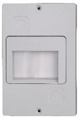
6 ccessories - MS, MS8 Under-voltage release UR Voltage (V)* Frequency (Hz) Shunt release R Voltage (V)* Frequency (Hz) * UR and R releases for other control voltagefrequencies are on request. Enclosures for MSMS8 Enclosure HO-4 Enclosure HO-55 Frame FP-4 Frame FP-55 Front plate P-4 Front plate P-55 Degree of protection IP4 IP55 IP4 IP55 IP4 IP P-455 FP-455 HO-455 5


 V 400 V.000..009.")
 V 400 V.009.6.")
7 ccessories - MS, MS8 ccessories for enclosures HO-455, FP-455, P-455 Voltage Emergency stop push-button E Emergency stop push-button with keylock E-K Padlocking feature HZ Push-button diaphragm IP Neutral link NL Signal lamp SSr (Red) V 400 V Signal lamp SSz (Green) V 400 V Signal lamp SSb (Transparent) V 400 V Cable inlet M x
 0.... 0.6 0.6... 0. 0.... 0.4 0.")

8 MS Motor protection circuit-breakers areas of use MS MST MS0 MS-TR MSZ MPE Motor protection Overload protection Short-circuit protection Single-phase consumers Transformer protection Motor protection circuit breakers MS with overload and short-circuit release C- acc. to IECEN MS-0.6 MS-0. MS-0.4 MS-0.6 MS- MS-.6 MS-.5 MS-4 MS-6. MS-0 MS-6 MS-0 MS- Setting range () Motor power (-phase, 400 V) (kw) Motor protection circuit breakers MST with overload release C- acc. to IECEN MST-0.4 MST-0.6 MST- MST-.6 MST-.5 MST-4 MST-6. MST-0 MST-6 MST-0 MST- Setting range () Motor power (-phase, 400 V) (kw)
 0.... 0.6 0.6... 0. 0.... 0.4 0.4... 0.6 0.6.......6.6....5.5... 4 4... 6. 6.... 0 0... 6 6... 0 Motor power (single-phase, 0-40 V) (kw) 0.06... 0.09 0. 0.8... 0. 0.7 0.")
 0. Motor power (-phase, 400 V) (kw) 0.06 0.07.879 Circuit breakers for short-circuit protection MSZ with short-circuit release MSZ-0.6 MSZ-0.")
9 MS Motor protection circuit breakers MS0 with overload and short-circuit release C- acc. to IECEN MS0-0.6 MS0-0. MS0-0.4 MS0-0.6 MS0- MS0-.6 MS0-.5 MS0-4 MS0-6. MS0-0 MS0-6 MS0-0 Setting range () Motor power (single-phase, 0-40 V) (kw) Circuit breakers for single-phase consumers MPE with overload and short-circuit release C- acc. to IECEN MPE Setting range () 0. Motor power (-phase, 400 V) (kw) Circuit breakers for short-circuit protection MSZ with short-circuit release MSZ-0.6 MSZ-0. Setting range () Motor power (-phase, 400 V) (kw) Circuit breakers for transformer protection MSTR with overload and short-circuit release C-6a acc. to IECEN MSTR-.5 MSTR-4 MSTR-6. MSTR-0 MSTR-6 MSTR-0 MSTR- Setting range () Ordering data MS 4 Setting range () Example: The same switch with under-voltage release for control voltage V with an auxiliary switch with two NO contacts, built in the enclosure, with an emergency stop push-button and green signal lamp for 0 V: MS - 4 U PS 0 O4 NT SSz 0 8
* 4 4 48 48 0 0 0 0 0 0 400 400 45 45 4 4 0 0 0 0 Frequency (Hz) 8.")
* 4 4 48 48 0 0 0 0 0 0 400 400 45 45 4 4 0 0 0 0 Frequency (Hz) 8.90. 8.90.95 8.")

10 ccessories - MS uxiliary contact block for lateral mounting PS PS0 Number of contacts NO NC 0 Wiring diagram PS PS PS Under-voltage release U Voltage (V)* Frequency (Hz) Shunt release Voltage (V)* Frequency (Hz) * U and releases for other control voltagefrequencies are on request. 9


 Conductor")

11 ccessories - MS Trip-indicating auxiliary contact block RS RS0 RS0 Number of contacts NO NC 0 0 Wiring diagram RS contact changes position from its normal state when the MS MPCB trips due to overload, short-circuit or the manual depression of the TEST lever. dapters for connection of MS with a contactor Conductor lenght () Conductor cross-section ( ) Thermal current () DST-U DST-U DST-U-.5 L Enclosures for MS Enclosure O-4 Enclosure O-55 Front plate CP-4 Front plate CP-55 Degree of protection IP4 IP55 IP4 IP CP-455 O-455 0


 V 400 V.009.")
12 ccessories - MS ccessories for enclosures O-455 and CP-455 Voltage Emergency stop push-button NT Emergency stop push-button with keylock NT-K Padlocking feature Z Push-button diaphragm IP Neutral link NL Signal lamp SSr (Red) V 400 V Signal lamp SSz (Green) V 400 V Signal lamp SSb (Transparent) V 400 V Cable inlet M x
 70 90 45 00 655.00.00 655.00.00 655.00.00 655.00.004 655.00.005 655.00.006 655.00.007 655.")
 L L L L L L L L L 45 9... Supply block ( ) ESB-SV-MS 655.00.")
13 ccessories Connection blocks MSS-L MSS-L-M-45 MSS-L-M-45 MSS-L-M4-45 MSS-L-M5-45 MSS-L-M + Hi MSS-L-M + Hi MSS-L-M4 + Hi MSS-L-M5 + Hi Number of MPCB Lenght () MSS-L-Mx-45 connection blocks L L L L L L L L L MSS-L-Mx connection blocks (for MPCB with side-mounted accessories) L L L L L L L L L Supply block ( ) ESB-SV-MS Protection for connection cable BS-MS

14 i Technical characteristics Dimensions
15 MS, MS8 GENERL MIN CIRCUIT SFETY 4 TECHNICL DT Use Standards pprovals Climatic class Degree of protection Mounting Mounting position mbient temperature Storage temperature Temperature range of thermal compensation Maximum altitude (MSL) * m 000 Mechanical endurance Electrical endurance Trip class acc. to IEC Utilization category acc. to IEC Utilization category acc. to IEC 947- Max. switching frequency Shock resistance acc. to IEC Vibration resistance acc. to IEC Overvoltage category Pollution degree op. c. op. c. op. c.h g g Rated insulation voltage U i V Rated impulse withstand voltage U imp kv g Terminal capacity: rigid flexible flexible with end sleeve Conductor insulation stripping lenght Screw Screw type Tightening torque Nominal current Current setting Nominal current range Nominal frequency Max. operational voltage Themal current Max. motor current C- Number of all poles Number of protected poles Contact gap (per pole) Release type Operating current of thermal overload release Operating current of magnetic release (fixed) Sensitivity to phase failure Power dissipation at I n (all poles) MTTF - Mean time to failure MTTF = λ = B0(0. n op) MTTF d - Mean time to failure dangerous MTTF d = λ d = B0 d(0. n op) B0 - Number of operating cycles until 0 % of devices fail B0 d - Number of operating cycles until 0 % of device dangerous B0 d = B0ratio of dangerous failures λ - Failure rate λ = (0, n op)b0 λ - Failure rate dangerous λ d = (0, n op)b0d Ratio of dangerous failures n op - Operating cycles (operating cyclesh) Symbol Unit MS MS8 S I n f U e I th C C C W % op.h * NOTE: bove 000 m voltages U i and U e are reduced by % for every 00 m and current I e by % for every 0 m. I n I T Nm Hz V h h op. op. h h motor protection IECEN 947-, IECEN , IECEN 947-, IECEN , IECEN 04, UL 947 IECEN 04, UL 947 CS. No. 4 CS. No. 4 CE, UL, EC CE Constant damp heat acc. to IEC Cyclic damp heat acc. to IEC IP0, after terminals covering IP40 5 DIN rail (EN 75) any (C-), (DC-5) 0 C- 0 5 (at f= 5... Hz) III M PZ, with self-lifting clamp protected from falling out.0 0.6, 0., 0.4, 0.6,,.6,.5, 6., 0, 4, 8,, 7, 0.6, 0., 0.4, 0.6,,.6,.5, 6., 0, 4, , , , , 0.6-, -.6,.6-.5,.4-4, , , , , 0.6-, -.6,.6-.5,.4-4, , 9-4, -8, 7-, 0-7, , 9-4, thermal-magnetic.05 I r < I <. Ir I n ± 0 % yes x 0-4 x 0 0
16 MS, MS8 Switch selection for motor protection Single-phase 0 V 0 V 40 V V 0 V 40 V Standard motor powers Three-phase Setting range V 6 V 400 V 440 V 5 V 690 V 45 V kw MS motor protection switches, rated ultimate and service short-circuit breaking capacity I and I and max. back-up fuses if short circuit current I exceeds I cu cs cp cu MS MS - 0. MS MS MS - MS -.6 MS -.5 MS - 4 MS - 6. MS - 0 MS - 4 MS - 8 MS - MS - 7 MS - MS8-0.6 MS8-0. MS8-0.4 MS8-0.6 MS8 - MS8 -.6 MS8 -.5 MS8-4 MS8-6. MS8-0 MS8-4 MS8-8 Operating current of short-circuit release () Rated ultimate short-circuit breaking capacity I cu, Ics (k) 0 V 400 V 0 V 690 V 0 V 400 V 0 V 690 V I cu I cs I cu I cs I cu I cs I cu I cs Max. back-up fuse, if I cp > Icu (gl) (k) No back-up fuse required
17 MS, MS8 Tripping characteristics Tripping time t (s) 0 0, 0,0 0, Operational Current x e I () 6


18 MS, MS8 - ccessories Mounting positions of accessories HRS HSV HS UR, R MS PP 7
19 MS, MS8 - ccessories uxiliary switch for side mounting HS TECHNICL DT Standards pprovals Rated impulse voltage Rated insulation voltage Thermal current Rated operational current C-5 (40 V) Rated operational current DC- ( V) Contact rating code designation for CDC Mechanical endurance Electrical endurance Terminal capacity Conductor insulation stripping length Screw type Screw head Tightening torque U imp U i I th I e I e S V V op. c. op. c. Nm IEC , UL CE, UL, EC 6 kv B00 R M.5 PZ uxiliary contact block HSV, Trip indicating contact block HRS TECHNICL DT Standards pprovals Rated impulse voltage Rated insulation voltage Thermal current Rated operational current C-5 (40 V) Rated operational current DC- ( V) Contact rating code designation for CDC Mechanical endurance Electrical endurance Terminal capacity Conductor insulation stripping length Screw type Screw head Tightening torque U imp U i I th I e I e S V V op. c. op. c. Nm IEC , UL CE, UL, EC B00 R M.5 PZ 0.6 Under-voltage release UR, Shunt release R TECHNICL DT UR R Standards pprovals Control voltages (C) Rated frequency Pick-up voltage Drop-out voltage Power consumption switch-on operation switch-on operation Duty cycle Noise level Mechanical and electrical endurance Terminal capacity Conductor insulation stripping length Screw type Screw head Tightening torque U c U c f t ONtOFF V V Hz x U c % db op. Nm IECEN 947-, UL 947- CE, UL, EC 4, 0, 0, 40, 400, 45, 4, 0, 0 < 0.85 < VW < 5 min M.5 PZ 8
20 MS TECHNICL DT GENERL MIN CIRCUIT Use Standards pprovals Climatic class Degree of protection Mounting Mounting position mbient temperature Storage temperature Temperature range of thermal compensation Maximum altitude (MSL) * Mechanical endurance Electrical endurance Trip class acc. to IEC Utilization category acc. to IEC Utilization category acc. to IEC 947- Max. switching frequency Shock resistance acc. to IEC Vibration resistance acc. to IEC Overvoltage category Pollution degree Rated insulation voltage Rated impulse withstand voltage Terminal capacity: rigid flexible flexible with end sleeve Conductor insulation stripping lenght Screw Screw type Tightening torque Nominal current Current setting Nominal current range Nominal frequency Max. operational voltage Themal current Max. motor current C- Max. motor current DC-5 (max. V DC, all poles in series) Number of all poles Number of protected poles Contact gap (per pole) Release type Operating current of thermal overload release Operating current of magnetic release (fixed) Sensitivity to phase failure Power dissipation at I n (all poles) Symbol U i U imp S I n I T I n f U e I th Unit C C C m op. c. op. c. op. c.h g g V kv g Nm Hz V W MS MST MS0 MPE MSZ MSTR motor protection IECEN , IECEN 947-, IECEN 04, UL 947, CS. No. 4 single-phase consumer IECEN 947-, IECEN single-phase C motors with built-in thermal switch IECEN 947-, IECEN short-circuit protection transformer protection IECEN 947- IECEN 947- CE, UL, EC CE, EC CE CE CE Constant damp heat acc. to IEC Cyclic damp heat acc. to IEC IP0, after terminals covering IP40 5 DIN rail (EN 75) any (C-), (DC-5) (C-) (C-), (DC-5) C-, DC-5 C-, DC-5 C-, DC-5 C- C-, DC-5 C-, DC (at f= 5... Hz) III M PZ, with self-lifting clamp protected from falling out.8 0.6, 0., 0.4, 0.6,,.6 0.4, 0.6,,.6,.5, 4 0.6, 0., 0.4, 0.6,,.6.5, 4, 6., 0, 6, 0, 6., 0, 6, 0,.5, 4, 6., 0, 6, 0, , 0..5, 4, 6., 0, 6, 0, , , , , , , , , , , , 4-6., 6.-0, -.6,.6-.5, ,.6-.5, ,.6-.5,.5-4 fixed fixed 0-6, 6-0, , 6.-0, , 6.-0, , 6.-0, , 0-6-0, 0-6-0, ** ** 0** thermal-magnetic thermal thermal-magnetic thermal-magnetic thermal thermal-magnetic.05 I r < I <. Ir.05 I r < I <. Ir.05 I r < I <. Ir.05 I r < I <. Ir I n ± 0 % I n ± 0 % I n ± 0 % I n ± 0 % 7 I n ± 0 % yes yes yes ~ NOTE: * bove 000 m voltages U i and U e are reduced by % for every 00 m and current I e by % for every 0 m. ** Maximum number of MPCBs mounted close together: 9
21 MS TECHNICL DT Symbol Unit MS MST MS0 MPE MSZ MSTR SFETY MTTF - Mean time to failure MTTF = λ = B0(0. n op) MTTF d - Mean time to failure dangerous MTTF d = λ d = B0 d(0. n op) B0 - Number of operating cycles until 0 % of devices fail B0 d - Number of operating cycles until 0 % of device dangerous B0 d = B0ratio of dangerous failures λ - Failure rate λ = (0, n op)b0 λ - Failure rate dangerous λ d = (0, n op)b0d Ratio of dangerous failures n op - Operating cycles (operating cyclesh) h h op. op. h h % op.h x 0-4 x 0 0 Switch selection for motor protection Single-phase 0 V 0 V 40 V V 0 V 40 V Standard motor powers V 400 V 45 V Three-phase 440 V 5 V 6 V 690 V Setting range kw MS motor protection switches, rated ultimate and service short-circuit breaking capacity I and max. back-up fuses if prospective short circuit current I exceeds I cu cp cu MS MS - 0. MS MS MS - MS -.6 MS -.5 MS - 4 MS - 6. MS - 0 MS - 6 MS - 0 MS - Operating current of short-circuit release () Rated ultimate short-circuit breaking capacity I cu, Ics (k) 0 V 400 V 0 V 690 V 0 V 400 V 0 V 690 V I cu I cu I cu I cu Max. back-up fuse, if I cp > Icu (gl) (k) No back-up fuse required
22 MS Tripping characteristics Tripping time t (s) 0, 0,0 0, Operational Current x e I ()


23 MS - ccessories Mounting positions of accessories U,, RS MS PS
24 MS - ccessories uxiliary switch for lateral mounting PS TECHNICL DT Standards pprovals Rated impulse voltage Rated insulation voltage Thermal current Rated operational current C-5 0 V 400 V 0 V Mechanical endurance Terminal capacity Conductor insulation stripping length Screw type Screw head Tightening torque U imp U i I th I e S kv V op. c. Nm IEC , UL CE, UL, EC M.5 PZ Trip-indieating auxiliary switch RS TECHNICL DT Standards pprovals Rated impulse voltage Rated insulation voltage Thermal current Rated operational current C-5 0 V 400 V 0 V Mechanical endurance U imp U i I th I e kv V op. c. IEC , UL CE, UL, EC Under-voltage release U, Shunt release TECHNICL DT U Standard pprovals Control voltages (C) Rated frequency Pick-up voltage Drop-out voltage Power consumption switch-on operation switch-on operation Duty cycle Noise level Mechanical and electrical endurance U c f t ONtOFF V Hz x U c VW % db op. c. IEC , UL CE, UL, EC 4, 48, 0, 0, 0, 400, 45, 4, 0, 0 < <
25 Dimensions Dimension MS, MS8 MS, MS8 uxiliary switch HS Under-voltage release UR Shunt release R 45 5,4 7,, ,5, ,5 FP-455 HO , 5,4 4,8 68 0, ,5 7, , , R ,6 M4 70+ M
26 Dimensions Dimension MS, MS8 MS uxiliary switch PS ,5 4,5 9 6, O-455 CP , , M4 M4 70
Approved Standards. Motor Protection Circuit Breaker (MPCB) J7MN. MPCB system (motor protection CLASS 10) Auxiliary contact modules.
 J7MN. MPCB system (motor protection CLASS 10) Auxiliary contact modules.") Motor Protection Circuit Breaker (MPCB) J7MN MPCB system (motor protection CLSS 0) Rotary and switch types Rated operational current = 2, 25, 50 and 00 Switching capacity up to 2.5 = 00 k/400 V Fixed short-circuit
Motor Protection Circuit Breaker (MPCB) J7MN MPCB system (motor protection CLSS 0) Rotary and switch types Rated operational current = 2, 25, 50 and 00 Switching capacity up to 2.5 = 00 k/400 V Fixed short-circuit
low voltage GLOBAL CATALOGUE RANGE Motor Control Contactors - Thermal Overload Relay s - Manual Motor Starters
 CTLOGUE GLOBL RNGE 2. Motor Control Contactors - Thermal Overload Relay s - Manual Motor Starters 2. 2. Product Overview. 2.2 Overload Relay Setting Range 2. - 2.8 Product Specifications 2.9-2. Contactor
CI-TI Contactors and Motor Starters Circuit Breakers CTI 25M, CTI 45MB, CTI 100
 MKING MODERN LIVING POSSIBLE Technical brochure CI-TI Contactors and Motor Starters Circuit Breakers CTI 25M, CTI 45MB, CTI 100 Circuit breakers for short circuit- and overload protection of motor applications
MAKING MODERN LIVING POSSIBLE. CI-TI Contactors and Motor Starters Circuit Breakers CTI 25M Technical brochure
 MKING MODERN LIVING POSSIBLE CI-TI Contactors and Motor Starters Circuit Breakers CTI 25M - 100 Technical brochure 2 IC.PD.C00.5.02-520B3595 Danfoss /S (R-MC/mr) 08-2009 Contents Page Circuit Breakers/
Approved Standards. Motor Protection Circuit Breaker (MPCB) J7MN. MPCB system (motor protection CLASS 10) Auxiliary contact modules.
 J7MN. MPCB system (motor protection CLASS 10) Auxiliary contact modules.") Motor Protection Circuit Breaker (MPCB) J7MN MPCB system (motor protection CLSS 0) Rotary and switch types Rated operational current = 2, 25, 50 and 00 Switching capacity up to 2.5 = 00 k/400 V Fixed short-circuit
Motor Protection Circuit Breaker (MPCB) J7MN MPCB system (motor protection CLSS 0) Rotary and switch types Rated operational current = 2, 25, 50 and 00 Switching capacity up to 2.5 = 00 k/400 V Fixed short-circuit
J7MN. Ordering Information. Motor Protection Circuit Breaker. Model Number Legend. MPCB system. Options. Motor Protection Circuit Breaker J7MN I-1
 Motor Protection Circuit Breaker J7MN ) MPCB system Rotary and switch types Rated operational current 32 A, 63 A and 00 A Switching capacity up to 00 ka/400 V Fixed short-circuit release = 3 x I u Overload
Circuit Breakers Type CTI 25M, CTI 45MB
 Data sheet Circuit Breakers Type CTI 25M, CTI 45MB Circuit breakers for short circuit and overload protection of motor applications cover the current range 0.1 45 A (AC-3 rating). The product range is
Motor-protective circuit-breaker, 3p, Ir=16-25A, screw connection. Product range PKZM4 motor protective circuit-breakers up to 65 A
 DATASHEET - PKZM4-25 Delivery program Motor-protective circuit-breaker, 3p, Ir=16-25A, screw connection Part no. PKZM4-25 Catalog No. 222352 Eaton Catalog No. XTPR025DC1NL EL-Nummer 0004355158 (Norway)
1492-SP Supplementary Protectors
 Dual terminals provide wiring/bus bar flexibility and clamp from both sides to improve connection reliability Approval marks are easily visible on dome Terminal design helps prevent wiring misses Scratch-
Circuit Breakers, Type CTI 25M, CTI 45MB, CTI 100
 MAKING MODERN LIVING POSSIBLE Data sheet Circuit Breakers, Type CTI 25M, CTI 45MB, CTI 100 Circuit breakers for short circuit and overload protection of motor applications cover together with the circuit
Electronic timer CT-ARS.11
 2CDC 251 088 F0t07 Features Rated control supply voltage 24 240 V AC/DC Single function OFF delay timer without auxiliary voltage One device includes 7 time ranges (0.05 s 10 min) 1 c/o (SPDT) contact
ST 200 M data sheet System pro M compact miniature circuit breakers for supplementary protection acc. to UL 1077
 MINIATURE CIRCUIT BREAKERS ST 200 M data sheet System pro M compact miniature circuit breakers for supplementary protection acc. to UL 1077 The ST 200 M miniature circuit breaker provides supplementary
RW-E. Overloads. Solid-State Overload Relays. Standard Features
 RW-E The new RW_E Solid State Overload relays are developed with cutting edge technology according to the most demanding standards worldwide. With its wide current/mp setting; the RW_E OL Relay can be
Application Switchgear for industrial and advanced commercial applications. U e V AC 277/480 Y V DC 60
 DATASHEET - FAZ-C5/2-RT Miniature circuit breaker (MCB), 5A, 2p, C-Char, AC Part no. FAZ-C5/2-RT Catalog No. 102203 Eaton Catalog No. FAZ-C5/2-RT EL-Nummer 1691799 (Norway) Similar to illustration Delivery
VEO. V2PF480Y/277VSY01 Art.Nr.: V2PF480Y/277VSY01P Art.Nr.: TECHNICAL DATA
 Monitoring of phase sequence and phase loss Monitoring of asymmetry Supply voltage 208-480 V AC Supply circuit = measuring circuit 1 change-over contact Width 22,5 mm Control elements Asymmetry Status
Electronic timer CT-ERS.12 ON-delayed with 1 c/o contact Data sheet
 2CDC 251 056 F0t07 Features Rated control supply voltage 24-48 V DC, 24-240 V AC Single-function ON-delay timer One device includes 10 time ranges (0.05 s - 300 h) 1 c/o contact 2 LEDs for status indication
Electronic timer CT-ERS.21
 2CDC 251 057 F0t07 Features Rated control supply voltage 24 240 V AC/DC Single function ON delay timer One device includes 10 time ranges (0.05 s 300 h) 2 c/o contacts 2 LEDs for status indication Width
Switching relay CT-IRE with 1 c/o (SPDT) contact
 contact") Data sheet Switching relay CT-IRE with 1 c/o (SPDT) contact The CT-IRE is a switching relay from the CT-E range. The CT-E range is the economic range of ABB s time relays and offers a cost effective price-performance
Data sheet Switching relay CT-IRE with 1 c/o (SPDT) contact The CT-IRE is a switching relay from the CT-E range. The CT-E range is the economic range of ABB s time relays and offers a cost effective price-performance
Electronic timer CT-ERD.12
 2CDC 251 092 F0t06 a Rotary switch for the preselection of the time range b Potentiometer with direct reading scale for the fine adjustment of the time delay c U: green LED V control supply voltage applied
Description Basic devices with positive operation contacts. Standards IEC/EN 60947, EN , VDE 0660, UL, CSA
 Delivery program Contactor relay, 3N/O+1N/C, DC current Part no. DILA-31(24VDC) Catalog No. 276379 Eaton Catalog No. XTRE10B31TD EL-Nummer 4130206 (Norway) Product range DILA relays Application Contactor
Electronic timer CT-ARE OFF-delayed without auxiliary voltage, 1 c/o (SPDT) contact
 contact") Data sheet Electronic timer CT-ARE OFF-delayed without auxiliary voltage, 1 c/o (SPDT) contact The CT-ARE is an electronic time relay with OFF-delay. It is from the CT-E range. The CT-E range is the economic
Data sheet Electronic timer CT-ARE OFF-delayed without auxiliary voltage, 1 c/o (SPDT) contact The CT-ARE is an electronic time relay with OFF-delay. It is from the CT-E range. The CT-E range is the economic
Issued February DATA SHEET 5SX2 MCB. Based on Siemens Industrial Control Catalog
 Issued February 2011 DATA SHEET 5SX2 MCB Based on Siemens Industrial Control Catalog General Data Trip characteristics Tripping characteristics acc. to EN 60 898 Tripping characteristic A, -5 Type A characteristic
29 $ Manual Motor Starters FREESHIPPING. MOTOR CONTROLS 25. Features: MMS-32H Frame. MMS-63H Frame.
 www.factorymation.com/motorcontrols MOTOR CONTROLS 25 Manual Motor Starters High interrupt capacity Din rail and surface mounting Lockable handle (OFF position) IP20 finger safe terminals Class 10 thermal
Three-phase monitoring relay
 2CDC 251 044 F0t08 Features Monitoring of three-phase mains for phase sequence and failure Powered by the measuring circuit 2 c/o (SPDT) contacts 1 LED for status indication Approvals R: yellow LED - relay
Voltage monitoring relays CM-ESS.1 For single-phase AC/DC voltages
 Data sheet Voltage monitoring relays CM-ESS.1 For single-phase AC/DC voltages The CM-ESS.1 is an electronic voltage monitoring relay that provides reliable monitoring of voltages as well as detection of
DSE201, DSE201 M Compact design with enhanced protection
 DSE20, DSE20 M Compact design with enhanced protection Ultimate safety DSE20 and DSE20 M: the highest level of reliability The P+N electronic residual current circuit-breakers with overcurrent protection
Electronic timer CT-AHD.22
 2CDC 251 093 F0t06 a Rotary switch for the preselection of the time range b Potentiometer with direct reading scale for the fine adjustment of the time delay c U: green LED V control supply voltage applied
Disconnect Switches. Safe Switching and Disconnecting
 IB105-UK_U1_U4_Pfade.indd 2-3 14.04.2005, 16:51:30 Disconnect Switches Safe Switching and Disconnecting Disconnect Switches from Salzer are hand-operated switchgear for main circuits and are offered as
FAZ Supplementary Protectors, FAZ Miniature Circuit Breakers, P2 Disconnect Switches Overview
 FAZ Supplementary Protectors, FAZ Miniature Circuit Breakers, P2 Disconnect Switches Overview Supplementary Protectors / Miniature Circuit Breakers Page System overview 10/003 10/001 Supplementary protectors
Electronic timer CT-ARS.11 OFF-delayed without auxiliary voltage with 1 c/o (SPDT) contact
 contact") Data sheet Electronic timer CT-ARS.11 OFF-delayed without auxiliary voltage with 1 c/o (SPDT) contact The CT-ARS.11 is an electronic timer from the CT-S range with true OFF-delay. It provides 7 time ranges
Data sheet Electronic timer CT-ARS.11 OFF-delayed without auxiliary voltage with 1 c/o (SPDT) contact The CT-ARS.11 is an electronic timer from the CT-S range with true OFF-delay. It provides 7 time ranges
Electronic timer CT-ARS.21 OFF-delayed without auxiliary voltage with 2 c/o (SPDT) contacts
 contacts") Data sheet Electronic timer CT-ARS.21 OFF-delayed without auxiliary voltage with 2 c/o (SPDT) contacts The CT-ARS.21 is an electronic timer from the CT-S range with true OFF-delay. It provides 7 time ranges
Data sheet Electronic timer CT-ARS.21 OFF-delayed without auxiliary voltage with 2 c/o (SPDT) contacts The CT-ARS.21 is an electronic timer from the CT-S range with true OFF-delay. It provides 7 time ranges
Application Switchgear for industrial and advanced commercial applications. U e V AC 240/ (per pole) I cs 7,5 ka
 I cs 7,5 ka") DATASHEET - FAZ-C16/1 Miniature circuit breaker (MCB), 16A, 1p, C-Char, AC Part no. FAZ-C16/1 Catalog No. 278561 Eaton Catalog No. FAZ-C16/1 EL-Nummer 0001695154 (Norway) Similar to illustration Delivery
DATASHEET - FAZ-C16/1 Miniature circuit breaker (MCB), 16A, 1p, C-Char, AC Part no. FAZ-C16/1 Catalog No. 278561 Eaton Catalog No. FAZ-C16/1 EL-Nummer 0001695154 (Norway) Similar to illustration Delivery
UL 489 DIN Rail Miniature Circuit Breakers
 UL 9 DIN Rail Miniature Circuit Breakers Product Overview................................................ Product Selection................................................ Accessories.....................................................
Residual Current Devices. Residual Current Devices FRCmM-NA according to UL1053 & IEC/EN 61008
 Residual Current Devices FRCmM-NA according to UL1053 & IEC/EN 61008 Wide range of compact types of RCDs serving as fault-current and additional protection according to UL1053 & IEC/EN 61008 standards,
DX 3 MCB A / 16 ka 80 A to 125 A (1,5 module per pole)
") 87045 LIMOGES Cedex Telephone: +33 5 55 06 87 87 FAX: +33 5 55 06 88 88 DX 3 MCB 10000 A / 16 ka CONTENTS PAGES 1. Description - Use... 1 2. Range... 1 3. Overall dimensions... 1 4. Preparation - Connection...
87045 LIMOGES Cedex Telephone: +33 5 55 06 87 87 FAX: +33 5 55 06 88 88 DX 3 MCB 10000 A / 16 ka CONTENTS PAGES 1. Description - Use... 1 2. Range... 1 3. Overall dimensions... 1 4. Preparation - Connection...
VEO. V2UF230V10 Art.Nr.: TECHNICAL DATA
 Continous voltage monitoring Mains fluctuation detection Detects voltage drop / short interruptions of at least 10ms Prevents undefined states in switching and control systems Generates reset pulse after
Overloads. RW Series Catalog Number Sequence. RW Series - Bi-Metallic Thermal Overload Relays. Standard Features 3 - RW 27-1D
 Circuit Protection Disconnect Switches Thermal Overload Relays n extended operational service life is one of the main features you can find in RW overload relays. WEG s RW Thermal Overload Relays are designed
UL 489 DIN Rail Miniature Circuit Breakers
 UL 489 DIN Rail Miniature Circuit Breakers Product Overview................................................ 2 Product Selection................................................ 4 Accessories.....................................................
Motor protection relays
 Thermal overload relays for currents between 0.09 and 420A Electronic thermal overload relays for currents between 0.4 and A Electronic thermal overload relays with selectable tripping class: 5--20-30
VEO. V2ZS V AC/DC Art.Nr.: V2ZS20P V AC/DC Art.Nr.: TECHNICAL DATA
 4 time ranges 4 transition times Supply voltage 12-240V AC/DC 2 normally open contacts Width 22,5 mm Control elements Fine adjustment star contactor Setting of time range star contactor Transit time Status
Technical data. Housing Polyamide housing PA 66, self-extinguishing V0 acc. to UL 94. Supply Rated supply voltage (U n
 Safety module CS AT 0 Module for emergency stops, end position monitoring for movable guards with delayed contacts at the opening of the input channels, semiconductor outputs (e.g. light barriers and magnetic
Protection Equipment
 Protection Equipment Price groups 41B, 41E, 41F, 41G, 41H, 41J, 42F, 42J, 143, 401 /2 Introduction Motor starter protectors/ circuit breakers SIRIUS 3RV2 motor starter protectors up to 40 A / General data
Electronic timer CT-APS.21 OFF-delayed with 2 c/o (SPDT) contacts
 contacts") Data sheet Electronic timer CT-APS.21 OFF-delayed with 2 c/o (SPDT) contacts The CT-APS.21 is an electronic timer from the CT-S range with OFF-delay. It provides 10 time ranges and a continuous rated control
Data sheet Electronic timer CT-APS.21 OFF-delayed with 2 c/o (SPDT) contacts The CT-APS.21 is an electronic timer from the CT-S range with OFF-delay. It provides 10 time ranges and a continuous rated control
3 Pole Contactors with AC operating coils
 1 3 Pole Contactors with AC operating coils Characteristics General Characteristics Switching Current 9A ~ Rated insulation voltage (Ui) (Conforming to IEC 158-1) V 750 IEC 60947-4 V 1000 Conforming to
Mini Circuit Breakers, Fuse Blocks, and Electronic Circuit Protectors Specifications Bulletin Number 1492, 1692
 Technical Data Mini Circuit Breakers, Fuse Blocks, and Electronic Circuit Protectors Specifications Bulletin Number 1492, 1692 Topic Page 1489-M Miniature Circuit Breakers 1 1492-SP Supplementary Protectors
Thermistor motor protection relays CM-MSS.12 and CM-MSS.13
 Data sheet Thermistor motor protection relays CM-MSS.12 and CM-MSS.13 The thermistor motor protection relays CM-MSS.12 and CM-MSS.13 monitor the winding temperature of motors and protect them from overheating,
Electronic timer CT-VBS OFF-delayed without auxiliary voltage, for DC contactors Data sheet
 Characteristics Single-function OFF-delay timer for DC contactors, without auxiliary voltage Width.5 mm CDC 5 6 F Approvals a culus f CCC CT-BS Circuit diagram Marker label Marks g c CE C-Tick Order data
Switch Disconnectors, Main and EMERGENCY-STOP Switches
 General data Overview Siemens G 2010 1 2 3 NSE0_01931b 4 5 6 7 1 uxiliary switch (3SB for 3K; 3KX for 3KE) 2 IP20 terminal cover (Operator side) 3 3K switch disconnector 4 rcing contacts (only for 3KE)
AThink future. Switch to green. Mini Panel Board. Cost-effective, space-saving board up to 400A.
 www.moeller.co.uk Mini Panel Board Cost-effective, space-saving board up to 400A Product Catalogue and Selection Guide Mini Panel Board Miniature Circuit Breakers Moulded Case Circuit Breakers XBoard Consumer
Thermistor motor protection relays CM-MSS.12 and CM-MSS.13
 Data sheet Thermistor motor protection relays CM-MSS.12 and CM-MSS.13 The thermistor motor protection relays CM-MSS.12 and CM-MSS.13 monitor the winding temperature of motors and protect them from overheating,
Electronic timer CT-SDD.22 Star-delta change-over with 2 n/o contacts
 Data sheet Electronic timer CT-SDD. Star-delta change-over with n/o contacts The CT-SDD. is an electronic time relay with star-delta change-over. It is from the CT-D range. With their MDRC profile and
Switching relay CT-IRS with 1, 2 or 3 c/o contacts Data sheet
 1SVR 430 221 F7300 2 1 3 Characteristics Switching relay ON-delay approx. 10 ms 1, 2 or 3 c/o contacts Switching relay with gold-plated contacts Width 22.5 mm Approvals e f GOST CCC CT-IRS 1 U/R: green
Technical data. Dimensions: see page 116. ): 4 kv Rated insulation voltage (U i Over-voltage category: Power supply. Rated operating voltage (Un):
: 4 kv Rated insulation voltage (U i Over-voltage category: Power supply. Rated operating voltage (Un):") Safety module CS AR-91, according to EN 81 Safety modules for the lift automatic floor levelling operation according to EN 81 Main functions For safety applications up to SIL 3 / PL e Choice between automatic
Safety module CS AR-91, according to EN 81 Safety modules for the lift automatic floor levelling operation according to EN 81 Main functions For safety applications up to SIL 3 / PL e Choice between automatic
CI-tronic Reversing contactor Type RCI
 Data sheet CI-tronic Reversing contactor Type RCI RCI reversing contactors are designed for demanding forward/reverse control of three-phase AC motors. The zero cross switching method ensures very fast
NF44E-.. / NFZ44E-.. Contactor Relays AC / DC Operated - with Screw Terminals
 Technical Datasheet 1SBC1010D0201 28/03/11 NFE-.. / NFZE-.. Contactor Relays AC / DC Operated - with Screw Terminals NF(Z) contactor relays are used for switching auxiliary and control circuits. NF(Z)
02/11/2015
 DIN Rail Mount 35 mm HSV Part number 84874320 Control of overspeed, underspeed, operating rate, stopping Measurement via discrete sensors - 3-wire PNP or NPN, Namur, voltage 0-30V or volt-free contact
Application Switchgear for industrial and advanced commercial applications. U e V AC 240/ (per pole)
") DATASHEET - FAZ-C10/2 Miniature circuit breaker (MCB), 10A, 2p, C-Char, AC Similar to illustration Part no. FAZ-C10/2 Catalog No. 278756 Eaton Catalog No. FAZ-C10/2 EL-Nummer 1695166 (Norway) Delivery
DATASHEET - FAZ-C10/2 Miniature circuit breaker (MCB), 10A, 2p, C-Char, AC Similar to illustration Part no. FAZ-C10/2 Catalog No. 278756 Eaton Catalog No. FAZ-C10/2 EL-Nummer 1695166 (Norway) Delivery
Motor protection circuit breakers
 Wide adjustment range 0. to 00A IEC breaking capacity Icu 50kA (400V) up to 00A Suitable for isolation Comprehensive line of accessories Magnetic-only version Automatic trip indicators High reliability
Thermistor motor protection relays CM-MSS.22 and CM-MSS.23
 Data sheet Thermistor motor protection relays CM-MSS.22 and CM-MSS.23 The thermistor motor protection relays CM-MSS.22 and CM-MSS.23 monitor the winding temperature of motors and protect them from overheating,
Control elements. Fine adjustment. Status indication. 24 V DC typ. 0,25 W / 0,25 VA. 24 V DC typ. 0,03 W / 0,09 VA. 0,15 3 s. 0,5 10 h.
 On-Delay 10 time ranges Supply voltage 24-240V AC/DC 1 change-over contact Width 22,5mm Control elements Fine adjustment Setting of time range Status indication LED U/t: Supply voltage LED R: Relay status
The new Arc Fault Detection Device S-ARC1 Maximum safety easy installation
 ARC FAULT DETECTION DEVICE (AFDD) The new Arc Fault Detection Device S-ARC1 Maximum safety easy installation The S-ARC1 is the new Arc Fault Detection Device (AFDD) with an integrated Miniature Circuit
Safety relay emergency stop/protective door, 24VDC/AC, 4 enabling paths
 DATASHEET - ESR5-NO-41-24VAC-DC Safety relay emergency stop/protective door, 24VDC/AC, 4 enabling paths Part no. ESR5-NO-41-24VAC-DC Catalog No. 118701 EL-Nummer (Norway) 0004133317 Delivery program Product
Thermistor motor protection relays CM-MSS.22 and CM-MSS.23
 Data sheet Thermistor motor protection relays CM-MSS.22 and CM-MSS.23 The thermistor motor protection relays CM-MSS.22 and CM-MSS.23 monitor the winding temperature of motors and protect them from overheating,
VEO. V2ZR V AC/DC Art.Nr.: V2ZR10P V AC/DC Art.Nr.: TECHNICAL DATA
 Off-Delay 10 time ranges Supply voltage 24-240V AC/DC 1 change-over contact Width 22,5 mm Control elements Fine adjustment Setting of time range Status indication LED U/t: Supply voltage LED R: Relay status
TeSys IEC Contactors and Overload Relays
 TeSys IEC Contactors and Overload Relays Making High-Fault Short-Circuit Current Ratings Simple Schneider Electric is an industry leader in IEC contactors and overload relays, and is recognized as the
Mini Contactors & Overloads
 108 Mini s & Overloads GMC-12M Surface or DIN rail mountable UL508 compliant 1/ to 7-1/ 50/60Hz AC and DC versions available Direct-mounting overloads RoHS compliant Auxiliary contacts standard (1 N.0.)
Thermistor motor protection relay CM-MSS.21
 Data sheet Thermistor motor protection relay CM-MSS.21 The thermistor motor protection relay CM-MSS.21 monitors the winding temperature of motors and protects them from overheating, overload and insufficient
MOTOR PROTECTION CIRCUIT BREAKERS
 MOTOR PROTECTION CIRCUIT BREAKERS PAGE -2 PAGE -2 SMA Thermal trip adjustment ranges 9-32A (5 choices) Breaking capacity Icu at 400V: 50kA Suitable for mounting in consumer switchboards with minimum 58mm
Messaging module CP-C MM
 2CDC 271 087 F0t04 Features Pluggable onto CP C range primary switch mode power supplies REMOTE OFF input to switch off the power supply unit remotely Monitoring of the input voltage of the power supply
Series CA9 Contactors
 Series C9 Contactors Sprecher + Schuh s C9 contactor line combines the simple function of our popular C7 series with the rugged performance demanded in this wide horsepower range. C9 contactors offer a
CS8 Industrial Control Relays
 CS8 Industrial Control Relays Despite increasing complexity, control systems and installations must become increasingly compact. And the CS8 Miniature Relay System packs maximum performance into minimum
Thermistor motor protection relays CM-MSS.32 and CM-MSS.33
 Data sheet Thermistor motor protection relays CM-MSS.32 and CM-MSS.33 The thermistor motor protection relays CM-MSS.32 and CM-MSS.33 monitor the winding temperature of motors and protect them from overheating,
ic60n RCBO 30 ma IEC , IEC , AS/NZS
 ic60n RCBO 30 ma DB405571 Country approval pictograms IEC 61009-1, IEC 61009-2-2, AS/NZS 61009.1 PB110075-70 b The single-phase ic60n RCBO s self-contained residual current device provides protection of
Thermistor motor protection relay CM-MSS.41
 Data sheet Thermistor motor protection relay CM-MSS.41 The thermistor motor protection relay CM-MSS.41 monitors the winding temperature of motors and protects them from overheating, overload and insufficient
Thermistor motor protection relay CM-MSS.11
 Data sheet Thermistor motor protection relay CM-MSS.11 The thermistor motor protection relay CM-MSS.11 monitors the winding temperature of motors and protects them from overheating, overload and insufficient
Ordering Key. Type Rated Operational Rated operational Control Voltage Uc Options
 otor Controllers AC Semiconductor otor Controller Type RSHR 3-Phase Soft starting and stopping of 3-phase squirrel cage motors Control of all 3 phases In Line or In Delta motor connection Low inrush and
IDE Load break switches for machine control Remotely trippable switch from 32 to 160 A
 The solution for Load break switches > Industry. > Non critical buildings. > Public Access Sites. > High Rise Buildings. ide_021_a_1_cat ide_022_a_1_cat IDE 4x40 A External operation IDE 4x40 A Direct
TeSys contactors From 115 to 2750 A
 Selection guide From to 0 A Applications Control of all types of motor for standard or severe duty applications Control of resistive, inductive and capacitive circuits: heating, lighting, cos j rectification,
60103 Circuit Breaker
 6003 Circuit Breaker United States MINIATURE CIRCUIT BREAKER, 20/240VAC, 2A, CIRCUIT BREAKER TYPE: STANDARD Image not available Product Information Features and Specifications Circuit Breaker Type: Standard
WEG Contactors - CWM and CWME Series
 Inside (877) 789 Fax () 87 WEG Contactors CWM and CWME Series International () 07 The CWM generalpurpose contactor line has been designed taking into consideration industrial duty and reliability in mind.
OTEC Miniature Circuit Breakers (MCB) OTEC Miniature Circuit Breakers (MCB) OTEC Miniature Circuit Breakers (MCB) Areas of Application
 OTEC Miniature Circuit Breakers (MCB) OTEC Miniature Circuit Breakers (MCB) Areas of Application") Miniature Circuit Breakers Areas of Application Miniature circuit breakers (MCBs) of the N-System primarily protect cables and conductors against overload and short circuit. Thus, they also protect electrical
Miniature Circuit Breakers Areas of Application Miniature circuit breakers (MCBs) of the N-System primarily protect cables and conductors against overload and short circuit. Thus, they also protect electrical
Electronic timer CT-EBD.12 Flasher starting with ON with 1 c/o (SPDT) contact
 contact") Data sheet Electronic timer CT-EBD.12 Flasher starting with ON with 1 c/o (SPDT) contact The CT-EBD.12 is an electronic time relay with the function flasher starting with ON. It is from the CT-D range.
Data sheet Electronic timer CT-EBD.12 Flasher starting with ON with 1 c/o (SPDT) contact The CT-EBD.12 is an electronic time relay with the function flasher starting with ON. It is from the CT-D range.
MINIATURE CIRCUIT BREAKERS LPN UP TO 63 A (10 ka)
") MINIATURE CIRCUIT BREAKERS LPN UP TO 3 A (0 ka) For building, commercial and industrial installations up to 3 A 30/400 V a.c. and 0/440 V d.c. For protection of cables and conductors against overload and
MINIATURE CIRCUIT BREAKERS LPN UP TO 3 A (0 ka) For building, commercial and industrial installations up to 3 A 30/400 V a.c. and 0/440 V d.c. For protection of cables and conductors against overload and
1.2. Miniature Circuit Breakers and Supplementary Protectors. Contents. WMZ Circuit Breaker. UL 489 DIN Rail Miniature Circuit Breakers
 .2 WMZ Circuit Breakers Contents Description WMZ Circuit Breaker Standards and Certifications.............. Selection................ Product Selection....................... Accessories...........................
Electronic timer CT-AHS OFF-delayed with 2 c/o contacts Data sheet
 2CDC 251 113 F0004 CT-AHS 1 7 2 6 5 4 8 3 1 10 selectable time ranges, from 0.05 s to 300 h 2 Potentiometer with direct reading scale for the fine adjustment of the time delay 3 Sliding switch to set the
34 SERIES. Slim electromechanical PCB relays 6 A Ultra-slim 1 Pole - 6 A relay
 34 Slim electromechanical PCB relays 6 34 Ultra-slim 1 Pole - 6 relay Printed circuit mount - direct or via PCB socket 35 mm rail mount - via screw, screwless or push-in terminal sockets 34.51 34.51-5010
Supplementary Circuit Protectors Type GSB63
 Supplementary Circuit Protectors Type GSB63 l Protection of circuits against short circuit and overload currents l UL1077 supplementary protection l 1,, 3 and 4 pole arrangements l 13 amperage sizes up
Safety relay emergency stop/protective door, 230VAC, 3 enabling paths
 DATASHEET - ESR5-NO-31-230VAC Safety relay emergency stop/protective door, 230VAC, 3 enabling paths Part no. ESR5-NO-31-230VAC Catalog No. 119380 EL-Nummer (Norway) 4133320 Delivery program Product range
Add-on Residual Current Protection PBSM MW
 SG_Bestell_MV_E.qxd 25.04.2005 09:39 Seite 36 Add-on Residual Current Protection PBSM MW By combining this device with a top-quality miniature circuit breaker of type PLS. (except PLSN) a top-quality RCBO
Safety relay emergency stop/protective door, 24V-230VDC/AC, 3 enabling paths
 DATASHEET - ESR5-NO-31-AC-DC Delivery program Safety relay emergency stop/protective door, 24V-230VDC/AC, 3 enabling paths Part no. ESR5-NO-31-AC-DC Catalog No. 118704 Eaton Catalog No. ESR5-NO-31-AC-DC
Rated operational Control Voltage Uc Supply Voltage Connection Rated operational current 40 C voltage Ue Us 25A AC-53a 32A AC-53a
 otor Controllers AC Semiconductor otor Controller Type RSHR 3-Phase Soft starting and stopping of 3-phase squirrel cage motors Control of all 3 phases In Line or In Delta motor connection Low inrush and
Max. Back-up fuse [A] 50 ka, 690V AC 5 ka, 600V AC IEC/EN Coordination Type 1 Type 2
![Max. Back-up fuse [A] 50 ka, 690V AC 5 ka, 600V AC IEC/EN Coordination Type 1 Type 2](/thumbs/89/100527568.jpg "Max. Back-up fuse [A] 50 ka, 690V AC 5 ka, 600V AC IEC/EN Coordination Type 1 Type 2") Bulletin T Product Selection Thermal Overload Relays For Use With C C Setting Range [A] gl/gg Max. Backup fuse [A] UL Class K ka, V AC ka, V AC IEC/EN Coordination Type Type UL.. TAA.. TAA.. TAA.. TAA..
Bulletin T Product Selection Thermal Overload Relays For Use With C C Setting Range [A] gl/gg Max. Backup fuse [A] UL Class K ka, V AC ka, V AC IEC/EN Coordination Type Type UL.. TAA.. TAA.. TAA.. TAA..
Electronic timer CT-SDS.23 Star-delta change-over with 2 n/o contacts
 Data sheet Electronic timer CT-SDS. Star-delta change-over with n/o contacts The CT-SDS. is an electronic timer from the CT-S range with Star-delta change-over and 7 time ranges. All electronic timers
Technical data. Safety parameters: see page 333. DC maximum residual ripple: 10% Supply voltage tolerance: DC consumption: Control circuit
 Safety module CS DM-01 Technical data Housing PA 6.6 polyamide housing, self-extinguishing, V0 acc. to UL 94 Protection degree IP40 (housing), IP20 (terminal strip) Dimensions see page 283, design A Two-hand
TeSys protection components
 Description, characteristics -pole electronic thermal overload, TeSys LR9D0, 0, 08, and LR9D0S DB8880.eps 7 / & 8 Description LR9D0, 0, 08 and self-powered electronic thermal overload are designed for
Micro Contactor MA Series
 Relay-sized contactor, making it the world s smallest >3mm contact clearance acc. to IEC 60335-1 for Safety Applications Reversing contactor with mechanical interlock 3 Pole and 1 Aux. Contact NO or NC
63 to 125 A. Functions. Conformity standards. General characteristics. Changeover switches SIRCO VM1 changeover switches.
 comut_004_a_1_cat Changeover switches switches 63 to 125 A switches are manually operated three or four pole switches. They provide, source inversion or switching under load between two low voltage power
Contact protection relay
 Contact protection relay Ordering details SVR 450 08 F0000 The protects sensitive control contacts from excessive load. It can be used with latching function or without. Bounce time of control contacts
Miniature Circuit Breakers for Railway Applications
 Siemens AG 00 for Railway Applications BETA Low-Voltage Circuit Protection The miniature circuit breakers are used in fixed railway systems and rolling stock for protecting system components against overcurrent
RATINGS AND SPECIFICATIONS
 RATINGS AND SPECIFICATIONS MCCB ELECTRICAL CHARACTERISTICS TO IEC 609472, EN 609472, JIS C 121 ANN.1, AS/NZS 39472, NEMA AB1 Frame Quantity Unit Condition 125 Model E125 S125 Number of Poles 1 Type NJ