WT1801E, WT1802E, WT1803E, WT1804E, WT1805E, WT1806E
|
|
|
- Howard Vincent Edwards
- 5 years ago
- Views:
Transcription
1 WT1801E, WT1802E, WT1803E, WT1804E, WT1805E, WT1806E Precision Power Analyzer IM WT1801E-02EN 3rd Edition
2 Thank you for purchasing the WT1801E, WT1802E, WT1803E, WT1804E, WT1805E, or WT1806E Precision Power Analyzer. This User s Manual explains how to use this instrument. To ensure correct use, please read this manual thoroughly before beginning operation. Keep this manual in a safe place for quick reference in the event a question arises. List of Manuals The following manuals, including this one, are provided as manuals for this instrument. Please read all the manuals. Manual Title Manual No. Description WT1801E, WT1802E, WT1803E, WT1804E, WT1805E, WT1806E Precision Power Analyzer Features Guide IM WT1801E-01EN The supplied CD contains the PDF file of this manual. This manual explains all the features of this instrument other than the communication interface features. WT1801E, WT1802E, WT1803E, WT1804E, WT1805E, WT1806E Precision Power Analyzer User s Manual WT1801E, WT1802E, WT1803E, WT1804E, WT1805E, WT1806E Precision Power Analyzer Getting Started Guide WT1801E, WT1802E, WT1803E, WT1804E, WT1805E, WT1806E Precision Power Analyzer Communication Interface User s Manual WT1801E, WT1802E, WT1803E, WT1804E, WT1805E, WT1806E Precision Power Analyzer IM WT1801E-02EN IM WT1801E-03EN IM WT1801E-17EN IM WT1801E-92Z1 This manual. The supplied CD contains the PDF file of this manual. The manual explains how to operate this instrument. This guide explains the handling precautions and basic operations of this instrument. The supplied CD contains the PDF file of this manual. This manual explains the communication interface features of this instrument and how to use them. Document for China The EN and Z1 in the manual numbers are the language codes. Contact information of Yokogawa offices worldwide is provided on the following sheet. Document No. Description PIM Z2 List of worldwide contacts Notes The contents of this manual are subject to change without prior notice as a result of continuing improvements to the instrument s performance and functionality. The figures given in this manual may differ from those that actually appear on your screen. Every effort has been made in the preparation of this manual to ensure the accuracy of its contents. However, should you have any questions or find any errors, please contact your nearest YOKOGAWA dealer. Copying or reproducing all or any part of the contents of this manual without the permission of YOKOGAWA is strictly prohibited. The TCP/IP software of this product and the documents concerning it have been developed/created by YOKOGAWA based on the BSD Networking Software, Release 1 that has been licensed from the Regents of the University of California. 3rd Edition: October 2017 (YMI) All Rights Reserved, Copyright 2016 Yokogawa Test & Measurement Corporation i
3 List of Manuals Trademarks Microsoft, Internet Explorer, MS-DOS, Windows, Windows Vista, Windows 7, Windows 8, Windows 8.1, and Windows 10 are either registered trademarks or trademarks of Microsoft Corporation in the United States and/or other countries. Adobe and Acrobat are either registered trademarks or trademarks of Adobe Systems Incorporated. Modbus is a registered trademark of AEG Schneider. In this manual, the and TM symbols do not accompany their respective registered trademark or trademark names. Other company and product names are registered trademarks or trademarks of their respective holders. Revisions 1st Edition: September nd Edition: June rd Edition: October 2017 ii
4 Symbols and Notation Used in This Manual Notes and Cautions The notes and cautions in this manual are categorized using the following symbols. Improper handling or use can lead to injury to the user or damage to the instrument. This symbol appears on the instrument to indicate that the user must refer to the user s manual for special instructions. The same symbol appears in the corresponding place in the user s manual to identify those instructions. In the manual, the symbol is used in conjunction with the word WARNING or CAUTION. WARNING CAUTION Calls attention to actions or conditions that could cause serious or fatal injury to the user, and precautions that can be taken to prevent such occurrences. Calls attention to actions or conditions that could cause light injury to the user or damage to the instrument or user s data, and precautions that can be taken to prevent such occurrences. French AVERTISSEMENT ATTENTION Attire l attention sur des gestes ou des conditions susceptibles de provoquer des blessures graves (voire mortelles), et sur les précautions de sécurité pouvant prévenir de tels accidents. Attire l attention sur des gestes ou des conditions susceptibles de provoquer des blessures légères ou d endommager l instrument ou les données de l utilisateur, et sur les précautions de sécurité susceptibles de prévenir de tels accidents. Note Calls attention to information that is important for proper operation of the instrument. Units k K Denotes Example: 100 khz Denotes Example: 720 KB (file size) iii
 Menu Measure Menu Line Filter Menu Numeric Form Menu A F H D B E C G A: Press the soft key to use the cursor keys to configure this setting.")


 is used to indicate the following operation. 1.")
5 Key Operation and Functions Key Operation How to Use Setup Menus That Appear When Keys Are Pressed The operation after you press a key varies depending on the key that you press. Numeric (4) Menu Measure Menu Line Filter Menu Numeric Form Menu A F H D B E C G A: Press the soft key to use the cursor keys to configure this setting. Use the cursor keys to set the value or select an item. B: A related setup menu appears when you press the soft key. C: The selected setting switches each time you press the soft key. D: A dialog box or the keyboard appears when you press the soft key. Use the cursor keys and the SET key to configure the settings. E: Press the soft key to display a selection menu. Press the soft key that corresponds to the appropriate setting. F: Press the soft key to use the cursor keys to configure this setting. After you configure the setting, the status of the selected setting switches each time you press the soft key. G: Press the soft key to execute the specified feature. H: Press the soft key to apply the value assigned to the key. How to Display the Setup Menus That Are Written in Purple below the Keys In the explanations in this manual, SHIFT+key name (written in purple) is used to indicate the following operation. 1. Press SHIFT. The SHIFT key lights to indicate that the keys are shifted. Now you can select the setup menus written in purple below the keys. 2. Press the key that you want to display the setup menu of. ESC Key Operation If you press ESC when a setup menu or available options are displayed, the screen returns to the menu level above the current one. If you press ESC when the highest level menu is displayed, the setup menu disappears. iv
. SET Key Operations The operation varies as indicated below depending on what you are setting.")
 displayed on it Press SET to confirm the selected item.")


6 RESET Key Operation If you press RESET when you are using the cursor keys to set a value or select an item, the setting is reset to its default value (depending on the operating state of this instrument, the setting may not be reset). SET Key Operations The operation varies as indicated below depending on what you are setting. For a setup menu that has two values that you use the cursor keys to adjust Press SET to switch the value that the cursor keys adjust. For a menu that has the cursor keys + SET mark ( + SET ) displayed on it Press SET to confirm the selected item. Cursor Keys Operations The operation varies as indicated below depending on what you are setting. When setting a value Up and down cursor keys: Increases and decreases the value Left and right cursor keys: Changes which digit to set When selecting the item to set Up and down cursor keys: Moves the cursor between settings How to Enter Values in Setup Dialog Boxes Key Operation and Functions 1. Use the keys to display the appropriate setup dialog box. 2. Use the cursor keys to move the cursor to the item that you want to set. 3. Press SET. The operation varies as indicated below depending on what you are setting. A selection menu appears. A check box is selected or cleared. An item is selected. A table of settings is selected. Displaying a Selection Menu and Selecting an Item Select OFF or ON. Displays the selection menu After selecting an item with the cursor keys, press SET to confirm it. Setting Items in a Table After moving the cursor to the table, press SET to select the setting that you want to change. Use the cursor keys and the SET key to select a table entry. How to Clear Setup Dialog Boxes Press ESC to clear the setup dialog box from the screen. v
7 Entering Values and Strings Entering Values Using the Cursor Keys to Enter Values Select the appropriate item using the soft keys, and change the value using the cursor keys and the SET key. This manual sometimes describes this operation simply as using the cursor keys. Note Some items that you can set using the cursor keys are reset to their default values when you press the RESET key. Entering Character Strings Use the keyboard that appears on the screen to enter character strings such as file names and comments. Use the cursor keys and the SET key to operate the keyboard and enter a character string. How to Operate the Keyboard 1. After bringing up the keyboard, use the cursor keys to move the cursor to the character that you want to enter. 2. Press SET to enter the character. If a character string has already been entered, use the arrow soft keys (< and >) to move the cursor to the position you want to insert characters into. To switch between uppercase and lowercase letters, move the cursor to CAPS on the keyboard, and then press SET. To delete the previous character, press the Back Space soft key. To delete all the characters, press the All Clear soft key. 3. Repeat steps 1 and 2 to enter all the characters in the string. Select on the keyboard or press the History soft key to display a list of character strings that you have entered previously. Use the cursor keys to select a character string, and press SET to enter the selected character string. Select on the keyboard to display a list of preset character strings. The following operands and equations, which are used with user-defined functions, are included as preset character strings. ABS( PPK( HVF( RMS( SQR( MPK( HCF( MN( SQRT( CF KFACT( RMN( LOG( TI( EAU( DC( LOG10( THD( EAI( AC( EXP( THF( PLLFRQ( PC( NEG( TIF( Use the cursor keys to select a character string, and press SET to enter the selected character string. 4. Press the ENTER soft key, or move the cursor to ENTER on the keyboard, and press SET to confirm the character string and clear the keyboard. vi


8 Entering Values and Strings Character insertion position Enter a character string from the history. Enter a preset character string. Moves the character insertion position Deletes the previous character Deletes all characters Confirms the characters that you have entered Input History: A List of Previously Entered Character Strings Enter a character string from the history. After selecting an item with the cursor keys, press SET to confirm it. cannot be entered consecutively. File names are not case-sensitive. Comments are case-sensitive. The following file names cannot be used due to MS-DOS limitations: AUX, CON, PRN, NUL, CLOCK, COM1 to COM9, and LPT1 to LPT9 For details on file name limitations, see the features guide, IM WT1801E-01EN. vii
9 Contents List of Manuals...i Symbols and Notation Used in This Manual... iii Key Operation and Functions...iv Entering Values and Strings...vi Chapter 1 Chapter 2 Chapter 3 Chapter 4 Chapter 5 Chapter 6 Basic Measurement Conditions 1.1 Configuring the Wiring System Settings Setting the Voltage and Current Ranges Setting the External Current Sensor Range (Option) Setting the External Current Sensor Conversion Ratio (Option) Setting the Display Format of the External Current Sensor Range (Option) Setting the Scaling Feature When Using a VT or CT Setting the Valid Measurement Range Setting the Efficiency Equation Turning the Independent Input Element Configuration On and Off Setting Delta Computation Setting the Crest Factor Setting Measurement Periods Setting Line Filters Setting Frequency Filters Setting the Data Update Interval Setting Averaging Displaying the Menu for Configuring All Elements Displaying the Setup Parameter List Harmonic Measurement Conditions (Option) 2.1 Setting Harmonic Measurement Conditions Motor Evaluation Conditions (Option) 3.1 Setting Motor Evaluation Conditions Auxiliary Input Conditions (Option) 4.1 Setting Auxiliary Input Conditions Holding Measured Values and Performing Single Measurements 5.1 Holding Measured Values Performing Single Measurements Power Measurement (Numeric Data Display) 6.1 Setting the Display Format Switching the Displayed Page Changing the Displayed Items on the 4 Items, 8 Items, and 16 Items Displays Changing the Displayed Items on the Matrix Display Changing the All Items Display Changing the Harmonics List Display (Option) Setting the Custom Display viii
10 Chapter 7 Chapter 8 Chapter 9 Contents Computations 7.1 Setting User-Defined Functions Setting User-Defined Events Setting Apparent Power, Reactive Power, and Corrected Power Equations Setting the Sampling Frequency Setting the Phase Difference Display Format Setting Master and Slave Synchronized Measurement Setting the Voltages or Currents Whose Frequencies Will Be Measured Integrated Power (Watt hour) 8.1 Setting Independent Integration Setting Integration Conditions Starting, Stopping, and Resetting Integration Integration Resume Action at Power Failure Recovery Waveform Display 9.1 Setting the Display Format Turning the Display of Waveforms On and Off and Setting the Vertical Zoom Factors and Vertical Positions Chapter 10 Trend Display 10.1 Setting the Display Format Turning the Trend Display On and Off and Setting the Measurement Functions to Display and the Vertical Scales Chapter 11 Bar Graph Display (Option) 11.1 Setting the Display Format Setting the Measurement Function to Display and the Vertical Scale Chapter 12 Vector Display (Option) 12.1 Setting the Display Format Setting the Element and Wiring Unit to Display and the Zoom Factor Chapter 13 Split Display 13.1 Configuring the Split Display Chapter 14 Cursor Measurements 14.1 Performing Cursor Measurements on Waveforms Performing Cursor Measurements on Trends Performing Cursor Measurements on Bar Graphs Chapter 15 High Speed Data Capturing 15.1 Setting the Number of Data Captures and Configuring the Capture Control Settings Configuring the Save Conditions of Captured Numeric Data Changing the Displayed Items for High Speed Data Capturing Starting and Stopping High Speed Data Capturing Chapter 16 Storing Data 16.1 Configuring Storage Control Setting the Numeric Data Items to Store Configuring the Save Conditions of Stored Numeric Data Starting, Stopping, and Resetting Storage ix
11 Contents Chapter 17 Saving and Loading Data 17.1 Connecting USB Memory Devices Saving Setup Parameters Saving Waveform Display Data Saving Numeric Data Loading Setup Parameters File Operations Chapter 18 Saving Screen Images 18.1 Saving Screen Images Chapter 19 Printing Screen Images and Numeric Data (Option) 19.1 Loading Roll Paper into the Built-In Printer (Option) Printing Using the Built-in Printer (Option) Chapter 20 Ethernet Communication 20.1 Connecting this instrument to a Network Configuring TCP/IP Settings Accessing this instrument from a PC (FTP Server) Monitoring the display of this instrument from a PC (Web Server) Connecting to a Network Drive Using SNTP to Set the Date and Time Chapter 21 Other Features 21.1 Viewing System Information (Overview) Initializing Settings Setting the Message, Menu, and USB Keyboard Languages Setting the Screen Brightness and Configuring the Display Color Settings Configuring the Environment Settings Configuring D/A Output Items (Option) Carrying Out Self-Tests (Selftest) Performing Zero-Level Compensation Using the NULL Feature Locking the Keys Appendix Appendix 1 Messages and Corrective Actions...App-1 Index x
 in the features guide Wiring")
12 Chapter 1 Basic Measurement Conditions 1.1 Configuring the Wiring System Settings This section explains the following settings for wiring systems: Wiring system Wiring unit Wiring pattern Wiring System (Wiring) in the features guide Wiring Settings (Wiring Settings) Press WIRING and then the Wiring soft key to display the following screen. Set the wiring system (1P2W, 1P3W, 3P3W, 3P4W, 3P3W(3V3A)). When you select an input element, the wiring systems that you can select are displayed. Select the wiring system from those displayed. Wiring System Pattern If you select 1P3W, 3P3W, 3P4W, or 3P3W(3V3A) for the wiring system, the wiring unit is set with the two or three input elements adjacent to the selected element whose element numbers are larger than the selected element. On models that have six input elements installed, up to three wiring units (ΣA, ΣB, and ΣC) are automatically set. The wiring unit symbols ΣA, ΣB, and ΣC are attached to the element numbers in order, starting with the smallest number. Note Because the wiring system with the largest element number is automatically determined according to the settings of the wiring systems with smaller element numbers, the element with the largest element number cannot be selected. You cannot set the wiring units for larger element numbers before the wiring units for smaller element numbers. To measure voltage, current, and active power Σ functions using high speed data capturing, set the wiring system to 3P4W or 3P3W (3V3A). When the wiring system is set to 1P3W or 3P3W, voltage, current, and active power Σ functions are not measured. 1-1
13 1.2 Setting the Voltage and Current Ranges This section explains the following settings for the voltage and current ranges: Input element Auto range Fixed range Voltage Range (RANGE UP/DOWN (V)) and Current Range (RANGE UP/DOWN (A)) in the features guide Voltage Range (VOLTAGE RANGE) 1. Press the ELEMENT key for setting ranges to select the input element or wiring unit that you want to set the voltage range of. While the setup menu is displayed, press ESC. Information corresponding to the input elements or wiring units will be displayed highlighted on the menu. You can also use the soft keys corresponding to the highlighting to select the input element or wiring unit. Press SHIFT+the ELEMENT (ALL) key for setting ranges to collectively configure all the input elements for which the following conditions are met. The input element type (for 5 A or for 50 A) is the same. The valid measurement range setting (see section 1.7) is the same. 2. Follow the instructions below to set the voltage range. Auto Range Setting Press the voltage range s AUTO key. Setting the Fixed Range Press the voltage range s fixed range keys ( and ) to set the voltage range. Available Voltage Range Options When the crest factor is set to V, 3 V, 6 V, 10 V, 15 V, 30 V, 60 V, 100 V, 150 V, 300 V, 600 V, 1000 V When the crest factor is set to 6 or 6A 0.75 V, 1.5 V, 3 V, 5 V, 7.5 V, 15 V, 30 V, 50 V, 75 V, 150 V, 300 V, 500 V Voltage range display ELEMENT key for setting ranges Note When Element Independent (see section 1.9) is set to OFF, the voltage ranges of input elements that are assigned to the same wiring unit are set to the same range. When Element Independent is set to ON, you can set the voltage range of input elements that are assigned to the same wiring unit separately. 1-2
14 Current Range (CURRENT RANGE) 1.2 Setting the Voltage and Current Ranges 1. Press the ELEMENT key for setting ranges to select the input element or wiring unit that you want to set the current range of. While the setup menu is displayed, press ESC. Information corresponding to the input elements or wiring units will be displayed highlighted on the menu. You can also use the soft keys corresponding to the highlighting to select the input element or wiring unit. Press SHIFT+the ELEMENT (ALL) key for setting ranges to collectively configure all the input elements for which the following conditions are met. The input element type (for 5 A or for 50 A) is the same. The valid measurement range setting (see section 1.7) is the same. 2. Follow the instructions below to set the current range. Auto Range Setting Press the current range s AUTO key. Setting the Fixed Range Press the current range s fixed range keys ( and ) to set the current range. Available Current Range Options 5 A Input Element When the crest factor is set to 3 10 ma, 20 ma, 50 ma, 100 ma, 200 ma, 500 ma, 1 A, 2 A, 5 A When the crest factor is set to 6 or 6A 5 ma, 10 ma, 25 ma, 50 ma, 100 ma, 250 ma, 500 ma, 1 A, 2.5 A 50 A Input Element When the crest factor is set to 3 When the crest factor is set to 6 or 6A 1 A, 2 A, 5 A, 10 A, 20 A, 50 A 500 ma, 1 A, 2.5 A, 5 A, 10 A, 25 A Current range display ELEMENT key for setting ranges Note When Element Independent (see section 1.9) is set to OFF, the current ranges of input elements that are assigned to the same wiring unit are set to the same range. When Element Independent is set to ON, you can set the current range of input elements that are assigned to the same wiring unit separately. 1-3
15 1.3 Setting the External Current Sensor Range (Option) This section explains the following settings for external current sensor ranges (current ranges that are used when external current sensors are being used). This feature is available on models with the /EX1 to /EX6 option. Input element External current sensor Auto range Fixed range External Current Sensor Range (EXT SENSOR; option) in the features guide 1. Press the ELEMENT key for setting ranges to select the input element or wiring unit that you want to set the external current sensor range of. While the setup menu is displayed, press ESC. Information corresponding to the input elements or wiring units will be displayed highlighted on the menu. You can also use the soft keys corresponding to the highlighting to select the input element or wiring unit. Press SHIFT+the ELEMENT (ALL) key for setting ranges to collectively configure all the input elements for which the following conditions are met. The input element type (for 5 A or for 50 A) is the same. The valid measurement range setting (see section 1.7) is the same. 2. Press EXT SENSOR to illuminate the EXT SENSOR key. Press EXT SENSOR again to turn the EXT SENSOR key off. In this state, you can set the current range that is used when current is applied directly to this instrument (see section 1.2). 3. Follow the instructions below to set the external current sensor range. Auto Range Setting Press the current range s AUTO key. Setting the Fixed Range Press the current range s fixed range keys ( and ) to set the external current sensor range. Available External Current Sensor Range Options When the display format of the external current sensor range is set to DIRECT, you can select the range from the available options shown in the following table (the unit is mv or V). When the display format is set to MEAS, the setup range is set to the value from the following table divided by the external current sensor conversion ratio (the unit is A). For instructions on how to set the display format of the external current sensor range, see section 1.5. When the crest factor is set to 3 When the crest factor is set to 6 or 6A 50 mv, 100 mv, 200 mv, 500 mv, 1 V, 2 V, 5 V, 10 V 25 mv, 50 mv, 100 mv, 250 mv, 500 mv, 1 V, 2.5 V, 5 V External current sensor range display ELEMENT key for setting ranges Note When Element Independent (see section 1.9) is set to OFF, the external current sensor ranges of input elements that are assigned to the same wiring unit are set to the same range. When Element Independent is set to ON, you can set the external current sensor range of input elements that are assigned to the same wiring unit separately. 1-4

16 1.4 Setting the External Current Sensor Conversion Ratio (Option) This section explains the following settings for the external current sensor conversion ratio. This feature is available on models with the /EX1 to /EX6 option. Conversion ratio Copying the conversion ratio External Current Sensor Conversion Ratio (SENSOR RATIO; option) in the features guide Sensor Ratio Menu Press SHIFT+EXT SENSOR (SENSOR RATIO) to display the following menu. Cursor (use the cursor keys to move it) Set the conversion ratio ( to ). Copies the conversion ratio The conversion ratio of the input element that is indicated by the cursor is copied to all the input elements in that element s wiring unit. Note When using the dedicated shunt box, you can select an external current sensor conversion ratio preset in the menu for configuring all elements (see section 1.17). External Current Sensor Range and Conversion Ratio Configuration Example When measuring a current with a maximum value of 100 A using a current sensor that produces 10 mv when 1 A of current is flowing, the maximum voltage that the current sensor produces is 10 mv/a 100 A = 1 V. Therefore, configure the settings as indicated below. External current sensor range: 1 V External current sensor conversion ratio: 10 mv/a 1-5
17 1.5 Setting the Display Format of the External Current Sensor Range (Option) This section explains the following setting for the external current sensor range. This feature is available on models with the /EX1 to /EX6 option. Display format External Current Sensor Range Display Format (DIRECT/MEASURE; option) in the features guide 1. Press the ELEMENT key for setting ranges to select the input element or wiring unit that you want to set the external current sensor range of. If you press ESC to clear the setup menu from the screen, soft keys corresponding to the input elements or wiring units will be displayed on the menu. You can use these soft keys to select the input element or wiring unit. Press SHIFT+the ELEMENT (ALL) key for setting ranges to collectively configure all the input elements for which the following conditions are met. The input element type (for 5 A or for 50 A) is the same. The valid measurement range setting (see section 1.7) is the same. 2. Press EXT SENSOR to illuminate the EXT SENSOR key. Press EXT SENSOR again to turn the EXT SENSOR key off. 3. Press SHIFT+the current range s CONFIG (DIRECT/MEASURE) key. The DIRECT indicator or MEAS indicator, which indicates the display format, illuminates. The external current sensor range is displayed in the indicated display format. Press SHIFT+the current range s CONFIG (DIRECT/MEASURE) key again to switch the display format. The indicators illuminate and turn off appropriately. External current sensor range display (Display example of when the display format is set to MEASURE.) ELEMENT key for setting ranges Display format indicators (DIRECT, MEASURE) 1-6
: Turning the scaling feature on and off VT ratio CT ratio Power coefficient Scaling (SCALING) in the features guide Scaling Menu Press SCALING to display the")
18 1.6 Setting the Scaling Feature When Using a VT or CT This section explains the following settings for measuring voltage through an external VT (voltage transformer) and current that through an external CT (current transformer): Turning the scaling feature on and off VT ratio CT ratio Power coefficient Scaling (SCALING) in the features guide Scaling Menu Press SCALING to display the following menu. Turns the scaling feature on and off * * When you want to multiply the external current sensor output by the conversion ratio and read the current of the circuit under Set the VT ratio. measurement directly, turn the VT/CT scaling feature off. If it is turned on, the value will be further multiplied by the CT ratio. Set the CT ratio. Set the power coefficient. Display the menu for configuring all elements (see section 1.17). Setting the VT Ratio (VT Scaling) Press the VT Scaling soft key to display the following menu. Cursor (use the cursor keys to move it) Set the VT ratio ( to ). Copies the VT ratio The VT ratio of the input element that is indicated by the cursor is copied to all the input elements in that element s wiring unit. 1-7
 Set the CT ratio.")
19 1.6 Setting the Scaling Feature When Using a VT or CT Setting the CT Ratio (CT Scaling) Press the CT Scaling soft key to display the following menu. Cursor (use the cursor keys to move it) Set the CT ratio. Copies the CT ratio The CT ratio of the input element that is indicated by the cursor is copied to all the input elements in that element s wiring unit. Note When using the dedicated CT, you can select a CT ratio preset in the menu for configuring all elements (see section 1.17). Setting the Power Coefficient (SF Scaling) Press the SF Scaling soft key to display the following menu. Cursor (use the cursor keys to move it) Set the power coefficient. Copies the power coefficient The power coefficient of the input element that is indicated by the cursor is copied to all the input elements in that element s wiring unit. 1-8
/CONFIG (A)) in the features guide Setting the Valid Voltage Measurement Range (Voltage Range Configuration) Press the voltage range s")
20 1.7 Setting the Valid Measurement Range This section explains the following settings for the valid measurement range: Valid measurement range Measurement ranges that this instrument can switch to when a peak over-range occurs Valid Measurement Range (CONFIG (V)/CONFIG (A)) in the features guide Setting the Valid Voltage Measurement Range (Voltage Range Configuration) Press the voltage range s CONFIG key to display the following screen. Available voltage range options For each range, you can set whether the range is a valid measurement range for all input elements (All ON) or not (All OFF). Valid measurement range The measurement range switches (in order) between the ranges whose check boxes are selected. Ranges whose check boxes are not selected are skipped. When Element Independent (see section 1.9) is set to OFF, the input elements that are assigned to the same wiring unit are set to the same status. If the measurement range to switch to when a peak over-range occurs has been selected, the range background is displayed in yellow. For each input element or wiring unit, you can set all ranges as valid measurement ranges (All ON). Slot in which an input element is not installed Available options for the measurement ranges that this instrument can switch to when a peak over-range occurs Measurement range to switch to when a peak over-range occurs When Element Independent is set to OFF, the input elements that are assigned to the same wiring unit are set to the same range. If auto range is on (you can turn it on by pressing AUTO), this instrument operates as follows: When a peak over-range occurs, the measurement range increases to the range specified here, skipping the ranges in between. When the measurement range to switch to when a peak over-range occurs is set to OFF, the measurement range increases in the order specified by the measurement ranges whose check boxes have been selected. 1-9

 Direct Input Range Available current range options For each range, you can set whether the range is a valid measurement")
21 1.7 Setting the Valid Measurement Range Setting the Valid Current Measurement Range (Current Range Configuration) Press the current range s CONFIG key to display the following menu. Set the valid measurement ranges of the 50 A input element. Set the valid measurement ranges of the 5 A input element. Direct input range Set the valid measurement ranges of the external current sensor. Setting the Valid Measurement Range of 50 A Input Elements (50A Input Element) Direct Input Range Available current range options For each range, you can set whether the range is a valid measurement range for all input elements (All ON) or not (All OFF). Valid measurement range The measurement range switches (in order) between the ranges whose check boxes are selected. Ranges whose check boxes are not selected are skipped. When Element Independent (see section 1.9) is set to OFF, the input elements that are assigned to the same wiring unit are set to the same status. If the measurement range to switch to when a peak over-range occurs has been selected, the range background is displayed in yellow. For each input element or wiring unit, you can set all ranges as valid measurement ranges (All ON). Slot in which a 50 A input element is not installed Available options for the measurement ranges that this instrument can switch to when a peak over-range occurs Measurement range to switch to when a peak over-range occurs When Element Independent is set to OFF, the input elements that are assigned to the same wiring unit are set to the same range. If auto range is on (you can turn it on by pressing AUTO), this instrument operates as follows: When a peak over-range occurs, the measurement range increases to the range specified here, skipping the ranges in between. When the measurement range to switch to when a peak over-range occurs is set to OFF, the measurement range increases in the order specified by the measurement ranges whose check boxes have been selected. 1-10
 or not (All OFF). 1.")

22 Setting the Valid Measurement Range of 5 A Input Elements (5A Input Element) Direct Input Range Available current range options For each range, you can set whether the range is a valid measurement range for all input elements (All ON) or not (All OFF). 1.7 Setting the Valid Measurement Range Valid measurement range The measurement range switches (in order) between the ranges whose check boxes are selected. Ranges whose check boxes are not selected are skipped. When Element Independent (see section 1.9) is set to OFF, the input elements that are assigned to the same wiring unit are set to the same status. If the measurement range to switch to when a peak over-range occurs has been selected, the range background is displayed in yellow. For each input element or wiring unit, you can set all ranges as valid measurement ranges (All ON). Slot in which a 5 A input element is not installed Available options for the measurement ranges that this instrument can switch to when a peak over-range occurs Measurement range to switch to when a peak over-range occurs When Element Independent is set to OFF, the input elements that are assigned to the same wiring unit are set to the same range. If auto range is on (you can turn it on by pressing AUTO), this instrument operates as follows: When a peak over-range occurs, the measurement range increases to the range specified here, skipping the ranges in between. When the measurement range to switch to when a peak over-range occurs is set to OFF, the measurement range increases in the order specified by the measurement ranges whose check boxes have been selected. Setting the Valid Measurement Range of External Current Sensors (Ext Sensor Input Element) Available external current sensor range options For each range, you can set whether the range is a valid measurement range for all input elements (All ON) or not (All OFF). Valid measurement range The measurement range switches (in order) between the ranges whose check boxes are selected. Ranges whose check boxes are not selected are skipped. When Element Independent (see section 1.9) is set to OFF, the input elements that are assigned to the same wiring unit are set to the same status. If the measurement range to switch to when a peak over-range occurs has been selected, the range background is displayed in yellow. For each input element or wiring unit, you can set all ranges as valid measurement ranges (All ON). Slot in which an input element is not installed Available options for the measurement ranges that this instrument can switch to when a peak over-range occurs Measurement range to switch to when a peak over-range occurs When Element Independent is set to OFF, the input elements that are assigned to the same wiring unit are set to the same range. If auto range is on (you can turn it on by pressing AUTO), this instrument operates as follows: When a peak over-range occurs, the measurement range increases to the range specified here, skipping the ranges in between. When the measurement range to switch to when a peak over-range occurs is set to OFF, the measurement range increases in the order specified by the measurement ranges whose check boxes have been selected. 1-11
 in the features guide Setting the Efficiency Equation (ηformula) Press WIRING and then the η Formula soft key to display the following screen.")
23 1.8 Setting the Efficiency Equation This section explains the following settings for the efficiency equation: Efficiency equation Summation of the active power and motor output 3 Efficiency Equation (η Formula) in the features guide Setting the Efficiency Equation (ηformula) Press WIRING and then the η Formula soft key to display the following screen. Installed input elements The set wiring systems Set the denominator and numerator of the efficiency equation to the active power and motor power measurement functions. (P1 to P6, 1 PΣA to PΣC, 2 Pm, 3 Udef1, Udef2). You can set up to four equations: η1 to η4. Define Udef1 and Udef2 (P1 to P6, 1 PΣA to PΣC, 2 Pm 3 ). To add active powers and motor output and use them in η1 to η4, use Udef1 and Udef2. 1 Can be set within the range of the installed input elements. 2 Can be set within the range of the wiring unit that is automatically determined by the installed input elements. 3 Can be set on models with the /MTR option. 1-12
24 1.9 Turning the Independent Input Element Configuration On and Off This section explains how to turn the independent input element configuration on and off. Independent Input Element Configuration (Element Independent) in the features guide Wiring Menu Press WIRING to display the following menu. Turns independent input element configuration on and off 1-13
 in the features guide Delta Computation Settings (Δ Measure) Press WIRING and then the Δ Measure soft key to display the")
25 1.10 Setting Delta Computation This section explains the following settings for the delta computation. Delta computation type Delta computation mode Delta Computation (Δ Measure) in the features guide Delta Computation Settings (Δ Measure) Press WIRING and then the Δ Measure soft key to display the following screen. Set the delta computation mode (rms, mean, dc, r-mean, ac). Installed input elements The set wiring systems Set the delta computation type. The available options vary depending on the set wiring systems. Wiring System Delta Computation Type 1P3W Difference, 3P3W > 3V3A 3P3W Difference, 3P3W > 3V3A 3P4W Star > Delta 3P3W(3V3A) Delta > Star 1-14
26 1.11 Setting the Crest Factor This section explains how to set the crest factor. Crest Factor (Crest Factor) in the features guide System Config Menu Press UTILITY and then the System Config soft key to display the following menu. Set the crest factor (CF3, CF6, CF6A). 1-15
 in the features guide Sync Src Menu Press SYNC SOURCE to display the following menu.")
 Press SYNC SOURCE and then")
27 1.12 Setting Measurement Periods This section explains how to set the synchronization sources that determine the measurement period. Measurement Period (SYNC SOURCE) in the features guide Sync Src Menu Press SYNC SOURCE to display the following menu. Set the synchronization source (U1, I1, U2, I2, U3, I3, U4, I4, U5, I5, U6, I6, Ext Clk, None). Set the synchronization source for when the data update interval is Auto Setting the Synchronization Source for When the Data Update Interval is Auto (Sync Source Setting) Press SYNC SOURCE and then the Sync Src Setting soft key to display the following screen. To set all elements to the same setting at once, change the settings in the All column. Turn on or off the synchronization source rectifier for voltage, current, and external current sensor signals. Set the synchronization source level for voltage, current, and external current sensor signals. When the rectifier function is off: % to 100.0% When the rectifier function is on: 0.0% to 100.0% (absolute value) 1-16
 Configure the line filter settings: Turn the line filter on or off. Set the cutoff frequency (0.")
28 1.13 Setting Line Filters This section explains the following settings for line filters: Turning line filters on and off Cutoff frequency Line Filter (LINE FILTER) in the features guide Line Filter Menu Press LINE FILTER to display the following menu. Cursor (use the cursor keys to move it) Configure the line filter settings: Turn the line filter on or off. Set the cutoff frequency (0.1kHz to 100.0kHz in steps of 0.1 khz, 300kHz, 1MHz). Copies the line filter setting The line filter setting of the input element that is indicated by the cursor is copied to all the input elements in that element s wiring unit. 1-17
 in the features guide Freq Filter Menu When the data update interval is not Auto Press SHIFT+LINE FILTER (FREQ FILTER) to display the following menu.")
29 1.14 Setting Frequency Filters This section explains how to set the frequency filter. Frequency Filter (FREQ FILTER) in the features guide Freq Filter Menu When the data update interval is not Auto Press SHIFT+LINE FILTER (FREQ FILTER) to display the following menu. Set the frequency filter when the data update interval is not Auto. (OFF, 100Hz, 1kHz). Displays the frequency filter setup menu* for when the data update interval is Auto Freq Filter (A) Menu When the data update interval is Auto Press SHIFT+LINE FILTER (FREQ FILTER) and then the Freq Filter at Update Rate Auto soft key to display the following menu. Cursor (use the cursor keys to move it) Set the frequency filter when the data update interval is Auto. Turn the frequency filter on or off. Set the cutoff frequency (100 Hz, 200 Hz, 400 Hz, 800 Hz, 1.6 khzv, 3.2 khz, 6.4 khz, 12.8 khz, and 25.6 khz). Displays the frequency filter setup menu* for when the data update interval is not Auto * The menu item is displayed, but the function is invalid. 1-18
 in the features guide Update Rate Menu Press UPDATE RATE to display the following menu.")
.")
30 1.15 Setting the Data Update Interval This section explains how to set the data update interval. Data Update Interval (UPDATE RATE) in the features guide Update Rate Menu Press UPDATE RATE to display the following menu. Set whether to set the data update interval to Auto (ON/OFF). Increases the data update interval 1 Set the data update interval (50ms, 100ms, 200ms, 500ms, 1s, 2s, 5s, 10s, 20s). The current data update interval Decreases the data update interval 1 Set the timeout 2 value for when the data update interval is Auto. (1s, 5s, 10s, 20s) 1 You can set this when the data update interval is not Auto. 2 You can set this when the data update interval is Auto. 1-19
31 1.16 Setting Averaging This section explains the following settings for averaging: Turning averaging on and off Averaging type Attenuation constant Average count Averaging (AVG) in the features guide Averaging Menu Press AVG to display the following menu. Turns averaging on and off Set the averaging type (Exp, Lin). Set the attenuation constant or average count. When Type is set to Exp: Set the attenuation constant (2 to 64). When Type is set to Lin: Set the average count (8 to 64). 1-20
 in the features guide All Elements Setup Menu 1. Press WIRING and then the All Elements Setup soft key to display the following menu.")
32 1.17 Displaying the Menu for Configuring All Elements This section explains how to set the settings for all elements. Settings of All Elements (All Elements Setup) in the features guide All Elements Setup Menu 1. Press WIRING and then the All Elements Setup soft key to display the following menu. Use the cursor keys to select the setting that you want to change, and then press SET to display the available options or an input box. Use the cursor keys to select the item that you want to set. 1-21

33 1.18 Displaying the Setup Parameter List This section explains how to display a list of setup parameters. Displaying the Setup Parameter List (INPUT INFO) in the features guide Info Form Menu 1. Press INPUT INFO. The INPUT INFO key illuminates and the split display appears. The top half of the screen displays the setup parameter list. Press INPUT INFO again to clear the setup parameter list and display the previous screen. 2. Hold down FORM until the Info Form menu appears. Input element or measurement range settings are displayed. Input Element Settings List Select Power Element Settings. Measurement Range Settings List Select Range Settings. 1-22
34 1.17 Displaying the Setup Parameter List Info Items Menu 3. Press ITEM to display the Info Items menu. Turns the display frame on and off 1-23

 Menu on a Model with the /G5 Option Configure the input element groups.")
35 Chapter 2 Harmonic Measurement Conditions (Option) 2.1 Setting Harmonic Measurement Conditions This section explains the following settings for harmonic measurement conditions. This feature is available on models with the /G5 or /G6 option. Input element group PLL source Measured harmonic order Distortion factor equation Harmonic Measurement Conditions (Option) in the features guide Harmonics Menu Press HRM SET to display the following menu. Menu on a Model with the /G6 Option (Dual harmonic measurement) Menu on a Model with the /G5 Option Configure the input element groups. 1 Group Hrm1 Set the PLL source (U1, I1, U2, I2, U3, I3, U4, I4, U5, I5, U6, I6, Ext Clk). Set the minimum value of the measured harmonic order (0, 1). Set the maximum value of the measured harmonic order (1 to 500). Set the distortion factor equation (1/Total, 1/Fundamental). Set the number of FFT points when the data update interval is Auto. (1024, 8192). 2 Configure the Group Hrm2. 1 Group Hrm2 Set the PLL source (U1, I1, U2, I2, U3, I3, U4, I4, U5, I5, U6, I6, Ext Clk). Set the minimum value of the measured harmonic order (0, 1). Set the maximum value of the measured harmonic order (1 to 500). Set the distortion factor equation (1/Total, 1/Fundamental). 1 You can set this when the data update interval is not Auto. 2 You can set this when the data update interval is Auto. 2-1
. Input elements that are assigned to the same wiring unit are set to the same group.")
36 2.1 Setting Harmonic Measurement Conditions Setting the Input Element Group (Element Settings) Press the Element Settings soft key to display the following menu. Set the group of the input element (Hrm1, Hrm2). Input elements that are assigned to the same wiring unit are set to the same group. 2-2

37 Chapter 3 Motor Evaluation Conditions (Option) 3.1 Setting Motor Evaluation Conditions This section explains the following settings for motor evaluation conditions. This feature is available on models with the /MTR option. Scaling factor Unit Input signal type Analog input range Analog input linear scale Line filter Synchronization source Pulse input range Torque signal pulse rating Number of pulses per revolution of the revolution signal Motor s number of poles for computing the synchronous speed Voltage or current whose frequency is measured to compute the synchronous speed Electrical angle measurement Motor efficiency and total efficiency computations Motor Evaluation Conditions (Option) in the features guide Setting Motor Evaluation Conditions (MOTOR Settings) Press SHIFT+SCALING (MOTOR/AUX SET) to display the following screen. On models with the /AUX option, the auxiliary input conditions setup screen is displayed. See section 4.1. Set the scaling factor ( to ). Set the scaling factor that is used to convert the signal from the revolution sensor or torque meter to speed (rotating speed), torque, and Pm (motor output). Set the unit (up to 8 characters). Set the speed, torque, and Pm units. Set the input signal type (Analog, Pulse). Set the type of revolution sensor for Speed and the type of the torque meter for Torque. When Sense Type is set to Analog: Turns the auto range on and off Set the fixed range (20V, 10V, 5V, 2V, 1V). Set the linear scale (A: m to M; B: M to 1.000M). Set A (the slope) and B (the offset). Computes A and B Set the line filter (OFF, 100Hz, 1kHz). Set the synchronization source (U1, I1, U2, I2, U3, I3, U4, I4, U5, I5, U6, I6, Ext Clk, None). Even if Sense Type is set to Pulse, correctly setting the synchronization source improves measurement accuracy. When Sense Type is set to Pulse: Set the upper and lower limits. Revolution signal: to [rpm] Torque signal: to [N m] Set the positive and negative rated torque signal pulse frequencies (1 to [Hz]). Set the positive and negative rated torque signal values ( to [N m]). Turns electrical angle measurement on and off Configure the electrical angle correction. You can configure the electrical angle correction when Electrical Angle Measurement is set to ON. Set the number of pulses per revolution of the revolution signal (1 to 9999). Set the voltage or current whose frequency will be measured to compute the synchronous speed (U1, I1, U2, I2, U3, I3, U4, I4, U5, I5, U6, I6). Set the number of motor poles that will be used to compute the synchronous speed (1 to 99). 3-1

38 3.1 Setting Motor Evaluation Conditions Computing A and B (Calculation) Compute A (the slope) and B (the offset) from two points on the characteristics graph of a revolution sensor or torque meter. Rotating Speed s A and B On the motor evaluation conditions setup screen, select Calculation under Speed to display the following screen. Cancels the computation Set the first X-axis value [V] and Y-axis value [rpm] ( T to T). Set the second X-axis value [V] and Y-axis value [rpm] ( T to T). Computes A and B Torque s A and B On the motor evaluation conditions setup screen, select Calculation under Torque to display the following screen. Cancels the computation Set the first X-axis value [V] and Y-axis value [Nm] ( T to T). Set the second X-axis value [V] and Y-axis value [Nm] ( T to T). Computes A and B Setting the Electrical Angle Correction Value (Electrical Angle Correction) On the motor evaluation conditions setup screen, select Electrical Angle Correction to display the following screen. Set the correction value ( to ). Clears the correction value Automatically computes the correction value Correction Value is set to the computed value. Set the voltage or current to automatically compute the correction value of (U1, I1, U2, I2, U3, I3, U4, I4, U5, I5, U6, I6). Computing the Motor Efficiency and Total Efficiency This instrument can compute the motor efficiency (the ratio of motor output to the power consumed by the motor) and total efficiency from the measured active power and motor output. For information on how to set expressions, see section

 Press SHIFT+SCALING (MOTOR/AUX SET) to display the following screen. On models with the /MTR option, the motor evaluation conditions setup screen is displayed. See section 3.1.")
39 Chapter 4 Auxiliary Input Conditions (Option) 4.1 Setting Auxiliary Input Conditions This section explains the following settings for auxiliary input conditions. This feature is available on models with the /AUX option. Input signal name Scaling factor Unit Input signal range Input signal linear scale Line filter Auxiliary Input Conditions (Option) in the features guide Setting Auxiliary Input Conditions (Aux Settings) Press SHIFT+SCALING (MOTOR/AUX SET) to display the following screen. On models with the /MTR option, the motor evaluation conditions setup screen is displayed. See section 3.1. You can configure up to two input signals. Set the input signal name (up to 8 characters). Set the scaling factor ( to ). Set the unit (up to 8 characters). Turns the auto range on and off Set the fixed range (20V, 10V, 5V, 2V, 1V, 500mV, 200mV, 100mV, 50mV). Set the linear scale (A: m to M; B: M to 1.000M). Set A (the slope) and B (the offset). Computes A and B Set the line filter (OFF, 100Hz, 1kHz). Computing A and B (Calculation) Compute A (the slope) and B (the offset) from two points on the characteristics graph of the input signal. On the auxiliary input conditions setup screen, select Calculation to display the following screen. Cancels the computation Set the first X-axis value [V] and Y-axis value [Unit] ( T to T). Set the second X-axis value [V] and Y-axis value [Unit] ( T to T). Computes A and B 4-1
 in the features guide Press HOLD. The HOLD key illuminates, and the displayed measured value is held.")
40 Chapter 5 Holding Measured Values and Performing Single Measurements 5.1 Holding Measured Values This section explains how to hold measured values. Holding Measured Values (HOLD) in the features guide Press HOLD. The HOLD key illuminates, and the displayed measured value is held. Values such as D/A output, the list of numeric data that is being printed on the built-in printer, and communication output are also held. Press HOLD again to turn the HOLD key off. This releases the hold feature. The measured data is then updated at the specified data update rate (see section 1.15). If you hold the measured value, the data update count in the lower left of the screen stops increasing. Data update interval Data update count 5-1
41 5.2 Performing Single Measurements This section explains how to perform single measurements. Single Measurement (SINGLE) in the features guide 1. Press HOLD. The HOLD key illuminates, and the displayed measured value is held. 2. Press SINGLE. A single measurement is performed at the specified data update rate, and this instrument then holds the measured value. Note If, while the HOLD key is illuminated, you press HOLD again, the HOLD key will turn off, and the hold feature will be released.if you press SINGLE while the hold feature is released, the measured value is updated (re-measured) when the time specified by the data update rate elapses after you press the key. When the data update interval is set to Auto, single measurement is not possible. 5-2
42 Chapter 6 Power Measurement (Numeric Data Display) 6.1 Setting the Display Format This section explains how to set the numeric data display format. To set the display format, you can: Select it from the Numeric Form menu. Set it directly by pressing NUMERIC. Numeric Data Display Format in the features guide Numeric Form Menu Press NUMERIC and then FORM to display the following menu. If the setup parameter list is being displayed (the INPUT INFO key is illuminated), the Info Form menu may be displayed. If this happens, press FORM again. Select the 4 Items display. Select the 8 Items display. Select the 16 Items display. Select the matrix display. You can select four or six columns (see section 6.4). Select the All Items display. Select the harmonics list display (/G5 or /G6 option). This instrument switches between the single and dual list displays each time you press this soft key. Select the custom display. You can load the background and customize the numeric data display (see section 6.7). NUMERIC Key Each time that you press NUMERIC, the display format switches, in order, between 4 Items, 8 Items, 16 Items, Matrix, All Items, Hrm List Single, Hrm List Dual, and Custom. 6-1

43 6.2 Switching the Displayed Page This section explains how to switch the displayed numeric data page. Switching the Displayed Page (PAGE UP/PAGE DOWN) in the features guide 1. Follow the procedure in section 6.1 to select the numeric data display format. 4 Items, 8 Items, 16 Items, Matrix, All Items, and Custom Displays 2. Press PAGE to display the previous page. Press PAGE to display the next page. Press SHIFT+PAGE ( ) to jump to the first page. Press SHIFT+PAGE ( ) to jump to the last page. You can switch the displayed page separately for the 4 Items, 8 Items, 16 Items, Matrix, All Items, and Custom displays. For the All Items display, the first page is always displayed in the top half of the screen, and the currently selected page from pages 2 to 12 is displayed in the bottom half of the screen. On the split display, you can switch between pages 1 to 12. For the Custom display, you can switch between pages when the display is set so that the total number of displayed items is more than the number of items that can be displayed on one page (see section 6.7). Example of the 4 Items Display When these characters are displayed in black, you can switch the page. PAGE To the previous page Currently displayed page PAGE To the next page 6-2
 to select either the measurement function side (the left side of the screen) or the harmonic order data side (the right side of the screen). 4.")
44 Hrm List Single and Hrm List Dual Displays (/G5 or /G6 options) 2. Press ESC to clear the menu. 3. Press the cursor keys ( ) to select either the measurement function side (the left side of the screen) or the harmonic order data side (the right side of the screen). 4. Press PAGE to display the previous page. Press PAGE to display the next page. Press SHIFT+PAGE ( ) to jump to the first page. Press SHIFT+PAGE ( ) to jump to the last page. 6.2 Switching the Displayed Page Measurement function side Harmonic order data side To the previous page To the next page PAGE PAGE The arrows that can be used to switch the page are displayed in black. Currently displayed page PAGE PAGE To the previous page To the next page Note If you do not perform step 2 to clear the menu, you cannot switch between the measurement function and the harmonic order data sides. 6-3
45 6.3 Changing the Displayed Items on the 4 Items, 8 Items, and 16 Items Displays This section explains the following settings for the displayed items on the 4 Items, 8 Items, and 16 Items displays: Item number Measurement function Element and wiring unit Harmonic order Resetting the displayed items Turning the display frame on and off To change the displayed items, you can: Set the items on the Numeric (4), Numeric (8), or Numeric (16) menu. Set items directly by pressing the function select keys and ELEMENT. 4-, 8-, and 16-Value Displays (4 Items/8 Items/16 Items) in the features guide 1. Follow the procedure in section 6.1 to set the numeric data display format to the 4 Items, 8 Items, or 16 Items display. Numeric (4), Numeric (8), and Numeric (16) Menus 2. Press ITEM to display the following menu. If the setup parameter list is being displayed (the INPUT INFO key is illuminated), the Info Items menu may be displayed. If this happens, press ITEM again. In step 1, you can also display the Numeric (4), Numeric (8), or Numeric (16) menu by pressing NUMERIC, ITEM, and then repeatedly pressing NUMERIC. Example of the Numeric (4) Menu Select the item number that you want to set. 4 Items display: 1 to 48 8 Items display: 1 to Items display: 1 to 192 Set the measurement function (None, other functions for details on the various measurement functions, see Items That This Instrument Can Measure in the features guide). Set the element and wiring unit (Element 1 to Element 6, ΣA to ΣC). Set the harmonic order (Total, 0 to 500; /G5 or /G6 option). You can set this setting only when you have selected a measurement function that includes a harmonic order. Set the resetting of displayed items. Turns the display frame on and off Switching the Page To set items on pages that aren t currently displayed, switch to these pages. For details on how to switch pages, see section
.")
46 6.3 Changing the Displayed Items on the 4 Items, 8 Items, and 16 Items Displays Reset Items Menu Press the Reset Items soft key to display the following menu. Set the reset pattern (Element Origin, Function Origin, Clear Current Page, Clear All Pages). Resets the items using the specified reset pattern Function Select Keys and the ELEMENT Key Follow steps 1 and 2 on the previous page to display the Numeric (4), Numeric (8), or Numeric (16) menu. 3. Press ESC to clear the menu. Example of the 8 Items Display Displayed in the upper left of the numeric data display screen 4. Press the cursor keys, the PAGE keys, or the SHIFT+PAGE ( and ) keys to select the item that you want to change. 5. Press the function select key that corresponds to the measurement function that you want to display. Function select keys: U/I/P key, S/Q/λ/Φ key, WP/q/TIME key, FU/FI/η key, and U/I MODE key 6. Press the ELEMENT key for displaying numeric data to select the element and wiring unit that you want to display. Press SHIFT+the ELEMENT (ALL) key for displaying numeric data to illuminate the indicator below the ELEMENT key and change all elements of the measurement functions on the displayed page to the same element and wiring unit at once. Press SHIFT+the ELEMENT (ALL) key for displaying numeric data again to turn the indicator off and stop setting all elements at once. Cursor keys Function select keys ELEMENT key for displaying numeric data PAGE keys 6-5
47 6.4 Changing the Displayed Items on the Matrix Display This section explains the following settings for the displayed items on the Matrix display: Item number Measurement function Element and wiring unit Harmonic order Resetting the displayed items Display column Turning the display frame on and off To change the displayed items, you can: Set the items on the Matrix Items menu. Set items directly by pressing the function select keys and ELEMENT. Matrix Display (Matrix) in the features guide 1. Follow the procedure in section 6.1 to set the numeric data display format to the Matrix display. Matrix Items Menu 2. Press ITEM to display the following menu. If the setup parameter list is being displayed (the INPUT INFO key is illuminated), the Info Items menu may be displayed. If this happens, press ITEM again. In step 1, you can also display the Matrix Items menu by pressing NUMERIC, ITEM, and then repeatedly pressing NUMERIC. Select the item number that you want to set (1 to 81). Set the measurement function (None, other functions for details on the various measurement functions, see Items That This Instrument Can Measure in the features guide). Set the harmonic order (Total, 0 to 500; /G5 or /G6 option). You can set this setting only when you have selected a measurement function that includes a harmonic order. Set the resetting of displayed items. Configure the columns to display. Turns the display frame on and off Switching the Page To set items on pages that aren t currently displayed, switch to these pages. For details on how to switch pages, see section


48 Reset Items Menu Press the Reset Items soft key to display the following menu. 6.4 Changing the Displayed Items on the Matrix Display Set the reset pattern (Element Origin, Function Origin, Clear Current Page, Clear All Pages). Resets the items using the specified reset pattern Column Settings Menu Press the Column Settings soft key to display the following menu. Set the number of columns (4, 6). Set the column number (1 to 6). Set the element and wiring unit (None, Element 1 to Element 6, ΣA to ΣC). Resets items to the default values 6-7
 4.")
49 6.4 Changing the Displayed Items on the Matrix Display Function Select Keys and the ELEMENT Key Follow steps 1 and 2 on page 6-6 to display the Matrix Items menu. 3. Press ESC to clear the menu. Displayed in the upper left of the numeric data display screen Changing the Measurement Function (Vertical direction) 4. Press the cursor keys ( ), the PAGE keys, or the SHIFT+PAGE ( and ) keys to select the row that you want to change. 5. Press the function select key that corresponds to the measurement function that you want to display. Function select keys: U/I/P key, S/Q/λ/Φ key, WP/q/TIME key, FU/FI/η key, and U/I MODE key Changing the Element and Wiring Unit (Horizontal direction) 4. Use the cursor keys ( ) to select the column that you want to change. 5. Press the ELEMENT key for displaying numeric data to select the element and wiring unit that you want to display. Cursor keys Function select keys ELEMENT key for displaying numeric data PAGE keys 6-8
 in the features guide 1. Follow the procedure in section 6.1 to set the numeric data display format to the All Items display. Numeric (All) Menu 2.")
50 6.5 Changing the All Items Display This section explains the following All Items display settings: Harmonic order Turning the display of all element and all wiring unit data on and off Turning the display frame on and off All Display (All Items) in the features guide 1. Follow the procedure in section 6.1 to set the numeric data display format to the All Items display. Numeric (All) Menu 2. Press ITEM to display the following menu. If the setup parameter list is being displayed (the INPUT INFO key is illuminated), the Info Items menu may be displayed. If this happens, press ITEM again. In step 1, you can also display the Numeric (All) menu by pressing NUMERIC, ITEM, and then repeatedly pressing NUMERIC. Set the harmonic order (Total, 0 to 500; /G5 or /G6 option). You can set this setting only when you have selected the page of a measurement function includes a harmonic order. For details on how to switch pages, see section 6.2. Turns the display of numeric data of all elements or all wiring units on and off If the total number of elements or wiring units is 7 or more, set this to ON when you want to display the numeric data of all elements or all wiring units. Turns the display frame on and off Note On the All Items display, you cannot select individual display items and change their measurement function, element, or wiring unit. If you switch to the Matrix display, you can change the measurement functions, elements, and wiring units using the displayed table (see section 6.4). 6-9
51 6.6 Changing the Harmonics List Display (Option) This section explains the following settings for the harmonics list display (Hrm List). This feature is available on models with the /G5 or /G6 option. List number Measurement function Element and wiring unit Turning the display frame on and off To change the displayed items, you can: Set the items on the List Items menu. Set items directly by pressing the function select keys and ELEMENT. Single Harmonics and Dual Harmonics Lists (Hrm List Single/Dual; option) in the features guide 1. Follow the procedure in section 6.1 to set the numeric data display format to the harmonics list display (Hrm List). List Items Menu 2. Press ITEM to display the following menu. If the setup parameter list is being displayed (the INPUT INFO key is illuminated), the Info Items menu may be displayed. If this happens, press ITEM again. In step 1, you can also display the List Items menu by pressing NUMERIC, ITEM, and then repeatedly pressing NUMERIC. There is a List Items menu for the single harmonics list and the dual harmonics list. When you repeatedly press NUMERIC, the menu for the single harmonics list is displayed after the All Items display, and the menu for the dual harmonics list is displayed after the menu for the single harmonics list. Select the list number that you want to set (1, 2). Function, element, and wiring unit settings that you make for list number 2 are also reflected in the right column of the harmonic order data of the dual harmonics list. Set the measurement function (U, I, P, S, Q, λ, Φ, ΦU, ΦI, Z, Rs, Xs, Rp, Xp). Set the element and wiring unit (Element 1 to Element 6, ΣA to ΣC). Turns the display frame on and off Note On the harmonics list displays, you can change the measurement function, element, and wiring unit for the selected list, but you cannot change these settings for each individual display item. 6-10
52 Function Select Keys and the ELEMENT Key Follow steps 1 and 2 on page 6-10 to display the List Items menu. 3. Press ESC to clear the menu. 4. Use the cursor keys ( ) to select the harmonic order data side (the right side of the screen). If you are displaying the dual harmonics list, you can set the left or right column of the harmonic order data, whichever you have selected. Example of the Single Harmonics List Displayed in the upper left of the numeric data display screen 6.6 Changing the Harmonics List Display (Option) 5. Press the function select key that corresponds to the measurement function that you want to display. Function select keys: U/I/P key and S/Q/λ/Φ key (The WP/q/TIME key, FU/FI/η key, and U/I MODE key are disabled.) 6. Press the ELEMENT key for displaying numeric data to select the element and wiring unit that you want to display. If you are displaying the dual harmonics list, press SHIFT+the ELEMENT (ALL) key for displaying numeric data to illuminate the indicator below the ELEMENT key and change all elements of the left and right columns of the harmonic order data to the same element and wiring unit at once. Press SHIFT+the ELEMENT (ALL) key for displaying numeric data again to turn the indicator off and stop setting all elements at once. Cursor keys ( ) Function select keys ELEMENT key for displaying numeric data Indicator 6-11
53 6.7 Setting the Custom Display This section explains the following Custom display settings: Loading of display configuration files Loading of background files Display configuration Total items, items per page, custom items (item number, measurement function, element and wiring unit, harmonic order, display position, font size, font color), saving custom display configuration files Turning the display frame on and off Custom Display (Custom) in the features guide 1. Follow the procedure in section 6.1 to set the numeric data display format to Custom. Custom Items Menu 2. Press ITEM to display the following menu. If the setup parameter list is being displayed (the INPUT INFO key is illuminated), the Info Items menu may be displayed. If this happens, press ITEM again. Loads a display configuration file Loads a background file Loads display configuration and background files at the same time page 6-14 You can load files for the custom display. Display configuration files:.txt files Background files:.bmp files You can use the Edit Items menu described below to change the display configuration that you have loaded. To load both a display configuration file and background file at the same time, load the display configuration file. Configure the display configuration. Turns the display frame on and off 6-12
. Any changes made to Total Items will change the Items Per Page setting, and vice-versa. For details on how to switch pages, see section 6.2. Customize display items.")
54 Setting the Display Configuration (Edit Items) Press the Edit Items soft key to display the following menu. 6.7 Setting the Custom Display Set the total number of items (1 to 192). Set the number of items per page (1 to 192). Any changes made to Total Items will change the Items Per Page setting, and vice-versa. For details on how to switch pages, see section 6.2. Customize display items. Saves the display configuration file Customizing Display Items (Custom Items) Press the Custom Items soft key to display the following screen. (X, Y) Numeric data box Set the font color (Yellow, Green, Magenta, Cyan, Red, Orange, Light Blue, Purple, Blue, Pink, Light Green, Dark Blue, Blue Green, Salmon Pink, Mid Green, Gray, White, Dark Gray, Blue Gray, Black). Select the item number that you want to set (1 to the Total Items setting). Set the measurement function (None, other functions for details on the various measurement functions, see Items That This Instrument Can Measure in the features guide). Set the element and wiring unit (Element 1 to Element 6, ΣA to ΣC). When Function is set to None: Set the character string (up to 15 characters). When the measurement function includes a harmonic order: Set the harmonic order (Total, 0 to 500; /G5 or /G6 option). Set the display position. X Pos: 0 (left edge of the screen) to 800 (right edge of the screen) Y Pos: 0 (top of the screen) to 671 (bottom of the screen) Set the font size (14, 16, 20, 24, 32, 48, 64, 96, 128). 6-13

55 6.7 Setting the Custom Display Saving Display Configuration Files (Save Custom Items) Press the Save Custom Items soft key to display the following menu. Set the save destination. section 17.2 Set auto naming. section 17.2 Set the file name. section 17.2 Saves the display configuration Note that if a file with the same name exists in the destination folder, it will be overwritten without warning. File names are not case-sensitive. Loading Display Configuration and Background Files at the Same Time (Load Items & Bmp) Follow the procedure on page 6-12 to display the Custom Items menu, and then press the Load Items & Bmp soft key to display the following screen. Select the file that you want to load. Select a custom display file. Display configuration files:.txt files Background files:.bmp files To load both a display configuration file and background file at the same time, load the display configuration file. However, an error will occur if a background file that has the same name as the display configuration file is not present in the save destination folder of the display configuration file. For the operating procedure, see section Loads the file 6-14

56 6.7 Setting the Custom Display Example of Loading a File for the Custom Display Note After you properly load a display configuration file and a background file, if you restart this instrument and the same background file is not in the same location, the background will return to its default. 6-15

57 Chapter 7 Computations 7.1 Setting User-Defined Functions This section explains the following settings for user-defined functions: Turning computations on and off Computation name Unit Expressions Turning max hold on and off User-Defined Functions (User Defined Function) in the features guide Setting User-Defined Functions (User Defined Function) Press MEASURE and then the User Defined Function soft key to display the following screen. Set the expression. Turns the computation on and off Set the computation name (up to 8 characters). Set the unit (up to 8 characters). Displays the setup screen for user-defined functions F1 to F5 Displays the setup screen for user-defined functions F6 to F10 Displays the setup screen for user-defined functions F11 to F15 Displays the setup screen for user-defined functions F16 to F20 Turns max hold on and off 7-1

58 7.2 Setting User-Defined Events This section explains the following settings for user-defined events: Event number Turning events on and off Event name Character string displayed when events occur or do not occur Judgment condition setup method Using numeric data to perform judgment Measurement function, element and wiring unit, harmonic order, comparison condition, comparison reference Using logical AND and OR of events to perform judgment Inversion of judgment conditions User-Defined Events (User Defined Event) in the features guide Setting User-Defined Events (User Defined Event) Press MEASURE and then the User Defined Event soft key to display the following screen. Set the event number (1 to 8). Turns the event on and off Set the event name (up to 8 characters). Set the character string that is displayed when events occur or do not occur (up to 6 characters). Select the judgment condition setup method (Range, Condition). The settings are displayed. When you turn an event on, the corresponding check box is selected. Using numeric data to perform judgment (Range) Set the measurement function (for details on the various measurement functions, see Items That This Instrument Can Measure in the features guide). Set the element and wiring unit (Element 1 to Element 6, ΣA to ΣC). Set the harmonic order (Total, 0 to 500; /G5 or /G6 option). You can set this setting when the measurement function includes a harmonic order. Set the comparison condition (OFF, <, <=, =, >, >=,!=). Set the comparison reference ( 9.999T to 9.999T). Using logical AND and OR of events to perform judgment (Condition) Set the judgment condition inversion. Set AND, OR, or END. Set the events. You can select events whose event numbers are smaller than the number specified by Event No. for the current event. 7-2
")
. Set the apparent power and reactive power equation types (Type 1, Type 2, Type 3).")
59 7.3 Setting Apparent Power, Reactive Power, and Corrected Power Equations This section explains the following settings for the apparent power, reactive power, and corrected power equations: Apparent power equation Apparent power and reactive power equation types Corrected power equation Applicable standard and coefficients Apparent Power, Reactive Power, and Corrected Power Equations (Formula) in the features guide Formula Menu Press MEASURE and then the Formula soft key to display the following menu. Set the apparent power equation (Urms * Irms, Umean * Imean, Udc * Idc, Umean * Irms, Urmean * Irmean). Set the apparent power and reactive power equation types (Type 1, Type 2, Type 3). Set the corrected power equation. Setting the Corrected Power Equation (Pc Formula) Press the Pc Formula soft key to display the following screen. Set the applicable standard (IEC76-1(1976), IEC76-1(1993)). Set the coefficients ( to ). When Select standard is IEC76-1(1976), set coefficients P1 and P2. 7-3
60 7.4 Setting the Sampling Frequency This section explains how to set the sampling frequency. Sampling Frequency (Sampling Frequency) in the features guide Measure Menu Press MEASURE to display the following menu. Set the sampling frequency (Auto, Clock A, Clock B, Clock C). 7-4
61 7.5 Setting the Phase Difference Display Format This section explains how to set the phase difference display format. Phase Difference Display Format (Phase) in the features guide Measure Menu Press MEASURE to display the following menu. Set the phase difference display format (180 degrees, 360 degrees). 7-5
 in the features guide Measure Menu Press MEASURE to display the following menu.")
62 7.6 Setting Master and Slave Synchronized Measurement This section explains the following setting for master and slave synchronized measurement. Master and slave Master/Slave Synchronized Measurement (Sync Measure) in the features guide Measure Menu Press MEASURE to display the following menu. Select whether this is the master unit or a slave unit (Master, Slave). 7-6
63 7.7 Setting the Voltages or Currents Whose Frequencies Will Be Measured This instrument can measure the frequencies of the voltages or currents of all elements, so the setup menu is not displayed even if you press SHIFT+MEASURE (FREQ MEASURE). 7-7

64 Chapter 8 Integrated Power (Watt hour) 8.1 Setting Independent Integration This section explains the following settings for independent integration. If you turn independent integration on, you can start, stop, and reset integration for each input element separately. Turning independent integration on and off Element that independent integration will be performed on Enabling or Disabling Independent Integration (Independent Control) in the features guide Integ Menu Press INTEG to display the following menu. Turns independent integration on and off Select the elements that independent integration will be performed on. * This soft key is displayed when Independent Control is set to ON. The input elements that independent integration will be performed on are displayed. * Even if you select input elements that independent integration will be performed on, independent integration may not be performed due to the wiring system setting or the independent input element configuration (see the features guide). Selecting the Element That Independent Integration Will Be Performed On (Element Object) Press the Element Object soft key to display the following screen. Select the check boxes for the input elements that you want independent integration to be performed on. Clears all selected input elements Selects all input elements 8-1
 Integration Conditions")
65 8.2 Setting Integration Conditions This section explains the following settings for integration conditions: Integration mode Integration timer Scheduled times for real-time integration Turning integration auto calibration on and off Watt-hour integration method for each polarity Current mode for current integration Rated time of integrated D/A output (/DA option) Integration Conditions (Integ Set) in the features guide Integ Menu Press INTEG and then the Integ Set soft key to display the following menu. Set the integration mode (Normal, Continuous, R-Normal, R-Continuous). 1 Set the integration timer. Set the scheduled times for real-time integration. This soft key is displayed when Mode is set to R-Normal or R-Continuous. Turns integration auto calibration on and off 1 Set the watt-hour integration methods for each polarity. 1 Set the current modes for current integration. Set the rated time of integrated D/A output (/DA option). 1 You can set this when the data update interval is not Auto. Setting the Integration Timer (Integ Timer) Press the Integ Timer soft key to display the following screen. When Independent Integration Is Off When Independent Integration Is On Set the integration timer (00000 hours : 00 minutes : 00 seconds to hours : 00 minutes : 00 seconds). * Select the integration timer s setup method (Each, All). When you select Each, you can set the integration timer for each input element. * When Mode is set to Normal and the integration timer is : 00 : 00, this instrument is in manual integration mode. 8-2

.")
66 Setting Scheduled Times for Real-Time Integration (Real-time Control) Press the Real-time Control soft key to display the following screen. The Real-time Control soft key is displayed when Mode is set to R-Normal or R-Continuous. When Independent Integration Is Off 8.2 Setting Integration Conditions Scheduled integration stop time Scheduled integration start time Set the scheduled start and stop times (Year/month/day, 00 hours : 00 minutes : 00 seconds to 23 hours : 59 minutes : 59 seconds). Sets the scheduled integration start time to the current time Copies the scheduled integration start time to the scheduled integration stop time When Independent Integration Is On Select the schedule setup method (Each, All). When you select Each, you can set the schedule for each input element. Setting the Watt-Hour Integration Method for Each Polarity (WP± Type) Press the WP± Type soft key to display the following screen. Select the integration method setup method (Each, All). When you select Each, you can set the integration method for each input element. Set the integration method (Charge/Discharge, Sold/Bought). 8-3
. When you select Each, you can set the current mode for each input element. Set the current mode (rms, mean, dc, r-mean, ac).")
67 8.2 Setting Integration Conditions Setting the Current Mode for Current Integration (q Mode) Press the q Mode soft key to display the following screen. Select the current mode setup method (Each, All). When you select Each, you can set the current mode for each input element. Set the current mode (rms, mean, dc, r-mean, ac). Setting the Rated Time of Integrated D/A Output (D/A Output Rated Time, /DA option) Press the D/A Output Rated Time soft key to display the following screen. Set the rated time of integrated D/A output (00000 hours : 00 minutes : 00 seconds to hours : 00 minutes : 00 seconds). 8-4
68 8.3 Starting, Stopping, and Resetting Integration This section explains how to start, stop, and reset integration. Starting, Stopping, and Resetting Integration (Start/Stop/Reset) in the features guide Integ Menu Press INTEG to display the following menu. Starts integration This instrument starts integration using the integration mode that you have specified (see section 8.2). The START indicator to the right of the INTEG key illuminates. Integration has started; Integ: Start is displayed. * The START indicator to the right of the INTEG key blinks. The integration operation is ready; Integ: Ready is displayed. * Stops integration This instrument automatically stops integration according to the integration mode that you have specified. To force integration to stop, press this soft key. The integration time and integrated value are held. The STOP indicator to the right of the INTEG key blinks. Integration has stopped; Integ: Stop is displayed. * If you press the Start soft key when Stop is displayed in yellow, you can resume integration from the point where you stopped integration. The STOP indicator to the right of the INTEG key illuminates. Integration has stopped automatically because the integration timer has expired; Integ: TimeUp is displayed. * Integration has stopped automatically because of real-time control; Integ: Stop is displayed. * Stop is displayed in orange. Resets the integration time and integrated value. All integration data is deleted, and the no-data display, , appears. The STOP indicator to the right of the INTEG key turns off. * Character strings are displayed in the upper-right section of the screen. Note If you do not reset integration, you will not be able to start it again. 8-5
69 8.4 Integration Resume Action at Power Failure Recovery This section explains how to set the Integration Resume Action at Power Failure Recovery. Integration Resume Action at Power Failure Recovery (Integration Resume Action) in the features guide Integration Resume Action Menu Press UTILITY, the System Config soft key, and then the Preference soft key to display the following menu. Set the Integration Resume Action at Power Failure Recovery (Start, Stop, Error). 8-6

70 Chapter 9 Waveform Display 9.1 Setting the Display Format This section explains the following settings for the waveform display format: Number of divisions of the waveform screen Time axis Trigger Advanced waveform display settings Waveform mapping Display Format (FORM) Waveform in the features guide Wave Form Menu Press WAVE and then FORM to display the following menu. If the setup parameter list is being displayed (the INPUT INFO key is illuminated), the Info Form menu may be displayed. If this happens, press FORM again. Set the number of divisions of the waveform screen (Single, Dual, Triad, Quad, Hexa). 1 the specified data update interval Set the time axis (0.05 ms to ) Configure trigger settings. 3 Configure the advanced waveform display settings. Set waveform mapping. 1 In addition to using this Format soft key, you can repeatedly press WAVE to change the order and the number of divisions. 2 For information on how to set the data update interval, see section You can set this when the data update interval is not Auto. Configuring Trigger Settings (Trigger Settings) Press the Trigger Settings soft key to display the following menu. Set the trigger mode (Auto, Normal, OFF). Set the trigger source (U1, I1, U2, I2, U3, I3, U4, I4, U5, I5, U6, I6, Ext Clk). Set the trigger slope (,, ). Set the trigger level (0.0% to ±100.0%). 9-1
.")
. Setting Waveform Mapping (Wave Mapping) Press the Wave Mapping soft key to display the following screen.")
71 9.1 Setting the Display Format Configuring Advanced Waveform Display Settings (Display Settings) Press the Display Settings soft key to display the following menu. Set the display interpolation (, ). Set the grid (,, ). Turns the display of scale values on and off Turns the display of waveform labels on and off Note Changes that you make to the waveform display settings on the Display Settings menu are also reflected in the advanced trend display settings (see section 10.1). Setting Waveform Mapping (Wave Mapping) Press the Wave Mapping soft key to display the following screen. Select the waveform mapping mode (Auto, Fixed, User). Set the mapping destination (the divided screen number: 0 to 5). Map each waveform (U1, I1, etc.) to the part of the divided screen that you want it to appear on. These settings are displayed when Mode is set to User. Spd/Aux1 and Trq/Aux2 can be set on models with the /MTR or /AUX options. 9-2
 Waveform in the features guide Configuring the Waveform Display Press WAVE and then ITEM to display the following menu.")
72 9.2 Turning the Display of Waveforms On and Off and Setting the Vertical Zoom Factors and Vertical Positions This section explains the following waveform display settings: Turning the display of waveforms on and off Vertical zoom factor Vertical position Display Items (ITEM) Waveform in the features guide Configuring the Waveform Display Press WAVE and then ITEM to display the following menu. If the setup parameter list is being displayed (the INPUT INFO key is illuminated), the Info Form menu may be displayed. If this happens, press ITEM again. Select the waveforms that you want to display. Set the vertical zoom factor ( 0.1, 0.2, 0.25, 0.4, 0.5, 0.75, 0.8, 1, 1.14, 1.25, 1.33, 1.41, 1.5, 1.6, 1.77, 2, 2.28, 2.66, 2.83, 3.2, 3.54, 4, 5, 8, 10, 12.5, 16, 20, 25, 40, 50, 100). Set the vertical position (0.000% to ± %). Turns the display of all waveforms on Turns the display of all waveforms off Speed and Torque are displayed on models with the /MTR option. Aux1 and Aux2 are displayed on models with the /AUX option. 9-3

73 Chapter 10 Trend Display 10.1 Setting the Display Format This section explains the following settings for the trend display format: Number of divisions of the trend screen Time axis Restarting trends Advanced trend display settings Display Format (FORM) Trend in the features guide Others Menu Press OTHERS to display the following menu. Select Trend. Even if you select one of these settings, you can still show the trend display. You can split the screen into top and bottom halves, and show the trend display in one half and another display in the other half. chapter 13 Trend Form Menu Press FORM to display the following menu. If the setup parameter list is being displayed (the INPUT INFO key is illuminated), the Info Form menu may be displayed. If this happens, press FORM again. Set the number of divisions on the trend screen (Single, Dual, Triad, Quad). Set the time axis (3s, 6s, 10s, 30s, 1min, 3min, 6min, 10min, 30min, 1hour, 3hour, 6hour, 12hour, 1day). Restarts the trend Configure the advanced trend display settings. 10-1
.")
74 10.1 Setting the Display Format Configuring Advanced Trend Display Settings (Display Settings) Press the Display Settings soft key to display the following menu. Set the display interpolation (, ). Set the grid (,, ). Turns the display of scale values on and off Turns the display of trend labels on and off Note Changes that you make to the trend display settings on the Display Settings menu are also reflected in the advanced waveform display settings (see section 9.1). 10-2
 Trend in the")
75 10.2 Turning the Trend Display On and Off and Setting the Measurement Functions to Display and the Vertical Scales This section explains the following trend display settings: Turning the trend display on and off Measurement function Element and wiring unit Harmonic order Vertical scale Vertical scale mode and upper and lower limits of vertical scales Display Items (ITEM) Trend in the features guide 1. Follow the procedure in section 10.1 to select Trend on the Others menu. Configuring the Trend Display 2. Press ITEM to display the following screen. If the setup parameter list is being displayed (the INPUT INFO key is illuminated), the Info Form menu may be displayed. If this happens, press ITEM again. Select the trends that you want to display. If you move the cursor to Display, and then press SET, you can select all the trends (All ON) and clear all the selections (All OFF). Set the measurement function (for details on the various measurement functions, see Items That This Instrument Can Measure in the features guide). Set the element and wiring unit (Element 1 to Element 6, ΣA to ΣC). Set the harmonic order (Total, 0 to 500; /G5 or /G6 option). You can set this setting when the measurement function includes a harmonic order. Select the vertical scale s setup method (Auto, Manual). Set the upper and lower limits ( T to T). These settings can be set when Scaling is set to Manual. 10-3
76 Chapter 11 Bar Graph Display (Option) 11.1 Setting the Display Format This section explains the following settings for the bar graph display format. This feature is available on models with the /G5 or /G6 option. Number of divisions of the bar graph screen Bar graph display range (displayed harmonic orders) Display Format (FORM) Bar Graph in the features guide Others Menu Press OTHERS to display the following menu. Select Bar. Even if you select one of these settings, you can still show the bar graph display. You can split the screen into top and bottom halves, and show the bar graph display in one half and another display in the other half. chapter 13 Bar Form Menu Press FORM to display the following menu. If the setup parameter list is being displayed (the INPUT INFO key is illuminated), the Info Form menu may be displayed. If this happens, press FORM again. Set the number of divisions on the bar graph screen (Single, Dual, Triad). Set the bar graph display range. The display s start harmonic order (0 to 490) The display s end harmonic order (10 to 500) You can set the range to any value provided that the end harmonic order is larger than the start harmonic order by 10 or more. 11-1
 Bar Graph in the features")
77 11.2 Setting the Measurement Function to Display and the Vertical Scale This section explains the following bar graph display settings. This feature is available on models with the /G5 or /G6 option. Bar graph number Measurement function Element Vertical scale Vertical scale mode, vertical scale type, vertical scale upper limit, and X-axis position Display Items (ITEM) Bar Graph in the features guide 1. Follow the procedure in section 11.1 to select Bar on the Others menu. Bar Items Menu 2. Press ITEM to display the following menu. If the setup parameter list is being displayed (the INPUT INFO key is illuminated), the Info Form menu may be displayed. If this happens, press ITEM again. Select the bar graph number that you want to set (1, 2, 3). Set the measurement function (U, I, P, S, Q, λ, Φ, ΦU, ΦI, Z, Rs, Xs, Rp, Xp). Set the element (Element 1 to Element6). Select the vertical scale s setup method (Fixed, Manual). Set the vertical scale type (Linear, Log). This soft key is displayed when you set Scale Mode to Manual. Set the upper limit (0 to T). This soft key is displayed when you set Scale Mode to Manual. Set the X-axis position (Bottom, Center). This soft key is displayed when you set Scale Mode to Manual and Vertical Scale to Linear. 11-2

78 Chapter 12 Vector Display (Option) 12.1 Setting the Display Format This section explains the following settings for the vector display format. This feature is available on models with the /G5 or /G6 option. Number of divisions of the vector screen Turning the numeric data display on and off Display Format (FORM) Vector in the features guide Others Menu Press OTHERS to display the following menu. Select Vector. Even if you select one of these settings, you can still show the vector display. You can split the screen into top and bottom halves, and show the vector display in one half and another display in the other half. chapter 13 Vector Form Menu Press FORM to display the following menu. If the setup parameter list is being displayed (the INPUT INFO key is illuminated), the Info Form menu may be displayed. If this happens, press FORM again. Set the number of divisions on the vector screen (Single, Dual). Turns the numeric data display on and off 12-1
79 12.2 Setting the Element and Wiring Unit to Display and the Zoom Factor This section explains the following vector display settings. This feature is available on models with the /G5 or /G6 option. Vector number Element and wiring unit Zoom factor Display Items (ITEM) Vector in the features guide 1. Follow the procedure in section 12.1 to select Vector on the Others menu. Vector Items Menu 2. Press ITEM to display the following menu. If the setup parameter list is being displayed (the INPUT INFO key is illuminated), the Info Form menu may be displayed. If this happens, press ITEM again. If setup parameter list is being displayed, the vector that you have set to vector number 1 is displayed in the bottom half of the screen. Select the vector number that you want to set (1, 2). Set the element and wiring unit (Element 1 to Element 6, ΣA to ΣC). Set the zoom factor (0.100 to 100,000). Set the zoom factor of fundamental wave U (1) or I (1). The value that indicates the size of the vector display s peripheral circle changes according to the zoom factor, and the size of the vectors that indicate U (1) and I (1) change accordingly as well. If you press this soft key to select both U Mag and I Mag, you can link the zoom factors of both settings and change them at the same time. 12-2

80 Chapter 13 Split Display 13.1 Configuring the Split Display This section explains the following split display settings: The two screens to display Switching between Form menus Switching between Items menus Split Display in the features guide Others Menu Press OTHERS to display the following menu. Set the top half of the screen to the Numeric display, and set the display that you want to show in the bottom half of the screen (Wave, Trend, Bar, * Vector * ). Set the top half of the screen to the Wave display, and set the display that you want to show in the bottom half of the screen (Numeric, Trend, Bar, * Vector * ). Set the top half of the screen to the Trend display, and set the display that you want to show in the bottom half of the screen (Numeric, Wave, Bar, * Vector * ). * This feature is available on models with the /G5 or /G6 option. The split screen that you configure last is displayed. Form Menu Press FORM to switch between the Form menus of the two screens that you set on the Others menu. Configure the settings on each menu. Display For Instructions on How to Use the Form Menu, See: Numeric Sections 6.1 and 6.2 Wave Section 9.1 Trend Section 10.1 Bar Section 11.1 Vector Section 12.1 If the setup parameter list is being displayed (the INPUT INFO key is illuminated), the setup parameter list is displayed in the top half of the screen and the screen that you set to display in the top half of the split screen on the Others menu is displayed in the bottom half of the screen. Additionally, if you repeatedly press FORM, you can switch between the Info Form menu and the menu of the screen that is displayed in the bottom half of the screen. 13-1
81 13.1 Configuring the Split Display Items Menu Press ITEM to switch between the Items menus of the two screens that you set on the Others menu. Configure the settings on each menu. Display For Instructions on How to Use the Items Menu, See: Numeric Sections 6.3 to 6.7 Wave Section 9.2 Trend Section 10.2 Bar Section 11.2 Vector Section 12.2 If the setup parameter list is being displayed (the INPUT INFO key is illuminated), the setup parameter list is displayed in the top half of the screen and the screen that you set to display in the top half of the split screen on the Others menu is displayed in the bottom half of the screen. Additionally, if you repeatedly press ITEM, you can switch between the Info Form menu and the menu of the screen that is displayed in the bottom half of the screen. 13-2

82 Chapter 14 Cursor Measurements 14.1 Performing Cursor Measurements on Waveforms This section explains the following settings for performing cursor measurements on waveforms: Turning the cursor display on and off The waveforms to perform cursor measurements on Cursor movement path Cursor position Turning linked cursor movement on and off Cursor Measurement in the features guide 1. Follow the procedures in chapter 9 to display waveforms. Wave Cursor Menu 2. Press SHIFT+FORM (CURSOR) to display the following menu. Turns the cursor display on and off Set the waveform to measure with cursor 1 (+) (U1, I1, U2, I2, U3, I3, U4, I4, U5, I5, U6, I6, Speed, 1 Torque, 1 Aux1, 2 Aux2 2 ). Set the waveform to measure with cursor 2 ( ) (U1, I1, U2, I2, U3, I3, U4, I4, U5, I5, U6, I6, Speed, 1 Torque, 1 Aux1, 2 Aux2 2 ). Set the cursor movement path (Max, Min, Mid). Set the positions of cursor 1 (+) and cursor 2 ( ) (0, which is the left edge of the screen to 800, which is the right edge of the screen) Turns linked cursor movement on and off 1 This feature is available on models with the /MTR option. 2 This feature is available on models with the /AUX option. 14-1
83 14.2 Performing Cursor Measurements on Trends This section explains the following settings for performing cursor measurements on trends: Turning the cursor display on and off The trends to perform cursor measurements on Cursor position Turning linked cursor movement on and off Cursor Measurement in the features guide 1. Follow the procedures in chapter 10 to display trends. Trend Cursor Menu 2. Press SHIFT+FORM (CURSOR) to display the following menu. Turns the cursor display on and off Set the trend to measure with cursor 1 (+) (T1 to T16). Set the trend to measure with cursor 2 ( ) (T1 to T16). Set the positions of cursor 1 (+) and cursor 2 ( ) (0, which is the left edge of the screen to 1601, which is the right edge of the screen) Turns linked cursor movement on and off 14-2
84 14.3 Performing Cursor Measurements on Bar Graphs This section explains the following settings for performing cursor measurements on bar graphs: Turning the cursor display on and off Cursor position Turning linked cursor movement on and off Cursor Measurement in the features guide 1. Follow the procedures in chapter 11 to display bar graphs. Bar Cursor Menu 2. Press SHIFT+FORM (CURSOR) to display the following menu. Turns the cursor display on and off Set the harmonic order of the bar graph to measure with cursor 1 (+) and cursor 2 ( ) (0 to 500). Turns linked cursor movement on and off 14-3

85 Chapter 15 High Speed Data Capturing 15.1 Setting the Number of Data Captures and Configuring the Capture Control Settings This section explains the following settings concerning the number of data captures for high speed data capturing and the capture control settings. Number of data captures Confirming and optimizing the maximum capturing count Capture control settings Voltage and current measurement modes, turning the HS filter on and off, setting the HS filter cutoff frequency, triggering, performing synchronized measurement using an external signal Selecting whether to save to a file Capture Count (Capture Count) and Capture Control Settings (Control Settings) in the features guide Others Menu Press OTHERS to display the following menu. Select High Speed Data Capturing. HS Settings Menu Press FORM to display the following menu. Set the number of data captures (Infinite, 1 to 9999). Confirm and optimize the maximum capturing count.* Configure capture control settings. Select whether to save to a file* OFF: When high speed data capturing is performed, you can use communication commands to output the captured data. ON: File State: Ready appears in the upper left of the screen. When high speed data capturing is performed, the captured data is recorded (saved) under the save conditions set in section Set the save conditions. section 15.2 Starts high speed data capturing section 15.4 Stops high speed data capturing section 15.4 * You cannot configure the settings in Confirming and Optimizing the Maximum Capturing Count when Record to File is set to OFF. 15-1


86 15.1 Setting the Number of Data Captures and Configuring the Capture Control Settings Confirming and Optimizing the Maximum Capturing Count (Optimize Count) Press the Optimize Count soft key to display the following screen. Set the number of data captures. The capturing count is set to the maximum capturing count displayed to the left. Maximum capturing count (0 to the maximum number of captures) * The maximum number of times that data can be captured depends on the number of numeric data items that you have set to be saved and the free space at the save destination. For instructions on how to set the save destination and the numeric data items to be saved, see section Even if you have specified a USB memory device as the save destination, if you remove the USB memory device, the save destination switches automatically to the internal RAM disk. If you close this screen and then open it again by pressing the Optimize Count soft key, the maximum capturing count changes to the value determined by the internal RAM disk, s free space. Configuring Capture Control Settings (Control Settings) Press the Control Settings soft key to display the following menu. Configure the voltage and current measurement modes. Set the HS Filter. Turn the HS filter on or off. Set the cutoff frequency (1 Hz to 1000 Hz in steps of 1 Hz) Configure trigger settings. Turn external signal synchronization on or off. OFF: This instrument captures data every 5 ms. ON: This instrument captures data in sync with an external signal. Configuring the Voltage and Current Measurement Modes Press the U/I Measuring Mode soft key to display the following menu. Select the measurement mode setup method (Each, All). When you select Each, you can set the measurement mode separately for the current and voltage of each input element. Set the measurement mode (rms, mean, dc, r-mean). Note If the voltage and current measurement mode settings differ for elements assigned to the same wiring unit, the measurement data (Σ function) for the wiring unit is displayed as (no data). 15-2
. Set the trigger slope (,, ). Set the trigger level (0.0% to ±100.0%). 15-3")
87 15.1 Setting the Number of Data Captures and Configuring the Capture Control Settings Configuring Trigger Settings Set the trigger mode (Auto, Normal, OFF). Set the trigger source (U1, I1, U2, I2, U3, I3, U4, I4, U5, I5, U6, I6, Ext Clk). Set the trigger slope (,, ). Set the trigger level (0.0% to ±100.0%). 15-3
88 15.2 Configuring the Save Conditions of Captured Numeric Data This section explains the following settings for the save conditions of captured numeric data. Save destination Selecting whether to perform automatic CSV conversion when capturing stops Numeric data items to save Auto naming File name Comment Save Conditions (File Settings) in the features guide 1. Follow the procedure in section 15.1 to select High Speed Data Capturing on the Others menu. File Settings Menu 2. Press FORM and then the File Settings soft key to display the following menu. Set the save destination and perform manual CSV conversion. Select whether to perform automatic CSV conversion when high speed data capturing stops. Set the numeric data items to save. Set auto naming. section 17.2 Set the file name. section Set a comment. section
, captured data is saved to the specified file name at the specified save destination.")
 that was saved, and then press the CSV Convert soft key to create a data file in ASCII format.")
89 15.2 Configuring the Save Conditions of Captured Numeric Data Setting the Save Destination and Performing Manual CSV Conversion Press the File List soft key to display the following screen. Set the save destination.* When high speed data capturing starts (see section 15.4), captured data is saved to the specified file name at the specified save destination. * You cannot specify a network drive as the save destination. Executes the manual CSV conversion Select the data file (.WTS file) that was saved, and then press the CSV Convert soft key to create a data file in ASCII format. Setting the Numeric Data Items to Save Press the Item Settings soft key to display the following screen. The numeric data items in this screen whose check boxes are selected are saved. For the individual numeric data items U, I, and P, you can set whether to save the numeric data for all installed input elements and wiring units (All ON) or not (All OFF). You can set whether to save all the numeric data (All ON) or not (All OFF). For each input element or wiring unit, you can set whether to save the numeric data for U, I, and P (All ON) or not (All OFF). You cannot configure this setting for slots that do not have input elements installed in them. Slot in which an input element is not installed On models with the /MTR option, you can set whether to save the numeric data for Speed, Torque, and Pm (All ON) or not (All OFF). On models with the /AUX option, you can set whether to save the numeric data for Aux1 and Aux2 (All ON) or not (All OFF). Note Even if you select the check box for wiring unit ΣA, ΣB, or ΣC, the wiring unit's numeric data will not be saved under the following circumstances. When the wiring system has not been set When the wiring system is set to 1P3W or 3P3W When input elements assigned to the same wiring unit have different voltage or current measurement mode settings For information on how to set the wiring system, see section
 High Speed Data Capturing")
. Set the column number (1 to 6). Set the element or wiring unit (None, Element 1 to Element 6, ΣA to ΣC).")
90 15.3 Changing the Displayed Items for High Speed Data Capturing This section explains the following settings concerning the displayed items for high speed data capturing. Number of columns Column number Element and wiring unit Resetting the displayed items Peak over-range information Turning the display frame on and off Display Items (ITEM) High Speed Data Capturing in the features guide 1. Follow the procedure in section 15.1 to select High Speed Data Capturing on the Others menu. HS Items Menu 2. Press ITEM to display the following menu. Set the number of columns (4, 6). Set the column number (1 to 6). Set the element or wiring unit (None, Element 1 to Element 6, ΣA to ΣC). Resets items to the default values Peak over-range information Turns the display frame on and off Switching the Page You can switch between page 1 and 2 (pages 1 to 4 on models with the /MTR or /AUX option). The items are arranged for high speed data capturing, and the displayed measurement functions are fixed for every page. For details on how to switch pages, see section 6.2. Page 1 Example 15-6


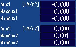
91 15.3 Changing the Displayed Items for High Speed Data Capturing Page 2 Example Page 3 Example (Page 3 can only be selected on models with the /MTR or /AUX option.) Speed, Torque, and Pm are displayed on models with the /MTR option. Aux1 and Aux2 are displayed on models with the /AUX option. Page 4 Example (Page 4 can only be selected on models with the /MTR or /AUX option.) Speed, Torque, and Pm are displayed on models with the /MTR option. Aux1 and Aux2 are displayed on models with the /AUX option. 15-7
92 15.3 Changing the Displayed Items for High Speed Data Capturing ELEMENT Key 3. Press ESC to clear the menu. Displayed in the upper left of the numeric data display screen Voltage measurement range and measurement mode Current measurement range and measurement mode Changing the Element and Wiring Unit (Horizontal direction) 4. Use the cursor keys ( ) to select the column that you want to change. 5. Press the ELEMENT key for displaying numeric data to select the element and wiring unit that you want to display. In high speed data capturing, the elements and wiring unit configurations are the same on all four pages. If you change the element and wiring unit configuration on one page, the configuration changes on the other pages as well. Cursor keys ELEMENT key for displaying numeric data PAGE keys 15-8
93 15.4 Starting and Stopping High Speed Data Capturing This section explains how to start and stop high speed data capturing. Starting and Stopping High Speed Data Capturing (Start/Stop) in the features guide CAUTION During high speed data capturing and when captured data is being saved, the storage medium is constantly being accessed, even though the icon that indicates this ( ) is not displayed. Do not remove the USB memory device or turn the power off. Doing so may damage the storage medium and corrupt its data. During high speed data capturing, HS State: Start appears in the upper right of the screen. While the captured data is being saved, File State: Rec appears in the upper left of the screen. French ATTENTION Pendant la collecte de données haute vitesse et lorsque les données collectées sont enregistrées, le système a constamment accès au support de stockage, même si l icône qui l indique ( ) n est pas affichée. Ne retirez pas le support de stockage USB et ne coupez pas l alimentation. Vous risqueriez d endommager le support de stockage et les données qu il contient. Lors de la collecte des données haute vitesse, «HS State: Start» s affiche dans l angle supérieur droit de l écran. Lorsque les données collectées sont enregistrées, «File State: Rec» s affiche dans l angle supérieur gauche de l écran. 15-9
94 15.4 Starting and Stopping High Speed Data Capturing 1. Follow the procedure in section 15.1 to select High Speed Data Capturing on the Others menu. HS Settings Menu 2. Press FORM to display the following menu. Starts high speed data capturing High speed data capturing starts according to the specified number of data captures (see section 15.1), the capture control settings (see section 15.1), and the save conditions (see section 15.2). When high speed data capturing is started, HS State: Start appears in the upper right of the screen. When the captured data is being saved, File State: Rec appears in the upper left of the screen. Stops high speed data capturing After the specified number of data captures have been made, high speed data capturing automatically stops. To force high speed data capturing to stop, press this soft key. When high speed data is stopped, HS State: Ready appears in the upper right of the screen. Note You cannot restart high speed data capturing without first stopping high speed data capturing. After you stop high speed data capturing and then change the settings or restart high speed data capturing, the data captured up to that point is deleted
95 Chapter 16 Storing Data 16.1 Configuring Storage Control This section explains the following settings for storage control: Storage mode Storage count Confirming and optimizing the maximum storage count Storage interval Scheduled times for real-time storage Trigger event (synchronization to a user-defined event) Storage of numeric data when storage starts Storage Control (Control Settings) in the features guide Control Settings Menu Press SHIFT+STORE START (STORE SET) and then the Control Settings soft key to display one of the menus shown below. The menu that appears varies depending on the storage mode setting that you have specified. Manual Storage Mode Set Store Mode to Manual. Set the storage count (Infinite, 1 to ). Confirms and optimizes the maximum storage count Set the storage interval. Select whether to store numeric data when storage starts. This soft key is displayed when Interval is set to a value other than 00 : 00 : 00. Confirming and Optimizing the Maximum Storage Count Press the Optimize Count soft key to display the following screen. Sets the storage count The storage count is set to the maximum storage count displayed to the left. Maximum storage count (0 to the maximum number of times that data can be stored to the save destination) * * The maximum number of times that storage can be performed depends on the number of stored items that you have set and the free space at the save destination. For details on how to set the stored items, see section For details on how to set the save destination, see section Even if you have specified a USB memory device as the save destination, if you remove the USB memory device, the save destination switches automatically to the internal RAM disk. If you close this screen and then open it again by pressing the Optimize Count soft key, the maximum storage count changes to the value determined by the internal RAM disk, s free space. Setting the Storage Interval Press the Interval soft key to display the following screen. Set the storage interval (00 hours : 00 minutes : 00 seconds to 99 hours : 59 minutes : 59 seconds). 16-1

96 16.1 Configuring Storage Control Scheduled Times for Real-Time Storage Mode Set Store Mode to Real Time. Set the storage count (Infinite, 1 to ). Confirms and optimizes the maximum storage count previous page Set the storage interval. previous page Set the scheduled times for real-time storage. Select whether to store numeric data when storage starts. This soft key is displayed when Interval is set to a value other than 00 : 00 : 00. Setting Scheduled Times for Real-Time Storage Press the Real-time Control soft key to display the following screen. Scheduled storage stop time Scheduled storage start time Set the scheduled start and stop times (Year/month/day, 00 hours : 00 minutes : 00 seconds to 23 hours : 59 minutes : 59 seconds). Sets the scheduled storage start time to the current time Copies the scheduled storage start time to the scheduled storage stop time Integration-Synchronized Storage Mode Set Store Mode to Integ Sync. Set the storage count (Infinite, 1 to ). Confirms and optimizes the maximum storage count previous page Set the storage interval. previous page Select whether to store numeric data when storage starts. 16-2
97 16.1 Configuring Storage Control Event-Synchronized Storage Mode Set Store Mode to Event. Set the storage count (Infinite, 1 to ). Confirms and optimizes the maximum storage count page 16-1 Select the trigger event (Event 1 to Event 8). When measured data is updated, storage is started if the conditions of the specified user-defined event are met. Single-Shot Storage Mode Set Store Mode to Single Shot. Set the storage count (Infinite, 1 to ). Confirms and optimizes the maximum storage count page
98 16.2 Setting the Numeric Data Items to Store This section explains how to set the numeric data items to store. Numeric data items to store Numeric data items that are displayed on the screen Numeric data items specified on the stored item setup screen Stored Items (Item Settings) in the features guide Item Settings Menu Press SHIFT+STORE START (STORE SET) and then the Item Settings soft key to display the following menu. Stores the numeric data that is displayed on the screen Press this soft key to store the numeric data items that are displayed on the screen. Stores the numeric data that you have specified on the Store Items setup screen Press this soft key to store the numeric data items that you have specified on the Store Items setup screen that is displayed when you press the Items soft key. Set the stored items. This soft key is displayed when you select Selected Items. Setting Stored Items (Items) Press the Items soft key to display the following screen. When you press the Selected Items soft key on the Item Settings menu, the numeric data items that you have specified on the following screen are stored. Selects all the numeric data items Clears the selection of all the numeric data items Selects the preset numeric data items Select the check boxes for the numeric items that you want to store. 16-4
 in the features guide File Settings Menu Press SHIFT+STORE START (STORE SET) and then the")

99 16.3 Configuring the Save Conditions of Stored Numeric Data This section explains the following settings for the save conditions of stored numeric data: Save destination Selecting whether to perform automatic CSV conversion when storage stops Auto naming File name Comment Save Conditions (File Settings) in the features guide File Settings Menu Press SHIFT+STORE START (STORE SET) and then the File Settings soft key to display the following menu. Set the save destination and perform manual CSV conversion. Select whether to perform automatic CSV conversion when storage stops. Set auto naming. section 17.2 Set the file name. section 17.2 Set a comment. section 17.2 Setting the Save Destination and Performing Manual CSV Conversion Press the File List soft key to display the following screen. Set the save destination. * When storage starts (see section 16.4), storage data is saved to the specified file name at the specified save destination. * You cannot specify a network drive as the save destination. Executes the manual CSV conversion Select the storage data file (.WTS file) that was saved, and then press the CSV Convert soft key to create a storage data file in ASCII format. 16-5
100 16.4 Starting, Stopping, and Resetting Storage This section explains how to start, stop, and reset storage. Starting, Stopping, and Resetting Storage (STORE START, STORE STOP, and STORE RESET) in the features guide CAUTION During storage, the storage medium is constantly being accessed, even though the icon that indicates this ( ) is not displayed. Do not remove the USB memory device or turn the power off. Doing so may damage the storage medium or corrupt its data. Storage is in progress when the STORE START key is illuminated or blinking or when the STORE STOP key is blinking. French ATTENTION Pendant la collecte, le système a constamment accès au support de stockage, même si l icône qui l indique ( ) n est pas affichée. Ne retirez pas le support de stockage USB et ne coupez pas l alimentation. Vous risqueriez d endommager le support de stockage ou les données qu il contient. Le stockage est en cours quand la touche STORE START est éclairée ou quand elle clignote, ou bien quand la touche STORE STOP clignote. Starting the Storage Operation Press STORE START. This instrument starts storage using the storage mode that you have specified (see section 16.1). The STORE START key is illuminated. Storage has started; Store: Start is displayed. * The STORE START key is blinking. The storage operation is ready; Store: Ready is displayed. * * Character strings are displayed in the upper left of the screen. Stopping the Storage Operation This instrument automatically stops storage according to the storage mode that you have specified. To pause storage, press STORE STOP. The STORE STOP key is blinking. Storage has been paused; Store: Stop is displayed. * If you press STORE START when Stop is displayed in yellow, you can resume the storage operation from the point where you stopped the storage operation. The STORE STOP key is illuminated. Storage has been automatically stopped; Store: Close is displayed, and then Store:Cmpl is displayed. * * Character strings are displayed in the upper left of the screen. 16-6
101 Resetting the Storage Operation Press SHIFT+STORE STOP (STORE RESET). The STORE STOP key turns off. If the storage operation has been paused This instrument finishes writing stored data to a file and closes the file. If the storage operation has automatically stopped When the storage operation stops automatically, this instrument finishes writing stored data to a file and closes the file. Therefore, the reset operation performs no file operations. Note If you do not reset storage, you will not be able to start it again Starting, Stopping, and Resetting Storage 16-7
102 Chapter 17 Saving and Loading Data 17.1 Connecting USB Memory Devices This section explains how to connect USB memory devices to save and load data. If you want to use a storage device on your network (a network drive), you have to use an Ethernet cable to connect this instrument to the network. For details, see section Storage Media in the features guide CAUTION Do not remove the USB memory device or turn off the power when the USB memory device is being accessed. Doing so may damage the storage medium or corrupt its data. When the USB memory device is being accessed, is displayed in the center of the top part of the screen and the USB memory device indicator blinks. French ATTENTION Lorsque le dispositif accède au support de stockage USB, ne retirez pas ce dernier et ne mettez pas l alimentation hors tension. Vous risqueriez d endommager le support de stockage ou les données qu il contient. Quand le système accède au support de stockage USB, s affiche au centre, dans la partie supérieure de l écran, et le voyant du support de stockage USB clignote. USB Memory Devices That Can Be Used and How to Connect USB Memory Devices Use portable USB memory devices that are compatible with USB Mass Storage Class version 1.1. Connect USB memory devices directly to the USB ports (type A) for connecting peripheral devices on the front panel. Hot-plugging is supported: you can connect or disconnect the USB device at any time, regardless of whether this instrument is on or off. When the power is on, this instrument automatically detects the USB memory device after it is connected. This instrument has two USB ports: USB-0 and USB-1. The port numbers are not fixed. The port at which the first USB memory device is detected becomes USB-0. The port at which the second USB memory device is detected becomes USB-1. USB memory device 17-1
103 17.1 Connecting USB Memory Devices Note Connect USB memory devices directly to the USB ports (type A) for connecting peripheral devices. Do not connect them through a hub. Use portable USB memory devices that are compatible with USB Mass Storage Class version 1.1. Do not connect an incompatible USB memory device. You cannot use protected USB memory devices (such as those that contain encrypted content). Do not connect and disconnect the two USB devices repetitively. Provide at least a 10-second interval between removal and connection. General USB Handling Precautions Follow the general handling precautions that are included with your USB memory. 17-2
. Set the file name.")
104 17.2 Saving Setup Parameters This section explains the following settings for saving setup parameters: Save destination Auto naming File name Comment Saving Setup Data (Save Setup) in the features guide Save Setup Menu Press FILE and then the Save Setup soft key to display the following menu. Set the save destination. Set the auto naming method (OFF, Numbering, Date). Set the file name. You can set the file name that is used when Auto Naming is set to OFF. This is also used as the common file name when Auto Naming is set to Numbering. Set a comment. Saves the data Setting the Save Destination (File List) Press the File List soft key to display the following screen. File list The destination storage medium (drive) or folder Use the cursor keys ( ) to move the cursor, and press SET to select the destination. Operation menu Note For details on how to move between the operation menu and the file list and how to operate the operation menu, see section
105 17.2 Saving Setup Parameters Setting Auto Naming (Auto Naming) OFF: The auto naming feature is not used. The name that you specified for the File Name setting is used. If there is a file with the same name in the save destination folder, you cannot save the data. Numbering: This instrument automatically adds a four-digit number from 0000 to 0999 after the common name that you specified for the File Name setting and saves the file. Date: The file name is the date and time (down to seconds) when the file is saved. The file name that you specified for the File Name setting is ignored _121530_0 (2010/09/30 12:15:30) Y M D H Min S The sequence number (0-9, A-Z) that is appended if a file name with the exact same date and time (down to seconds) exists. The sequence number that comes after the date and time is appended if a file name with the exact same date and time (down to seconds) exists. The sequence number is incremented by one (0 to 9 and then A to Z) each time a file is added. Setting the File Name (File Name) You can set the file name that is used when Auto Naming is set to OFF. This is also used as the common file name when Auto Naming is set to Numbering. The maximum number of characters that you can use for file names and folder names is 32 characters. However, there are limitations on the type of characters and the character strings that you can use. Setting the Comment (Comment) You can add a comment that consists of up to 30 characters when saving files. You do not have to enter a comment. All characters, including spaces, can be used in comments. 17-4
106 17.3 Saving Waveform Display Data This section explains the following settings for saving waveform display data: Save destination Auto naming File name Comment Saving Waveform Display Data (Save Wave) in the features guide Save Wave Menu Press FILE and then the Save Wave soft key to display the following menu. Set the save destination. section 17.2 Set auto naming. section 17.2 Set the file name. section 17.2 Set a comment. section 17.2 Saves the data 17-5
107 17.4 Saving Numeric Data This section explains the following settings for saving numeric data: Save destination Numeric data items to save Auto naming File name Comment Saving Numeric Data (Save Numeric) in the features guide Save Numeric Menu Press FILE and then the Save Numeric soft key to display the following menu. Set the save destination. section 17.2 Set the numeric data items to save. Set auto naming. section 17.2 Set the file name. section 17.2 Set a comment. section 17.2 Saves the data Setting the Numeric Data Items to Save (Item Settings) Press the Item Settings soft key to display the following menu. Saves the numeric data that is displayed on the screen Press this soft key to save the numeric data items that are displayed on the screen. Saves the numeric data that you have specified on the File Items setup screen Press this soft key to save the numeric data items that you have specified on the File Items setup screen that is displayed when you press the Items soft key. Set the items to save. This soft key is displayed when you select Selected Items. 17-6

108 Setting Items to Save (Items) Press the Items soft key to display the following screen. When you press the Selected Items soft key on the menu on the previous page, the numeric data items that you have specified on the following screen are saved. Selects all the numeric data items Clears the selection of all the numeric data items Selects the preset numeric data items 17.4 Saving Numeric Data Select the check boxes for the numeric items to save. 17-7
 in the features guide Load Setup Menu Press FILE and then the Load Setup soft key to display the following screen. Select the.set file that you want to load.")
109 17.5 Loading Setup Parameters This section explains how to load setup parameters. Loading Setup Data (Load Setup) in the features guide Load Setup Menu Press FILE and then the Load Setup soft key to display the following screen. Select the.set file that you want to load. Loads the file Note This instrument cannot load setup parameters that have been saved by a product with an incompatible firmware version. This instrument cannot load setup parameters that were saved by an instrument with a different element configuration or with different options. 17-8
 Deleting files and folders Renaming files and folders Making folders (directories) Copying files and folders")
110 17.6 File Operations This section explains the file list s operation menu and the FILE_Utility menu. Sorting the file list Display format Type of file to list Changing storage media (drives) Deleting files and folders Renaming files and folders Making folders (directories) Copying files and folders Moving files and folders Selecting files and folders (All Set, All Reset, and Set/Reset) File Operations (Utility) in the features guide The File List (File List) Path Available memory Selection mark If you want to perform an operation on a group of files at the same time, move the cursor to a file that you want to select, and then press SET to display this mark next to the file. To select multiple folders, press the Set/Reset soft key on the FILE_Utility menu to display this mark next to the selected folder. If you want to perform an operation on a single file, move the cursor to the file you want to select to display this mark next to the file. Operation menu cursor Use the cursor keys ( ) to move the cursor. Sorts the file list Set the display format. Set the type of file to list. Changes the storage medium (drive) Deletes the selected files and folders Renames files and folders Makes folders (directories) Copies the selected files and folders Moves the selected files and folders Total number of files and folders that are contained within the storage medium or folder indicated by the path File list cursor Use the cursor keys ( ) to move the cursor. Operation menu File list Use the cursor keys ( ) to switch between operation areas. 17-9

 Set the display format.")
111 17.6 File Operations Sorting the File List (Sort To) Select Sort To on the operation menu to display the following screen. Sorts by file name in ascending order Sorts by file name in descending order Sorts by file size in ascending order Sorts by file size in descending order Sorts by date and time in ascending order Sorts by date and time in descending order Setting the Display Format (, ) Select or on the operation menu to display the following screen. List Display ( ) Set the display format. Thumbnail Display ( ) Set the display format
112 17.6 File Operations Setting the Type of Files to List (Filter) Select Filter on the operation menu to display the following screen. Set the type of file to list. File Type *. * All files *.SET Setup parameter files *.CSV Numeric data files (ASCII format), storage data files (ASCII format), and waveform display data files (ASCII format) *.WTS Storage data files (binary format) *.HDS Storage header files (binary format) *.BMP Screen image data files (BMP format) and custom display background files *.PNG Screen image data files (PNG format) *.JPG Screen image data files (JPEG format) *.TXT Custom display configuration files Changing the Storage Medium or Drive (Change Drive) Select Change Drive on the operation menu to display the following screen. Changes the storage medium (drive) Storage Medium (Drive) Type RAM-0 Internal RAM disk of this instrument USB-0 USB memory device that was detected first USB-1 USB memory device that was detected second Network Network drive Note You can also change the storage medium by highlighting the storage medium (drive) you want to change to in the file list and pressing SET


113 17.6 File Operations Deleting Files and Folders (Delete) 1. Select the file or folder in the file list that you want to delete. 2. Select Delete on the operation menu to display the following screen. Deletes the selected files and folders File that you want to delete Confirms the deletion of files and folders Note To delete multiple files or folders that are in the file list at the same time, move the cursor to the file or folder that you want to delete, and then carry out the following operations. Files: Press SET or the Set/Reset soft key on the Utility menu. Folders: Press the Set/Reset soft key on the Utility menu. If you press SET, all the files and folders that you have selected up to that point will be cleared. You cannot delete folders on network drives. Renaming Files and Folders (Rename) 1. Select the file or folder in the file list that you want to rename. 2. Select Rename on the operation menu to display the following screen. Use the keyboard to input the new file or folder name. Renames files and folders File that you want to rename. Press ENTER on the keyboard or the ENTER soft key to confirm the entered name
 Press ENTER on the keyboard or the ENTER soft key to confirm the entered name.")
114 Making Folders (Directories; Make Dir) 1. Select the drive or folder in the file list that you want to make the new folder in. 2. Select Make Dir on the operation menu to display the following screen File Operations Use the keyboard to enter the new folder name. Makes folders (directories) Press ENTER on the keyboard or the ENTER soft key to confirm the entered name. Copying Files and Folders (Copy) 1. Select the file or folder in the file list that you want to copy. 2. Select Copy on the operation menu to display the following screen. File list that you are copying from File list that you are copying to Copies the selected files and folders (Copy) Folder that you are copying to Executes the copy operation on the selected files and folders (Copy Exec) 3. Select the drive or folder in the file list that you are copying to. 4. Select Copy Exec on the operation menu to display the following screen. Confirms the copying of files and folders Note The procedure for selecting multiple files or folders at the same time to copy them is the same as the procedure for selecting multiple files or folders at the same time to delete them. For more details, see the note on page You cannot copy folders on a network drive. You can perform file operations on the file list that you are copying to as well
 Executes the move operation on the selected files and folders (Move Exec)")
115 17.6 File Operations Moving Files and Folders (Move) 1. Select the file or folder in the file list that you want to move. 2. Select Move on the operation menu to display the following screen. File list that you are moving data from File list that you are moving data to Moves the selected files and folders (Move) Executes the move operation on the selected files and folders (Move Exec) Folder that you are moving data to 3. Select the drive or folder in the file list that you are moving to. 4. Select Move Exec on the operation menu to display the following screen. Confirms the moving of files and folders Note The procedure for selecting multiple files or folders at the same time to move them is the same as the procedure for selecting multiple files or folders at the same time to delete them. For more details, see the note on page You cannot move folders on a network drive. You can perform file operations on the file list that you are moving data to as well

.")
116 17.6 File Operations FILE Utility Menu Press FILE and then the Utility soft key to display the following menu. Set the file operation (Delete, Rename, Make Dir, Copy, Move). Selects files and folders or clears the selection Additional File Operations Setup Menu Selects all files and folders or clears all the selections Jumps to the specified file or folder Displays the additional file operations setup menu Executes the specified file operation Sorts the file list (By Name, By Size, By Date) Set the display format (, ). Set the type of file to list ( *. *, *.SET, *.CSV, *.WTS, *.HDS, *.BMP, *.PNG, *.JPG, *.TXT). Changes the storage medium (drive) (RAM, USB-0, USB-1, Network) Setting the File Operation (Operation, More) You can perform the same file operations as those that you can perform from the operation menu described on pages 17-8 to Select/Clear (Set/Reset) This soft key selects the file or folder in the file list that is highlighted or clears the selection. The selection marks (see page 17-8) are displayed to the left of the selected files. Select All and Clear All (All Set and All Reset) All Set: In the file list, when a drive is highlighted or a file or folder in a drive or folder is highlighted, pressing this soft key selects all the files and folders in the corresponding drive or folder. The selection marks (see page 17-8) are displayed to the left of the selected files and folders. All Reset: Pressing this soft key clears all the selected files and folders. Jump to the Specified File or Folder (Jump To) Press this soft key to move the cursor to the file or folder in the file list that you specify by its position number. The top-most position in the file list is number 0. Range: However, if you specify a position whose number is larger than the total number of files and folders in the file list, the cursor will move to the bottom-most file or folder in the file list
117 Chapter 18 Saving Screen Images 18.1 Saving Screen Images This section explains the following settings for saving screen images: Save destination File format Color Auto naming File name Comment Saving Screen Images in the features guide Image Save Menu Press SHIFT+IMAGE SAVE (MENU) to display the following menu. Set the save destination. section 17.2 Set the data format (BMP, PNG, JPEG). Set the color (OFF, Color, Reverse, Gray). Set auto naming. section 17.2 Set the file name. section 17.2 Set a comment. section 17.2 Saving Screen Captures Press IMAGE SAVE to save the screen image with the save conditions that you specified on the Image Save menu. 18-1
118 Chapter 19 Printing Screen Images and Numeric Data (Option) 19.1 Loading Roll Paper into the Built-In Printer (Option) This section explains how to load roll paper into the optional built-in printer. Printer Roll Paper Only use roll paper specifically made for use with this instrument. When you first use the printer, use the included roll paper. When you need a new supply of roll paper, contact your nearest YOKOGAWA dealer. Part Number: Specifications: Minimum Quantity: B9316FX Heat sensitive paper, 10 m 10 rolls Handling Roll Paper The roll paper is made of heat sensitive paper that changes color thermochemically. Please read the following information carefully. Storage Precautions When in use, the heat-sensitive paper changes color gradually at temperatures of approximately 70 C or higher. The paper can be affected by heat, humidity, light, and chemicals, whether something has been recorded on it or not. As such, please follow the guidelines listed below. Store the paper in a cool, dry, and dark place. Use the paper as quickly as possible after you break its protective seal. If you attach a plastic film that contains plasticizing material, such as vinyl chloride film or cellophane tape, to the paper for a long time, the recorded sections will fade due to the effect of the plasticizing material. Use a holder made of polypropylene to store the roll paper. When pasting the record paper to another material, do not use paste that contains organic solvents such as alcohol or ether. Doing so will change the paper s color. We recommend that you make copies of the recordings if you intend to store them for a long period of time. Because of the nature of heat-sensitive paper, the recorded sections may fade. Handling Precautions Use genuine, YOKOGAWA-supplied roll paper. If you touch the roll paper with sweaty hands, there is a chance that you will leave fingerprints on the paper, thereby blurring the recorded sections. If you rub something against the surface of the roll paper, the paper may change color due to frictional heat. If the roll paper comes into contact with products such as chemicals or oil, there is a chance that the paper will change color or that the recorded sections will disappear. 19-1
119 19.1 Loading Roll Paper into the Built-In Printer (Option) Loading the Roll Paper WARNING A roll paper cutter is present inside the printer unit cover. Be careful of the cutter so as to avoid injuring your fingers or hands. Do not insert your fingers into the opening on the printer unit (the roll paper ejection hole). When you have opened the printer unit cover to place roll paper in the holder, avoid touching the cutter with your fingers and hands. Do not touch the print head and print motor. If you do, you may burn yourself. French AVERTISSEMENT Un dispositif de coupe de papier en rouleau est fixé sur le couvercle de l imprimante. Prendre garde de se blesser les mains ou les doigts avec le dispositif de coupe. Ne pas insérer de doigt dans l ouverture de sortie du papier en rouleau de l imprimante. Ne pas laisser une main ou des doigts entrer en contact avec le dispositif de coupe lors de l ouverture du couvercle de l imprimante et de la charge du papier en rouleau dans son logement. Ne touchez pas la tête d impression ni le moteur d impression. Vous pourriez vous brûler. 1. Slide the lever to the right to make the printer unit protrude from this instrument. 2. Insert your finger into the groove on the right side of the printer unit. Groove Printer unit Lever 3. Hold the top, bottom, and right side of the printer unit, and then pull it toward you until it stops (pull the unit approximately 5 cm). 4. Hold the left and right sides of the printer unit s tray with your hands, and push the right and left sides of the front of the cover with your thumbs to raise it. Cover Hold the cover as indicated in the figure, and push the cover up. Hold the top, bottom, and right side of the printer unit. Tray 19-2
120 19.1 Loading Roll Paper into the Built-In Printer (Option) 5. Pull approximately 10 cm of the roll paper out, and load the roll paper in the holder so that the thermal side of the paper is facing up. Load the paper so that it passes through the guides. Roll paper Guide Holder Load the roll paper into the holder so that the thermal side of the paper is facing up. 6. Lower the cover while you push the stopper to the left to release the latch. Hold the tray from underneath with both hands, and close the cover until you hear a click. Cover Stopper Push the stopper to the left to release the latch. Close the cover until you hear a click. Tray Cover 7. Push the printer unit (push the area to the left of the lever on the front panel) back into this instrument until you hear a click. Push the printer unit until you hear a click. This completes the procedure for loading the roll paper. Lever 19-3
121 19.1 Loading Roll Paper into the Built-In Printer (Option) Feeding Paper Press SHIFT+PRINT (MENU) to display the following menu. Feeds paper Each time that you press this soft key, this instrumentfeeds approximately 3 cm of the roll paper. Cutting Roll Paper After you load roll paper and close the cover or after you print measured data, to cut the roll paper, pull the paper up against the top of the cover. Note If you open the printer cover immediately after you cut the roll paper, repeat steps 5 to 7 on pages 19-2 and After you load roll paper and close the cover, check whether the paper feeds correctly. If the roll paper does not feed straight, repeat steps 1 to 7 on pages 19-2 and If you load the roll paper backwards, the paper may not feed properly or data may not be printed. This is because the print head doesn t come into contact with the thermal side of the paper. Load the roll paper into the holder in the proper orientation. 19-4
, and printing data when printing starts Comment Feeding paper Printing")
122 19.2 Printing Using the Built-in Printer (Option) This section explains the following settings for printing on the optional built-in printer: Output format Executing auto printing Auto printing Print mode, print count, print interval, scheduled times for real-time printing, trigger event (synchronized to a user-defined event), and printing data when printing starts Comment Feeding paper Printing Screen Images and Numeric Data (Option) in the features guide Print Menu Menu Press SHIFT+PRINT (MENU) to display the following menu. Set the output format (Screen, List). Turns auto printing on (executes auto printing) Configure auto printing. Set a comment. section 17.2 Feeds paper section
123 19.2 Printing Using the Built-in Printer (Option) Configuring Auto Printing Press the Auto Print Settings soft key to display one of the menus shown below. The menu that appears varies depending on the Print Mode setting that you have specified. Interval Print Mode Set Print Mode to Interval. Set the print count (Infinite, 1 to 9999). Set the print interval. Select whether to print the data at print start Setting the Print Interval Press the Print Interval soft key to display the following screen. Set the print interval (00 hours : 00 minutes : 10 seconds to 99 hours : 59 minutes : 59 seconds). Scheduled Times for Real-Time Print Mode Set Print Mode to Real Time. Set the print count (Infinite, 1 to 9999). Set the print interval Interval Print Mode above Set the scheduled times for real-time printing. Select whether to print the data at print start 19-6
 Scheduled print stop time Scheduled print start time Set the scheduled start and stop times (Year/month/day, 00 hours : 00 minutes : 00 seconds to 23")
124 Setting Scheduled Times for Real-Time Printing Press the Real-time Control soft key to display the following screen Printing Using the Built-in Printer (Option) Scheduled print stop time Scheduled print start time Set the scheduled start and stop times (Year/month/day, 00 hours : 00 minutes : 00 seconds to 23 hours : 59 minutes : 59 seconds). Sets the scheduled print start time to the current time Copies the scheduled print start time to the scheduled print stop time Integration-Synchronized Print Mode Set Print Mode to Integ Sync. Set the print interval Interval Print Mode on the previous page Select whether to print the data at print start Event-Synchronized Print Mode Set Print Mode to Event. Set the print count (Infinite, 1 to 9999). Set the trigger event (Event 1 to Event 8). When measured data is updated, data is printed each time the conditions of the specified user-defined event are met. 19-7
125 19.2 Printing Using the Built-in Printer (Option) Printing Press Print to print data according to the conditions specified in the Print Menu menu. 19-8
126 Chapter 20 Ethernet Communication 20.1 Connecting this instrument to a Network This section explains how to connect this instrument to a network. Ethernet Interface Specifications There is a 1000BASE-T port located on the rear panel of the instrument. Item Specifications Ports 1 Electrical and mechanical IEEE802.3 specifications Transmission system Ethernet (1000BASE-T, 100BASE-TX, 10BASE-T) Communication protocol TCP/IP Supported services FTP server, DHCP, DNS, remote control (VXI-11), SNTP, FTP client, Modbus/ TCP server, and Web server Connector type RJ-45 connector Ethernet port RJ-45 modular jack Items Required to Connect this instrument to a Network Cable Use one of the following types of network cables that supports the data rate of your network. A UTP (Unshielded Twisted-Pair) cable An STP (Shielded Twisted-Pair) cable 20-1
127 20.1 Connecting this instrument to a Network Connection Procedure To Connect to a PC over a Network 1. Turn off this instrument. 2. Connect one end of a UTP (or STP) cable to the ETHERNET 1000BASE-T port on the rear panel. 3. Connect the other end of the UTP (or STP) cable to a hub or router. 4. Turn on this instrument. Hub or router that supports 1000BASE-T PC WT UTP or STP cable (straight cable) To Connect to a PC through a Hub or Router 1. Turn off this instrument and the PC. 2. Connect one end of a UTP (or STP) cable to the ETHERNET 1000BASE-T port on the rear panel. 3. Connect the other end of the UTP (or STP) cable to a hub or router. 4. Connect the PC to the hub or router in the same way. 5. Turn on this instrument. Hub or router that supports 1000BASE-T PC WT UTP or STP cable (straight cable) Note Use a hub or router that supports the data rate of your network. When you connect a PC to this instrument through a hub or router, the PC must be equipped with an auto switching 1000BASE-T/100BASE-TX/10BASE-T network card. Do not connect this instrument to a PC directly. Direct communication without a hub or router is not guaranteed to work. 20-2
 in the features guide Configuring TCP/IP Settings (TCP/IP) Press UTILITY, the Network soft key, and then the TCP/IP soft key to display the")
128 20.2 Configuring TCP/IP Settings This section explains the following TCP/IP settings for connecting this instrument to a network: DHCP IP address, subnet mask, and default gateway DNS Domain name, DNS server IP address, and domain suffix TCP/IP (TCP/IP) in the features guide Configuring TCP/IP Settings (TCP/IP) Press UTILITY, the Network soft key, and then the TCP/IP soft key to display the following screen. Set the DHCP (OFF, ON). Set these when DHCP is set to OFF. IP address Subnet mask Default gateway These are displayed when DNS is set to ON or Auto. Domain name DNS server IP address (1: primary, 2: secondary) Domain suffix (1: primary, 2: secondary) Applies the settings Set the DNS (OFF, ON, Auto). OFF: The DNS is disabled. ON: The DNS is enabled. Set the domain name, and the DNS server s primary and secondary IP addresses and domain suffixes. Auto: The DNS is enabled. Set the domain suffixes. The domain name and the DNS server IP addresses are set automatically. The Auto option is only displayed when DHCP is set to ON. 20-3
129 20.3 Accessing this instrument from a PC (FTP Server) This section explains the following settings for accessing this instrument from a PC on a network: User name Password Timeout FTP client software FTP Server (FTP Server) in the features guide Configuring FTP Server Settings (FTP/Web Server) Press UTILITY, the Network soft key, and then the FT/WebP Server soft key to display the following menu. Set the user name (up to 32 characters). Set the password (up to 32 characters). Set the timeout value (30 to 3600 s). Applies the settings FTP Client Software Start an FTP client on a PC. Enter the user name and password that you entered on the screen shown above to connect to this instrument. Note If you set the user name to anonymous, you can access this instrument without entering a password. 20-4

130 20.4 Monitoring the display of this instrument from a PC (Web Server) This section explains the following settings for accessing this instrument from a PC over a network to show the instrument s display on the PC and remotely controlling the instrument from the PC. User name Password Connecting to the DLM4000 from a PC Web Server (Web Server) in the features guide Configuring Web Server Settings (FTP/Web Server) Press UTILITY, the Network soft key, and then the FTP/Web Server soft key to display the following menu. Set the user name (up to 32 characters). Set the password (up to 32 characters). Applies the settings Note Time Out is a setting used by the FTP server feature. It is not necessary for the Web server feature. 20-5
 3.")

131 20.4 Monitoring the display of this instrument from a PC (Web Server) Connecting to this instrument from a PC 1. Open a Web browser* on a PC that is connected to the network. * Recommended browser: Internet Explorer 9.0 or later 2. Enter the following address. (Type the IP address of this instrument for xxx.xxx.xxx.xxx.) 3. Enter the user name and password that you set on the network setup screen of this instrument, which is shown on the previous page, and connect to this instrument. The following screen appears. Note If you set the user name to anonymous, you can access this instrument without entering a password. Home Screen Information about the instrument is displayed. Control Screen 4. Click the Control tab. The following screen appears. LCD Control panel area Message Refresh screen button Set the resolution. Select LOW ( ) or HIGH ( ). Set the screen refresh interval. Set in the range of 5 to 60 s. Auto refresh start/stop button 20-6
 Link to Yokogawa Test & Measurement website Link to")
132 Links Screen 5. Click the Link tab. The following screen appears Monitoring the display of this instrument from a PC (Web Server) Link to Yokogawa Test & Measurement website Link to Yokogawa Test & Measurement power analyzer website 20-7
 in the features guide Configuring Network Drive (Net")
133 20.5 Connecting to a Network Drive This section explains the following settings for saving and loading various data of this instrument from a network drive (FTP server): FTP server (file server) Login name Password Turning FTP passive mode on and off Timeout Connecting to and disconnecting from a network drive Network Drive (Net Drive) in the features guide Configuring Network Drive (Net Drive) Settings and Connecting to It Press UTILITY, the Network soft key, and then the Net Drive soft key to display the following menu. Set the FTP server s host name. Set the login name (up to 32 characters). Set the password (up to 32 characters). Turns FTP passive mode on and off Set the timeout value (1 to 3600 s). Disconnects this instrument from the network drive (FTP server) Connects this instrument to the network drive (FTP server) 20-8
 Time adjustment SNTP (SNTP) in")
134 20.6 Using SNTP to Set the Date and Time This section explains how to use SNTP to set the date and time of this instrument. SNTP server Timeout Turning automatic adjustment on and off Time difference from Greenwich Mean Time (setting shared with the date and time on the System Config menu) Time adjustment SNTP (SNTP) in the features guide Configuring SNTP Settings (SNTP) Press UTILITY, the Network soft key, and then the SNTP soft key to display the following menu. Configure the SNTP server settings (IP address; host name and domain name can be set when DNS is enabled). Set the timeout value (1 to 60 s). Turns automatic adjustment on and off Set the time difference from Greenwich Mean Time ( 12 hours and 0 minutes to 13 hours and 0 minutes). Executes time adjustment 20-9
 in the features guide System Information List (System Overview) Press UTILITY and then the System Overview soft key to display the following screen.")
135 Chapter 21 Other Features 21.1 Viewing System Information (Overview) This section explains how to view system information of this instrument. Overview (System Overview) in the features guide System Information List (System Overview) Press UTILITY and then the System Overview soft key to display the following screen. Displayed Contents Model Suffix No. Version Element Configuration Options Link Date Product ID Model Suffix code Instrument number Firmware version Input element types Options Date and time that the firmware was created Unique number assigned to each instrument (necessary for the purchase of additional options) 21-1
 in the features guide Utility Menu Press UTILITY to display the following menu.")

136 21.2 Initializing Settings This section explains how to initialize this instrument settings to their factory default values. Initializing Settings (Initialize Settings) in the features guide Utility Menu Press UTILITY to display the following menu. Confirmation to Initialize Settings Initializes the settings Note Only initialize this instrument if you are sure that it is okay for all of the settings to be returned to their initial values. You cannot undo an initialization. We recommend that you save the setup parameters before you initialize this instrument. 21-2
 and USB Keyboard Language (USB Keyboard) in the features guide System Config Menu Press UTILITY and then the System Config soft key to display the following menu.")
137 21.3 Setting the Message, Menu, and USB Keyboard Languages This section explains the settings that you can use to change the message, menu, and USB keyboard languages. Language (Language) and USB Keyboard Language (USB Keyboard) in the features guide System Config Menu Press UTILITY and then the System Config soft key to display the following menu. Set the date and time section 3.4 in the getting started guide, IM WT1801E-03EN Configure the language settings. Set the USB keyboard language (Japanese, English). Configuring the Language Settings Press the Language soft key to display the following menu. Set the menu language (Japanese, English, Chinese, German). Set the message language (Japanese, English, Chinese, German). Note Even if you set the menu or message language to a language other than English, some terms will be displayed in English. 21-3
 in the features guide LCD Menu Press UTILITY, the System Config soft key, and then the LCD soft key to display the following menu.")
. Set the LCD backlight brightness (1 to 10). Configure the display color settings.")
138 21.4 Setting the Screen Brightness and Configuring the Display Color Settings This section explains how to set the screen brightness and configure the display color settings. Adjusting the LCD (LCD) in the features guide LCD Menu Press UTILITY, the System Config soft key, and then the LCD soft key to display the following menu. Turns off the LCD backlight (you can turn on the backlight by pressing any key) Select whether to automatically turn off the LCD backlight. Set the amount of time before the backlight is automatically turned off (1min to 60min). Set the LCD backlight brightness (1 to 10). Configure the display color settings. Configuring the Display Color Settings Press the Color Settings soft key to display the following menu. Sets the graph colors to the default values Sets the graph colors to the classic values Set the graph colors for CH1 to CH16. Set the grid intensity (1 to 8). Set the menu and setup screen background color (Blue, Gray). 21-4
 when the measured pulse frequency is less than the lower limit Decimal point and separator to use when data is saved in ASCII format (.")
139 21.5 Configuring the Environment Settings This section explains the following environment settings: Number of digits of numeric data to display Frequency display value when the measured frequency is less than the lower limit Motor display value (/MTR option) when the measured pulse frequency is less than the lower limit Decimal point and separator to use when data is saved in ASCII format (.CSV) Integration resume action at power failure recovery Menu font size Rounding to zero Environment Settings (Preference) in the features guide Preference Menu Press UTILITY, the System Config soft key, and then the Preference soft key to display the following menu. Set the number of digits of numeric data to display (4digits, 5digits). Set the frequency display value when the measured frequency is less than the lower limit (0, Error). On models with the /MTR option, set the motor display value when the measured pulse frequency is less than the lower limit (0, Error). Set the decimal point and separator to use when data is saved in ASCII format as a.csv file (Period, Comma). Set the integration resume action at power failure recovery (Start, Stop, Error). Set the menu font size (Small, Large). Turns rounding to zero on and off 21-5
 in the features guide Configuring D/A")
140 21.6 Configuring D/A Output Items (Option) This section explains the following settings for D/A output. This feature is available on models with the /DA option. Measurement function Element and wiring unit Harmonic order D/A output range Range mode, range maximum, and range minimum D/A Output (D/A Output Items; option) in the features guide Configuring D/A Output Items Press UTILITY and then the D/A Output Items soft key to display the following screen. D/A output signal name For details on the connector pinout and the D/A output signal assignment, see section 4.6 in the getting started guide, IM WT1801E-03EN. Output item This display changes according to the Function, Element/Σ, and Order settings. Set the measurement function (None, other functions for details on the various measurement functions, see Items That This Instrument Can Measure in the features guide). Set the element and wiring unit (Element 1 to Element 6, ΣA to ΣC). Set the harmonic order (Total, 0 to 500; /G5 or /G6 option). You can set this setting when the measurement function includes a harmonic order. Select the mode of the D/A output range (Fix, Manual). Set the maximum and minimum values of the range ( T to T). These settings can be set when Range Mode is set to Manual. 21-6
141 21.7 Carrying Out Self-Tests (Selftest) This section explains the following settings for testing whether the memory and keys of this instrument are functioning properly: Test item Memory test Key test Operation keys, indicators, and keyboard Self-Test (Selftest) in the features guide Selftest Menu Press UTILITY and then the Selftest soft key to display the following menu. Set the item to test (Memory, Key Board). Executing the Memory Test Set the item to test to Memory. Executes the test 21-7

142 21.7 Carrying Out Self-Tests (Selftest) Executing the Key Test Set the item to test to Key Board. Executing the Keyboard Test Displays the keyboard Executes the key test This self-test tests the panel keys and indicators. 21-8
143 21.8 Performing Zero-Level Compensation This section explains how to perform zero-level compensation. Zero-Level Compensation (CAL) in the features guide Press SHIFT+SINGLE (CAL) to execute zero-level compensation. Note This instrument automatically performs zero-level compensation after you change the measurement range or input filter. To make accurate measurements, we recommend that you execute zero-level compensation after warming up the instrument for at least 30 minutes. If the measurement range and input filter remain the same for a long period of time, the zero level may change due to the changes in the environment. If this happens, we recommend that you execute zerolevel compensation. The integration feature includes an auto calibration feature that automatically performs zero-level compensation. 21-9
 in the features guide Configuring NULL Feature Settings Press SHIFT+NULL (NULL SET) to display the following screen.")
.")
144 21.9 Using the NULL Feature This section explains the following settings for the NULL feature: NULL feature setup method All the signals of a given signal type or the selected signals Enabling and disabling the NULL feature NULL Feature (NULL SET) in the features guide Configuring NULL Feature Settings Press SHIFT+NULL (NULL SET) to display the following screen. Select the setup method of the NULL feature (All, Select). If you select All, the NULL feature is turned on for all the input signals that you can use this screen to set. Set the state of the NULL feature for all the signals of a given signal type (ON, Hold, OFF). For the voltage signals of the installed input elements For the current signals of the installed input elements The motor evaluation input signal setup screen is displayed on models with the /MTR option. For motor evaluation input signals For external signals Set the state of the NULL feature for each signal (ON, Hold, OFF). The external signal setup screen is displayed on models with the /AUX option. Enabling and Disabling the NULL Feature Press NULL to illuminate the NULL key and enable the NULL feature. The NULL value for each signal is used for those signals that have been configured to use the NULL feature. Press NULL again to turn the NULL key off and disable the NULL feature
WT1800. Precision Power Analyzer. IM WT EN 2nd Edition
 WT1800 Precision Power Analyzer 2nd Edition Thank you for purchasing the WT1800 Precision Power Analyzer. This User s Manual explains how to use the WT1800. To ensure correct use, please read this manual
DLM2000 Series. Mixed Signal Oscilloscope. IM E 3rd Edition
 DLM2000 Series Mixed Signal Oscilloscope 3rd Edition Thank you for purchasing the DLM2000 Series Mixed Signal Oscilloscope. This User s Manual explains how to use the DLM2000. To ensure correct use, please
WT1800 PRECISION POWER ANALYZER
 PRECISION POWER ANALYZER Page 1 Page 2 PRODUCT TUTORIAL Table of Contents: A.) Overview & Objectives... B.) Power Meter Connections.. C.) Basic Setup for Power Measurement Initialize Settings Setting Wiring
AQ1200A/AQ1200B/AQ1200C/ AQ1200E/AQ1205A/AQ1205E/ AQ1205F OTDR Multi Field Tester
 User s Manual AQ1200A/AQ1200B/AQ1200C/ AQ1200E/AQ1205A/AQ1205E/ AQ1205F OTDR Multi Field Tester 8th Edition Thank you for purchasing the AQ1200A/AQ1200B/AQ1200C/AQ1200E/AQ1205A/AQ1205E/AQ1205F OTDR (Optical
User s Manual. AQ6150/AQ6151 Optical Wavelength Meter IM AQ EN. 1st Edition
 User s Manual AQ6150/AQ6151 Optical Wavelength Meter 1st Edition Notes Trademarks Revisions Thank you for purchasing the AQ6150/AQ6151 Optical Wavelength Meter. The AQ6150/ AQ6151 is a high-speed wavelength
User s Manual. AQ6150/AQ6151 Optical Wavelength Meter IM AQ EN. 6th Edition
 User s Manual AQ6150/AQ6151 Optical Wavelength Meter 6th Edition Thank you for purchasing the AQ6150/AQ6151 Optical Wavelength Meter. The AQ6150/ AQ6151 is a high-speed wavelength measuring instrument
User s Manual. DL7440/DL7480 Digital Oscilloscope Serial Bus Signal Analysis Function
 User s Manual DL7440/DL7480 Digital Oscilloscope Serial Bus Signal Analysis Function (Includes the I 2 C Bus Signal/CAN Bus Signal/ SPI Bus Signal Analysis Function) Yokogawa Electric Corporation 3rd Edition
User s Manual. CW500Viewer IM CW500-61EN. 2nd Edition
 User s Manual CW500Viewer 2nd Edition Thank you for purchasing the CW500 Power Quality Analyzer. This manual explains the operating procedures of CW500Viewer, a software application included with the CW500.
Multi-batch Function (/BT)
") User s Manual Model GX10/GX20/GP10/GP20/10 Multi-batch Function (/BT) User s Manual IM 04L51B01-03EN 3rd Edition Introduction Thank you for purchasing the SMARTDAC+ GX10/GX20/GP10/GP20 (hereafter referred
User s Manual Model GX10/GX20/GP10/GP20/10 Multi-batch Function (/BT) User s Manual IM 04L51B01-03EN 3rd Edition Introduction Thank you for purchasing the SMARTDAC+ GX10/GX20/GP10/GP20 (hereafter referred
User s Manual. DAQSTATION DX100P/DX200P Communication Interface. IM 04L05A01-17E 4th Edition. Yokogawa Electric Corporation
 User s Manual DAQSTATION DX100P/DX200P Communication Interface * 4 L 5 A 1 1 7 E 0 4 * Yokogawa Electric Corporation 4th Edition Forward Thank you for purchasing the YOKOGAWA DAQSTATION DX100P/DX200P (hereinafter
User s Manual RD-MV1000/RD-MV2000 M st Edition
 User s Manual RD-MV1000/RD-MV2000 1st Edition How to Use This Manual Content Summary This user s manual consists of the chapters listed below. For information about the communication features and the accompanying
Application software CA700 Application
 User s Manual Application software CA700 Application User s Manual 4th Edition This user s manual explains the handling precautions, features, and operating procedures of the CA700 Application. To ensure
DL7200 Digital Oscilloscope CAN Bus Signal Analysis Function
 User s Manual DL7200 Digital Oscilloscope CAN Bus Signal Analysis Function IM 701430-51E Yokogawa Electric Corporation IM 701430-51E 2nd Edition Thank you for purchasing the DL7200 Digital Oscilloscope
User s Manual Power Supply IM E. 5th Edition
 User s Manual 701934 Power Supply 5th Edition Thank you for purchasing the 701934 Power Supply. This user s manual contains useful information about the functions and operating procedures of the 701934
User s Manual Model /436102/436103/436104/436106/ /437102/437103/437104/437106/ /437118/437124
 User s Manual Model 436101/436102/436103/436104/436106/ 437101/437102/437103/437104/437106/ 437112/437118/437124 μr10000/μr20000 SD Memory Card (/EM1 Option) Yokogawa Electric Corporation 2nd Edition Introduction
Power Consumption Measuring Software. This user's manual explains how to operate the Power Consumption Measurement Software.
 User s Manual Power Consumption Measuring Software This user's manual explains how to operate the Power Consumption Measurement Software. Trademarks Microsoft, Windows, Windows Vista, Windows 7, Windows
User s Manual Model FX1002/FX1004/ FX1006/FX1008/FX1010/FX1012 FX1000 Paperless Recorder
 User s Manual Model FX1002/FX1004/ FX1006/FX1008/FX1010/FX1012 FX1000 Paperless Recorder IM 04L21B01-01EN 4th Edition Introduction Thank you for purchasing the FX1002, FX1004, FX1006, FX1008, FX1010, or
XL112, XL114 ポータブルデータロガ
 User's Manual Introduction Thank you for purchasing our XL100 Portable Data Station/Portable Data Logger. This Quick Setup Manual briefly describes the key operations as well as setting examples of the
AQ2200 Series Multi-Application Test System Remote Viewer
 User s Manual AQ2200 Series Multi-Application Test System Remote Viewer 4th Edition Foreword This user's manual contains useful information about the precautions, functions, and operating procedures of
Digital Storage Oscilloscope
 Digital Storage Oscilloscope GDS-3000 Series POWER ANALYSIS MANUAL GW INSTEK PART NO. 82DS-PWR00U01 ISO-9001 CERTIFIED MANUFACTURER April 2011 This manual contains proprietary information, which is protected
Interface Definition RISH EM 2340/1320/30/ _Rev. D - 8/2016
 Interface Definition RISH EM 2340/1320/30/40 1 2-60-006-00-00494_Rev. D - 8/2016 2 Section DIGITAL MULTIFUNCTION INSTRUMENT Contents 1. Introduction Programmable Multi-function Energy Meter Installation
Distributed Power System SA3100 Drive Configuration and Programming
 Distributed Power System SA3100 Drive Configuration and Programming Instruction Manual S-3056-1 Throughout this manual, the following notes are used to alert you to safety considerations:! ATTENTION: Identifies
User's Manual. TA320/TA520 Optical Disk Inter-Symbol Interference Analysis Software. IM E 1st Edition. IM E 1st Edition
 User's Manual TA320/TA520 Optical Disk Inter-Symbol Interference Analysis Software 1st Edition 1st Edition Foreword Notes Trademarks Revisions Thank you for purchasing the Optical Disk Inter-Symbol Interference
WT3000 Manual, Vol 2/3 WT3000. Precision Power Analyzer Communication Interface. IM E 5th Edition
 WT3000 Manual, Vol 2/3 WT3000 Precision Power Analyzer Communication Interface 5th Edition Thank you for purchasing the WT3000 Precision Power Analyzer. This Communication Interface User s Manual describes
User s Manual. Mask Pattern Editor IM B9852UH-01E. 4th Edition
 User s Manual Mask Pattern Editor 4th Edition This user's manual contains useful information about the functions and operating procedures and lists the handling precautions of the Mask Pattern Editor (for
MFT Remote Controller
 User s Manual MFT Remote Controller 1st Edition This user's manual contains useful information about the precautions, functions, and operating procedures of the MFT Remote Controller program that is downloadable
TA320/TA520 Optical Disk Jitter Analysis Software
 User's Manual TA320/TA520 Optical Disk Jitter Analysis Software 1st Edition 1st Edition Foreword Notes Trademarks Revisions Thank you for purchasing the Optical Disk Jitter Analysis Software (704216) for
User s Manual DX1000/DX1000N/DX2000 PROFIBUS-DP (/CP1) Communication Interface
 Communication Interface") User s Manual DX1000/DX1000N/DX2000 PROFIBUS-DP (/CP1) Communication Interface Yokogawa Electric Corporation 3rd Edition Thank you for purchasing Daqstation DX1000, DX1000N, or DX2000 (Hereafter, called
User s Manual DX1000/DX1000N/DX2000 PROFIBUS-DP (/CP1) Communication Interface Yokogawa Electric Corporation 3rd Edition Thank you for purchasing Daqstation DX1000, DX1000N, or DX2000 (Hereafter, called
User s Manual. Please Read before Installation (Combustion Pressure Analysis Software)
") User s Manual Please Read before Installation (Combustion Pressure Analysis Software) Thank you for purchasing the Combustion Pressure Analysis Software. This user s manual explains how to install the
User s Manual Please Read before Installation (Combustion Pressure Analysis Software) Thank you for purchasing the Combustion Pressure Analysis Software. This user s manual explains how to install the
VALCON EasyWriter Ver1.0E Manual
 VALCON EasyWriter Ver1.0E Manual E05172-K00022-00 Published Dec.2010 Ver3-1.03 HKS Co., Ltd. Revision History Revision Date 2008/12/10 First Edition (Ver3-1.01) 2010/4/2 Second Edition (Ver3-1.02) 2010/12/22
DL350 Assistant Software
 User s Manual DL350 Assistant Software 3rd Edition This user s manual explains the functions and operating procedures of the DL350 Assistant Software. To ensure correct use, please read this manual thoroughly
Distributed Power System SB3000 Synchronous Rectifier &RQILJXUDWLRQDQG3URJUDPPLQJ
 Distributed Power System SB3000 Synchronous Rectifier &RQILJXUDWLRQDQG3URJUDPPLQJ Instruction Manual S-3034 Throughout this manual, the following notes are used to alert you to safety considerations:!
User s Manual Model DX1002/DX1004/DX1006/DX1012/ DX1002N/DX1004N/DX1006N/DX1012N Daqstation DX1000/DX1000N
 User s Manual Model DX1002/DX1004/DX1006/DX1012/ DX1002N/DX1004N/DX1006N/DX1012N Daqstation DX1000/DX1000N IM 04L41B01-01E 7th Edition Thank you for purchasing the Daqstation DX1000 (hereafter referred
User s Manual Model DX2004/DX2008/DX2010/DX2020/ DX2030/DX2040/DX2048 Daqstation DX2000
 User s Manual Model DX2004/DX2008/DX2010/DX2020/ DX2030/DX2040/DX2048 Daqstation DX2000 Yokogawa Electric Corporation IM 04L42B01-01E 8th Edition Introduction Thank you for purchasing the Daqstation DX2000
WT310E/WT310EH/WT332E/WT333E
 Digital Power Meter WT310E/WT310EH/WT332E/WT333E Communication Interface 2nd Edition Thank you for purchasing the WT310E, WT310EH, WT332E, or WT333E Digital Power Meter. This Communication Interface User
User s Manual DX1000/DX1000N/DX2000 Custom Display
 User s Manual DX1000/DX1000N/DX2000 Custom Display 3rd Edition Thank you for purchasing DX1000/DX1000N/DX2000 (Hereafter, called DX ). This manual explains the custom display function of DX. Read this
RGM180 Display Series
 Quick Start Guide RGM180 Display Series BG0509 REV.A2 RGM180 QUICKSTART LIMITED WARRANTY The manufacturer offers the customer a 24-month functional warranty on the instrument for faulty workmanship or
3A SERIES MODULAR AC & DC LOADS
 3A SERIES MODULAR AC&DC LOADS Key features: Max. Power 300VA per Module Available Voltage Ranges: 60V, 150V and 300 V AC or DC Max. Current Range 20 A AC or DC Choice of Three Modules Up to 4 Load Inputs
User s Manual Model PBL100 Logic Probe IM E. 4th Edition
 User s Manual Model 701988 PBL100 Logic Probe 4th Edition Foreword Thank you for purchasing the PBL100 100 MHz Logic Probe (Model 701988). This user s manual describes the functions, operating procedures,
A2000 Multifunctional Power Meter Profibus Interface
 Interface Description A2000 Multifunctional Power Meter Profibus Interface 3-349-092-03 12/1.10 Contents 1 General Information... 3 1.1 Interface Hardware...3 1.2 Communications Protocol...4 2 Telegram
PQube 3. Power Quality, Energy & Environment Monitoring. New Low-Cost, High-Precision
 New Low-Cost, High-Precision Power Quality, Energy & Environment Monitoring PQube 3 Power Quality Class A Energy Revenue Grade class 0.2s Accuracy Additional AC, DC, and Environment Sensor Channels World
User s Manual. OPC-UA Server (/E3) GX10/GX20/GP10/GP20/GM10 IM 04L51B01-20EN. 2nd Edition
 GX10/GX20/GP10/GP20/GM10 IM 04L51B01-20EN. 2nd Edition") User s Manual Model GX10/GX20/GP10/GP20/GM10 OPC-UA Server (/E3) 2nd Edition Introduction Thank you for purchasing the SMARTDAC+ GX10/GX20/GP10/GP20 (hereafter referred to as the GX or GP) or the GM.
User s Manual Model GX10/GX20/GP10/GP20/GM10 OPC-UA Server (/E3) 2nd Edition Introduction Thank you for purchasing the SMARTDAC+ GX10/GX20/GP10/GP20 (hereafter referred to as the GX or GP) or the GM.
DRTS 33. The new generation of advanced test equipments for Relays, Energy meters, Transducers and Power quality meters
 The new generation of advanced test equipments for Relays, Energy meters, Transducers and Power quality meters Testing all relay technologies: electromechanical, solid state, numerical and IEC61850 Manual
DRTS 33. The new generation of advanced three phase relay test set
 The new generation of advanced three phase relay test set Testing all relay technologies: electromechanical, solid state, numerical and IEC61850 Local control with color display Simultaneously available:
MIC-2 Multi-instrument DATA SHEET
 Measurements All 3-phase AC measurements True RMS 4-Quadrant energy Power Quality Analysis Replaces analogue meters RS-485 Modbus RTU protocol TCP/IP Modbus (optional) Profibus DP (optional) I/O modules
Operating Instructions Extended Cascade Controller MCO 101
 Operating Instructions Extended Cascade Controller MCO 101 VLT AQUA Drive FC 200 Extended Cascade Controller Option Contents Contents 1. Safety and precautions 3 Safety Instructions 3 Avoid unintended
DNP Points List and Implementation
 S&C IntelliCap Plus Automatic Capacitor Control DNP Points List and Implementation Table of Contents Section Page Section Page DNP Points List for IntelliCap Plus Controls...1 Status Points....2 Analog
User friendly and easy to program
 New Product Digital Panel Meter WPMZ User friendly and easy to program μm m/min mm rpm m/min ton Universal design! New Digital Panel Meter Specification is subject to change without notice Watanabe Electric
Model P4017 Single Channel USB Oscilloscope. Quick Start Guide
 Model P4017 Single Channel USB Oscilloscope Quick Start Guide General Warranty BNC warrants that the product will be free from defects in materials and workmanship for 3 years from the date of purchase
User s Manual X-Wirepuller
 User s Manual X-Wirepuller IM B9852UL-01E 6th Edition Foreword Notes Trademarks Revisions This user's manual contains useful information about the precautions, functions, and operating procedures of the
Waveform Viewer for DL series
 User s Manual Waveform Viewer for DL series Yokogawa Electric Corporation 7th Edition a Foreword Notes Trademarks Revisions Thank you for purchasing the Waveform Viewer (Model 700919) for DL series oscilloscopes.
Additional Device Support in PowerLogic ION Enterprise 6.0
 70072-0191-00 TECHNICAL 06/2009 Additional Device Support in PowerLogic ION Enterprise 6.0 This document outlines support in ION Enterprise 6.0 for devices that are not based on ION architecture. In This
DRTS 64. The new generation of advanced test equipment for Relays, Energy meters, Transducers and Power quality meters.
 The new generation of advanced test equipment for Relays, Energy meters, Transducers and Power quality meters Testing all relay technologies: electromechanical, solid state, numerical and IEC61850 Manual
MIC-2 MKII & MIC-2 MKII DIN, Multi-instrument DATA SHEET
 & DIN, Multi-instrument DATA SHEET Measurements All 3-phase AC measurements True RMS 4-Quadrant energy Power Quality Analysis Replaces analogue meters RS-485 Modbus RTU protocol TCP/IP Modbus (optional)
/21 CLAMP ON POWER
 Established 98 Advanced Test Equipment Rentals www.atecorp.com 800-404-ATEC (83) INSTRUCTION MANUAL 369-0/ CLAMP ON POWER HiTESTER i Contents Contents Introduction... Standard Accessories and Options...
PSL Power Standards Lab 2020 Challenger Drive Alameda, CA USA TEL FAX
 Reading PQube Meters remotely using Modbus-over-TCP PSL Power Standards Lab 2020 Challenger Drive Alameda, CA 94501 USA TEL ++1-510-522-4400 FAX ++1-510-522-4455 www.powerstandards.com 1 October 2010 A
XL100 Portable Data Station Communication Function
 User s Manual XL100 Portable Data Station Communication Function 1st Edition: October 2005 (MC) Introduction Notes Thank you for purchasing our XL100 Portable Data Station. This Communication Function
XMC-24DSI24WRC Wide-Range 24-Bit, 24-Channel, 200KSPS XMC Analog Input Module With 24 Wide-Range (High-Level, Low-Level) Delta-Sigma Input Channels
 Delta-Sigma Input Channels") XMC-24DSI24WRC Wide-Range 24-Bit, 24-Channel, 200KSPS XMC Analog Input Module With 24 Wide-Range (High-Level, Low-Level) Delta-Sigma Input Channels Features Include: 24 wide-range differential 24-Bit simultaneously-sampled
XMC-24DSI24WRC Wide-Range 24-Bit, 24-Channel, 200KSPS XMC Analog Input Module With 24 Wide-Range (High-Level, Low-Level) Delta-Sigma Input Channels Features Include: 24 wide-range differential 24-Bit simultaneously-sampled
DENT Instruments ELITEpro Mobile App
 DENT Instruments ELITEpro Mobile App Version 3.0 Instruction Guide Revision: Final Draft May 20, 2015 Page 2 of 16 Instruction Guide: ELITEpro Mobile App 2015 DENT Instruments, Inc. All rights reserved.
User s Manual. Advanced Security Function (/AS) Data Acquisition System GM IM 04L55B01-05EN. Yokogawa Electric Corporation.
 Data Acquisition System GM IM 04L55B01-05EN. Yokogawa Electric Corporation.") User s Manual Data Acquisition System GM Advanced Security Function (/AS) User s Manual Yokogawa Electric Corporation 4th Edition Introduction Thank you for purchasing the SMARTDAC+ Data Acquisition System
User s Manual Data Acquisition System GM Advanced Security Function (/AS) User s Manual Yokogawa Electric Corporation 4th Edition Introduction Thank you for purchasing the SMARTDAC+ Data Acquisition System
MotionView Configuration and Programming Software USER S MANUAL
 MotionView Configuration and Programming Software USER S MANUAL IM94MV01C Table of Contents 1 MotionView Software Overview......................................... 3 1.1 Installation and Package Revision.................................................
UMG 511. Class A EN UMG 511 Class A power quality analyzer. according to EN50160, IEEE 519, ITIC, IEC Areas of application
 UMG 511 Class A EN 50160 UMG 511 Class A power quality analyzer according to EN50160, IEEE 519, ITIC, IEC 61000-4-30 The UMG 511 power quality analyzer is particularly suitable for monitoring power quality
PQube 3. Power Quality, Energy & Environment Monitoring. New Low-Cost, High-Precision
 Power Sensors Ltd New Low-Cost, High-Precision Power Quality, Energy & Environment Monitoring PQube 3 Power Quality Class A Edition 3 Energy Revenue Grade class 0.2/0.2s Accuracy Additional AC, DC, and
Electromechanical Systems Simulation Software (LVSIM -EMS)
") Electromechanical Systems Simulation Software (LVSIM -EMS) LabVolt Series Datasheet Festo Didactic en 04/2018 Table of Contents General Description 2 Virtual Instrumentation 3 Metering Window 4 Oscilloscope
Electromechanical Systems Simulation Software (LVSIM -EMS) LabVolt Series Datasheet Festo Didactic en 04/2018 Table of Contents General Description 2 Virtual Instrumentation 3 Metering Window 4 Oscilloscope
MIC-2 MKII, Multi-instrument DATA SHEET
 MIC-2 MKII, Multi-instrument DATA SHEET Measurements All 3-phase AC measurements True RMS 4-Quadrant energy Power Quality Analysis Replaces analogue meters RS-485 Modbus RTU protocol TCP/IP Modbus (optional)
Eco-POWER METER Data Collection Software KW Monitor Operation Manual
 Eco-POWER METER Data Collection Software KW Monitor Operation Manual Software version: KW Monitor V2.70 Issued on January 2014 Table of Contents Chapter 1 Introduction...1 Chapter 2 Main functions of KW
RIGOL. Quick Guide. DSA1000 Series Spectrum Analyzer. Nov RIGOL Technologies, Inc
 Quick Guide DSA1000 Series Spectrum Analyzer Nov. 2011 RIGOL Technologies, Inc Copyright 2010 RIGOL Technologies, Inc. All Rights Reserved. Trademark Information RIGOL is registered trademark of RIGOL
Models PEL 102 & PEL 103
 V1 V2 V3 N 1000V CAT III I1 I2 I3 600V CAT IV POWER & ENERGY LOGGER ON/OFF START/STOP Special product features MEASURES '''' ''' D E M A N D $ TRACKS E N E R G Y C O S T POWER QUALITY ANALYZERS, METERS
User s Manual. Wirepuller. Yokogawa Electric Corporation. IM B9852UC-01E 6th Edition
 User s Manual Wirepuller 6th Edition Yokogawa Electric Corporation Foreword Notes Trademarks Revisions This user's manual contains useful information about the precautions, functions, and operating procedures
Three-Phase Power Quality Analyzer PowerPad Model 3945-B
 Three-Phase Power Quality Analyzer PowerPad Model 3945-B Display and record waveforms, transients, trend data and events simultaneously! Wouldn t it be nice if you could look inside your electrical system
Safety Instructions 1-1 Avoid unintended Start General Description 2-2
 Contents Contents 1 Safety and precautions 1-1 Safety Instructions 1-1 Avoid unintended Start. 1-1 2 Introduction 2-1 General Description 2-2 3 Supported Configuration 3-1 Introduction 3-1 Fixed-speed
DG0598 Demo Guide SmartFusion2 Dual-Axis Motor Control Starter Kit
 DG0598 Demo Guide SmartFusion2 Dual-Axis Motor Control Starter Kit Microsemi Corporate Headquarters One Enterprise, Aliso Viejo, CA 92656 USA Within the USA: +1 (800) 713-4113 Outside the USA: +1 (949)
AXF Verification Tool
 User s Manual AXF Verification Tool R3.01 R1.01 2nd Edition Toc-1 AXF Verification Tool 2nd Edition CONTENTS 1 INTRODUCTION... 1-1 1.1 About This Manual...1-2 1.2 Safety and Modification Precautions...
Everything s possible. Modbus Communication. Reference Manual. DigiFlex Performance Servo Drives. MNCMMBRF-02
 Everything s possible. Modbus Communication Reference Manual DigiFlex Performance Servo Drives www.a-m-c.com MNCMMBRF-02 Preface ADVANCED Motion Controls constantly strives to improve all of its products.
FX1000 Communication Interface (/C2, /C3, /C7)
") User s Manual FX1000 Communication Interface (/C2, /C3, /C7) 1st Edition Thank you for purchasing the FX1000 (hereafter referred to as FX ). This User s Manual contains information about the Ethernet/serial
User s Manual FX1000 Communication Interface (/C2, /C3, /C7) 1st Edition Thank you for purchasing the FX1000 (hereafter referred to as FX ). This User s Manual contains information about the Ethernet/serial
GXLink MultiChannel Wave Inserter Model SP-631
 800173-0A Digital High Speed GXLink MultiChannel Wave Inserter Model SP-631 User Manual Copyright 2009 It is prohibited to copy, reproduce or distribute this information in whole or in part without the
MindWare Electromyography (EMG) Analysis User Reference Guide Version Copyright 2011 by MindWare Technologies LTD. All Rights Reserved.
 Analysis User Reference Guide Version Copyright 2011 by MindWare Technologies LTD. All Rights Reserved.") MindWare Electromyography (EMG) Analysis User Reference Guide Version 3.0.12 Copyright 2011 by MindWare Technologies LTD. All Rights Reserved. MindWare EMG 3.0.12 User Guide Internet Support E-mail: sales@mindwaretech.com
MindWare Electromyography (EMG) Analysis User Reference Guide Version 3.0.12 Copyright 2011 by MindWare Technologies LTD. All Rights Reserved. MindWare EMG 3.0.12 User Guide Internet Support E-mail: sales@mindwaretech.com
User s Manual. Wireless Input Unit IM 04L57B01-01EN. 1st Edition
 User s Manual Model GX70SM Wireless Input Unit User s Manual IM 04L57B01-01EN 1st Edition Introduction Thank you for purchasing the SMARTDAC+ Series Wireless Input Unit GX70SM (hereafter referred to by
R Remote Version 4.5 User s Guide
 R Remote Version 4.5 User s Guide Thank you for choosing a Yamaha product. This user s guide explains setup, firmware update and use of "R Remote," a Windows/Mac application that lets you make parameter
PQM - Power Quality Monitoring
 UMG 511 PQM - Power Quality Monitoring Class A power quality analyser according to IEC61000-4-30 The UMG 511 power quality analyser is particularly suitable for monitoring power quality according to standards
ACT-1B Series Panel Tachometer
 MONARCH INSTRUMENT Instruction Manual ACT-1B Series Panel Tachometer Printed in the U.S.A. Copyright 2009 Monarch Instrument, all rights reserved 1071-4843-111R 0909 15 Columbia Drive Amherst, NH 03031
DL350. ScopeCorder. Communication Interface. IM DL350-17EN 3rd Edition
 ScopeCorder DL350 Communication Interface IM DL350-17EN 3rd Edition Thank you for purchasing the DL350 ScopeCorder. This Communication Interface User s Manual explains the following interface features
DX200 OPTIONS INSTRUCTIONS
 DX200 OPTIONS INSTRUCTIONS FOR CMOS SAVE FUNCTION WITH FTP ADVANCED FEATURE OF DX200 EHTERNET FUNCTION Upon receipt of the product and prior to initial operation, read these instructions thoroughly, and
SINGLE-CHANNEL PROCESS CONTROLLERS & TEMP. DISPLAYS D3820/D3830 Series
 The Digitec Series D3800 Panel Meters offer many features and performance capabilities to suit a wide range of industrial applications. The D3820 and D3830 are available in the ranges of 4-20mA, 0-10 VDC,
NP40 - PORTABLE POWER QUALITY ANALYZER FEATURES
 NP40 - PORTABLE POWER QUALITY ANALYZER NP40 power quality analyzer is the professional portable device to measure and analyze the power system quality, supply the harmonics analysis and power quality data
USER MANUAL 2012 V1.1
 SMART MINI POWER SDM630 USER MANUAL 2012 V1.1-1 - Installation and Operation Instructions Important Safety Information is contained in the Maintenance section. Familiarise yourself with this information
User s Manual. Symbol Editor IM B9852US-01E. 11th Edition
 User s Manual Symbol Editor IM 11th Edition Foreword Notes Trademarks Revisions This user's manual describes the Symbol Editor s handling precautions, functions, operating procedures, and other important
User s Manual. FX100(Desktop Type) IM 04L20A01-51E 1st Edition. Yokogawa Electric Corporation. Model FX103/FX106/FX112
 IM 04L20A01-51E 1st Edition. Yokogawa Electric Corporation. Model FX103/FX106/FX112") User s Manual Model FX103/FX106/FX112 FX100(Desktop Type) * 4 L 2 0 A 1 5 1 E 0 1 * Yokogawa Electric Corporation 1st Edition Forword Notes Trademarks Revisions Thank you for purchasing the FX100. This
User s Manual Model FX103/FX106/FX112 FX100(Desktop Type) * 4 L 2 0 A 1 5 1 E 0 1 * Yokogawa Electric Corporation 1st Edition Forword Notes Trademarks Revisions Thank you for purchasing the FX100. This
Portable FFT Analyzer Model CF-7200
 Portable FFT Analyzer Model CF-7200 Vibration analysis procedure This document describes the general operational procedure for vibration analysis to use the NP-3000 series accelerometer. Throughout this
DRTS 66. The new generation of advanced test equipments for Relays, Energy meters, Transducers and Power quality meters
 The new generation of advanced test equipments for Relays, Energy meters, Transducers and Power quality meters Testing all relay technologies: electromechanical, solid state, numerical and IEC61850 Manual
EM QUICK START GUIDE. Quick Start Guide EM BG0504 REV.A2
 Quick Start Guide EM132-133 Mechanical Installation Figure 1: Instrument Dimensions 2 Mechanical Installation Figure 2: Mounting the EM133 on DIN Rail or on flat surface IMPORTANT! Only qualified personnel
User s Manual Model PBL250 Logic Probe IM E. 3rd Edition
 User s Manual Model 701989 PBL250 Logic Probe 3rd Edition Foreword Thank you for purchasing the PBL250 250 MHz Logic Probe (Model 701989). This user s manual describes the functions, operating procedures,
User Manual Australia
 User Manual Australia April 2009 EAZ0057B06A Rev. A Trademarks Acknowledgements Snap-on, ShopStream Connect, ETHOS, MODIS, SOLUS, SOLUS PRO, and Vantage PRO are trademarks of Snap-on Incorporated. All
2U/5U. AC + DC Power Solutions. Transient Generation for Disturbance Tests. only. High Performance Programmable AC Power Source
 AFV-P series High Performance Programmable AC Power Source only 2U/5U i Output Frequency up to 15-1000Hz Intuitive Touch Screen HMI AC Source with DC output AC & DC Transient Generation for Disturbance
Fractional Divider Evaluation Board AD9858FDPCB
 Fractional Divider Evaluation Board AD9858FDPCB INTRODUCTION The AD9858 is a 1 GHz direct digital synthesizer (DDS) featuring a 10-bit DAC, an RF mixer, and on-chip PLL synthesis blocks. Used in conjunction,
STPM32, STPM33, STPM34 Smart Metering ICs. Taking care of every milliwatt
 STPM32, STPM33, STPM34 Smart Metering ICs Taking care of every milliwatt High accuracy down to stand-by mode 2 The STPM32, STPM33 and STPM34, smart metering front end provide two, three and four independent
PRe6. Multi-Channel Analog Pre-Amplifier
 User's Guide and Warranty Information PRe6 Multi-Channel Analog Pre-Amplifier Bel Canto Design, LTD. 212 Third Avenue North Minneapolis, MN 55401 Phone: (612) 317.4550 Fax: (612) 359.9358 www.belcantodesign.com
AE3100 Series User Manual. Version 1.02
 AE3100 Series User Manual Version 1.02 Preface Thanks for purchasing the AE3100 series OTDR (Optical Time Domain Reflectometer). This manual contains useful information about AE3100 series OTDR s functions
3 PHASE POWER ANALYZER
 SD card real time data recorder with harmonic measurement 3 PHASE POWER ANALYZER Model : DW-6095 Your purchase of this 3 PHASE POWER ANALYZER marks a step forward for you into the field of p r e c i s
with Backlight Graphic LCD Screen
 with Backlight Graphic LCD Screen ENERGY AND AUTOMATION POWER OF ENERGY SAVING For the control of energy distribution systems detecting when problems occur that could put the quality and availability of