IDEA. Quick Start Guide
|
|
|
- Myles Jenkins
- 5 years ago
- Views:
Transcription
1 IDEA Quick Start Guide 1. Installation Launching 2. Drawing Walls & Openings 3. Building Elements 4. Inserting Library Drawings 5. Photorealism 6. Walkthrough IDEA 1
2 2 4M
3 Preface This Quick Start Guide provides a fast and friendly introduction on IDEA Architecture main features and functionalities. All the features and functions of the program are presented and explained in detail within the complete User s Guide, along with informative examples. IDEA is an Integrated Workstation for Architectural Building Design, covering all the range of the Architectural needs (model creation, rendering and virtual walkthrough), within a high productivity environment, based on a true model of the building, which is based on an advanced object-oriented technology. Due to this fact, IDEA users can apply all the standard CAD commands (copy, move, trim, extend etc) directly on any building object (walls, openings, beams etc), using at the same time all the known editing facilities (such as grips, right click -> properties etc) and getting the visual transformation of the model in 2D & 3D in real time. This unrestricted "shaping" of the real model concerns both the basic building framework (walls and openings) as well as the more complex building elements (such as slabs of any type, staircases, roofs, rails, ramps etc), all of which are easily manipulated through parametric dialogs and sophisticated shaping algorithms. Furthermore, the program provides rich libraries of practically unlimited types of openings and shutters (generated through a large number of parameters) as well as a large number of drawings, objects and symbols grouped into several categories. As a result, the user may focus on the design and creation, avoiding any time-consuming or boring drawing tasks. Using IDEA, any design ideas can be realized and presented easily and quickly. This Guide is divided into 6 short parts: - Part 1 describes the installation procedure and the main menu structure. - Part 2 describes the basic Architectural Synthesis functions, concerning mainly walls and openings. - Part 3 shows how to create and edit more complex elements such as slabs, roofs, staircases, rails etc. - Part 4 deals with the Library drawings and objects. - Part 5 shows how to obtain a photorealistic result on an IDEA project. - Part 6 describes how easily and quickly a virtual walkthrough is realized. Users are encouraged to consider the contents of this Guide along with the Tutorial, in order to speed up the learning phase. IDEA 3
4 4 4M
, click Next. 3. When the License Agreement appears, read it carefully.")
5 1. Installation - Launching 1.1 Installing IDEA 1. Insert the CD in your computer CD-ROM drive (e.g. D:, E:) or, if you received your software via Internet, run the installation application you downloaded. 2. When the Welcome page appears (as shown below), click Next. 3. When the License Agreement appears, read it carefully. If you agree with the terms, check the respective radio button and then click Next (you must agree with the terms to proceed with the installation). 4. In the next screen enter your username and organization information and check if you want to create a desktop icon. Then click Next to see if the information is correct (see the following window) and finally click Install for the installation procedure to begin. IDEA 5


6 5. Upon completion of the installation procedure, the following last window appears on screen and all needed is to click Finish. In case that the Run IDEA checkbox is selected, the program will start running. 6. After installation, the program is located within the programs list. 6 4M

7 1.2 Start Working with IDEA To execute the program click on the respective desktop icon or select it via Start -> Programs -> IDEA. As soon as the program starts running, the following main menu screen appears: The program interface, as well as its functionality, is quite similar to AutoCAD and 4MCAD. The options and commands of the program menu are grouped into the following basic groups: 1. FILE, group of commands regarding the typical file management options (New Project, Open Project etc). 2. AutoREG, group of commands concerning the design of the Topographical diagram. 3. AutoBLD, group of commands where the main drawing, editing and viewing options regarding the Architectural model can be found. 4. PhotoIDEA, groups of commands where the rendering and photorealism options can be found. 5. WalkIDEA supporting the virtual walkthrough (animation). 6. PLUS, supplementary group of drawing utilities. IDEA 7
8 To start working with IDEA, you should first define a new project using the New Project option, which is found in the FILE group of commands. By selecting this option, the program prompts for the project name (see window). In case that another drawing is already open (even an empty one), then the prompt Ignore changes? (Y/N) might appear. Furthermore, the command Open Project displays an on-screen list with the existing projects in the hard drive. After having defined a new project, or after having selected an existing one, you are ready to begin working. This Quick Start Guide emphasizes mostly on the AutoBLD group of commands, which support the architectural synthesis and building design process. Its concept is based on the principle Set up a building in 3 steps, which is the same to the introduction Tutorial: 1. Draw Walls & Openings 2. Create the building elements (Slabs, Stairs, Roof etc) 3. Locate library drawings and objects Once the project has been completed, then guidelines are also provided on: - How a photorealistic view of the building can be obtained - How a virtual walkthrough can be realized As a result, this Quick Start Guide helps the reader to understand the program philosophy, comprehend its main design functions and significantly speed up the learning process. 8 4M
9 2. Drawing Walls & Openings Regarding the drawing functionality of Walls & Openings, IDEA contains all the commands required for the unrestricted "shaping" of the basic building framework, such as parallel moving of walls, trimming, extending, joining and breaking walls as well as placing openings of any kind on them (windows, sliding doors, openings, arches). During the initial drawing, as well as during any modification at any stage, the drawing is automatically updated (e.g. placing an opening on a wall does not break the wall in two parts, the opening moves easily from side to side whether you are working on the ground-plan or on a 3D view, the wall is restored without leaving undesirable lines after deleting an opening etc). Furthermore, all the necessary readjustments (e.g. dimensioning, opening labels), following each modification, are carried out automatically, so that the user may focus on the Design procedure. 2.1 Drawing Walls The Wall option, located in the second subgroup of the AutoBLD group of commands, includes the Outer, Inner, Outer wall from polyline, Inner wall from polyline and Outline options as well as the option subgroup Modify, Delete, Extend, Break, Join, Trim and Move. The first subgroup concerns the wall drawing, while the second with their further processing after being drawn. Finally, there is also the Elevation of Merge Intersection option, which affects the view plan drawing presentation. By selecting Outer Wall, first of all its attribute dialog appears with a series of parameters (type, dimensions, colors etc), which are described in detail within the User s Guide. IDEA 9
10 In order to start drawing a wall, you should click OK and then follow the instructions shown below: Outer wall (straight / arc): After activating the command (by pressing <Enter> in the menu), you are required to successively provide: i) the starting point of the wall (the application message in the command prompt is: Wall start \ Relative to wall \ Toggle shape <Linear> ii) the ending point of the wall (the application message in the command prompt is Wall end \ Relative to wall \ Toggle shape <Linear> iii) the direction towards which the wall shall grow, by providing any point on one of the two half-planes defined by the wall line (the application message in the command prompt is "Enter Side Point"). After the above actions, you can see that the wall has been drawn and that you can continue to draw another wall starting from the ending point you defined earlier, unless you right click, which means that you want to stop. You can change the wall drawing from linear into circular, typing T in the following programme prompts and pressing <Enter>. During drawing, one can come to the conclusion that the ability of drawing consecutive walls is very convenient, since it saves the user from making many movements. As mentioned further below, in the Element Parameters section, the thickness of the wall, its height and its level in relation to the floor level (when the level is 0, the wall starts from the floor), are stored within the Element Parameters for the wall. By providing proper values for the wall height and level, any possible case of walls of unequal height can be dealt with. Because of their importance, the techniques and tools for creating walls are described here in detail: a) Simple Wall: After defining the first point of a wall, as you are moving to define the second point, in the coordinates system, you can see the length of the wall being drawn as well as the angle towards which it is drawn. You can provide a number for the size of the wall, either in Cartesian or polar coordinates, in the same way as in 4MCAD. For example, if you want to draw a horizontal wall that is 2 meters long, in the command prompt: Wall end/relative to Wall \ Toggle shape <Linear> and then you can see that the wall shown on the right is drawn. 10 4M
11 Nevertheless, if you know the point where the end of the wall lies with respect to the initial point (relative distances Δx and Δy), you can which means that the distance between the first and the second point is 2m along the x-axis and 3m along the y-axis. In this last case, the wall that is drawn is the one shown on the right. b) Connect to another wall: If you want to connect a wall to another wall, you can do so by using the special snap features ("osnap") provided by 4MCAD. In this way, you can activate osnap by pressing the middle button of a 3-button mouse (or by holding <Shift> down and pressing the right button of a 2-button mouse) and either select the end or the middle of a wall or bring the wall in a position vertical to another one or provide the nearest point etc. For example, if you activate the Wall command, define the first starting point of the wall so that it falls exactly upon the bottom right endpoint of the previous one (using osnap "ENDPOINT") and provide the growing side. Then, you can see the two connected walls, as shown in the adjacent example. Moreover, you can join two walls by grabbing one by the grips and moving it onto the point you want on the second wall. Thus, you can move, expand etc walls by using only their grips as if they were simple lines. It is clear that the program can automatically erase the wall joint provided the Cleanup Join option of the External Wall tab is checked. Furthermore, it should be pointed out that the program performs the joint even if there is no grabbed point using "osnap" but one of the points (starting or ending) simply lies within another wall. c) Create a wall in a position relative to another wall: The programme can display the distance from the end of the wall, with which another wall will be connected. More specifically, provided that the Wall option is selected and R (for "relative") is pressed, you are asked to move the mouse and select an existing wall (either from inner or outer side and towards the left or the right side). As soon as this happens, the graphics cursor automatically acquires the direction of the wall and the coordinates on the top of the screen indicate the distance from the end of the previously selected wall. Moreover, the 0 coordinate (that is, the point where the value for distance is zero) is exactly that end of the wall lying towards the side you selected the wall. This way, the newly created wall can have the exact relative distance you want with respect to the other one, with no effort at all. Apparently, this facility (viewing the desired relative distances on the screen during drawing) is extremely useful. Similar operations are applied during drawing inner walls or openings on walls. Outer Wall from Polyline: This option enables the user to specify more than one walls simultaneously or an outlined area (or outline). This command is much alike the Outline option, which is described further down. The only difference is that, using this command, you just have to draw the room outline using a polyline. If you want to close the polyline, just type c (letter c) in the command line; in which case you can see the polyline closing on the screen (that is, the last line is automatically drawn) and the only action left is to specify through a single point the side towards which you want the walls to grow. The programme prompts if you want to delete the polyline used as guide for the wall drawing. IDEA 11
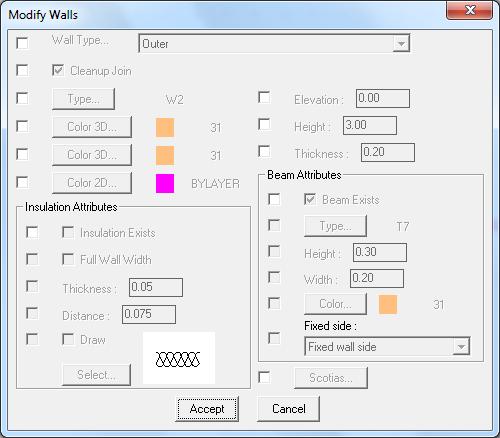
12 Inner Wall: This command is similar to the Outer Wall option. While drawing an inner wall, the facility mentioned above for the outer wall is very helpful. Inner Wall from Polyline: This command is similar to the Outer Wall from Polyline option. Outline: This option enables the user to define simultaneously more than one walls on an outlined area (or outline). Begin by providing consecutively the starting and the ending point of each wall and then the side (outer or inner) towards which you want the walls to grow. If you want to close the outline, just type c (letter c) in the command line; in which case you can see the outline closing on the screen (that is, the last line is automatically drawn) and the only action left is to define through a single point the side towards which you want the walls to grow. Further to the drawing functions, the program also provides the user with powerful editing tools, some of which are described below: Erase: There are four ways available for deleting a wall: 1. After selecting the wall or the walls to be deleted, press <Delete> on the keypad. 2. Selecting AutoBLD -> Wall -> Erase executes the Erase command mentioned also further down. 3. Executing the Erase command of AutoCAD or 4MCAD. This command is executed by selecting the relevant icon ( ) from the toolbars or by selecting Modify -> Erase from menu or by typing erase in the command line and pressing <Enter>. The command prompts in cases 2 and 3 are: Select entities to delete: Select the wall or the walls you want to delete and then press <Enter> or the right mouse button. 4. After selecting the wall or the walls you want to delete, press the right mouse button and select Erase. Modify: Using this command, you can view the parameters of existing walls or even modify them if you want to. As soon as you activate the command, you only need to move to the wall in question. Then, a window with the wall parameters appears. 12 4M
13 These parameters are exactly the same with the ones appearing in the Element Parameters window, with two additional lengths for the wall (the outer and the inner length). The user can modify any of the above parameters (e.g. insert insulation to a single wall, modify its height etc). This command is also activated by selecting the desired wall (using the left mouse button) and then by pressing the right mouse button and selecting Properties or even by doubleclicking on the desired wall. Multiple Change: This command is similar to the previous one, with the only difference that you can make group modifications to the walls, e.g. alter the height of all the walls on a certain level. If you select 2 or more walls using the mouse, the following dialog box appears, where you should activate the field that you want to modify (e.g. height) and insert the new value. Then, by clicking OK, the corresponding updates are performed: IDEA 13
14 14 4M
15 This command is also activated by successively selecting via left clicking the desired walls and then by right-clicking and selecting Properties. 3D Colors alternation: Use this command to alternate the materials on the sides of a wall, that is, the inner side becomes outer and vice-versa. The utility of this command is obvious in the case of photorealism. Change Fixed Side: This option serves to change the fixed side of a wall. Note that the "Fixed Side" of a wall is the side from which the wall thickness is filled vertically. The material assigned to the fixed side is the one that will be applied to the wall side as well. Move: There are four ways available for moving a wall: 1. Using the grips that appear as soon as a wall is selected. To move a wall using the grips, you should first select the wall, for the grips to appear, and then you should click on a grip and drag it. The grip that should be selected depends on the type of the wall you want to move. For example, to move a linear wall, you should select the grip that lies in the middle. To move a circular wall, you should select the grip that lies on its centre. 2. Selecting AutoBLD -> Wall -> Move executes the Move command mentioned also further down. 3. Executing the Move command of AutoCAD or 4MCAD. This command is executed by selecting the relevant icon ( ) from the toolbars or by selecting Modify -> Move from menu or by typing move in the command line and pressing <Enter>. The command prompts in cases 2 and 3 are: Select entities to move: Select the wall or the walls that you want to move and then press <Enter> or the right mouse button. Vector (V) / <Base point (B)>: Specify a fixed point on the entities you want to move. Displacement point: Specify the point where you want the selected entities moved. 4. After selecting the wall or the walls you want to move, right-click and select Move. The prompts appearing in the command line are the same as the ones mentioned in the previous case, starting from the second one. The above commands, which give a good idea about how to handle and edit walls with the program, concern only a part of the whole range of the wall editing commands. Within the User s Guide there are instructions regarding the following commands Copy, Stretch, Extend, Trim, Break, Unify, Mirror, Rotate, Scale, Base point. Two other commands that are widely used while drawing the walls are a) the Undo command, which enables the user to reverse the previous command executed and b) the Properties command, which enables the user to view (and change) the attributes of the selected wall. 2.2 Drawing Openings Once the command "Opening" is activated, a second option menu is displayed, including a variety of opening types (window, sliding door, door etc) to draw, plus also a set of editing functions such as "Erase", "Modify" or "Move", applied to existing openings. Besides, at the bottom of this menu lies the option Libraries, which enables the user to define his/her own opening freely, to create various shapes of windows. IDEA 15
16 Window: You can specify the window type and its geometrical features (height, rise, etc) as well as its exact appearance. In particular, the respective screen dialog is the following: As shown in the upper part, 3D Drawing type of window includes two alternative ways of defining windows, which practically cover every need: 1. Parametrical Window: This first way of defining a window simply requires the selection of the window drawing, after choosing Selection first (as a result, the following screen appears): 16 4M


17 Through this screen, you can choose a window type and then click OK in order to locate it in the previous dialog. Before any selection, you can see the different types of windows on the left or using the Next and Previous buttons, the <PgUp>/<PgDn> keys and so on. Moreover, you can sort the windows according to the categories that are defined, in order to speed up the selection procedure. Finally, you can see all the types of windows either on their 3D or 2D form, by selecting accordingly the representation mode on the top of dialog. For example, if you select the 2D representation, the following screen appears. 2. User-defined Parametrical Window: This option serves to select a window type that has been drawn freely by the user. The whole procedure for drawing new windows from scratch is described in the User s Guide. This concept is more-or-less the same for the Shutters. Regarding the properties of openings and shutters, the user can define properly a large number of attributes. For example, through the Shutter Properties dialog, you can define the thickness and color of the frame, the location and the leader (rail) of the sliding opening (it is activated in case of a sliding shutter), the alignment and the distance of the frames from the side of the casing, the opening percentages concerning both 3D and 2D representations as well as the shutter material and the way of opening of the 2 nd and 3 rd panel of the shutter in case there are more than 2 panels. IDEA 17
18 Finally, the Modify opening side option serves to define the direction of the opening side in case you want to change the default value. The Reset from local Block and Reset from General Library serve to modify the properties of the shutters that you have introduced within your drawings. Among the shutters and openings attributes, the user can define window-sills, cornices, labels and many other items. The same philosophy exists also for the doors and the other openings (see the following screens). In order to locate an opening (window, door etc), you can use the following tools: 18 4M
19 Window: This command first prompts for selection (via the left mouse button) of the wall on which the opening will be placed and then to define the starting and ending points of the window. The window is carrying the data that are predefined in the Attributes option, namely the corresponding values for the height, the rise etc). Of course, you can draw the window from the ground plan view as well as from the 3D view. While drawing a window, the user is helped by the fact that the distance from the wall edge is displayed in the coordinates position, while the cursor is transferred parallel to the wall. The measurement starting point (distance 0) as well as the side (inner or outer) are defined depending on which one of the two edges is closer and which side was "grabbed" during the wall selection. Example: Assume that you want to place a window at a distance of 1.30 from the outer side of the wall that is shown on the drawing. After specifying the desired window in "Parameters -> Window" and selecting the "Window" command for drawing, click a point of the outer side of the wall, on the ending point side, in relation to which you want the distance measured. Note that the cursor becomes automatically parallel to the wall direction and the coordinates are zeroed at the top of the window. In this way, in order to specify the first ending point of the window, all you have to do is type 1.30, 0 in the command line, while if you insert a second point slightly below via the mouse, you can specify the window direction, which is finally drawn with the length that has already been provided in "Parameters". Alternatively, you can provide its length in the command line right after typing the starting point. Door: If the Door option is selected, you should point at the wall where you want the door placed, then define the beginning and the end of the door (the beginning also defines the axis where the door opens) and finally show, by inserting a point, the side towards which it opens. In the following figure, you can see the order in which the points 1, 2 and 3 are defined. The first point is provided according to either the screen coordinates or the relative coordinates (e.g. type "2.5, 0" for the door axis to be placed 2.5 meters from the wall edge). The second point determines the door width and, in case it is shorter than the length defined in "Door Parameters", it is assigned this value. Finally, the third point is inserted freely either on the one side of the wall or the other, since you simply determine the half-plane side towards which the door is placed. IDEA 19
20 For measuring the distances from the wall edge, the same instructions referring to windows apply. Opening: The commands regarding the window apply here as well; the only difference is the image drawn. The editing commands regarding openings include the following: Erase: There are four ways available for deleting an opening: 1. After selecting the opening or the openings you want to delete, just press <Delete> on the keypad. 2. Selecting AutoBLD > Opening > Erase executes the Erase command mentioned also further down. 3. Executing the Erase command of 4MCAD. This command is executed by selecting the relevant icon ( ) from the toolbars or by selecting Modify -> Erase from menu or by typing erase in the command line and pressing <Enter>. The command prompts in cases 2 and 3 are: Select entities to delete: Select the opening or the openings you want to delete and then press <Enter> or the right mouse button. 4. After selecting the opening or the openings you want to delete, press the right mouse button and select Erase. Modify: Use this option to modify the features of any desired opening. Once you have activated this command, you are asked to select the opening and then to specify the new height, the new rise or the new type you want in the dialog box. This command is also activated by selecting the desired opening using the left mouse button and then pressing the right mouse button and selecting Properties or even by double-clicking on the desired opening. Multiple Change: This command performs group changes, e.g. modifies the height of all the windows on a certain level. This command can be also activated by successively selecting via left clicking the desired openings and then by pressing the right mouse button and selecting Properties. Enter the new values and then press OK; thus all the updates are applied. Move: There are four ways available for moving an opening: 1. Using the grips that appear as soon an opening is selected. To move an opening using the grips, you should select the opening, for the grips to appear. Then, click on the grip located at the centre of the opening and drag it. 2. Selecting AutoBLD -> Opening -> Move executes the Move command mentioned also further down. 3. Executing the Move command of 4MCAD by selecting the relevant icon ( ) from the toolbars or by selecting Modify -> Move from menu or by typing move in the command line and pressing <Enter>. The command prompts in cases 2 and 3 are: Select entities to move: Select the opening or the openings you want to move and, after finishing, press <Enter> or the right mouse button. Vector (V) / <Base point (B)>: Specify a fixed point on the entities you want to move. Displacement point: Specify the point where you want the selected entities moved. 20 4M
21 4. After selecting the opening or the openings you want to move, press the right mouse button and select Move. The prompts appearing in the command line are the same as the ones mentioned in the previous case, starting from the second one. Many other commands for handling openings, such as Center, Copy etc, are described in detail in the User s Guide. Finally, it should be noted that the program includes a Library option, which supports userdefined openings and consists of 6 editing sub-options, concerning respectively the Opening Shape Library, the Opening Mode Library, the Shutters Library, the 3D Parametrical Openings Library, the Windows Library and the Doors Library. The management of each one of the above libraries is described in detail in the User s Guide. The basic concept is that, in order to create a new opening, door or window, you should first specify the shape of the opening, i.e. if the opening shall be rectangular of curvedangled etc, and then the opening mode, i.e. if the opening shall be glass or compact, sliding or hinged etc. IDEA 21

.")

 to be converted")
22 3. Building Elements Any Building Element (such as slabs, staircases, roofs, rails, ramps etc) constitutes an object with particular attributes, editable by the user at any time. Access to these characteristics is achieved through a series of dialog screens, in the background of which there are algorithms designed to cover every case. Each dialog involves sophisticated algorithms covering a wide range of cases, from the simplest to the most complicated (for example, a free way staircase for staircases, unequal inclination for roofs etc). It is obvious that the convenience in creating elements of whatever type (especially regarding roofs and staircases), not only through the default prototypes option but without any restrictions whatsoever, defined by the user from the very beginning, is perhaps the most important advantage of an Architectural Package. 3.1 Slab This option is used for the slab definition on a building level. As shown in the corresponding Slab dialog, the options and functions included are the following: Outer Outline: This command enables the user to define the slab outline. Polyline: If you select Polyline, all you have to do is use the mouse in order to point at any closed polyline that has been drawn as the slab outline (with straight and round sides) to be converted into a slab with the level and thickness that is displayed on the bottom left of the dialog box. Points: Alternatively, instead of a polyline, you can also define a series of points for the Slab definition. Specifically, by activating this option, the following message is displayed: Outline type \Polygonal(Ρ)\Circular(C): If you type P, the program allows you to draw the slab outline by entering the polygonal vertices which define it. If you type C, the program allows you to draw a slab with circular outline. 22 4M
23 Hole: This command enables you to define any holes (spaces) that exist in the slab. Polyline: Clicking any closed polyline that is contained in the Slab outline converts it into a Hole. Points: Alternatively, instead of defining the Hole by Polyline, you can define it by points. In this case, the following message is displayed: Outline type \Polygonal(Ρ)\Circular(C): If you type P, the program allows you to draw the hole outline by entering the polygonal vertices which define it. If you type C, the program allows you to draw a hole with a circular outline. Elevation: Define the level (in m) where the lower surface of the slab will be placed in relation to the current floor level. Width: Define the slab thickness (in m). This should be a positive number. The following commands provide modification facilities for the outlines that have already been defined: Outline-Move: It enables the user to move an already created slab. Outline-Delete: It enables the user to delete an already created slab. Outline-Rotate: It enables the user to turn an already created slab. Point-Add: It enables the user to add a new vertex to the outline of a slab that is already created. Point-Move: It enables the user to move a vertex of a slab that is already created. Point-Delete: It enables the user to delete an existing vertex of a slab outline that is already created. The slab shown above can be defined by a polyline, after drawing one closed polyline shaped as the slab outline and a second circular polyline with the hole size. Then, using the Slab command, the user has to select successively those two polylines, while the program takes into consideration the thickness and the other attributes of the dialog. The properties of a slab already drawn can be edited using the Slab -> Modify command (or by double-clicking on the slab or by right-clicking and selecting Properties). IDEA 23

24 Using the Draw Special Elements menu, including the items shown on the right, the user can create Roofs, Staircases, Chimney, Rails, Vertical Parts (Gables) and Ramps. The program considers all these elements as objects, the parameters of which can be modified in real time by the user. Each of the above "Special Elements" categories is summarized in the respective five sections that follow. The User s Guide provides detailed instructions for handling more complicated cases through comprehensive examples. 3.2 Roof The Roof command creates all kinds of roofs in three dimensions (3D), as well as their projections on the drawing surface (2D), and allows hatch selection on the 3D drawing and the ground plan. In order to draw a roof, open Special Elements from the AutoBLD menu and select Roof. The following window appears, containing various roof types (Single-sided, Two-sided, Foursided, Isoclinal and Anisoclinal): Depending on the selected roof type, a dialog box appears, prompting the user to enter the characteristic points of the roof, the roof height, the distance it protrudes from the wall etc. For example, selecting an Isoclinal roof displays the next dialog box. 24 4M
25 To define this type of roof, select Points and determine all the edges on the ground plan one by one (right click after determining the last point) or select Polyline and point on a closed polyline (the outline of which must have been already drawn). In this dialog, you can also define the inclination, height, thickness, level and distance of the roof from the outer sides. More specifically, the data are the following: Points: Specify the points (vertices) of the roof base outline. When you have determined the last point, right click and the roof "closes" automatically. The "Points" command can be used as an alternative instead of the "Polyline" command. Polyline: Point the mouse on the polyline you have drawn to determine the roof outline. The "Polyline" command can be used as an alternative instead of the "Points" command. Inclination ( o ): Enter the roof inclination in degrees. Inclination (%): Enter the roof inclination in percentage. Height: Enter the roof height in meters (m). When you have specified one of the above values, the other is then calculated automatically and the values can be seen on the screen. Level: Enter the roof distance (in m) from the floor level of the current floor. Thickness: Enter the roof thickness in meters (m). Roof thickness helps better imaging of the drawings (e.g. cross sections). Extension (Edge): Determine how much the roof protrudes in meters (m) from the specified outline, which is usually the propping outline. Hatch: Select the hatch type of the roof to be assigned. By pressing <Enter> on the [Hatch] button you can select the desired hatch. Each hatch uses a scale in order to be printed correctly. This scale is user-modifiable. It should be mentioned that there is a switch available for inactivating the hatch, in case the user wants to process a lighter drawing. IDEA 25
26 After having entered the last point (or, in case that you have selected "Polyline", after you have closed the polyline) you need to click the right button in order to view the "Roof" dialog box. Then, by clicking "OK" you see the isoclinal roof (with its ridges) being drawn: Using the Hide command, you can hide everything that is under the roof (in 2D or 3D). In this example, the roof height was calculated automatically, based on the initial default value of the inclination (25). The user can certainly change the inclination or enter directly the desired roof height. For every change of either the height or the inclination, the program calculates the other value (inclination or height, respectively) automatically. The roof parameters include its color (in 2D or 3D) and its hatch as well. 26 4M


, roofed verandas or other inclined surfaces, roof with support sides of different heights etc.")
27 The program enables free editing of the roof, that is it provides the user with the ability to modify one or more of the roof parameters and directly monitor the result. This feature is provided through the Modify Roof command, which reactivates the roof dialog that contains all the values associated with a particular roof. Changing a value and clicking OK regenerates the roof. More specifically, a roof can be modified by moving, deleting or adding a point, by modifying the inclination of one or more sides etc. In the User s Guide, special cases or more complicated roof types are described along with the way that they can be drawn, i.e. roof with vertical side(s), roofed verandas or other inclined surfaces, roof with support sides of different heights etc. 3.3 Staircases The Staircases command leads to a screen of slides, each one corresponding to a specific staircase type. IDEA 27
28 Each type corresponds to a dialog with the respective attributes. For example, if you select the "straight staircase" option to draw, the following dialog appears: The determinant features of such a staircase are its "Definition Points", which have to be provided. When you click the Point Definition button, the programme prompts for the following characteristic points of the staircase: the starting point of the staircase (in the middle of the stair) the ending point of the staircase (in the middle of the stair) Regarding the starting level, the height, the width and the thickness of the staircase, the values inserted in the respective fields shall be taken into account. The attributes of the stair might depend on its specific type. The program contains a library of possible types plus the free route type, which can practically face any shape. 28 4M


29 Regardless of the specific type, once the definition points and height are determined, you can click the Calculations button to view the results for the various calculated staircase parameters, such as the step and the vertical stair surface, the number of stairs etc. In the lower left part of the window, there are some useful indications (b, h and 2h+b) showing the good compliance of the stair (boxes ticked). Other options included in the dialog of any type of stairs are the following: The staircase Begin Symbol - End Symbol and Section commands are common in all staircase dialog boxes. Use this command to view the symbols window. After the staircase is calculated, these symbols will be placed at its starting and ending points. In the staircase cross section menu, you can specify which part will be visible and which not and select the type of line that will be used to draw the invisible part. The cross section line is the one that separates the visible from the invisible part. A very important feature, in case you want to re-draw a staircase of the same type, is that you do not need to delete the previous one and repeat the procedure, but you can simply change the parameters and dynamically modify the staircase. This is carried out through the Modify Staircase option, which also permits a trial-error approach, until you manage to draw the desired staircase. IDEA 29


: Elevation: The level where the low wall starts in relation to the stair Height: The low wall height Width:")
30 Handrails: The program supports the definition of additional elements, such as rails, handrails, parapets etc, along with the staircase. These elements can be defined from the beginning or added later on. The next dialog is activated when Rails is selected through the respective command. Its upper part concerns the left outline of the staircase, whereas the bottom part concerns the right outline. In each one of them, there are 3 main options available: No, Low Wall and Rail. Initially, all buttons for both outlines are in the "No" position, while the items concerning the parapet or the rail dimensions are activated when the option "Low Wall" or "Rail", respectively, is selected. More specifically: The parapet definition is based on the following data (values are in m): Elevation: The level where the low wall starts in relation to the stair Height: The low wall height Width: The low wall width (thickness) The rail definition is based on the following data (all dimensions are in m as well): Width: The rail width. Thickness: The rail thickness. Type: Click the Type button to select the rail pattern (e.g. circular, square etc cross section) from the appearing screen with slides. Distance: It concerns the spacing between rails and it can be defined as desired. Besides, the above two cases can be associated with a handrail. You just have to tick the checkbox and determine the placement level, its height and width (in m). 30 4M


 and returning to the previous dialog, the slides of the Rung and Staircase Beam have")
31 Staircase colors as well as the materials used for its parts can be defined and edited through the Available Materials dialog, including "3D Color" and "2D Color" options, which carry the usual functionality. Regarding the "3D Color", a window appears with colors corresponding to particular materials, which affect the photorealistic scenes of the programme. Staircases of Wood or Metal: The program can draw wooden or metal staircases as well. By choosing metal or wood from the material check list, the next dialog appears with a series of parameters concerning the construction of the wooden/metal staircase. Pressing the Cross section and Location button displays a new dialog prompting for the cross section and the location of the staircase. Then, by selecting a certain combination (the program displays a message if this combination is invalid) and returning to the previous dialog, the slides of the Rung and Staircase Beam have been defined. Then, pressing the Rung and Staircase Beam buttons below the slides, you can choose the proper type of those parameters from the alternative options (see the following example for the Rung). IDEA 31
.")
32 Even the strangest shapes can be drawn using the Free-Route Staircase option. When you select to draw a free-route staircase, you will be required to "mark" its ascension line and its outlines (boundaries). Therefore, you should first draw the ascension line and the boundaries of the staircase and then select the respective option. In order to draw the ascension line, first select the Ascension Line command (or, alternatively, you can use the Polyline option) and then show the ascension direction. Furthermore, to draw the outlines, you can either use polyline or run the Copy Ascension Line command, provided they are parallel to the ascension line. In this case, you are prompted to enter the distance from the ascension line and the side in relation to the ascension line where the outline will be drawn, that is outwards or inwards (alternatively, you can run the 4MCAD Offset command). Regarding the ascension line, it is important for the changes in direction to be normal, that is why you should use the Smooth Ascension Line command, setting the curvature radius equal to half the value of the stair width (alternatively, you can run the 4MCAD Fillet command). After that, you can see the ascension line forming following the curvature radius you provided. Another parameter, which is initially estimated automatically but the user may later modify (running Modify Staircase) is the Minimum distance of the ascension line from the outlines. Note that the more the above value approaches zero (0) the more vertically are the stairs placed in relation to the ascension line. Finally, select the Landing option to determine as many landings as desired along the ascension line. In particular, running this command triggers the following dialog box to appear, where you can add, modify or delete the staircase landings. The landing definition includes its length, which corresponds to a section of the ascension line, as well as the number of stairs prior to the landing (start counting from the last landing or the staircase starting point). 32 4M
33 3.4 Rails By selecting Rails, the following dialog appears including all the parameters needed to define a rail. More specifically, these parameters concern: Dimensions of the Parapet (Level, Height, Thickness), on which the rails are placed, as well as the Parapet 2D and 3D Color. Rail Dimensions (Height, Thickness, Pattern Length) as well as its 2D and 3D Color. Width and Thickness of the Handrail, which you may want to place on top of the rails. Provided these parameters are defined, you can select a "Drawing" Rail, using the corresponding option, from the existing rails which will appear in the respective slide group. Alternatively, you can select one of the "User's" Rails, included within the Rail Library, which can be easily created by the user. Then you can draw the Rail by either specifying Points or clicking a polyline (previously drawn) and the selected rail, along with the parapet, is formed on the screen. Editing is possible via the Modify Rail option. The User s option helps the user to define his/her own types, thus enriching the User's Rails Library. More details are provided in the User s Guide. 3.5 Vertical Element This command supports drawing of Vertical Elements, such as Gables. Furthermore, the user may run this command to create vertical layers with slight thickness so that different materials can be assigned to surfaces (or surface sections) for photorealism (e.g. wall section with bricks, wooden facing, curtain walls etc). The dialog of this command is as follows: IDEA 33


34 The Plane Definition option specifies on the ground plan the first and the second point of the axis relatively to which this element will be defined. Once these two points are specified, the programme automatically shows the view corresponding to the determined axis. In the view, the Outline command serves to define the desired form. Similar to "Slabs", the Axis z command converts the thickness from positive to negative, where the element is mirrored with regard to the axis initially determined. Any possible change of an existing vertical element can be implemented within the respective dialog which appears after selecting the Modification of the vertical element command or by double-clicking on the element and selecting Properties. 3.6 Ramp The Ramp option supports drawing of inclined surfaces and the next dialog appears when it is selected. The Points Definition option requires 3 points: the first point is one of the lower endpoints of the ramp, the second one is the respective upper endpoint while the second along with the third point specify the upper horizontal side of the ramp. Any possible modification (e.g. of the inclination) of a drawn ramp can be easily performed through the "Ramp" dialog. The program can also create Free-Route Ramps which are defined in a similar way to the freeroute staircases, that is using a polyline that corresponds to the ascension line and the outlines that determine the boundaries of the ramp. 34 4M


.")


35 Two other building elements that should be summarized in this chapter are Columns and Beams: Columns: If Column>Placement is selected, the next dialog appears, including its attributes. The column definition may be performed with either points or polylines. If the column cross section is rectangular, select the checkbox below and define width, thickness and angle. If the column cross section is circular, select the checkbox below and enter the column radius. The values for the level and height of the column are lower while on the right you can define the column Filling selecting among 3 alternative options: "Empty", "Solid" or "Hatch". In the latter case, you can define scale (density) and angle, by updating the corresponding values that are displayed in the window. If a column of a certain shape is defined, e.g. rectangular, by clicking OK, it is inserted in the drawing for the user to place. You can use the snap points to place the edge of the column on any characteristic point (e.g. the wall endpoint, the nearest wall side point etc). Furthermore, having defined the column edge, you can turn it and locate it properly by using the snap points. Once you have placed the column, if it is placed on a wall, you can hide the unwanted lines by running the 4MCAD Hide command. At the same time the wall preserves its entity (it does not break in two parts). You can also move a corner of the column using the grips. This means that, after selecting the column, to activate the grips, you can grab any of them and move it towards the desired location. To start editing an existing column, select Column -> Modify or double-click on it or even select the column, right-click and select Properties. Beam: Selecting Beam -> Position displays the following dialog, with only the buttons enabling the beam specification activated, that is the Points and Polyline buttons. After the user has geometrically specified the beam, as well as the development side, the dialog returns with the other properties of the beam activated. The user may modify any of the above parameters (e.g. the width of the beam, its color etc) by selecting Beam -> Modify, double-clicking, right-clicking on it and selecting Properties. IDEA 35

36 4. Inserting Library Drawings The program contains a large number of objects and symbols grouped into 4 large libraries, each of them containing 9 categories of 100 symbols each. Thus the package contains a total of 3600 drawings, many of which are provided ready for the designer to use. Note that the first 3 libraries refer to 2D, 3D and view drawings correspondingly, while the 4th library may be defined right from the start by the user, even regarding the categorising. In particular, as far as the 2D and 3D drawings are concerned, there are ten individual categories (General, Living Room Furniture, Dining Room Furniture, Kitchen Furniture, Office Furniture, Equipment, Plants etc) while the view drawings include existing drawings (plants, people etc) in view, for further configuration of the views. It is pointed out that the balustrade and opening (doors, windows etc) libraries are not included in the libraries mentioned above, since they are included in the package section described earlier. Moreover, there are hundreds of symbol and detail drawings within the program CD. It is quite important that the library contents may be edited through the Dynamic Library Editor. This tool enables updating (adding, modifying, deleting) any symbol as well as the easy integration of existing drawings into the package libraries. Library drawings and symbols are grouped in categories. In particular the program includes 4 library groups, each of which is divided into 9 subcategories. These 4 groups include 2D Symbols, 3D Symbols, View Symbols and User Symbols respectively. The first and the second group are used for the symbol placement (2D or 3D) on the ground plans, the 3rd group for the symbol placement on views (provided the user wishes to edit further any view or cross-section of a project drawing), while the 4th group practically enables the user to create his/her own libraries with the desired category name as shown in the adjacent dialog window. If the Insert Drawing command is selected, the familiar manager of the drawing slide libraries is displayed. This library manager includes the drawings that are already saved in the specific library. Apparently, in order to place a symbol on your drawing, you should first select the library category where it belongs and then select the specific symbol. As far as the sub-categories are concerned, they are the same in the first two symbol libraries (2D and 3D) and they are the following: 1. General Symbols 2. Bedroom Furniture 3. Living-room Furniture 4. Dining-room Furniture 36 4M
 Each one of the libraries includes sheets with images-slides, formed as shown below on the right side: Regarding the sub-categories of the 3rd group, that")

37 5. Kitchen Furniture 6. Office Furniture 7. Hydraulics 8. Additional Furniture 9. Surrounding Space (trees, plants, cars, etc) Each one of the libraries includes sheets with images-slides, formed as shown below on the right side: Regarding the sub-categories of the 3rd group, that is view libraries, these consist of Windows, Doors, Trees, People, Cars, Hydraulics and other details. All those drawings can be enhanced or updated by the user, according to what is mentioned within the Libraries-Drawings command, which is described below. By selecting a drawing or symbol, this is automatically placed on the corresponding layer, namely an individual layer corresponds to each one of the drawing categories. This is done for better drawing management, e.g. the user may want to isolate the plants from the drawing or all the symbols except the hydraulic receptors. In this case, the user should select the Layer Control option and Freeze the layers of the library categories which he/she wishes to hide. In order to make this easier, the library layers have standard names in the form of "BUILD_FL00x_LIBS_y". Thus, for example, the layer named "BUILD_FL001_LIBS_6" stands for category 6 Symbols that have been placed on the first floor (level), the layer named "BUILD_FL003_LIBS_1" stands for category 1 Symbols that have been placed on the third floor etc. Note that any deactivation is temporary, namely in case the user exits the floor (level) x, enters any other and returns to the x floor, then all the library layers of this floor will be displayed, regardless if he/she had deactivated them. In order to place a symbol in your drawing, you should first select the library category where it belongs and then select the specific symbol. Specifically, by selecting one of the aforementioned library categories, a screen appears with the slides of the specific library category, where the user can select the desired symbol to be placed on the ground plan. IDEA 37


38 For example, by selecting from the 3rd library group (views), the plant-tree category etc, the following slides screen is displayed: Placement is carried out through the known capabilities of 4MCAD. More specifically, in the selected library symbol or drawing screen, press <Enter> on the symbol you desire and then press OK. During insertion, the program prompts only for the position where the drawing shouldl be placed. All you have to do then is click on the proper spot to finalise the placement position. Next you can provide the angle according to which the object will be placed, by moving the mouse respectively. 38 4M
39 Left click to finalise the placement of the object. Note that, once the indication "scale xy" (on the top left) is activated, you can zoom in (or out) the corresponding symbol by x and y during the symbol placement. This is done by moving the mouse, immediately after you have placed the selected symbol on the drawing. The user can easily comprehend the way symbols are placed on ground plans running various relative tests. IDEA 39
 are incorporated. As shown in the attribute dialogs, every object (e.g. walls, stairs etc) is univocally linked to a color-material.")
40 5. Photorealism The program supports the creation of photorealistic images of high quality through a smart and friendly procedure. For this purpose, a series of real materials with editable texture (e.g. Marble, Wood, Stone, Carpets etc) are incorporated. As shown in the attribute dialogs, every object (e.g. walls, stairs etc) is univocally linked to a color-material. In case it is associated with a color that is not linked to a material, the program will simply take into consideration this color. Additionally, thanks to its unique Adjust Materials to Objects command, the program spares the user from timeconsuming procedures of data definition, which should otherwise be performed by the user. The selection and editing of the materials the user wishes to use in the project, the positioning of the lighting sources, the background selection, the selection of photographic objects and, of course, the running of the Photorealism command with all the relative parameters are performed through the PhotoIDEA options group. 40 4M


41 All these commands can be selected from the menu or from the Render toolbar that looks like the figure below. If you cannot see this toolbar, run the View -> Toolbars command and activate the Render option in the window with the checkboxes. Then the toolbar appears on the screen (and it can be positioned wherever the user wishes). Further to hiding and shading functions, rendering provides an even more realistic image of your model, complete with light sources, shadows, surface material properties and reflections, giving your model a photo-realistic look. As shown in the following illustrations, when you render a model, the program removes hidden lines and then shades the surfaces as though they were illuminated from imaginary light sources. 5.1 Material Library IDEA includes a Material Library with materials ready to be used within an IDEA model. After selecting the Material Library option, the following dialog box appears: IDEA 41
.")


42 On the left side there is a list of the currently available materials for the needs of the particular project, while on the right side there is a list of the materials that you have generally at your disposal from the material library (e.g. the Render.mli). In case you need one of the materials from the General List of the PhotoIDEA Library in your project, all you have to do is to select this material (it is highlighted in blue color) and click Insert. You can then see that this material is transferred on the left side. Before you select "Insert", you can view this material using the Preview option which is found in the middle of the dialog box. Preview can be performed either in the form of spheres or in the form of cubes, depending on your selection from the list right below the Preview button. The other dialog box options facilitate the following functions: Export: This is the reverse of the Insert option, meaning that it transfers a material from the project in the Material Library. Delete: This option deletes a material, either from the project file or from the Material Library that is open. Purge: This option deletes the materials that have not been linked (to object, color or layer) in the current drawing. Open: This option opens another library list (file) where materials can be saved in or selected from. Save: This option saves the modifications that have been made in the open library or saves this library under a different name. To enable Material Library You can do one of the following: Choose PhotoIDEA -> Material Library. On the Render toolbar, click the ( ) icon. Type matlib and then press <Enter>. 42 4M


43 The user can edit all materials using the Edit Materials command and the following dialog: Apart from "Preview", which can be performed here as well, there are also the following possibilities: Attach: This option puts the selected material on an object that is going to be selected later on. Detach: This option removes a material from an object. By ACI (by color): This option associates materials with colors. By layer: This option associates materials with layers. Modify: This option leads to the following screen that helps you modify the selected material: More specifically, you can modify each of the material Attributes that appear on the left side by specifying a Value with the sliding bar on the upper side. You can also modify Color by altering the mixtures of Red, Green and Blue or selecting between the RGB and HLS color systems. More specifically, the material properties which can be modified are Color/Pattern, Ambient, Reflection, Roughness, Transparency, Refraction, Bump-Map and Adjust Bitmap. Using this option, you can to set the size of the image that is positioned as a material, so that it will appear in its natural dimensions. The materials specified in PhotoIDEA have a natural scale, but the user may modify them, if desired. The definition of new materials is also supported by a couple of additional commands, such as Duplicate (copy an existing material on a new material, in order to be modified) or New (create a new material from the beginning, based on Basic, Granite, Marble or Wood). IDEA 43
. Moreover, using the Lights Placement option, the user may locate a lighting source.")
44 5.2 Sun & lights In case that natural light photorealism is desired, the sun position can be easily defined via the Sun command, which leads to a dialog with a number of parameters (month, day and time, city etc). Moreover, using the Lights Placement option, the user may locate a lighting source. When "Illuminator Position" is selected, the program prompts for (in the command line), first of all, the illuminator name (e.g. 1), then its x and y co-ordinates, meaning its location on the ground plan, which is easily provided by using the mouse, and finally its height that should be typed. After all the above are done, the illuminator appears at the location and the height that you positioned it, with the symbol shown above and its name in the middle. The Edit Lights option leads directly to the following illuminator editing dialog box, where the user can define various types of lights with their attributes (Ambient light, Point light, Spot Light and Distant light). Note also that the Background option is used to select the form of the ambient behind your scene (a plain color, a cloudy sky, such as the adjacent photo, or the digital photo of the site taken from the appropriate point). Finally, the Fog option is used to activate the fog directly through the PhotoIDEA menu dialog. 44 4M

 the 3D object, the dialog box Modify Colors appears, where you can link a material to every color you see.")

45 5.3 Objects 3D and bitmap Objects can be defined and edited through PhotoIDEA. In particular: Edit 3D Objects: This option leads to the dialog box for editing 3D objects, which have been inserted in the drawing from the 3D Libraries of IDEA. All library 3D objects have been processed, so that they can be associated with materials. An example is shown in the adjacent figure. Running the command in the PhotoIDEA menu and selecting (with the mouse) the 3D object, the dialog box Modify Colors appears, where you can link a material to every color you see. Landscape Objects: If you select this option, you can insert objects from a picture (e.g. trees, human figures etc) in your drawing. These objects have the advantage of occupying limited space on the drawing while they have an impressive impact on photorealism. Edit Bitmap Objects: This option leads to the dialog window for editing bitmap objects. This way, you can edit the object geometry as well as its height and its location in the drawing. Bitmap Object Library: This command leads to the Bitmap Object Libraries where you can edit Bitmaps. You are enabled to modify them, create new objects as well as edit objects of another library (render_en.lli etc) using the Open command and save them in any other desired library. IDEA 45
.")
 icon), a high quality photo-realistic image of the model, based on")
46 5.4 Rendering Using the Rendering Preferences command, you can define a series of options, among them the rendering algorithm to be applied (Open GL, simple Render without shadows, Circumambient Lighting, Shadows, Lights, Materials and Optical; the latter taking into consideration all the above). The other options of this window are Destination (Window or File), File Type, Aspect Ratio, Background etc. Then, using the Render command (either by typing render in the command line or by clicking on the ( ) icon), a high quality photo-realistic image of the model, based on Ray Tracing technology, is created. This procedure can be repeated until the desired outcome is achieved. 46 4M


47 6. Walkthrough IDEA includes a walkthrough program based on virtual reality technology, which enables the user to "walk" inside and outside the building. In order to start a walkthrough, the user has to define first a project name, by selecting the project definition option located in the WalkIDEA group of commands. Then the following dialog appears on screen: Every new project is created in the architectural project directory, with the extension OSG. The user may define different projects for the same building and create walkthrough files, each time with different materials, lighting etc. The WalkIDEA group of commands includes also the following: a) Insert viewing point (a point from where an observer can view the building) by either using the mouse or by typing the coordinates at the bottom, b) Viewing point level to set a specific altitude, c) Insert path, i.e. a route which is defined as a succession of viewing points, d) Insert path from polyline to define a path using a polyline, e) Merge Paths, f) Insert staircase ascension etc. Regardless of the use of any of the above commands, the user can proceed to the creation of the Geometry File that creates the file of the building geometrical data which is then viewed by WalkIDEA viewer. Then, by choosing Walk, the WalkIDEA viewer starts running, simulating a live walkthrough around or inside the building on the screen. IDEA 47

48 The menu of the WalkIDEA viewer ("walkthrough") includes the following options: File: File management according to the Windows standardisation. Display: Icon toolbars related to the various menu options. Properties: This menu concerns the selected Background (compact, Images, Simple or CubeMap, where you can define 6 different bmp files corresponding to the 6 edges of a hypothetical cube, the centre of which is assumed to be occupied by the item in which you walkthrough), the Lights (type of scene lights, Lights from IDEA drawing, Light colors etc), the Video recording options, the Paths options (increase or decrease the speed for the defined paths, execute the path once and then stop or repeat etc), the Stereoanaglyph command that activates the stereoscopic view of the 3D model (stereoanaglyph technique using the appropriate blue-red glasses and the option to set a proper value for the distance between the two eyes). 48 4M

49 The toolbars supporting the viewing functions are described below: Paths toolbar: This option displays all the paths defined by the user, who can select one using the relevant arrow keys. Viewing points toolbar: This option displays all the viewing points defined by the user. Movement management toolbar This option activates the 1st set of movements that includes the following movements: 1. Use the right mouse button to rotate your building around the two axes (x,y), which define a plane parallel to the screen plane. 2. Use the middle mouse button to move the visible part of the screen, so that a new (previously not visible) part is revealed. The visible part of the screen moves towards the desired area by moving the mouse correspondingly. 3. Use the right mouse button to zoom in and zoom out the existing building, in order to approach or step back, correspondingly. This option activates the 2nd set of movements which includes the following movements: 1. Press the right mouse button in order to 'walk' in the building using the mouse. 2. Press the middle mouse button to rotate your building around the axis which is vertical to the building plane and passes through the metacenter of the polygon that envelops the building. IDEA 49
Tutorial 3: Constructive Editing (2D-CAD)
") (2D-CAD) The editing done up to now is not much different from the normal drawing board techniques. This section deals with commands to copy items we have already drawn, to move them and to make multiple
(2D-CAD) The editing done up to now is not much different from the normal drawing board techniques. This section deals with commands to copy items we have already drawn, to move them and to make multiple
3D Architect Home Designer Getting Started Guide
 3D Architect Home Designer Getting Started Guide Produced and published in the UK by Eleco Software Limited 2016 Elecosoft plc. All rights reserved. The software and hardware names and labels used in this
7/21/2009. Chapters Learning Objectives. Fillet Tool
 Chapters 12-13 JULY 21, 2009 Learning Objectives Chapter 12 Chapter 13 Use the FILLET tool to draw fillets, rounds, and other rounded corners. Place chamfers and angled corners with the CHAMFER tool. Separate
SketchUp. SketchUp. Google SketchUp. Using SketchUp. The Tool Set
 Google Google is a 3D Modelling program which specialises in making computer generated representations of real-world objects, especially architectural, mechanical and building components, such as windows,
Tutorial Second Level
 AutoCAD 2018 Tutorial Second Level 3D Modeling Randy H. Shih SDC PUBLICATIONS Better Textbooks. Lower Prices. www.sdcpublications.com Powered by TCPDF (www.tcpdf.org) Visit the following websites to learn
3ds Max Cottage Step 1. Always start out by setting up units: We re going with this setup as we will round everything off to one inch.
 3ds Max Cottage Step 1 Always start out by setting up units: We re going with this setup as we will round everything off to one inch. File/Import the CAD drawing Be sure Files of Type is set to all formats
GstarCAD Complete Features Guide
 GstarCAD 2017 Complete Features Guide Table of Contents Core Performance Improvement... 3 Block Data Sharing Process... 3 Hatch Boundary Search Improvement... 4 New and Enhanced Functionalities... 5 Table...
GDL Toolbox 2 Reference Manual
 Reference Manual Archi-data Ltd. Copyright 2002. New Features Reference Manual New Save GDL command Selected GDL Toolbox elements can be exported into simple GDL scripts. During the export process, the
Exercise Guide. Published: August MecSoft Corpotation
 VisualCAD Exercise Guide Published: August 2018 MecSoft Corpotation Copyright 1998-2018 VisualCAD 2018 Exercise Guide by Mecsoft Corporation User Notes: Contents 2 Table of Contents About this Guide 4
Updated April 28, 2010
 Performance Chief Architect download is faster and more efficient now that Library Catalogs are download on demand and can be mass downloaded or on an as needed basis. New Ray Trace Rendering Engine. Enhanced
Lesson 5 Solid Modeling - Constructive Solid Geometry
 AutoCAD 2000i Tutorial 5-1 Lesson 5 Solid Modeling - Constructive Solid Geometry Understand the Constructive Solid Geometry Concept. Create a Binary Tree. Understand the basic Boolean Operations. Create
Selective Space Structures Manual
 Selective Space Structures Manual February 2017 CONTENTS 1 Contents 1 Overview and Concept 4 1.1 General Concept........................... 4 1.2 Modules................................ 6 2 The 3S Generator
Piping Design. Site Map Preface Getting Started Basic Tasks Advanced Tasks Customizing Workbench Description Index
 Piping Design Site Map Preface Getting Started Basic Tasks Advanced Tasks Customizing Workbench Description Index Dassault Systèmes 1994-2001. All rights reserved. Site Map Piping Design member member
Acknowledgement INTRODUCTION
 Submitted by: 1 Acknowledgement INTRODUCTION Computers are increasingly being used for doing engineering drawings and graphics work because computers allow the graphics designer or the draughtsman to change
COURSE UNIT 1. Beginners MESSERLI ELITECAD VERSION
 MESSERLI ELITECAD VERSION 13 27.09.2013 COURSE UNIT 1 Switzerland: Austria: Germany: Messerli Informatik AG Messerli Informatik GmbH Messerli Informatik GmbH Pfadackerstrasse 6 Hamoderstraße 4 Konrad-Adenauer-Straße
Designing Simple Buildings
 Designing Simple Buildings Contents Introduction 2 1. Pitched-roof Buildings 5 2. Flat-roof Buildings 25 3. Adding Doors and Windows 27 9. Windmill Sequence 45 10. Drawing Round Towers 49 11. Drawing Polygonal
Google SketchUp. and SketchUp Pro 7. The book you need to succeed! CD-ROM Included! Kelly L. Murdock. Master SketchUp Pro 7 s tools and features
 CD-ROM Included! Free version of Google SketchUp 7 Trial version of Google SketchUp Pro 7 Chapter example files from the book Kelly L. Murdock Google SketchUp and SketchUp Pro 7 Master SketchUp Pro 7 s
The Department of Construction Management and Civil Engineering Technology CMCE-1110 Construction Drawings 1 Lecture Introduction to AutoCAD What is
 The Department of Construction Management and Civil Engineering Technology CMCE-1110 Construction Drawings 1 Lecture Introduction to AutoCAD What is AutoCAD? The term CAD (Computer Aided Design /Drafting)
The Rectangular Problem
 C h a p t e r 2 The Rectangular Problem In this chapter, you will cover the following to World Class standards: The tools for simple 2D Computer Aided Drafting (CAD) The Command Line and the Tray The Line
LAB # 2 3D Modeling, Properties Commands & Attributes
 COMSATS Institute of Information Technology Electrical Engineering Department (Islamabad Campus) LAB # 2 3D Modeling, Properties Commands & Attributes Designed by Syed Muzahir Abbas 1 1. Overview of the
Autodesk Fusion 360: Model. Overview. Modeling techniques in Fusion 360
 Overview Modeling techniques in Fusion 360 Modeling in Fusion 360 is quite a different experience from how you would model in conventional history-based CAD software. Some users have expressed that it
When an object is selected and ready for the operation of a modify operation, the entity shows in a magenta color. gcad + gcadplus User Guide v1.
 designs This chapter covers the use of common editing commands available in the gcadplus Modify drop down menu, the command line and on the modify toolbar. c6modifying Tip Do not forget that whenever an
Chief Architect X Update Notes
 Chief Architect X3.4.2.7 Update Notes February 2, 2011 1 GENERAL NOTES This is a list of the changes made to Chief Architect X4 in the 13.1.2.3, 13.2.0.49, 13.3.2.20, 13.4.1.22 and 13.4.2.7 program updates.
A Comprehensive Introduction to SolidWorks 2011
 A Comprehensive Introduction to SolidWorks 2011 Godfrey Onwubolu, Ph.D. SDC PUBLICATIONS www.sdcpublications.com Schroff Development Corporation Chapter 2 Geometric Construction Tools Objectives: When
AutoCAD 2009 Tutorial
 AutoCAD 2009 Tutorial Second Level: 3D Modeling Randy H. Shih Oregon Institute of Technology SDC PUBLICATIONS Schroff Development Corporation www.schroff.com Better Textbooks. Lower Prices. AutoCAD 2009
Modeling a Gear Standard Tools, Surface Tools Solid Tool View, Trackball, Show-Hide Snaps Window 1-1
 Modeling a Gear This tutorial describes how to create a toothed gear. It combines using wireframe, solid, and surface modeling together to create a part. The model was created in standard units. To begin,
Module 4B: Creating Sheet Metal Parts Enclosing The 3D Space of Right and Oblique Pyramids With The Work Surface of Derived Parts
 Inventor (5) Module 4B: 4B- 1 Module 4B: Creating Sheet Metal Parts Enclosing The 3D Space of Right and Oblique Pyramids With The Work Surface of Derived Parts In Module 4B, we will learn how to create
Transforming Objects and Components
 4 Transforming Objects and Components Arrow selection Lasso selection Paint selection Move Rotate Scale Universal Manipulator Soft Modification Show Manipulator Last tool used Figure 4.1 Maya s manipulation
Home Designer Update Notes
 Home Designer 18.3.2.2 Update Notes October 28, 2016 1 General Notes This is a list of the changes made to Home Designer 2017 in the 18.3.2.2, 18.3.1.2, 18.3.0.47, 18.2.1.2, 18.2.0.42, and 18.1.1.4 program
Sliding and Rotating Objects. Appendix 1: Author s Notes
 AnimationWorks User Guide AnimationWORKS Introduction Camera Paths Cameras Moving Objects Moving Object Paths Sliding and Rotating Objects Light Objects Class Visibility Objects Transparency Objects Appendix
Compartment and Access
 Compartment and Access Page 1 Preface Using This Guide What's New? Getting Started Entering the Workbench Set Correct Working Units and Grid Saving Documents User Tasks Creating/Modifying Wall Systems
Generating Vectors Overview
 Generating Vectors Overview Vectors are mathematically defined shapes consisting of a series of points (nodes), which are connected by lines, arcs or curves (spans) to form the overall shape. Vectors can
FreeStyle Shaper & Optimizer
 FreeStyle Shaper & Optimizer Preface What's New Getting Started Basic Tasks Advanced Tasks Workbench Description Customizing Glossary Index Dassault Systèmes 1994-99. All rights reserved. Preface CATIA
Randy H. Shih. Jack Zecher PUBLICATIONS
 Randy H. Shih Jack Zecher PUBLICATIONS WWW.SDCACAD.COM AutoCAD LT 2000 MultiMedia Tutorial 1-1 Lesson 1 Geometric Construction Basics! " # 1-2 AutoCAD LT 2000 MultiMedia Tutorial Introduction Learning
CHAPTER 1 COPYRIGHTED MATERIAL. Getting to Know AutoCAD. Opening a new drawing. Getting familiar with the AutoCAD and AutoCAD LT Graphics windows
 CHAPTER 1 Getting to Know AutoCAD Opening a new drawing Getting familiar with the AutoCAD and AutoCAD LT Graphics windows Modifying the display Displaying and arranging toolbars COPYRIGHTED MATERIAL 2
I. Getting started in ARCHLine.XP
 I. Getting started in 1 Introduction 3 1. Introduction 1.1. Definition ARCHLine.XP is a Building Information Modeller, which supports the creation of planning- and implementation documentation, tender
Geometric Entities for Pilot3D. Copyright 2001 by New Wave Systems, Inc. All Rights Reserved
 Geometric Entities for Pilot3D Copyright 2001 by New Wave Systems, Inc. All Rights Reserved Introduction on Geometric Entities for Pilot3D The best way to develop a good understanding of any Computer-Aided
VERO UK TRAINING MATERIAL
 VERO UK TRAINING MATERIAL VISI Basic 2-D Modelling course (V-16) VISI Modelling 2D Design Introduction Many component designs follow a similar route, beginning with a 2D design, part modelled using solids
AutoCAD 2013 Tutorial - Second Level: 3D Modeling
 AutoCAD 2013 Tutorial - Second Level: 3D Modeling Randy H. Shih SDC PUBLICATIONS Schroff Development Corporation Better Textbooks. Lower Prices. www.sdcpublications.com Visit the following websites to
Autodesk Fusion 360 Training: The Future of Making Things Attendee Guide
 Autodesk Fusion 360 Training: The Future of Making Things Attendee Guide Abstract After completing this workshop, you will have a basic understanding of editing 3D models using Autodesk Fusion 360 TM to
Basic Modeling 1 Tekla Structures 12.0 Basic Training September 19, 2006
 Tekla Structures 12.0 Basic Training September 19, 2006 Copyright 2006 Tekla Corporation Contents Contents 3 1 5 1.1 Start Tekla Structures 6 1.2 Create a New Model BasicModel1 7 1.3 Create Grids 10 1.4
TRAINING SESSION Q2 2016
 There are 8 main topics in this training session which focus on the Sketch tools in IRONCAD. Content Sketch... 2 3D Scene Background Settings... 3 Creating a new empty Sketch... 4 Foam with cut out for
Digitizing and Editing Polygons in the STS Gypsy Moth Project. M. Dodd 2/10/04
 Digitizing and Editing Polygons in the STS Gypsy Moth Project M. Dodd 2/10/04 Digitizing and Editing Polygons in the STS Gypsy Moth Project OVERVIEW OF DIGITIZING IN STS 3 THE DIGITIZING WINDOW 4 DIGITIZING
Tutorial Second Level
 AutoCAD 2018 Tutorial Second Level 3D Modeling Randy H. Shih SDC PUBLICATIONS Better Textbooks. Lower Prices. www.sdcpublications.com Powered by TCPDF (www.tcpdf.org) Visit the following websites to learn
Revit Architecture 2015 Basics
 Revit Architecture 2015 Basics From the Ground Up Elise Moss Authorized Author SDC P U B L I C AT I O N S Better Textbooks. Lower Prices. www.sdcpublications.com Powered by TCPDF (www.tcpdf.org) Visit
Quick Crash Scene Tutorial
 Quick Crash Scene Tutorial With Crash Zone or Crime Zone, even new users can create a quick crash scene diagram in less than 10 minutes! In this tutorial we ll show how to use Crash Zone s unique features
Lesson 1 Parametric Modeling Fundamentals
 1-1 Lesson 1 Parametric Modeling Fundamentals Create Simple Parametric Models. Understand the Basic Parametric Modeling Process. Create and Profile Rough Sketches. Understand the "Shape before size" approach.
CATIA V5 Parametric Surface Modeling
 CATIA V5 Parametric Surface Modeling Version 5 Release 16 A- 1 Toolbars in A B A. Wireframe: Create 3D curves / lines/ points/ plane B. Surfaces: Create surfaces C. Operations: Join surfaces, Split & Trim
Feature-based CAM software for mills, multi-tasking lathes and wire EDM. Getting Started
 Feature-based CAM software for mills, multi-tasking lathes and wire EDM www.featurecam.com Getting Started FeatureCAM 2015 R3 Getting Started FeatureCAM Copyright 1995-2015 Delcam Ltd. All rights reserved.
13 Vectorizing. Overview
 13 Vectorizing Vectorizing tools are used to create vector data from scanned drawings or images. Combined with the display speed of Image Manager, these tools provide an efficient environment for data
2D & 3D CAD SOFTWARE USER MANUAL. AutoQ3D CAD for ipad & iphone
 Type to enter text 2D & 3D CAD SOFTWARE USER MANUAL AutoQ3D CAD for ipad & iphone AUTOQ3D TEAM FIRST EDITION AutoQ3D CAD for ipad & iphone 2D / 3D cad software user manual 2015 by AutoQ3D Team. All rights
Chapter 4 Determining Cell Size
 Chapter 4 Determining Cell Size Chapter 4 Determining Cell Size The third tutorial is designed to give you a demonstration in using the Cell Size Calculator to obtain the optimal cell size for your circuit
Home Designer Update Notes
 Home Designer 17.3.2.2 Update Notes October 14, 2015 1 General Notes This is a list of the changes made to Home Designer 2016 in the 17.3.2.2, 17.3.1.1, 17.3.0.25, 17.2.0.69, 17.1.2.2, 17.1.1.3, and 17.1.0.51
Perform editing operations such as erase, move, and trim on the objects in a drawing.
 Modifying Perform editing operations such as erase, move, and trim on the objects in a drawing. The most common of these tools are located on the Modify panel of the Home tab. Take a minute to look through
Modeling with 3D Polygons, Slabs, and Blocks
 Modeling with 3D Polygons, Slabs, and Blocks DataCAD s 3D polygons, slabs and blocks are closely related entities with a few important differences. A 3D polygon is a single entity with no thickness (unlike
Compartment and Access
 Compartment and Access Preface Using This Guide What's New? Getting Started Entering the Workbench Set Correct Working Units and Grid Saving Documents User Tasks Creating/Modifying Wall Systems Building
Module 4A: Creating the 3D Model of Right and Oblique Pyramids
 Inventor (5) Module 4A: 4A- 1 Module 4A: Creating the 3D Model of Right and Oblique Pyramids In Module 4A, we will learn how to create 3D solid models of right-axis and oblique-axis pyramid (regular or
Photocopiable/digital resources may only be copied by the purchasing institution on a single site and for their own use ZigZag Education, 2013
 SketchUp Level of Difficulty Time Approximately 15 20 minutes Photocopiable/digital resources may only be copied by the purchasing institution on a single site and for their own use ZigZag Education, 2013
Publication Number spse01695
 XpresRoute (tubing) Publication Number spse01695 XpresRoute (tubing) Publication Number spse01695 Proprietary and restricted rights notice This software and related documentation are proprietary to Siemens
Lamella_roof Sketchup plugin. Introduction
 Lamella_roof Sketchup plugin Introduction This plugin is conceptually simple: it draws a lamella roof for an arbitrarily-sized rectangular space, and creates the underlying Sketchup model. 1 The plugin
The Villa Savoye ( ), Poisy, Paris.
, Poisy, Paris.") Learning SketchUp Villa Savoye This tutorial will involve modeling the Villa Savoye by Le Corbusier Files needed to complete this tutorial are available in Mr. Cochran s Web Site The Villa Savoye (1929-1931),
Learning SketchUp Villa Savoye This tutorial will involve modeling the Villa Savoye by Le Corbusier Files needed to complete this tutorial are available in Mr. Cochran s Web Site The Villa Savoye (1929-1931),
Welcome to Easy Plan 5.0!
 Welcome to 5.0! This manual introduces you to, a drawing program for creating pre fire and site diagrams. It explains how to get help with the program, program basic concepts, and includes a basic tutorial
Undo Button Clicking this tool will undo the last action. Clicking on this tool multiple times will undo all subsequent changes that were made.
 SMS Featured Icons: Editor Window This document includes a brief description of the tools in the SMS Desktop Software Editor windows, as well as showing you the toolbar shortcuts to easily access these
StickFont Editor v1.01 User Manual. Copyright 2012 NCPlot Software LLC
 StickFont Editor v1.01 User Manual Copyright 2012 NCPlot Software LLC StickFont Editor Manual Table of Contents Welcome... 1 Registering StickFont Editor... 3 Getting Started... 5 Getting Started...
Guide to WB Annotations
 Guide to WB Annotations 04 May 2016 Annotations are a powerful new feature added to Workbench v1.2.0 (Released May 2016) for placing text and symbols within wb_view tabs and windows. They enable generation
Interior Design Tutorial
 Controlling the Display of Objects Chapter 4: Interior Design Tutorial The Interior Design Tutorial picks up where the House Design Tutorial left off. The basic structure of the plan is complete, but the
LESSON 2 MODELING BASICS
 LESSON 2 MODELING BASICS In this lesson we ll start to model a multi-story office building from scratch. We ll construct the base grid, create the two towers and place slabs between the stories. Also we
Roof Designer USER S GUIDE
 Roof Designer USER S GUIDE Roof Designer-1 Roof Designer-2 Roof Designer The Roof Designer makes it easy to define and place custom roofs in your project. You can start the Roof Designer independently,
4) Finish the spline here. To complete the spline, double click the last point or select the spline tool again.
 Finish the spline here. To complete the spline, double click the last point or select the spline tool again.") 1) Select the line tool 3) Move the cursor along the X direction (be careful to stay on the X axis alignment so that the line is perpendicular) and click for the second point of the line. Type 0.5 for
1) Select the line tool 3) Move the cursor along the X direction (be careful to stay on the X axis alignment so that the line is perpendicular) and click for the second point of the line. Type 0.5 for
Blocks reduce drawing size since multiple instances of a block are stored in one definition.
 AGENDA: 1. Blocks and Controlling Block Properties 2. Creating and Inserting Blocks 3. Editing Blocks after Insertion 4. Storing Blocks Blocks A block is a collection of entities, grouped together and
Publication Number spse01695
 XpresRoute (tubing) Publication Number spse01695 XpresRoute (tubing) Publication Number spse01695 Proprietary and restricted rights notice This software and related documentation are proprietary to Siemens
Case Study 1: Piezoelectric Rectangular Plate
 Case Study 1: Piezoelectric Rectangular Plate PROBLEM - 3D Rectangular Plate, k31 Mode, PZT4, 40mm x 6mm x 1mm GOAL Evaluate the operation of a piezoelectric rectangular plate having electrodes in the
Osmond Tutorial. First Page / J C Chavez / / Osmond Tutorial
 Osmond Tutorial Draft Version corresponding to Osmond PCB Design Version 1.0b2 November 30, 2002 J C Chavez http://www.swcp.com/~jchavez/osmond.html jchavez@swcp.com First Page / J C Chavez / jchavez@swcp.com
GEN20626 Creating Dynamic Blocks in AutoCAD Only You Can Prevent Bloated Block Libraries
 GEN20626 Creating Dynamic Blocks in AutoCAD Only You Can Prevent Bloated Block Libraries Tracy Chadwick Hutchinson Community College Learning Objectives Learn how to create Dynamic Blocks that can stretch,
COMPUTER AIDED ARCHITECTURAL GRAPHICS FFD 201/Fall 2013 HAND OUT 1 : INTRODUCTION TO 3D
 COMPUTER AIDED ARCHITECTURAL GRAPHICS FFD 201/Fall 2013 INSTRUCTORS E-MAIL ADDRESS OFFICE HOURS Özgür Genca ozgurgenca@gmail.com part time Tuba Doğu tubadogu@gmail.com part time Şebnem Yanç Demirkan sebnem.demirkan@gmail.com
AutoCAD and Its Applications BASICS Supplemental Material Chapter 4
 AutoCAD and Its Applications BASICS Supplemental Material Chapter 4 Multilines Multilines are objects that can consist of up to 16 parallel lines. The individual lines in a multiline are called elements.
Deck Design Software Tutorial. Regal ideas
 Deck Design Software Tutorial Regal ideas Version 12:00.01 May 2014 The Luxwood Corporation 2014. Getting Started When the software is first installed it will run for 30 days before requiring an Activation
Autodesk Inventor 6 Essentials Instructor Guide Chapter Four: Creating Placed Features Chapter Outline This chapter provides instruction on the follow
 Chapter Four: Creating Placed Features Chapter Outline This chapter provides instruction on the following topics and provides exercises for students to practice their skills. Day Two Topic: How to create
Automatic PDF Refresh. PDF file references will refresh display when they have been externally updated, ensuring accuracy.
 PRODUCTIVITY / USER INTERFACE Revisions to 3D Viewer Files. Choose to update existing 3D Viewer models with newer revisions from Chief Architect, no need to manage multiple versions of the same project.
Module 1: Basics of Solids Modeling with SolidWorks
 Module 1: Basics of Solids Modeling with SolidWorks Introduction SolidWorks is the state of the art in computer-aided design (CAD). SolidWorks represents an object in a virtual environment just as it exists
Solidworks 2006 Surface-modeling
 Solidworks 2006 Surface-modeling (Tutorial 2-Mouse) Surface-modeling Solid-modeling A- 1 Assembly Design Design with a Master Model Surface-modeling Tutorial 2A Import 2D outline drawing into Solidworks2006
Autodesk REVIT (Architecture) Mastering
 Mastering") Autodesk REVIT (Architecture) Mastering Training details DESCRIPTION Revit software is specifically built for Building Information Modeling (BIM), empowering design and construction professionals to bring
Autodesk REVIT (Architecture) Mastering Training details DESCRIPTION Revit software is specifically built for Building Information Modeling (BIM), empowering design and construction professionals to bring
User Manual Version 1.1 January 2015
 User Manual Version 1.1 January 2015 - 2 / 112 - V1.1 Variegator... 7 Variegator Features... 7 1. Variable elements... 7 2. Static elements... 7 3. Element Manipulation... 7 4. Document Formats... 7 5.
Lesson 1: Creating T- Spline Forms. In Samples section of your Data Panel, browse to: Fusion 101 Training > 03 Sculpt > 03_Sculpting_Introduction.
 3.1: Sculpting Sculpting in Fusion 360 allows for the intuitive freeform creation of organic solid bodies and surfaces by leveraging the T- Splines technology. In the Sculpt Workspace, you can rapidly
Spring 2011 Workshop ESSENTIALS OF 3D MODELING IN RHINOCEROS February 10 th 2011 S.R. Crown Hall Lower Core Computer Lab
 [1] Open Rhinoceros. PART 1 INTRODUCTION [4] Click and hold on the Boundary Lines in where they form a crossing and Drag from TOP RIGHT to BOTTOM LEFT to enable only the PERSPECTIVE VIEW. [2] When the
Tutorial 2: Particles convected with the flow along a curved pipe.
 Tutorial 2: Particles convected with the flow along a curved pipe. Part 1: Creating an elbow In part 1 of this tutorial, you will create a model of a 90 elbow featuring a long horizontal inlet and a short
Using Object Snap to Draw a Rug Design
 Using Object Snap to Draw a Rug Design The objective of the rest of this tutorial is to learn the use of object snap and hatch. Because AutoCAD is based on vectors and coordinate geometry, it can easily
Draw Guide. Chapter 2 Drawing Basic Shapes
 Draw Guide Chapter 2 Drawing Basic Shapes Copyright This document is Copyright 2005 2012 by its contributors as listed below. You may distribute it and/or modify it under the terms of either the GNU General
An Approach to Content Creation for Trainz
 An Approach to Content Creation for Trainz Paul Hobbs Part 6 GMax Basics (Updates and sample files available from http://www.44090digitalmodels.de) Page 1 of 18 Version 3 Index Foreward... 3 The Interface...
How to draw and create shapes
 Adobe Flash Professional Guide How to draw and create shapes You can add artwork to your Adobe Flash Professional documents in two ways: You can import images or draw original artwork in Flash by using
Object Snap. Sacramento City College Engineering Design Technology. Object Snap 1
 Object Snap Sacramento City College Engineering Design Technology Object Snap 1 Objectives Use OSNAP to create precision drawings Use object snap overrides for single point selections Set running object
Virginia Western Community College ARC 221 Architectural CAD Applications Software I
 Virginia Western Community College ARC 221 Architectural CAD Applications Software I Prerequisites CAD 241 Course Description Teaches the principles and techniques of architectural drawing practices through
HVAC Diagrams Preface What's New? Getting Started User Tasks
 HVAC Diagrams Preface Using This Guide What's New? Getting Started Entering the Workbench Setting up Working Units and Grid Placing Components Routing an HVAC Line Placing Components in a Line Repositioning
USING THE TRIBALL FOR POSITIONING
 USING THE TRIBALL FOR POSITIONING Although many important positioning tools are available, none are as versatile as the TriBall tool. This TriBall tool offers complete repositioning of many items: Shapes
v Overview SMS Tutorials Prerequisites Requirements Time Objectives
 v. 12.2 SMS 12.2 Tutorial Overview Objectives This tutorial describes the major components of the SMS interface and gives a brief introduction to the different SMS modules. Ideally, this tutorial should
Kitchen and Bath Design Tutorial
 Kitchen and Bath Design Tutorial This tutorial continues where the Interior Design Tutorial left off. You should save this tutorial using a new name to archive your previous work. The tools and techniques
Chief Architect X Update Notes
 Chief Architect X9.2.0.39 Update Notes March 23, 2017 1 General Notes This is a list of the changes made to Chief Architect X9 in the 19.2.0.39, 19.1.0.47 and 19.0.3.50 program update. 2.1 Program Overview
Working with Plan Production ObjectsChapter1:
 Chapter 1 Working with Plan Production ObjectsChapter1: The lessons in this chapter guide you through the processes of creating and working with plan production objects. Plan production objects include
QuickTutor. An Introductory SilverScreen Modeling Tutorial. Solid Modeler
 QuickTutor An Introductory SilverScreen Modeling Tutorial Solid Modeler TM Copyright Copyright 2005 by Schroff Development Corporation, Shawnee-Mission, Kansas, United States of America. All rights reserved.
Supplemental Material Chapter 4. Drawing Multilines
 AutoCAD and Its Applications BASICS 2012 Supplemental Material Chapter 4 Multilines Multilines are combinations of parallel lines consisting of up to 16 individual lines called elements. Like polyline