PowerView Model PV450. Installation and Operation Manual Section 78
|
|
|
- Randall Lee Barker
- 5 years ago
- Views:
Transcription


1 PowerView Model PV450 Installation and Operation Manual Section 78

2 In order to consistently bring you the highest quality, full featured products, we reserve the right to change our specifications and designs at any time. The latest version of this manual can be found at BEFORE BEGINNING INSTALLATION OF THIS MURPHY PRODUCT: Read and follow all installation instructions. Please contact FW MURPHY immediately if you have any questions. A visual inspection of this product for damage during shipping is recommended before installation. It is your responsibility to ensure that qualified mechanical and electrical technicians install this product. Contact Murphy Technical Service if you have any questions or concerns at:
3 Table of Contents Hardware Installation... 1 Inspecting Package Contents... 1 Dash-Mounted Installation... 1 Wiring Instructions... 1 Single Engine... 1 PVA Gages... 2 NMEA Gages... 3 Dual Engine Gages... 4 USB Wiring... 5 Analog Video... 6 No Video Wiring... 7 Pin Specifications for Deutsch DT04-6P Style Connections... 8 PV450 Features and Operations... 9 Setting Up your PV450 Display for the First Time Product Features Power Up Main Menu Gauge Display Engine Diagnostics Fault Code Popups User Settings Utilities Specifications Addendum How to Install a Configuration from a USB Drive... 24
4 (THIS PAGE INTENTIONALLY LEFT BLANK)
5 Hardware Installation The following instructions will guide you through installing the PV450 display. Inspecting Package Contents Before attempting to install the product, it is recommended that you ensure all parts are accounted for and inspect each item for damage (which sometimes occurs during shipping). The items included in the box are: Installation kit P/N includes: 4 ea. machine screws and flat washers 4 Nylock nuts 2 (8-32) screws 2 #8 lock washers 1 small bag Product Literature CD P/N (including: Product Brochure, Technical Bulletin and Instruction and Operations manual) Dash-Mounted Installation Tools needed. Drill with 5/32 size bit Jig Saw Wrench or socket 6-32 Nylock nuts (provided) to studs Preparing the Dash Determine the location of the PowerView 450 in the dash. Use the Installation Template (included at the end of the manual) as a guideline to cut a hole in the dash to the specified dimensions. Drill holes where indicated on the template for the mounting screws. NOTE: When using the paper template from the manual, please be aware that if you downloaded this document from the FW Murphy website, the pdf file may not automatically print to scale. When submitting the file for print, you will need to select None for Page Scaling. Check the accuracy of the printed template by verifying the measurements labeled on the template are correct. If this manual was supplied with your product, the template will be correct
6 Front Installation of Display 1. Place the back side of the display through the opening in the dash. 2. Use the 4 screws to line up the unit with the drilled holes. 3. Push the unit through the opening and screws through the drilled holes until the back of the case is flush. 4. Use the Nylock nuts provided to tighten unit to the dash. Use the appropriate wrench or socket to tighten. Torque lock nuts to 8-10 inch pounds. Back Installation of Display 1. Cut the dash to allow for the display. Ensure the materials are available to properly secure the unit within the dash. Torque the 6-32 Nylock nuts to 5 inch pounds. 2. Place the display behind dash and line up the four mounting holes on the display with the holes in dash. 3. Install four bolts and tighten nuts
7 Dimensions for Installation

 0462-209-16141 (nickel, solid socket for 14 ga wire) W6S (orange wedgelock")
8 Wiring Instructions The following illustrations are examples of various typical quick-connect options for setup. Wiring harnesses are sold separately. The following Deutsch mating connector parts are used in the wiring harnesses: DT06-6S (plug) (nickel, solid socket for ga wire) (nickel, solid socket for 14 ga wire) W6S (orange wedgelock for Ports B and C) W6S2 (blue wedgelock for Ports A and D) Single Engine

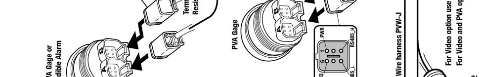
9 PVA Gages
10 NMEA Gages

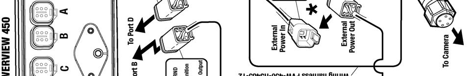
11 Dual Engine Gages NOTE: Port B and C connectors are keyed differently than Port A and D connectors to ensure proper connection
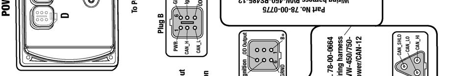
12 USB Wiring

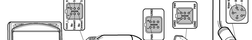
13 Analog Video
14 No Video Wiring

 USB 2.")
 0-5 VDC or 4-20 ma Digital output,")
15 Pin Specifications for Deutsch DT04-6P Style Connections Signal Definitions CAN: 2.0A and 2.0B 1 port isolated according to NMEA 2000 (optional) USB 2.0, Video input (optional): NTSC/PAL, analog input (1) 0-5 VDC or 4-20 ma Digital output, capable of syncing 500mA

16 PV450 Features and Operations Flat Screen Display A color screen displays gauges, soft key commands, and fault messages, as well as menu options for setup and configuration. Soft Key Commands Columns of vertical commands may be located to the left and/or right of the display. They will change according to the options available for the screen being displayed. Soft Keys The soft keys correspond to the soft key commands and allow selections to be made accordingly. MENU Key The bottom left key is a soft key reserved in most cases for the Menu. In rare cases, it could be used for other options. Pressing the MENU key at any time displays the list of menu options. If not labeled, it is the MENU key. ENTER Key The bottom right key is a soft key reserved in most cases for the Enter. In rare cases, it could be used for other options. Pressing the ENTER key will select the option displayed much like the ENTER key on a keyboard. If not labeled, it is the ENTER key


17 Setting Up your PV450 Display for the First Time The guidelines presented below are intended for setting up the PV450 display for the first time. Once the configuration is set up, there is no need to revisit or change any of the settings. NOTE: If you require assistance during the set up process, contact FW Murphy customer support at +1(918) At the main menu, press the soft key to the left of Utilities. 2. The Utilities sub-menu is displayed. 3. From the Utilities sub-menu, select System Settings. The following screen is displayed. 4. With the cursor highlighting the J1939 source addresses, use the left side soft keys to scroll through the ports and the right side soft keys to change the address. Press the
18 Save key to save selected changes or the Restore Defaults key to return to the default settings
19 Product Features Power Up There are two options to connecting the PV450 display: The battery and ignition inputs to display are both connect to the battery The battery input is connected to the battery and the ignition input is connected to the ignition switch. NOTE: If both are connected to the battery, then an inline battery disconnect must be installed. When the ignition is turned on, the PV450 display powers up and the engine health statistics can be viewed via preset gauges. To see more gauge screens, press the Enter key. Main Menu The main menu is activated at any time by pressing the Menu key on the display. The following features are accessed through the main menu: Gauge Display provides a series of screens that display engine and auxiliary information in a variety of formats. Engine Diagnostics displays a list of engine fault codes and descriptions through a DM1 message structure. User Settings allows you to customize the display options for ambient light and brightness, set US or metric units, language, specify the Home screen and screen setup status. Utilities allows configuration of the plug address. Also displays software version information at the top of the page

20 Gauge Display The Gauge Display screen consists of several predefined layouts that contain combinations of analog gauges, straight bar gauges, or digital (text) readouts. These screens are displayed upon startup. To scroll through the various gauge screens, press the Prev and Next soft keys. This can be repeated until all screens have been viewed. The currently displayed screen will stay active until another key is pressed. Soft Key Commands When a Gauge Display screen is active, pressing the Enter key will display soft key commands, as shown below. Continuing to press Enter will toggle through any additional soft keys, and will eventually remove the soft key commands from the screen. Soft Key commands provide quick navigation and access to the following features: Home Prev Day/Night Video (optional) Next Home - This one-touch navigation feature allows a pre-defined Home screen to be accessed from the available Gauge Display screens. Once selected, the Home screen will be displayed anytime the Home key is pressed. NOTE: For instructions on how to setup the Home screen, refer to the User Settings section of this manual

21 Day/Night - Allows you to toggle the display screen between Day View and Night View. NOTE: This feature can also be changed in the User Settings section of this manual. Video When enabled, displays either full screen video or partial video within a window on the gauge display. NOTE: For instructions on how to enable full or partial screen video, refer to the User Settings section of this manual. Full View Video NOTE: For instructions on how to turn screens ON or OFF, refer to the User Settings section of this manual

22 Engine Diagnostics Choosing Engine Diagnostics from the Menu, the display will query the engine(s) ECU and provide feedback on any diagnostic codes that have been activated and stored in the ECU for service needs. The Engine Diagnostics option displays faults based on engine or auxiliary source. The following is a list of field definitions contained on the Engine Diagnostics screen: Device ID identifies the component having the fault; engine 1, 2, or auxiliary. Address identifies the address of the source of the fault (populates the Device ID). Status indicates whether the fault has been corrected. SPN "Suspect Parameter Number" - fault code If not translated into text by the PV450 display, see the engine manufacturer's literature for the definition of the SPN number. FMI Failure Mode Indicator - fault code The FMI is defined by SAE J1939. If not translated into text, see the SAE standard, or the engine manufacturer's literature. Occurrence Count (OC) The number of times the event has been flagged. Description Most common SPN's and FMI's have text for the description stored in the PV450 display. If there is no text, then this SPN and FMI must be defined by referring to the engine manufacturer, or the SAE J1939 standard. Correction Trouble-shooting guidelines for corrective action to take in addressing the fault. NOTE: This field is only used with certain brands and models of engines


23 Fault Code Popups A fault condition will trigger a popup dialog box on the screen describing the nature of the fault. Corresponding red or amber fault lights on the corners of the unit are also activated to indicate the severity of the fault. The following screens are examples of warning and shutdown fault code popups. How to Hide/Show Faults To hide the fault code popup being displayed on the screen, press the soft key on the right next to the Hide icon. The popup will disappear, however the Warning or Stop icon will remain on the screen to indicate there is still a fault. Pressing Hide does not clear the fault; it only hides the popup message. When a fault code has been hidden, a Recall icon will remain on the right side. When this soft key is pressed, the fault code will again be displayed. When a popup message has been activated, a pop-up message will be displayed until the alarm is acknowledged by pressing the Hide key. Scrolling Through Multiple Messages The title-bar of the fault code popup may indicate multiple messages, as in Diagnostic Message 1 of 3. Press the Prev and Next keys to scroll through the different messages
24 User Settings User Settings provides options to specify viewing preferences for the PV450 Display. Pressing yellow Up and Down arrows navigates through the options. To change an option, press the corresponding soft key button next to the desired soft key command. Ambient Light Night and Day options are provided for ambient lighting. The screens below illustrate these options. When the ambient lighting settings are changed in User Settings, the power-on default is changed. NOTE: The ambient lighting option is also accessible through soft key commands on the gauge display screens. When selected, the Day/Night soft key toggles the display to the opposite mode
25 Brightness You can set the brightness control by using the soft keys to change the settings in +5% increments until the desired brightness is achieved. Units NOTE: Brightness level will change with ambient light setting. Two brightness levels are saved; one for day and one for night. Select how units are displayed by using the soft keys to select from the following: USA Standard Metric Bar Metric kpa British Standard

26 Language This option allows you to select the language that will be displayed on the PV450. Available languages include English, French, Spanish, German, Italian, and Chinese. Languages are selected from the soft keys. Press the Down arrow to view additional languages. Additional languages include: Russian, Czech, Japanese, and Brazilian Portuguese. Screen Setup The Screen Setup option provides a list of screens that can be shown when accessing the Gauge Display screens. Press the Up and Down arrow keys on the right to scroll through the screens. Press the Home soft-key to select the screen as home. NOTE: An X in the On/Off checkbox indicates the screen is on. A blank checkbox indicates the screen is turned off
27 The Screen Setup screen also provides the user the ability to turn the screens ON or OFF by pressing the Enable/Disable soft key. If a screen is turned OFF, it will not show up when Gauge Display is activated. Home Screen The Home Screen will be the first screen shown when Gauge Display is selected from the User Setting menu. The Home Screen is set to Engine by default and can be changed using the Screen Setup options on the User Settings screen. Video (Optional) By default, the Video screen is on or Enabled. To Disable video, change Video option to Off in the screen setup dialog box using the Enable/Disable key in the top right corner. An updated image showing video screen highlighted / off will be displayed. Save Once all changes have been made, press Save. The following confirmation screen is displayed


28 Restore Defaults Restore Defaults sets the display to the original factory settings. During troubleshooting, this can be used as a last resort to completely reset the display to a known state. To restore the default user settings, press Restore Defaults. The following confirmation screen is displayed. Utilities Utilities allow you to reset external gauges and configure communication settings. It is typically only accessed when the unit is first installed in order to configure the unit. The following submenu is displayed when Utilities is selected

29 System Settings The System Settings screen displays the current software version loaded on the PV450 display. You can set individual settings for the available options and Save, or choose to select Restore Defaults for the factory settings. The yellow Up and Down keys on the left allow you to move the cursor through J1939 Source Addresses fields. While the cursor is highlighting a field, the gray Up and Down keys scroll through available options. Once all the options have been selected, press Save. Service Reminders This option allows you to reset the 5 built-in service reminders: Change Engine Oil Default interval 50.0 Hrs. Chang Air Filters Default interval 75.0 Hrs. Change Hydraulic Oil Default interval Hrs. Service Engine Default interval Hrs. Service Machine Default interval Hrs. NOTE: The PV450 is Tier 4 compliant. If there are any questions on the Murphy Standard Configuration please contact Murphy technical services at: +1 (918)
30 Specifications Electrical Display Resolution Bonded 4.3 color transmissive TFT LCD WQVGA, 480 x 272 pixels, 16-bit color Aspect Ratio 16:9 Orientation Landscape or portrait Backlighting LED, cd/m2 (30,000 hr lifetime) Microprocessor Freescale imx35, 32bit, 532 MHz Operating System QNX Real Time Flash Memory 256 MB (expandable to 8GB) RAM 128 Mb DDR2 SDRAM Operating Voltage 6-32 VDC, protected against reverse polarity and load-dump Power Consumption 10W Max CAN Two CAN 2.0B; optional NMEA 2000 isolation RS MODBUS Master/Slave Protocols J1939, NMEA 2000, CANopen Connection 4 Deutsch DT 6-pin connectors Keyboard 8 tactile buttons USB USB 2.0 host (full speed), optional OTG support Input (1) Resistive, 0-5 V, or 4-20 ma (software configurable) Video Input (optional) Two NTSC/PAL input channels with one displayed at a time Output (1) open-drain, capable of sinking 500mA With internal rechargeable Li-ion battery; >300 day date/time retention when Real-time Clock not connected to power. Environmental Operating Temperature Storage Temperature Protection Emissions and Immunity Vibration Shock Mechanical Case Material -40º C to +85º C -40º C to +85º C IP 66 and 67, front and back Electromagnetic Compatibility: 2004/108/EC J1113/2, 4, 11, 21, 26 and 41 EN EN (immunity) EN EN Random vibration, 7.86 Grms ( Hz), 3 axis 50G in 3 axis Polycarbonate back case
31 Addendum How to Install a Configuration from a USB Drive For the PV READ ALL INSTRUCTIONS BEFORE CONTINUING! 2. Power OFF the display unit. 3. Insert USB drive with the configuration file into USB port. 4. Press and hold the top left button (continue to hold). 5. Power ON the display while continuing to hold the button a few more seconds then release. 6. Use the keys next to up/down arrows to find the desired file. 7. Use the key next to the right arrow to select and continue. (The right arrow turns green, press again to confirm. Exit by pressing the key next to the red left arrow.) 8. When the installation is complete, a check mark is displayed in the middle of the screen. 9. The unit will reset itself automatically and boot to the new configuration
32 (THIS PAGE INTENTIONALLY LEFT BLANK)
33
34
35
36
37 (THIS PAGE INTENTIONALLY LEFT BLANK)


38
PowerView Model PV450. Installation and Operation Manual Section 78
 PowerView Model PV450 Installation and Operation Manual 00-02-0732 05-19-2011 Section 78 In order to consistently bring you the highest quality, full featured products, we reserve the right to change our
PowerView Model PV450. Installation and Operation Manual Section 78
 PowerView Model PV450 Installation and Operation Manual 00-02-0732 2016-02-26 Section 78 In order to consistently bring you the highest quality, full featured products, we reserve the right to change our
PowerView Model PV750. Installation and Operations Manual Section 78
 PowerView Model PV750 Installation and Operations Manual 00-02-0686 08-20-10 Section 78 In order to consistently bring you the highest quality, full featured products, we reserve the right to change our
HelmView 450 Model HV450. Installation Manual Section 78
 HelmView 450 Model HV450 Installation Manual 00-02-0727 2015-04-16 Section 78 In order to consistently bring you the highest quality, full-featured products, we reserve the right to change our specifications
HelmView 450 Model HV450. Operation Manual Section 78
 HelmView 450 Model HV450 Operation Manual 00-02-0870 2015-04-16 Section 78 In order to consistently bring you the highest quality, full-featured products, we reserve the right to change our specifications
PowerView Model PV780. Operations Manual Section 78
 PowerView Model PV780 Operations Manual 00-02-0859 2013-03-19 Section 78 In order to consistently bring you the highest quality, full featured products, we reserve the right to change our specifications
PowerView Model PV485. Installation Manual Section 78
 PowerView Model PV485 Installation Manual 00-02-1018 2017-05-23 Section 78 In order to consistently bring you the highest quality, full-featured products, we reserve the right to change our specifications
HelmView Model HV750. Installation Manual Section 78
 HelmView Model HV750 Installation Manual 00-02-0803 11-11-11 Section 78 In order to consistently bring you the highest quality, full featured products, we reserve the right to change our specifications
HelmView Model HV750; HVS750. Installation Manual Section 78
 HelmView Model HV750; HVS750 Installation Manual 00-02-0803 2013-05-20 Section 78 In order to consistently bring you the highest quality, full featured products, we reserve the right to change our specifications
HelmView Model HVS780. Operations Manual Section 78
 HelmView Model HVS780 Operations Manual 00-02-0883 2013-02-20 Section 78 In order to consistently bring you the highest quality, full featured products, we reserve the right to change our specifications
HelmView Model HV750; Model HVS750. Operations Manual Section 78
 HelmView Model HV750; Model HVS750 Operations Manual 00-02-0805 03-07-12 Section 78 In order to consistently bring you the highest quality, full featured products, we reserve the right to change our specifications
PowerView Model PV1000. Hardware Installation Manual Section 78
 PowerView Model PV1000 Hardware Installation Manual 00-02-0599 07-19-07 Section 78 In order to consistently bring you the highest quality, full featured products, we reserve the right to change our specifications
PowerView Model PV350 and PV380. Installation Manual Section 78
 PowerView Model PV350 and PV380 Installation Manual 00-02-0880 2013-05-17 Section 78 In order to consistently bring you the highest quality, full featured products, we reserve the right to change our specifications
PowerView TM Model PV350 and PV380. Operations Manual Section 78
 PowerView TM Model PV350 and PV380 Operations Manual 00-02-0879 2012-11-30 Section 78 In order to consistently bring you the highest quality, full featured products, we reserve the right to change our
*Approved by CSA for non-hazardous locations (Group Safety Publication IEC Third Edition).
.") PowerCore Model MPC-20 Installation Manual *Approved by CSA for non-hazardous locations (Group Safety Publication IEC 61010-1 Third Edition). Products covered in this document comply with European Council
PowerCore Model MPC-20 Installation Manual *Approved by CSA for non-hazardous locations (Group Safety Publication IEC 61010-1 Third Edition). Products covered in this document comply with European Council
HelmView Model HV1000. Operations Manual Section 78
 HelmView Model HV1000 Operations Manual 00-02-0604 08-08-07 Section 78 In order to consistently bring you the highest quality, full featured products, we reserve the right to change our specifications
PowerView. Model PV-101 User s Guide. Rev Catalog Section 78
 PowerView Model PV-101 User s Guide Rev 09-10-08 00-02-0605 Catalog Section 78 In order to consistently bring you the highest quality, full featured products, we reserve the right to change our specifications
PowerCore Model TEC-10 Installation Manual
 PowerCore Model TEC-10 Installation Manual Products covered in this document comply with European Council electromagnetic compatibility directive 2014/30/EU and electrical safety directive 2014/35/EU.
PowerView. Model PV-101-A, V2.3 User s Guide Section 78
 PowerView Model PV-101-A, V2.3 User s Guide 10-18-11 00-02-0795 Section 78 In order to consistently bring you the highest quality, full featured products, we reserve the right to change our specifications
MLC 380 R2. For Mechanical Engines. Installation Manual
 MLC 380 R2 For Mechanical Engines Installation Manual In order to consistently bring you the highest quality, full featured products, we reserve the right to change our specifications and designs at any
PowerView. Model PV-101-C User s Guide Version Catalog Section 78
 PowerView Model PV-101-C User s Guide Version 3.1 10-11-10 00-02-0718 Catalog Section 78 Table of Contents Introduction... 1 Engine and Transmission Parameters 2 Faceplate Features 3 Navigation and Keypad
PowerView PV380-R2 Murphy Standard Configuration
 2016-06-15 00-02-0997 Section 78 PowerView PV380-R2 Murphy Standard Configuration Operations Manual *Products covered in this document comply with European Council electromagnetic compatibility directive
Programmed with Eaton Pro-FX Control Software 32-bit Processor, 4.3 WVQA Sunlight Viewable Display
 VFX40m Electronic Programmable Display Programmed with Eaton Pro-FX Control Software 32-bit Processor, 4.3 WVQA Sunlight Viewable Display The high performance VFX40m display is designed to provide an operator
Programmed with Eaton Pro-FX Control Software 32-bit Processor, 4.3 WVQA Sunlight Viewable Display
 VFX40m Electronic Programmable Display (Part Number: 102EC30400A) Programmed with Eaton Pro-FX Control Software 32-bit Processor, 4.3 WVQA Sunlight Viewable Display The high performance VFX40m display
Programmed with Eaton Pro-FX Control Software 32-bit Processor, 4.3 WVQA Sunlight Viewable Display
 VFX41m Electronic Programmable Display Programmed with Eaton Pro-FX Control Software 32-bit Processor, 4.3 WVQA Sunlight Viewable Display The high performance VFX41m display is designed to provide an operator
TECHNICAL DATASHEET #TDAX050000K CAN
 This cost-effective, compact and robust CAN display shows machine, engine and transmission operating parameters and service codes. Enhanced operating information made available to a vehicle operator improves
Features: Contents: If you are missing any of the above components please contact Racepak at
 -------------------------------------------------------------------------------------------- 250-DS-UDX -------------------------------------------------------------------------------------------- Features:
Programmed with Eaton Pro-FX Control Software 32-bit Processor, 7 WVQA Sunlight Viewable Display
 VFX70m Electronic Programmable Display Programmed with Eaton Pro-FX Control Software 32-bit Processor, 7 WVQA Sunlight Viewable Display The high performance VFX70m display is designed to provide an operator
PV101-C Configuration Software V3.2. Installation and Operations Manual Section 78
 PV101-C Configuration Software V3.2 Installation and Operations Manual 00-02-0797 08-18-11 Section 78 In order to consistently bring you the highest quality, full featured products, we reserve the right
ODES Zeus Touch Owner s Manual
 ODES Zeus Touch 2017 Owner s Manual 2016-09-15 1611997 We continually strive to bring you the highest quality, full-featured products. As a result, you may find that your actual display screens may be
User Manual. cmt-iv5 Startup Guide
 User Manual cmt-iv5 Startup Guide v 2.2 JAN 8, 2016 Table of Contents Chapter1. Overview... 1 1.1. Specification... 1 1.2. Dimensions... 2 1.3. Ethernet port... 3 1.4. CR1225 battery... 3 1.5. Power connection...
A Axis M-Functions Level 1 A Axis Standard A Axis SMT Level 2. Each console includes the following:
 Hardware List The 3000M Crusader II Upgrade system has been custom configured to provide the necessary hardware required for installation on your machine. Verify that you have received all the correct
Technical Data Sheet OPUS A3 STANDARD Basic
 Technical Data Sheet OPUS A3 STANDARD Basic 17.01.2018 Errors and technical changes excepted 1 Notes and Warnings Attention! This description is not a substitution for the concerned product s documentation.
DSEM870. DSEControl PROGRAMMABLE DISPLAY FOR USE IN VEHICLES AND OFF-HIGHWAY MACHINERY
 PROGRAMMABLE DISPLAY FOR USE IN VEHICLES AND OFF-HIGHWAY MACHINERY OVERVIEW DC SUPPLY 8 V DC to 32 V DC CURRENT CONSUMPTION OPERATING CURRENT < 1000 ma at 12 V and 24 V without external loads < 1500 ma
Moomba Boats PV480 Color Display
 Moomba Boats PV480 Color Display 2018 Owner s Manual 1715055 2017-08-30 We continually strive to bring you the highest quality, full-featured products. As a result, you may find that your actual display
Analog Flat Panel Monitor
 Analog Flat Panel Monitor Regular and High Brightness Installation and Operations Manual For use with models: LM9001 LM8001 LM6001 LM9006 LM8006 LM6006 LS9001 LS8001 LS6001 LS9006 LS8006 LS6006 DOC-IWS-641
P/N: AX Distribute your control functions directly onto the valve.
 TECHNICAL DATASHEET #TDAX022311 Dual Plug-In Valve Controller, CANopen 2-2.5A Outputs Programmable Distribute your control functions directly onto the valve. P/N: AX022311 Features: Configurable for 1
Control Panel CP600-eCo CP604, CP604-B
 DATA SHEET Control Panel CP600-eCo CP604, CP604-B 1 Ordering Data Part No. Description Product Life Cycle Phase 1SAP504100R0001 CP604, control panel, TFT graphical display, single-touch screen, 4.3, Active
Technical Data Sheet OPUS A3 STANDARD Basic TDS OPUS A3sB,
 Technical Data Sheet OPUS A3 STANDARD Basic TDS OPUS A3sB, 26.08.2013 OPUS A3 Standard Basic Landscape OPUS A3 Standard Basic Landscape/Portrait 1 Order Numbers OPUS A3 STANDARD Basic Wachendorff Projektor
HMIPWC7D0E01 Panel PC Optimum - Compact Flash - 15'' - DC - Fanless
 Characteristics Panel PC Optimum - Compact Flash - 15'' - DC - Fanless Main Range of product Product or component type Terminal type Apr 04, 2018 Magelis ipc PC panel Touchscreen display Processor name
Warning! It will cause malfunction if the monitor is operating with unspecified power supply adaptor or incorrect power voltage. Do not expose this
 User Manual / Installation Guide Model No. P150VR/P150VG Warning! It will cause malfunction if the monitor is operating with unspecified power supply adaptor or incorrect power voltage. Do not expose this
CONCEPT P/N: AX Concept TECHNICAL DATASHEET #TDAX Analog Input CAN Controller CAN (SAE J1939 or CANopen ) with Electronic Assistant
 with Electronic Assistant") Concept TECHNICAL DATASHEET #TDAX030400 6 Analog Input CAN Controller CAN (SAE J1939 or CANopen ) with Electronic Assistant Features: 6 analog inputs (0-5V, 0-10V, 0-20mA, 4-20mA, Resistance, PWM, Digital,
Concept TECHNICAL DATASHEET #TDAX030400 6 Analog Input CAN Controller CAN (SAE J1939 or CANopen ) with Electronic Assistant Features: 6 analog inputs (0-5V, 0-10V, 0-20mA, 4-20mA, Resistance, PWM, Digital,
FG-3000R Digital Force Gauge Operation Manual
 FG-3000R Digital Force Gauge Operation Manual Operators should wear protection such as a mask and gloves in case pieces or components break away from the unit under test. Whether the unit is ON or OFF,
MultiViu Flex 4 Data Sheet
 Division Interior MultiViu Flex 4 Data Sheet Description CAN-capable multifunction Solution Features: Robust and versatile design CAN-capability (SAE J1939, CANopen) Video interface Analogue and digital
Installation and Operations Manual
 00-02-0528 Revised 02/06 Section 78 Installation and Operations Manual Please read the following information before installing. A visual inspection of this product for damage during shipping is recommended
User Manual. cmt-iv5 Startup Guide
 User Manual cmt-iv5 Startup Guide Table of Contents Chapter1. Overview... 1 1.1. Specification... 1 1.2. Dimensions... 2 1.3. Ethernet port... 3 1.4. CR1225 battery... 3 1.5. Power connection... 3 1.6.
FG-3000 Digital Force Gauge Operation Manual
 FG-3000 Digital Force Gauge Operation Manual Operators should wear protection such as a mask and gloves in case pieces or components break away from the unit under test. Whether the unit is ON or OFF,
Absolute Encoders Multiturn
 The multiturn encoders 6 and 8, with interface and combined optical and magnetic sensor technology, offer a maximum resolution of 5 bits. These encoders are programmable via the Ezturn software. The hollow
Control Panel CP600 CP651, CP651-WEB
 DATA SHEET Control Panel CP600 CP651, CP651-WEB 1 Ordering Data Part No. Description Product Life Cycle Phase 1SAP551100R0001 CP651, control panel, TFT graphical display, single-touch screen, 10.4, Active
COMPACT FLEXIBLE ALL IN ONE INDUSTRIAL PUMP CONTROL ELECTRONIC MONITORING SYSTEM CONTROLLER
 COMPACT FLEXIBLE ALL IN ONE INDUSTRIAL PUMP CONTROL ELECTRONIC MONITORING SYSTEM CONTROLLER ONE EASY-TO-USE CONTROL. MANY APPLICATIONS. The EMS PRO is a rugged, all-in-one industrial controller designed
S7999D SOLA Operator Interface Display
 S7999D Operator Interface Display INSTALLATION INSTRUCTIONS APPLICATION The S7999D is microprocessor-based color touch-screen Operator Interface (OI) display that provides an operator interface for monitoring
Vertiv Local Rack Access 18.5" LED LCD Console
 Vertiv Local Rack Access 18.5" LED LCD Console With Integrated Keyboard, Touchpad and Dual USB 2.0 Ports Installer/User Guide Technical Support Site If you encounter any installation or operational issues
PowerView Model PV101-A, V2.3 Modifications
 PowerView Model PV101-A, V2.3 Modifications The following changes have been made to PowerView 101-A, please read this and keep with the User s Guide. Utilities Menu Information in Software Version and
Cascade Configuration Tool
 Cascade Configuration Tool Version 1.0.10 Installation and Operations Manual 00-02-0724 01-25-11 Section 40 In order to consistently bring you the highest quality, full featured products, we reserve the
Control Panel CP600 CP635-FB, CP635-FW
 DATA SHEET Control Panel CP600 CP635-FB, CP635-FW 1 Ordering Data Part No. Description Product Life Cycle Phase 1SAP535110R6001 CP635-FB, control panel, TFT graphical display, single-touch projected Active
3700 SERIES USER MANUAL
 SAFETY GUIDE This manual contains the precautions necessary to ensure your personal safety as well as for protection for the products and the connected equipment. These precautions are highlighted with
Control Panel CP600 CP635, CP635-B, CP635-WEB
 DATA SHEET Control Panel CP600 CP635, CP635-B, CP635-WEB 1 Ordering Data Part No. Description Product Life Cycle Phase 1SAP535100R0001 CP635, control panel, TFT graphical display, single-touch screen,
Applications: Stationary, portable power generator sets Genset control systems
 Technical Datasheet #TDAXRTD8 RTD Scanner 8 RTD Channels CAN, SAE J1939 with Electronic Assistant P/N: AXRTD8 Description: The RTD Scanner monitors 8 RTD inputs from a diesel engine and the temperature
ABM International, Inc. Lightning Stitch Checklist 9/13/2013
 ABM International, Inc. Lightning Stitch Checklist 9/13/2013 1) Piggy backed board assembly (1) Piggy back board assembly tested? Yes No 24v passed XB passed XA passed YB passed YA passed SAFE passed S/S
CF3000 Dealer Diagnostic Tool Instruction Manual
 CF3000 Dealer Diagnostic Tool Instruction Manual Table of Contents: About the CF3000......3 Important Precautions......4 Components....5 Charging the CF3000......7 Licensing the CF3000.......8 Updating
Table of Contents pg " Display pg Cruise Mode pg Map Screen pg Stereo Screen pg Depth Screen pg.
 USER GUIDE TABLE OF CONTENTS Table of Contents pg. 2 12.3" Display pg. 3-4 Cruise Mode pg. 5-6 Map Screen pg. 6-13 Stereo Screen pg. 14-17 Depth Screen pg. 17 Settings Screen pg. 18-24 Media Screen pg.
HG series Hand grip Hall effect joysticks
 Distinctive features and specifications Rugged, hand operation Hall effect sensing Sealed up to IP68 1 million life cycles Redundant outputs available Analog, USB and custom outputs CANbus J1939 and CANopen
HG series Hand grip Hall effect joysticks
 Distinctive features and specifications Rugged, hand operation Hall effect sensing Sealed up to IP68 1 million life cycles Redundant outputs available Analog, USB and custom outputs CANbus J1939 and CANopen
Technical Data Sheet OPUS A3 STANDARD Basic TDS OPUS A3sB,
 Technical Data Sheet OPUS A3 STANDARD Basic TDS OPUS A3sB, 03.09.2012 OPUS A3 Standard Basic Landscape OPUS A3 Standard Basic Landscape/Portrait 1 Order Numbers OPUS A3 STANDARD Basic Wachendorff Projektor
BEP 600-ACSM AC SYSTEMS MONITOR. Installation and Operating Instructions. Page 1
 BEP 600-ACSM AC SYSTEMS MONITOR Installation and Operating Instructions Page 1 This page has been deliberately left blank Page 2 Table of Contents 1. BASICS 4 WARNING AND CAUTION 4 WARNING 4 CAUTION 4
M2 OLED Temperature Monitor Instructions PN 1841
 M2 OLED Temperature Monitor Instructions PN 1841 Installation Checklist Check for components included Read Warning and Cautions Read page 3 for mounting instructions Read System Overview, Mounting Considerations,
LevelOne. KVM-0115/KVM / 17-inch LCD KVM Rack Console. User Manual. Version
 LevelOne KVM-0115/KVM-0117 15 / 17-inch LCD KVM Rack Console User Manual Version 1.0-1305 1 SAFETY INSTRUCTIONS 1. Please read these safety instructions carefully. 2. Please keep this User Manual for later
MULTI-FUNCTION DISPLAYS A3416: 8 INCH / A3417: 13.3 INCH
 Multi-Function Displays (A3416 & A3417) - Overview, Configuration MULTI-FUNCTION DISPLAYS A3416: 8 INCH / A3417: 13.3 INCH The OctoPlex A3416/A3417, Multi-Function Displays allow for the users to control
1.6. Counters, Panel Meters, Tachometers and Timers. Contents Description Fusion Integrated Machine Control Standards and Certifications...
 .6 Contents Standards and Certifications............... Product Selection....................... Technical Data and Specifications........... Dimensions............................ Learn Online Page V3-T-04
DVR 514 Digital Video Recorder
 DVR 514 Digital Video Recorder User Manual 2010 Sakar International, Inc. All rights reserved. Windows and the Windows logo are registered trademarks of Microsoft Corporation. All other trademarks are
EMS467 Monitoring System. Installation and Operations Manual Section 40
 EMS467 Monitoring System Installation and Operations Manual 00-02-0672 01-26-10 Section 40 In order to consistently bring you the highest quality, full featured products, we reserve the right to change
-Direct.com FG-3000 Digital Force Gauge Operation Manual
 FG-3000 Digital Force Gauge Operation Manual Operators should wear protection such as a mask and gloves in case pieces or components break away from the unit under test. Whether the unit is ON or OFF,
TCNM-ACBB1 Installation Manual
 The TCNM-ACBB1 is a connection box that can be used as an accessory to facilitate system connections for installation and device replacement of several Banner family reading devices. System cabling is
Pronto. User Guide. User Guide
 Pronto EN 1 Pronto Copyright 2005 Royal Philips Electronics, Interleuvenlaan 72-74, 3000 Leuven (Belgium) Remark: All rights are reserved. Reproduction in whole or in part is prohibited without prior consent
TECHNICAL PRODUCT DATASHEET
 FORM-ENG-0018 REV A 06-02-03 ISO 9001 CERTIFIED Phone: (352) 629-5020 or 800-533-3569 Fax: (352)-629-2902 SUITABLE FOR EXTERNAL DISTRIBUTION TECHNICAL PRODUCT DATASHEET ES-Key Climate Control Module P/N
Technical Data Sheet OPUS A3 ECO Full
 Technical Data Sheet OPUS A3 ECO Full 17.01.2018 Errors and technical changes excepted 1 Notes and Warnings Attention! This description is not a substitution for the concerned product s documentation.
615HD Digital Video Camera
 615HD Digital Video Camera User Manual 2009-2011 Sakar International, Inc. All rights reserved. Windows and the Windows logo are registered trademarks of Microsoft Corporation. All other trademarks are
PWS500S Installation Guide
 PWS500S Installation Guide F-1 Introduction The PWS500 is equipped with a 3.0" sized (160Hx80V) flat panel display and analog resistive touch screen. The IP 65 (NEMA 4) rated front panel seal and INDUSTRIAL
DM-170/SRM-170/SRM-170A. User Manual. Version 3.2
 DM-170/SRM-170/SRM-170A User Manual Version 3.2 May 8, 2003 Copyright Notice Copyright 2003 by ICP Electronics Inc. All Rights Reserved. The information in this document is subjected to change without
What s in the Box? REAR VIEW SAFETY
 TM 1 What s in the Box? 1 Full HD Color Infra-red Weather Proof Camera 1 Full HD 7" TFT LCD Color Monitor w/monitor Mount 1 Power Harness 1 66 Camera Cable 1 Power Connection Wire 1 Screw Kit for installation
Quick Start Guide and Health and Safety Information
 D397-10-880 Issue F Original Quick Start Guide and Health and Safety Information Turbo Instrument Controller (TIC) Description TIC Instrument Controller 3 Gauge TIC Instrument Controller 6 Gauge TIC Instrument
Technical Data Sheet OPUS A3 STANDARD Full
 Technical Data Sheet OPUS A3 STANDARD Full TDS OPUS A3sF, 20.02.2015 OPUS A3 Standard Full 1 Order Numbers OPUS A3 STANDARD Full Wachendorff Elektronik Wachendorff Projektor Landscape Landscape/Portrait
P/N: AX Applications: power gen set engine control systems oil and gas equipment automation off-highway machine automation
 TECHNICAL DATASHEET #TDAX031200 11:9 CAN CONTROLLER 11 Inputs (Analog, Digital, Magnetic Pick Up, Universal Signal) 4 Relay, 4 Analog, 1 Valve Driver Outputs 2 CAN (SAE J1939) with Electronic Assistant
SHIMPO INSTRUMENTS. FG-7000T Digital Torque Gauge Operation Manual
 FG-7000T Digital Torque Gauge Operation Manual SHIMPO INSTRUMENTS Operators should wear protection such as a mask and gloves in case pieces or components break away from the unit under test. Whether the
Nexio. NEXIO Co.,Ltd. NIO150SA Desktop Touch Monitor. LCD Monitor User Guide.
 Nexio NEXIO Co.,Ltd. www.inexio.co.kr NIO150SA Desktop Touch Monitor VGA, DVI, Composite, S-video & Audio supported LCD Monitor User Guide Please see the following page for the latest enhancements. Revised
TTC Series Torque Tool Tester Operation Manual
 TTC Series Torque Tool Tester Operation Manual Operators should wear protection such as a mask and gloves in case pieces or components break away from the unit under test. Whether the unit is ON or OFF,
ETM MD100 Drive System 1/2HP (370W) User Manual. Table of Contents. Drive Features
 User Manual. Table of Contents. Drive Features") Table of Contents Drive Features... 1 Drive Specifications... 2 Certifications... 3 Installation - Drive Dimensions... 3 Motor Dimensions (mm)... 4 Drive Mounting... 4 Wiring... 5 I/O Terminals... 9 Menu...
Table of Contents Drive Features... 1 Drive Specifications... 2 Certifications... 3 Installation - Drive Dimensions... 3 Motor Dimensions (mm)... 4 Drive Mounting... 4 Wiring... 5 I/O Terminals... 9 Menu...
DATA SHEET Advanced Graphical Interface, AGI 100 series
 DATA SHEET Advanced Graphical Interface, AGI 100 series Graphic overview and touch screen control Compatible with DEIF controllers Easy programming Create macro commands Multi-language support IP65 protected
TECHNICAL DATASHEET #TDAX Analog Signal Output CAN Controller (SAE J1939)
") Distributed I/O for Engine Control Systems Features: 1 analog signal output (voltage or current) User selectable output range from +/-10V or +/-20 ma, including: 0-5V; 0-10V; +/-5V; +/-10V; 0-20mA; and
Distributed I/O for Engine Control Systems Features: 1 analog signal output (voltage or current) User selectable output range from +/-10V or +/-20 ma, including: 0-5V; 0-10V; +/-5V; +/-10V; 0-20mA; and
99 Washington Street Melrose, MA Phone Toll Free Visit us at
 99 Washington Street Melrose, MA 02176 Phone 781-665-1400 Toll Free 1-800-517-8431 Visit us at www.testequipmentdepot.com Table of Contents 1. General Safety Requirements... 1 2. Safety Terms and Symbols...
EXPRESS SETUP. PanelMate 1700 Series PanelMate Power Pro. Cutler-Hammer
 EXPRESS SETUP PanelMate 1700 Series PanelMate Power Pro Cutler-Hammer Installation Unpacking Carefully remove all equipment from the packing cartons and inspect all parts for damage in shipment. Check
User Manual LKS-CD17DR LKS-CD19DR. 17 LCD Dual Rail Console Drawer with Modular KVM Switch. 19 LCD Dual Rail Console Drawer with Modular KVM Switch
 User Manual LKS-CD17DR 17 LCD Dual Rail Console Drawer with Modular KVM Switch LKS-CD19DR 19 LCD Dual Rail Console Drawer with Modular KVM Switch Rev 2.0 Packing List The complete LKS-CD17DR / CD19DR dual
DPL4000 Portable Low Range Dew Point Analyzer
 OPERATIONS MANUAL DPL4000 Portable Low Range Dew Point Analyzer 7205 Edington Drive / Cincinnati, OH 45249 / Tel (513) 772-0060 / Fax (513) 772-9466 Page #1 of 16 M4581 DPL4000 Product Description: This
PanelView Plus/VersaView CE Terminals and Display Modules
 Installation Instructions PanelView Plus/VersaView CE Terminals and Display Modules (Catalog Numbers 2711P-xxxxxx, 6182H-xxxxxx) English Inside: Overview...2 For More Information...2 Modular Components...3
LevelOne KVM User Manual. 17 Modularized KVM Console V
 LevelOne KVM-0217 17 Modularized KVM Console User Manual V1.0.0-0708 SAFETY INSTRUCTIONS 1. Please read these safety instructions carefully. 2. Please keep this User Manual for later reference. 3. Please
Junos WebApp Secure 5.0 Hardware Guide
 Junos WebApp Secure 5.0 Hardware Guide Junos WebApp Secure 5.0 Hardware Guide This document contains a specification for the MWS1000 hardware appliance, as well as instructions for installation into a
Instruction and Operations Manual
 1 GARTECH Enterprises, Inc. Rev 2 01-23-09 Instruction and Operations Manual Portable Test Cell Overview The primary purpose of the Portable Test Cell is to allow the user the ability to control the engine
KS 108 easy Compact automation unit for industrial control and process technology
 PMA KS 108 easy Compact automation unit for industrial control and process technology Combines control, sequencing, and operation Comprehensive function library with integrated operator dialogs BlueDesign
Technical Data Sheet OPUS A6 ECO Basic TDS OPUS A6eB,
 Technical Data Sheet OPUS A6 ECO Basic TDS OPUS A6eB, 26.08.2013 OPUS A6 ECO Basic Landscape 1 Order Numbers OPUS A6 ECO Basic Wachendorff Projektor Landscape Landscape with touch CoDeSys Landscape Landscape
Lightning Stitch Assembly
 ABM International, Inc. 1 1.0: Parts List Lightning stitch motor and drive assembly (Qty. 1) Lightning stitch piggy backed controller board assembly (Qty. 1) Touchscreen (Qty. 1) 2 9-pin Serial cable (Qty.