Equipment Support Structures
|
|
|
- Jade Washington
- 5 years ago
- Views:
Transcription
1 Equipment Support Structures Overview Conventions What's New? Getting Started Setting Up Your Session Creating a Simple Structural Frame Creating Non-uniform Columns Creating Plates with Openings Bracing the Foundation Generating a BOM User Tasks Creating a Foundation Document Creating a Grid Creating Support Structures Making Up a List of Sections Creating Members Creating Infills Creating Members on Supports Creating Plates Creating End Plates Modifying, Joining & Moving Modifying Members Modifying Plates Joining Structures Splitting Structures Translating Components Rotating Components Manipulating Components Exporting Wireframe Skeletons Generating BOMs Equipment Support Structure Package in Knowledge Expert Managing User Sections Sketching Profiles for User Sections Defining Anchor Points for User Sections Creating & Completing Parametric Section Catalogs Interoperability with CATIA V5 Producing Drawings using the Options Dialog Box Producing Drawings Using Generative View Styles
2 Creating Cutouts Creating Flanges Creating Assembly Constraints Working with ENOVIA LCA: Optimal CATIA PLM Usability Workbench Description Design Toolbar Assembly Toolbar Specification Tree Customizing Equipment Support Structures Structure Drawing Managing Structure Settings via a VB Macro Glossary Index
3 Overview Welcome to the Equipment Support Structures User's Guide. This guide is intended for users who need to become quickly familiar with the Equipment Support Structures Version 5 product. This overview provides the following information: Equipment Support Structures in a nutshell Before reading this guide Getting the most out of this guide Accessing sample documents Conventions used in this guide Equipment Support Structures in a Nutshell Version 5 Equipment Support Structures allows you to model equipment supports, including foundations, for all disciplines. It offers an easy-to-use and easy-to-learn graphic interface that lets you design equipment supports in context and take advantage of full associativity when creating and modifying supports. Small equipment supports are sized by design rules with often used supports taken from catalogs. Equipment supports are made of plate parts and profile parts. This product addresses preliminary and detailed design requirements for equipment supports, machinery packages, gratings, and other miscellaneous supports including light legs and hangers of distributed systems, headers for small equipment as well as other small foundations. As a scalable product, Equipment Support Structures can be used with other Version 5 products such as Part Design, Assembly Design, Sheetmetal Design, and Generative Drafting. Before Reading this Guide
4 Before reading this guide, you should be familiar with basic Version 5 concepts such as document windows, standard and view toolbars. We therefore recommend that you read the Infrastructure User's Guide that describes generic capabilities common to all Version 5 products. You may also like to read the following complementary product guides, for which the appropriate license is required: Part Design User's Guide Assembly Design User's Guide Sheetmetal Design User's Guide Generative Drafting User's Guide. For information on VB macro capabilities, refer to the Automation Documentation. Getting the Most Out of this Guide To get the most out of this guide, we suggest you start reading and performing the step-by-step tutorial Getting Started. This tutorial will let you get you acquainted with the product. Once you have finished, you should move on to the User Task section of this guide. This steps you through basic procedures and includes useful tips for getting the most out of the product. The Workbench Description, which describes the Equipment Support Structures-dedicated toolbar, and the Customizing section, which explains how to customize your personal environment, will also certainly prove useful. Navigating in the Split View mode is recommended. This mode offers a framed layout allowing direct access from the table of contents to the information. Accessing Sample Documents To perform some scenarios, you will be using sample documents contained in the online/essug/samples folder. Where samples are provided for capabilities common to different products, these samples will be found in the online/cfysm/samples folder. For more information about this, refer to Accessing Sample Documents in the Infrastructure User's Guide.
5 Conventions Certain conventions are used in CATIA, ENOVIA & DELMIA documentation to help you recognize and understand important concepts and specifications. Graphic Conventions The three categories of graphic conventions used are as follows: Graphic conventions structuring the tasks Graphic conventions indicating the configuration required Graphic conventions used in the table of contents Graphic Conventions Structuring the Tasks Graphic conventions structuring the tasks are denoted as follows: This icon... Identifies... estimated time to accomplish a task a target of a task the prerequisites the start of the scenario a tip a warning information basic concepts methodology reference information information regarding settings, customization, etc. the end of a task
6 functionalities that are new or enhanced with this release allows you to switch back to the full-window viewing mode Graphic Conventions Indicating the Configuration Required Graphic conventions indicating the configuration required are denoted as follows: This icon... Indicates functions that are... specific to the P1 configuration specific to the P2 configuration specific to the P3 configuration Graphic Conventions Used in the Table of Contents Graphic conventions used in the table of contents are denoted as follows: This icon... Gives access to... Site Map Split View mode What's New? Overview Getting Started Basic Tasks User Tasks or the Advanced Tasks Workbench Description Customizing Reference Methodology Glossary
7 Index Text Conventions The following text conventions are used: The titles of CATIA, ENOVIA and DELMIA documents appear in this manner throughout the text. File -> New identifies the commands to be used. Enhancements are identified by a blue-colored background on the text. How to Use the Mouse The use of the mouse differs according to the type of action you need to perform. Use this mouse button... Whenever you read... Select (menus, commands, geometry in graphics area,...) Click (icons, dialog box buttons, tabs, selection of a location in the document window,...) Double-click Shift-click Ctrl-click Check (check boxes) Drag Drag and drop (icons onto objects, objects onto objects) Drag Move Right-click (to select contextual menu)
8 Customizing Settings What's New? Better management of settings You can now manage structure settings via a VB macro

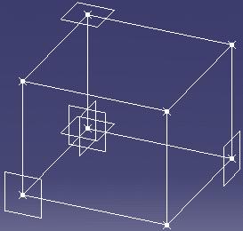
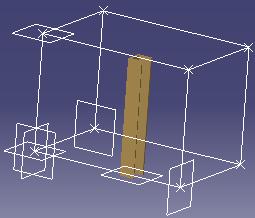
9 Getting Started This tutorial will guide you step-by-step through your first Equipment Support Structures session, allowing you to get acquainted with the product. You will need a Version 5 session and should be familiar with basic concepts such as document windows, standard and view toolbars. You should be able to complete this tutorial in about 15 minutes. The resulting foundation which consists of a braced-frame of beams and columns should look like this:
10 Setting Up Your Session Creating a Simple Structural Frame Creating Non-uniform Columns Creating Plates with Openings Bracing the Foundation Generating a BOM
11 Setting Up Your Session This first task shows you how to enter the Equipment Support Structures workbench and set up your Version 5 session. In this task, you will: Manage associativity Customize settings Typify your document as a a foundation document Create a grid defining the overall dimensions of your foundation. 1. Select Equipments & Systems -> Equipment Support Structures from the Start menu. The Equipment Support Structures workbench is displayed. 2. Switch to Design Mode (Edit -> Representations). Associativity To ensure associativity between the structures you are going to create and the grid used as a construction aid, set the following options. 3. Select Tools -> Options from the menu bar. 4. Click Infrastructure -> Part Infrastructure in the left-hand box of the Options dialog box, then select the General tab. 5. Check Keep link with selected object and Synchronize all external references for update. Equipment Support Structures Settings You will now customize structure materials and specify paths giving you access to the sections you will use to create your foundation. 6. Click Equipments & Systems -> Equipment Support Structures in the left-hand box of the Options dialog box then select the Equipment Support Structures tab. 7. Set member and plate material to Steel. 8. To access available sections: Create a user folder to contain these sections, naming it Section for example Enter e:\section in the Directory field under Section storage to identify the path to this folder. 9. Ensure that the path to the folder containing sample standard catalog sections in the Directory field under Catalogs storage is correctly set: install_folder/startup/components/structuralcatalogs For more information on the install folder, see the Infrastructure User's Guide. 10. Click OK in the Options dialog box when done.
12 Creating a Foundation Document You must first typify your document as a foundation document. 11. Click the Foundation icon: The Foundation Definition dialog box appears. 12. Identify your foundation document. 13. Click OK when done. The document is characterized as a foundation document. Creating a Grid 14. You will create a simple 3D grid defining the overall dimensions of your foundation. Click the Grid icon. The Grid Definition dialog box appears.
 as well as the number of points along x, y and z axes, 1 in each case.")
13 15. Enter a name for the grid you want to create in the Name box: The grid will be identified by this name in the specification tree. 16. Specify Cartesian grid coordinates: Enter the distance between grid points in Spacing boxes (1000 x 1000 x 750 mm respectively) as well as the number of points along x, y and z axes, 1 in each case. 17. Click OK to create the grid. The grid is created and is identified in the specification tree.
14
15 Creating a Simple Structural Frame This task shows you how to create and place the four beams and two of the four columns making up the structural frame of your foundation. But first, you will load the section you will use throughout the scenario. 1. Double-click the Member on Support icon. The Member on Support dialog box appears. Note that the Section field is blank: this is because there are as yet no available sections. You will load equal angle shape L3x3x0.25 from the AISC catalog. This is the shape that you will use for members throughout this scenario. 2. In the Section list, select Other section... The Catalog Browser dialog box is displayed. The current catalog is the correct catalog. Browse the list of families and double-click Equal_Angles (equal leg angle shapes): All the shapes in this family are listed.


16 Browse the listed shapes, then click L3x3x0.25 to preview it. Click OK. The Section list in the Member on Support dialog box is updated.

17 3. Set Type to Beam. 4. Set the anchor point, anchoring the section along the support axis, to Bottom left. 5. Define the member support: select one of the grid lines. Note: You are using the grid to assist you create your foundation. A preview guides you. Notice that the section is not correctly oriented around its anchor point.


18 6. Set Orientation to 270 degrees, then click OK in the dialog box to create the member. The dialog box appears again, ready for you to create the other beams. 7. Create the other three beams in the same way, taking care to orient them properly.

19 You are now ready to create the two straight columns. 8. Change the Type to Column and set the Anchor point to Bottom right, then select one of the vertical support lines. First column characteristics: Anchor point: Bottom right Orientation: 180 degrees Do not forget to check section orientation before clicking OK! Right-clicking the member in the specification tree gives you access to the contextual menu and lets you make any necessary adjustments to the definition of your member. 9. Create second column in the same way.

20 Second column characteristics: Anchor point: Top right Orientation: 180 degrees 10. Click the Member on Support icon when done. You will now finish this part of the scenario by moving the first column you created. As it references a grid element, it is linked to the grid and must be isolated before you can move it. 11. Right-click the column in the specification tree and select Components ->Isolate Part from the contextual menu. Note: You may need to update the member locally. 12. Click the Translation or Rotation Move dialog box that appears. icon and stay in the Translation tab in the 13. Select the member you want to translate: the first column created. 14. Enter -150 mm in the Offset Y, then click Apply in the Translation tab. The column is moved the distance specified along the Y axis.

21 15. Click OK when done.
. 2.")
. 8.")
22 Creating Non-uniform Columns This task shows you how to create and place the two remaining columns. Each column comprises three parts grouped together under a new component. You will create one of the columns, then copy and paste it to create the other column. 1. Insert a new component (Insert -> New Component). 2. Double-click the new component to make it current and have members created under it. 3. Double-click the Member icon. The Member Definition and Point Definition dialog boxes appear. 4. Close the Point Definition dialog box. 5. Keep the default options defining type and section. 6. Set Anchor point to Bottom left. 7. Set Direction to Parallel to Z (Direction box list). 8. Check the Length box and enter 150 mm. 9. Select the start point of your column.


23 10. Adjust Orientation to 270 degrees and indicate in the geometry area to define the direction. 11. Repeat to create the bottom part, 300 mm in length. 12. Click the Member icon again when done. 13. Isolate the bottom member in order to be able to move it: right-click the member and select Components -> Isolate Part from the contextual menu. 14. Using the 3D compass, move it -100 mm along the X axis. To facilitate use of the 3D compass, you may need to place the grid in the No Show space. Right-click the compass and select Snap Automatically to Selected Object then select the member. The member is highlighted in the geometry area and the compass positions itself on the member. Right-click the compass again and select Edit. The Compass Manipulation dialog box appears giving the position of the selected member.
.")

24 Change the X coordinates to 900mm and click Apply new position to preview the result, then click Close in the dialog box. The member is moved as specified. Restore the 3D compass to its original position (View->Reset Compass). You are now ready to create the middle section. Selection is easier with the grid in the No Show space. 15. Click the Member icon. 16. In the Member Definition dialog box, uncheck Length and set Direction to Unspecified. 17. Select the vertex point on the member you have just moved as the start point. Notice that the orientation is incorrect.


25 18. Adjust the orientation. 19. Select the vertex point on the top member as end point. The middle part is created.


26 You will define how ends of members are cut before copying the non-uniform column. Defining joints can also be done later when the entire frame has been created. In this case, define miter cuts on the original column and they will be propagated to the copy. An update, however, is necessary. 20. Double-click the Joint icon. The Joint Definition dialog box appears. 21. Set Type to Miter cut. 22. Select the member to trim: one of the members. 23. Select the member to which you want it trimmed: an adjacent member. 24. Click OK to create the miter cut. 25. Repeat for the other joint.


27 26. Click the Joint icon again to exit the command. You are now ready to copy the column. 27. Right-click the new component in the specification tree and select Copy from the contextual menu. 28. Right-click the product under which you want to paste the component in the specification tree, i.e. the root product, and select Paste from the contextual menu.


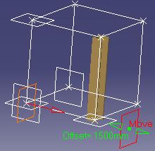
28 The component and all three parts are copied at the same location as the original. You will now simply move the component to its new position. 28. Move the component just created to its correct location: Double-click the root product Select the Translation or Rotation icon Select the component just created using Copy / Paste In the Move dialog box, translate the component -800 mm along the Y axis, click Apply to see the result and then OK when satisfied.


 to display the toolbar containing the Plane command. 3. Double-click the Plane icon.")
29 Creating Plates with Openings This task shows you how to create and place two plates. Plates are positioned with respect to existing structures. Plate contours and openings are sketched: the Plate command lets you access the Sketcher workbench directly. First, however, you must define the planes on which you will create the plates. This is done in the Part Design workbench. 1. Switch to the Part Design workbench: Select the root product. Select Start -> Mechanical Design -> Part Design. 2. Select View -> Toolbars -> Reference Elements (Extended) to display the toolbar containing the Plane command. 3. Double-click the Plane icon. The Plane Definition dialog box appears. 4. Set Plane type to Through two lines. 5. Select an edge on the first column. 6. Select an edge on the second column, then click OK in the dialog box. The first plane is created.


30 7. Define the other plane you need. 8. Click the Plane icon again when done. 9. Double-click the root product to return to the Equipment Support Structures workbench. 10. Click the Plate icon. The Plate Definition dialog box appears. 11. Select one of the planes you have just created as the support plane for the plate. 12. Enter a plate thickness of 10 mm. 13. Click the Sketcher icon in the Plane Definition dialog box to sketch the plate contour and opening. The Sketcher workbench opens. 14. Click the Rectangle icon and sketch the plate contour. 15. Click the Ellipse icon and sketch the contour for the opening in the plate.


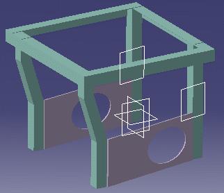
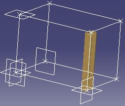
31 16. Click the Exit Workbench icon when done. You return to the Structure Foundations Design workbench and the system previews the plate and opening. 17. Click OK in the Plate Definition dialog box to create the plate. 18. Repeat to create the second plate. Your foundation now looks like this:
32
33 Bracing the Foundation This task shows you how to add a brace to complete your foundation. The brace is positioned with respect to existing structures. 1. Double-click the Member icon. The Linear Definition dialog box appears. 2. Define brace characteristics: Set Type to H-Brace. Set Anchor point to Top left. Set Orientation to 270 degrees. 3. Set Direction to Parallel to YZ plane to create the brace in this plane. Start and end points will be defined by creating points on existing members. You may need to restore the Point Definition dialog box. 4. Define the start point: In Point Definition dialog box, click Point on member. The dialog box expands to include an Offset field. Select bottom end of the member from which you want to start the brace. Selecting the bottom end computes the offset from this end. Enter an offset of 200 mm in the dialog box. Click OK when satisfied.

34 5. Check, and adjust if necessary, section orientation. Right-clicking the member in the specification tree gives you access to the contextual menu and lets you make any necessary adjustments to the orientation and anchor point of your member. 6. Define the end point: In Point Definition dialog box, click Point on member. Select the top end of the member at which to end the brace. Selecting the top end computes the offset from this end. Enter an offset of 200 mm. Click OK when satisfied.


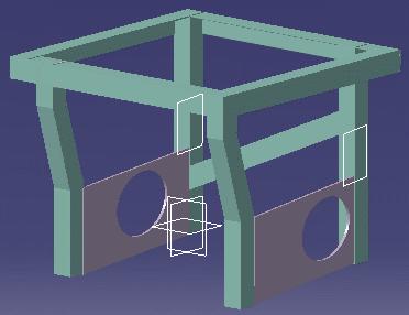
35 The brace is created and your foundation looks like this: Notice that brace ends are not neatly finished. 7. Click the Member icon again when done.

36 Defining How Member Ends are Cut All that is left now is to define how brace ends are to be cut. 8. Double-click the Joint icon. The Joint Definition dialog box appears. 9. Set Type to Weld cut. 10. Select the member you want to trim: one of the braces. 11. Select the member to which you want it trimmed: one of the uniform columns, then click OK. The brace is trimmed to the column.


37 12. Repeat to trim the brace to the column at the other end, and click OK. The brace is trimmed nicely at both ends. The specification tree is updated to include cutback information. 13. Click the Joint icon again when done.
38

39 Generating a BOM This task shows you how to generate a bill of materials in the form of an Excel report from your model. The macro SectionQuantityList.CATScript that we will use to generate the BOM is delivered in the /install_folder/code/command folder. For more information on the installation folder, see the Infrastructure User's Guide. 1. Make a multiple selection of all the structures in your document. 2. Select Tools- >Macro- >Macros... The Macro dialog box appears. 3. Select the macro: Set Macro in to External File Click Select in the dialog box Navigate in the Select External File dialog box and select the CATScript. The CATScript is listed in the Macro dialog box. 4. Select the macro in the Macro dialog box and click Run to run it. An Excel spreadsheet opens and the bill of material is generated. It looks like this:
40 User Tasks Creating a Foundation Document Creating a Grid Creating Support Structures Modifying, Joining & Moving Exporting Wireframe Skeletons Generating BOMs Equipment Support Structure Package in Knowledge Expert Managing User Sections Interoperability with CATIA V5 Working with ENOVIA LCA: Optimal CATIA PLM Usability
41 Creating a Foundation Document This task shows you how to typify your document as a foundation document. 1. Select Equipments & Systems ->Equipment Support Structures from the Start menu. The Equipment Support Structures workbench is displayed. 2. Click the Foundation icon: The Foundation Definition dialog box appears. 3. Identify your foundation. 4. Click OK when done. The document is characterized as a foundation document. You can now create your structures. If desired, you can create a grid to help you. Are you working with ENOVIA V5? If yes, it is important to read the Working in ENOVIA V5 section before starting, in order to be fully integrated with ENOVIA V5
42 Creating a Grid Using grids lets you position structures more easily as well as design in context. You can create structures referencing geometrical grid elements. Design changes can then be introduced by modifying the grid and updating the structure in consequence. This task shows how to create a new grid that you can then use as a construction aid to create members. A grid is made of wireframe elements (lines, points and planes) and is identified in the specification tree. It can be created using either the Cartesian or Polar coordinate system. 1. Click the Grid icon. The Grid Definition dialog box appears. 2. Enter a name for the grid you want to create in the Name box: The grid will be identified by this name in the specification tree. 3. Select Relative or Absolute in the Mode list to define the grid construction mode. In the absolute mode, grid planes are positioned with respect to the grid origin. Planes can be repositioned independently of one another. In the relative mode, grid planes are positioned with respect to each other. Moving a plane impacts other planes offset from that plane. This is the default mode.


43 4. Enter absolute coordinates in the Origin box or select a point in the geometry area to define the grid origin. If you select a point, the point is identified in the dialog box. The grid origin is now linked to this point. 5. In the First direction in XY plane box: In the Cartesian tab, enter H and V coordinates to define the local x-axis. Or, Click the Polar tab and enter an angle to define the polar axis. Or, Select a line in the geometry area. Note: By default, the local x-axis is positioned along the absolute x-axis. If you select a line, the line is identified in the dialog box. The first direction is now linked to this line. 6. Specify grid coordinates: In the Cartesian tab, specify the distance between grid points and number of points along x, y and z axes. Or, In the Polar tab, specify the radius, amplitude and spacing along the z-axis as well as the number of grid points in each case. Note: Clicking More expands the dialog box and lets you enter up to three more different combinations to define your grid.


: Keep link with selected object")
44 7. Click OK to create the grid. The grid is created and is identified in the specification tree. Grid planes are associative: moving a plane will update the grid. This is useful when modifying a structure: move a plane (double-click to edit) and see the structure defined using the grid updated when you double-click the root product in the specification tree if the following options were set in the General tab in the Options dialog box (Tools -> Options, Infrastructure -> Part Infrastructure): Keep link with selected object Synchronize all external references for update.
45
46 Creating Support Structures Equipment Support Structures allows you to design structure assemblies from linear and curved members and plates. Associativity To ensure associativity between the supports you create and any underlying wireframe geometry used as construction geometry, you must check the following options before creating supports: Keep link with selected object Synchronize all external references for update These options are to be foundi n the General tab of the Options dialog box (Tools -> Options..., Infrastructure -> Part Infrastructure). Settings Do not forget to define settings for access to standard catalog sections and available sections (Tools -> Options..., Equipment & Systems -> Equipment Support Structures). Design Mode Do not forget to switch to Design Mode (Edit -> Representations) to create supports. Double-clicking Commands Double-clicking commands keeps dialog boxes open and lets you create more than one structure at any one time. Make up a list of sections: Double-click the Section icon and select sections you need from the Catalog browser. Create members: Set parameters in the Member Definition dialog box then define where the member starts and ends. Create infills: Set parameters in the Infill dialog box then select the two structures between which you want to create infills. Create members on supports:set parameters in the Member on Support dialog box then select the support. Create plates: Set parameters in the Plate Definition dialog box, select a support then define the contour of the plate. Create end plates: Set parameters in the End Plate Definition dialog box, select the end of the structure at which you want to place the end plate.
. User-defined sections.")
.")
47 Making Up a List of Sections Sections used to create structures can be: Standard catalog sections Samples of standard catalogs are supplied with the product. Sections in these catalogs are parametric sketches associated with design tables (CSV-type Excel files). User-defined sections. Before you start working, make up a list of the catalog and/or user sections you will need. Catalog and user sections can then be accessed directly via the Section list of the appropriate dialog box. In Equipment Support Structures, sections are saved in a folder defined in your settings (sections storage path). In Structure Functional Design, sections are saved in a folder managed as a project resource (structure sections path). This task shows how to make up a list of standard catalog and user sections suited to your needs. No sample document is provided. Standard Catalog Sections 1. Double-click the Section icon. The Catalogs Browser dialog box opens letting you browse and preview the contents of the current catalog. The default location for the standard section catalogs is../os/startup/components/structuralcatalogs To choose another catalog, click the Browse another catalog icon to open the File Selection dialog box.


48 2. Browse the list of families in the Catalog Browser dialog box and double-click the family of interest, for example Tees. 3. Browse the list of shapes and select the section of interest, for example WT12x49, then click OK in the dialog box. For information on options in the Catalog Browser, see Using Catalogs in the Infrastructure User's Guide. 4. Repeat until you have selected all catalog sections you are likely to need. Copies of the sections are added to the sections folder defined in your settings in the case of Equipment Support Structures, or in the project management file in the case of Structure Functional Design. The Other Section... option in the Section list of the appropriate dialog box also gives you access to the catalog browser. User-defined Sections User-defined sections are of two types: Parametric sections stored in a user catalog and accessed in the same way as standard catalog sections. Resolved sections saved directly in the sections folder containing the list of sections. Both types of section can be created using the Sketcher. For more information on sketcher capabilities, see the Sketcher User's Guide. 1. To make up a list of user sections: Double-click the Section icon and proceed as above for standard catalog sections. Or, Save resolved sections directly in the sections folder defined in your settings in the case of Equipment Support Structures, or in the project management file in the case of Structure Functional Design.
49

50 Creating Members This task shows how to create linear members. No sample document is provided. 1. Click the Member icon. The Linear Member Definition and Point Definition dialog boxes appear. Note: Double-click the icon to keep the dialog box and create more than one member. 2. In the Type list, select the type of member you want to create: Column Beam H-Brace V-Brace. You can define custom member types using the Tools -> Option command. 3. In the Section list, select the shape you want to use. Click: One of the available section names, or Other section... to access catalog sections not already listed. The first time you enter the workbench, you must initialize the section list with catalog and/or user sections. Right-click in the dialog box box and select Section properties from the contextual menu to view geometrical and mechanical properties of the selected section. The Section Properties dialog box appears:
51 Select the Mechanical Properties tab: 4. In the preview or in the Anchor point list, select the desired point at which to anchor the section along the support axis. Note: Since the section selected is symmetrical, gravity anchor points coincide with standard anchor points. The illustration to the right shows standard and gravity anchor points for a channel shape section. 5. In the Orientation box, use the arrows to change the angular dimension value and orient the section around its anchor point: The Orientation field is updated in 90 degree increments by default. Right-click in this field to change the step. In the illustrations below, the anchor point is top left.

52 Right-click in the Orientation field to change the orientation step or range: 6. In the Direction list, select how you want to place the member. You can place members using points, a plane or an axis. Unspecified Planes and Lines When placing parallel to or on an unspecified plane, click the Direction box and select a plane before defining the member limits. The member is placed parallel to or projected onto the plane. When placing parallel to an unspecified line, click the Direction box and select a line before defining the member limits. Specifying an Offset to XY, YZ or XZ Plane Specifying an offset is particularly useful when creating members between two existing structures. The offset is computed along the normal to the defined plane. Click the Offset checkbox and enter a value or use the arrows to change the value in the Offset field. You can enter a positive or a negative value. Select wireframe elements or two existing structures. This option is only available when the selected direction is parallel to the XY, YZ or XZ plane. 7. Define the limits of the member you want to create: You can define the start and end limits of a member in a variety of different ways, by Entering coordinates Selecting wireframe elements Selecting points created in the Sketcher workbench


53 Selecting the end of an existing structure: The member starts or ends at the end point of the support axis of the selected structure. Selecting one of the vertices of a section Creating a point on an existing structure using the Point on member option in the Point Definition dialog box Specifying a length Entering Coordinates Enter point coordinates in the Point Definition dialog box or in the power input field in the status bar. You can combine coordinates and selection of wireframe elements when defining start and end points for members. Selecting Wireframe Elements Wireframe elements are useful construction aids. To create a construction grid, see Creating a Grid. Select a wireframe element in the geometry area. You can combine coordinates and selection of wireframe elements when defining start and end points for members. Creating a Point on an Existing Structure Click Point on member in the Point Definition dialog box. Select the end of an existing structure: the offset is defined from the selected end. Enter an offset in the dialog box or slide the offset handler. Click OK.


54 Specifying a Length Enter point coordinates or select a wireframe element to define the start point. Click the Length checkbox and enter a value or use the arrows to change the value in the Length field. Indicate in the geometry area to identify the direction. A preview of the member guides you as you create. Any changes in the member definition are immediately reflected in the preview. Parallel to the z-axis; moving cursor in negative direction Anchor point: Bottom left Default orientation. Parallel to the z-axis; moving cursor in positive direction Anchor point: Center Orientation: 90 degrees The member is created and has the characteristics defined in the Member Definition dialog box. The linear member is added to the specification tree. To modify a member, right-click it in the specification tree and select the appropriate command from the contextual menu. You can translate, rotate and manipulate members.

55 Creating Infills This task shows how to create infills between two members. No sample document is provided. 1. Click the Infill icon. The Infill Definition dialog box appears. 2. In the Type list, select the type of infill you want to create: Column Beam H-Brace V-Brace You can define custom member types using the Tools -> Option command. 3. In the Section list, select the shape you want to use. Click: One of the available section names, or Other section... to access catalog sections not already listed. The first time you enter the workbench, you must initialize the section list with catalog and/or user sections. Right-click in the dialog box and select Section properties from the contextual menu to view geometrical and mechanical properties of the selected section.
56 The Section Properties dialog box appears: Select the Mechanical Properties tab: 4. In the preview or in the Anchor point list, select the desired point to anchor the section along the support axis.
57 Note: Since the section selected is symmetrical, gravity anchor points coincide with standard anchor points. The illustration to the right shows standard and gravity anchor points for a channel shape section. 5. In the Orientation box, use the arrows to change the angular dimension value and orient the section around its anchor point: The Orientation field is updated in 90 degree increments by default. Right-click in this field to change the step. In the illustrations below, the anchor point is top left. Right-click in the Orientation field to change the orientation step or range: 6. Specify the number of infills you want to place in the Number box by scrolling to a new value with the up and down arrows. 7. (Optional) Define a support plane: Click the Support box and select a wireframe plane or a planar face of an existing element. If no support is defined, infills are created in the plane defined by the selected structures. 8. In the Position box, select Relative to position infill sections with respect to the plane defined by the selected structures Or, Absolute to take infill section orientation into account. Relative Absolute 9. (Optional) In the Offset box, set an offset with respect to the plane in which the infills will be created. 10. Select the first structure (reference 1).

58 11. Select the second structure (reference 2). The point at which you select structures is important. The system determines the end nearest this point and computes infill spacing along the selected structure from this end. A preview guides you as you create. Any changes in the infill definition are immediately reflected in the preview. Options in the Spacing boxes let you define the distances between infills as well as between infills and the ends of selected structures. 12. Specify infill spacing: To have infills placed at equal distances along structure 1: In the Mode box, select Equal. To specify infill position and spacing with respect to the first structure (reference 1): In the Mode box, select Defined In the D1 box, enter a value or use the arrows to change the value to specify the distance from the end of the structure to the first infill In the D2 box, enter a value or use the arrows to change the value to specify the distance between infills In the D3 box, enter a value or use the arrows to change the value to specify the distance from the last infill to the other end of the structure. Note: In the Defined mode, you must enter distances D1 and D2. Distance D3 is generally deduced by the system. To define infill position and spacing with respect to the second structure (reference 2): In the Mode box, select the appropriate option: Equal: infills are placed at equal distances along structure 2 Perpendicular to 1: infills are placed perpendicular to structure 1 Perpendicular to 2: infills are placed perpendicular to structure 2 Same as 1: D1 and D3 distances are applied when placing infills along structure 2.

59 Use the Same as 1 option when structures are not parallel to keep the same distances between infills and the ends of structures. 13. When satisfied, click OK to create the infills. Infills are created and have the characteristics defined in the Infill Definition dialog box. Infills are added to the specification tree. To modify infills, right-click in the specification tree and select the appropriate command from the contextual menu. You can translate, rotate and manipulate infills.

60 Creating Members on Supports This task shows how to route straight and curved members along an existing support. The member can be trimmed to planes, intersection elements or faces of existing structures selected as limits. This command is particularly useful when creating curved members. Open the MemberOnSupport.CATProduct document. 1. Click the Member on Support icon. The Member on Support dialog box appears. 2. In the Type list, select the type of member you want to create: Column Beam H-Brace V-Brace. You can define custom member types using the Tools -> Option command. 3. In the Section list, select the shape you want to use. Click: One of the available section names, or Other section... to access catalog sections not already listed. The first time you enter the workbench, you must initialize the section list with catalog and/or user sections.
61 Right-click in the dialog box and select Section properties from the contextual menu to view geometrical and mechanical properties of the selected section. The Section properties dialog box appears:
62 Select the Mechanical Properties tab: 4. In the preview or in the Anchor point list, select the desired point to anchor the section along the support axis. Note: Since the section selected is symmetrical, gravity anchor points coincide with standard anchor points.
63 The illustration to the right shows standard and gravity anchor points for a channel shape section. 5. In the Orientation box, use the arrows to change the angular dimension value and orient the section around its anchor point: The Orientation field is updated in 90 degree increments by default. Right-click in this field to change the step. In the illustrations below, the anchor point is top left. Right-click in the Orientation field to change the orientation step or range: 6. Select a support curve or line: Note: Multi-selection of supports is available. To visualize selected supports, click the List icon or right-click in the Support field and select Elements list from the contextual menu. The Elements list dialog box opens showing selected supports. Support curves or lines are wireframe elements created using the Grid V5 Wireframe and Surface Design product. Note: You cannot select elements of a sketch. command or the The member will be routed along the selected support(s). A preview guides you as you create. Any changes in member definition are immediately reflected in the preview. Arrows identify the direction along which a positive offset is calculated.

 In the Offset box, enter a value or use the arrows to change the value to offset limit 1 or limit 2 by the specified distance.")
64 Right-click in the geometry area to access the contextual menu allowing you to specify the number of sections previewed. 7. To orient the section with respect to a reference curve or surface, click the Reference box and select the desired curve or surface. Specifying a reference lets you create twisted members. 8. Select the first limit to which you want to trim the member 9. Select the second limit. 10. (Optional) In the Offset box, enter a value or use the arrows to change the value to offset limit 1 or limit 2 by the specified distance. Limits can be planes, intersection elements or the faces of existing structures. 11. Click OK to create the curved member. The member is created and has the characteristics defined in the Member on Support dialog box. The curved member is added to the specification tree.

65 To modify a member, right-click it in the specification tree and select the appropriate command from the contextual menu. You can translate, rotate and manipulate members.


66 Creating Plates This task shows how to create different types of plate, except end plates. Open the CreatingPlates.CATProduct document. The sample documents looks like this: 1. Click the Plate icon. The Plate Definition dialog box appears. 2. In the Type list, select the desired type of plate. You can define custom plate types using the Tools -> Option command. 3. In the Thickness box, use the arrows to change the thickness value or enter a value directly in the box. Plate thickness can be managed via design tables. A sample table in text format is supplied with the product. If the user defines the path to the sample table, only pre-defined thicknesses from the table can be selected. To gain access to the sample table, define the path in your settings (Tools-> Options, Equipment & Systems, Equipment Support Structures tab).


67 Click the Design table icon in the Plate Definition dialog box. The Design Table dialog box appears. Select the desired thickness, then click OK. If you change the thickness in the design table, all plates of this thickness linked to the design table will be updated to the new value. You can modify or add to the sample table, or, if needed, create a new table. The thickness table is a simple text file. 4. Select a support: The support can be a plane or the face of an existing structure. 5. In the Offset box, use the arrows to change the distance value or enter a value directly in the box to create the plate parallel to the support, offset by the specified distance. 6. Define the contour of your plate: Click the Sketcher icon to open the Sketcher workbench Sketch the plate contour in the support plane Exit the sketcher. For more information on the Sketcher, see the Sketcher User's Guide. A sketch must not contain more than one external plate contour. You can, however, sketch one external and several internal contours in the same sketch.


68 The plate is created. You can now make any on-thefly modifications and see them reflected in the preview. Or, Select points, lines or edges in the document to define the plate contour. An arrow normal to the support and identifying the direction of extrusion is displayed. As you select elements, a preview appears to guide you. Elements you select are projected onto the support plane. Click Apply or double-click to create the plate. 7. Select the arrow or click the Reverse direction option in the dialog box to extend the plate in the opposite direction from that shown. 8. Adjust the plate thickness. 9. Click Apply when satisfied.


69 You can also modify the shape of your plate and for example create a corner using the Sketcher. 10. Click OK when done. The plate is created and has the characteristics defined in the Plate Definition dialog box. The plate is added to the specification tree. 11. Create another structure between the two plates using a plate face as support. Your structure now looks like this:
70 To redefine a plate, right-click it in the specification tree and select Definition from the contextual menu. You can translate, rotate and manipulate plates.


71 Creating End Plates This task shows how to create a special type of plate called an end plate. Click here to find out how to create other types of plate. No sample document is provided. 1. Click the End-Plate icon. The End Plate Definition dialog box appears. 2. In the Type list, select the desired type of plate. 3. Define the length, width and thickness of the plate using arrows to change the values or entering values directly in boxes. The length and width are defined with respect to the local axis system of the structure, for example, in the case of an I shape, the width is defined along the x-axis parallel to the flange and the length along the y-axis parallel to the web. 4. Select the end of the structure at which you want to place the end plate: A preview appears. An arrow identifies the direction of extrusion. To reverse the direction of extrusion, click the arrow or click Reverse direction in the dialog box. You can adjust all plate characteristics in the dialog box, then click Apply to preview the results.


72 5. Click OK when satisfied. The end plate is created as defined and is added to the specification tree. Creating Several End Plates by Multiple Selection Simply Cntrl-click to select more than one structure end and have several end plates created in one go. Changing the direction of extrusion or other plate characteristics applies to all end plates.
73 Modifying, Joining & Moving Modify members: Right-click the member in the specification tree and select the desired type of modification, then make appropriate changes. Modify plates: Right-click the plate in the specification tree and select Definition from the contextual menu, then make appropriate changes. Join structures: Select the cut in the Joint Definition dialog box, specify an offset, then select members. Split structures: Select the structure to split, then the splitting element. Translate structures: Select a structure and enter offset values in the Move dialog box. Rotate structures: Select a structure, choose the axis of rotation and enter an angle in the Move dialog box. Manipulate structures: Define the move in the Manipulation Parameters dialog box, select a structure and drag. Important: Translation or Rotation and Manipulation commands are for unconstrained structures, i.e. structures to which no geometric nor assembly constraints have been set.
74 Modifying Members You can: Modify the type, section, anchor point and orientation of members (Definition). Add a positive or negative offset at member ends (Extend). Stretch unconstrained linear members (Stretch). Flip the section (Flip). All modifications are done via the contextual menu on structures selected in the specification tree. Note: You cannot select structures you want to modify in the geometry area. This task shows how to modify members. No sample document is provided. 1. In the specification tree, right-click the member you want to modify and select the type of modification you want to make from the contextual menu. If you have created a large number of structures, right-click the structure of interest in the geometry area then select the Center Graph command to find your structure in the specification tree. Modifying Member Definition using Multiple Selection You can modify the definition of several members in one go by Cntrl-clicking members in the specification tree. Note: Extend, Stretch and Flip commands are not available if a multiple selection is made. 2. Make the required modification. Definition: make your selection(s) in the Definition dialog box that appears and click OK when done.


75 Extend: the Limits Definition dialog appears. Set new values in offset boxes and/or select a new limit where appropriate then click OK when done. For structures created by specifying a length, you can also modify the length value.


76 Stretch: a graphic manipulator is displayed letting you stretch the unconstrained linear member along the main axes of the section. Stretch your structure and click OK in the Point Definition dialog box when done. Important: This command is only available for unconstrained linear members, i.e. those created by entering coordinates or with the Keep link with selected object option de-activated). Flip: select this command to flip an asymmetric section.

77 Modifying Plates You can modify the definition of both plates and end plates. All modifications are done via the contextual menu on structures selected in the specification tree. Note: You cannot select structures you want to modify in the geometry area. This task shows how to change plate characteristics. No sample document is provided. 1. Right-click the plate you want to modify and select Definition from the contextual menu. If you have created a large number of structures, right-click the structure of interest in the geometry area then select the Center Graph command to find your structure in the specification tree. Modifying Plate Definition using Multiple Selection You can modify the definition of several plates in one go by Cntrl-clicking plates in the specification tree. This capability is not available for end plates. Note: Plate contours can only modified one by one. 2. Make the required modification in the Definition dialog box that appears and click OK when done. If you selected a plate: If you selected an end plate:

78 The table below summarizes what you can modify: Multiple selection Plates Yes, but plate contours can only be modified singly End plates No Type Yes Yes Thickness Yes Yes Offset Yes No Contour Yes Length & width Direction of extrusion Yes Yes
79 Joining Structures Joints define how member ends are cut and are associative. If you modify the member, the joint is automatically recomputed. This task shows how to specify the type of joint between members. No sample document is provided. 1. Click the Joint icon. The Joint Definition dialog box appears. 2. In the Type list, select the desired type, for example Normal cut. Types available are: None: no cut. This option lets you remove a previously applied cut. Weld cut: a cutting plane is used to cut the member you want to trim. Miter cut: members are perpendicular with ends cut at an angle. Normal cut: ends of members are cut perpendicular to the support axis. Trim to plane: the selected member is trimmed to a plane. The trimming plane can be a plane, face, surface, plate or another member.


80 Remove: material is removed from the member you want to trim to accommodate the other member. The result differs depending on the first member selected. 3. In the Offset box, use the arrows to change the offset value or enter a value directly in the box to offset the member you want to trim from the trimming member. 4. Select the member you want to trim. 5. Select the member serving as limit (trimming member) or, for the Trim to plane option, a plane, face, surface, plate or shape. It is important to select members in the correct order. 6. Click Apply to create the cut. Members are cut back as specified in the dialog box and the joint is identified in the specification tree. Curved Members Curved members cannot be trimmed because the cutting plane may intersect the curve at more than one location.

81 Normal & Weld Cuts To apply normal or weld cuts to all member ends in the following configuration: Join members 1 & 2, 2 & 3 and 3 & 4 using normal or weld cuts. When joining members 4 & 1, select member 1 as the member to trim. Note: The cut cannot be made if member 4 is selected as the member to trim.


82 Miter Cut You cannot apply a miter cut to a member that is already mitered. If the member (member1) you want to cut is already mitered: Remove the cut using None Apply a miter cut to members 1 and 3.


83 Note: You can apply a normal or weld cut to a member that is already mitered.


84 Splitting Structures This task shows you how to split intersecting structures. 1. Click the Split icon. The Split Definition dialog box appears. 2. Select the structure you want to split. 3. Select the splitting element: The splitting element can be another structure, a line, a point or a plane. If a line or plane are chosen, the split is made at the intersection with the support axis of the structure you want to split. If a point is chosen, the point is mapped onto the support axis of the structure you want to split. 4. Click OK when done. The structure is split into two and a new entry added to the specification tree.


85 Associativity Split structures are associative, i.e. if you adjust the grid used to define the structures and update, the structures are updated too.

86 The new structure inherits the same properties (anchor point, material, orientation, etc.) as the original structure you split.

87 Translating Components This task will show you two ways to translate a component: by entering translation values by selecting geometrical elements to define a translation direction. If you are working in Assembly Design workbench, this task is P1-only. Using P2 configuration, you can rotate constrained components by means of the Shift key and the compass. The element to be translated must belong to the active component. The option Automatic switch to Design mode is available for this command. For more about this option, refer to Access to geometry in the Infrastructure User's Guide. Open the Moving_Components_01 document. 1. Click the Translate or Rotation icon: The Move dialog box is displayed. Either you specify an offset value between the element and x, y or z axis, or you select a geometric element to define the direction you need.


88 2. Select the component to be translated, that is CRIC_BRANCH_3. By Entering Values 3. Enter 50 mm as the offset value, in the Offset X field. The component will be translated along x axis. 4. Click Apply. The selected component is translated accordingly.
89 5. Click the Invert button to reverse the previous operation and translate the component in the opposite direction. The component is translated in the opposite direction. You can click Apply as many times as you wish to translate the component to the desired position. 6. Click OK to close the dialog box. 7. Repeat steps 1 and 2. By Selecting Geometric Elements 8. Click the Selection button to define a new translation with respect to a geometric element. The Translation tab contents is grayed out. If you select a line or a plane you need to enter a distance value. The translation is then done along the selected line or normal to the selected plane. Selecting two faces or planes assumes these elements are parallel. 9. Select the red and blue faces as shown. These faces are parallel.

90 The application computes the distance between these faces. The Offset field then displays this distance value: Offset X: 20mm Offset Y: 0mm Offset Z: 0mm 10. Click Apply to translate the blue component. You can apply this translation to any other components. You just need to select it and click the Apply button. 11. Click OK to exit.
91
92 Rotating Components This task will show you the two ways of rotating a component: by entering the rotation angle and specifying the rotation axis by selecting a geometric element as the rotation axis and entering the angle value If you are working in Assembly Design workbench, this task is P1-only. Using P2 configuration, you can rotate constrained components by means of the Shift key and the compass. The element to be rotated must belong to the active component. The option "Automatic switch to Design mode" is available for this command. For more about this option, refer to Access to geometry in the Infrastructure User's Guide. Open the Moving_Components_01 document. 1. Click the Translate or Rotation icon: The Move dialog box is displayed. Translation options are available. To find out how to translate components, refer to Translating Components. 2. Click the Rotation tab.


93 3. Select the component you wish to rotate, that is CRIC_BRANCH_1. Entering a Rotation Angle 4. For example, check the Axis Y option to specify the axis of rotation. 5. Enter 90 as the angle value in the Angle field.

94 The selected component is rotated accordingly. 7. Click OK to close the dialog box. 8. Repeat steps 1, 2 and 3. Selecting Geometry to Define the Axis of Rotation 9. Click the Selection button to define a new rotation with respect to a geometrical element. 10. Select the edge as shown to specify the new rotation axis. 11. Enter 90 in the Angle field.

95 12. Click Apply to rotate the red component. You can apply this rotation to any other components. You just need to select it and click the Apply button. 13. Click OK to exit.

96 Manipulating Components This task will show you how to manipulate a component. The Manipulate command lets you move a component freehand with the mouse. It is less constraining than the Translate Component and Rotate Component commands. See Translating Components and Rotating Components. The element to be manipulated must belong to the active component. Open the Moving_Components_02 document. 1. Click the Manipulate icon: The Manipulation Parameters dialog box appears. You can translate or rotate components using one of the following options: The first and second horizontal rows are reserved for translations. You can move your component along the x, y or z-axis as well as in the xy, yz and xz planes. The third row is reserved for rotations. You can rotate your component around the x, y or z- axis. The fourth column lets you specify the direction of your choice by selecting a geometric element. This element defines the direction of the move or the axis of rotation. 2. Click the Drag along Y axis icon: 3. Select Set1 as the component to be translated.

97 4. Drag Set1. The component is translated in the Y axis direction. 5. Now select CRIC_FRAME and click Drag around Y axis icon: 6. Drag the component. You are rotating it around the Y axis.
98 7. Check the option With respect to constraints. If you repeat the previous operation, you will notice that you are not allowed to do it. The existing parallelism constraint prevents you from moving the component. 8. Click OK to exit. Use the Shift key and the compass to manipulate constrained components. Flexible components cannot be moved via the Manipulate command.
 CATPart. 1. Click the Export icon. The Save As dialog box appears. 2.")
99 Exporting Wireframe Skeletons This task shows you how to export simplified wireframe geometry (the skeleton and section) of your structures. Two formats are proposed: STEP AP203 (only if you have the appropriate license) CATPart. 1. Click the Export icon. The Save As dialog box appears. 2. Click the Save as type list and select the desired format. You can save the simplified wireframe geometry as: a V5 CATPart (.CATPart). The CATPart is added to the original document. a STEP AP203 document (.stp) if you have the appropriate license. If you don't have a STEP AP203 license, then this format is not proposed and you can only save the skeleton as a CATPart document. 3. For STEP documents, specify the location of the document to be saved and, if necessary, enter a file name. 4. Click Save to save the skeleton in a file in the desired format.


100 The STEP format lets you exchange data with other CAD systems to, for example, perform FEM analysis.

101 Generating BOMs You can generate Bills of Materials (BOMs) in the form of Excel reports or CSV files. This task shows how to use a sample macro to generate a BOM in the form of an Excel report. You can in this way obtain critical design information. The sample macro SectionQuantityList.CATScript is available in the /install_folder/code/command folder. For more information on the installation folder, see the Infrastructure User's Guide. 1.Select the structures for which you want to generate the BOM. Use the Edit ->Search command to assist you identify structures of interest. 2.Run the macro: Select Tools ->Macro ->Macros... Select the macro in the Macro dialog box and click Run to run the macro. You can also drag and drop the macro onto your toolbar using Tools ->Customize ->Commands ->Macros. Then simply click the icon to run the macro. The BOM is generated in the form of an Excel report. Product Structure and Equipment Support Structures attributes are listed. SectionQuantityList.CATScript For more information on the CATScript itself, see Structure on the Automation Documentation Home Page. '// COPYRIGHT DASSAULT SYSTEMES 1999 '//============================================================================ '// '// Language="VBSCRIPT" '// Sample of macro to extract the Bill Of Material '// '//============================================================================ '// This CATScript assumes that the user has selected Structural objects '// from the Specification Viewer or the 3D Window. '// '// It is advised that the user understand the VBScript and VBA concepts before '// attempting to modify the code to suit their needs. Microsoft Excel 97 '// provides excellent documentation on the use of VBScript and VBA. '//============================================================================ dim excel as AnyObject dim workbooks as AnyObject dim workbook as AnyObject dim sheets as AnyObject dim sheet as AnyObject dim exceltemplate as String dim exceltemplatepath as String dim strwb as Workbench dim strserv as AnyObject dim currentrow as integer
102 '// '// Default path of the excel file template '// strcatcommandpath = CATIA.SystemService.Environ("CATCommandPath") exceltemplate = "SectionQuantityListTemplate.xls" exceltemplatepath = strcatcommandpath + "\" + exceltemplate '// '// User customization of the attributes which will be extracted '// dim nbcolumns as integer nbcolumns = 12 dim column(12) column(1) = "MemberType" column(2) = "SectionName" column(3) = "FamilyName" column(4) = "CatalogName" column(5) = "Length" column(6) = "PlateType" column(7) = "Thickness" column(8) = "Surface" column(9) = "Wet area" column(10) = "Volume" column(11) = "Material" column(12) = "Mass" dim pospartnumber as integer pospartnumber = 1 dim posname as integer posname = 2 '// '// Start Excel '// Sub StartEXCEL() Err.Clear On Error Resume Next Set excel = GetObject (,"EXCEL.Application") If Err.Number <> 0 Then Err.Clear Set excel = CreateObject ("EXCEL.Application") End If excel.application.visible = TRUE set workbooks = excel.application.workbooks set workbook = workbooks.add(exceltemplatepath) If Err.Number <> 0 Then Dim strmessage strmessage = "Error Loading Template File:" + exceltemplatepath + Chr(13) strmessage = strmessage + Chr(13) + "Check the following..." + Chr(13) strmessage = strmessage + "(1)Template File has read-write capability" + Chr(13) strmessage = strmessage + "(2)Template File path is valid" msgbox (strmessage) End If set sheets = workbook.worksheets set sheet = sheets("parameters list") End Sub '// '// Exit Excel
103 '// Sub EndEXCEL() workbook.close excel.quit End Sub '// '// Write in Excel '// Sub WriteInExcel(iRow, icolumn, istring) On Error Resume Next if (Len(iString) > 0) then dim whichcolumn as integer whichcolumn = 0 Select Case icolumn Case "PartNumber" whichcolumn = 1 Case "Name" whichcolumn = 2 End Select if (whichcolumn = 0) then dim NotTheSame as Integer dim i as Integer NotTheSame = 0 for i = 1 to nbcolumns NotTheSame = StrComp(column(i), icolumn, 0) if (NotTheSame = 0) then whichcolumn = 2 + i Exit for end if Next end if sheet.cells(irow, whichcolumn) = istring sheet.cells(irow, whichcolumn).select end if End Sub
104 Sub PrintParameters(iProduct) dim parameters as Parameters dim param as Parameter dim nbparam as integer On Error Resume Next WriteInExcel currentrow, "PartNumber", iproduct.partnumber WriteInExcel currentrow, "Name", iproduct.name dim RefProduct as Product set RefProduct = iproduct.referenceproduct set parameters = iproduct.referenceproduct.parameters nbparameters = parameters.count dim i as Integer dim parm as Parameter if (nbparameters > 0) then for i = 1 to nbcolumns if (column(i) = "Length") then dim length as double length = strwb.strcomputeservices.getlength(iproduct) if (length > 0) then WriteInExcel currentrow, column(i), length end if Elseif (column(i) = "Thickness") then dim thickness as double thickness = strwb.strcomputeservices.getthickness(iproduct) if (thickness > 0) then WriteInExcel currentrow, column(i), thickness end if Elseif (column(i) = "Surface") then dim surface as double surface = strwb.strcomputeservices.getsurface(iproduct) if (surface > 0) then WriteInExcel currentrow, column(i), surface end if Elseif (column(i) = "Wet area") then dim wetarea as double wetarea = strwb.strcomputeservices.getwetarea(iproduct) WriteInExcel currentrow, column(i), wetarea Elseif (column(i) = "Volume") then dim volume as double volume = strwb.strcomputeservices.getvolume(iproduct) WriteInExcel currentrow, column(i), volume Elseif (column(i) = "Mass") then dim mass as double mass = strwb.strcomputeservices.getmass(iproduct)
105 WriteInExcel currentrow, column(i), mass Elseif ( column(i) = "Material") then set param = parameters.getitem(refproduct.name & "\" & column(i)) if (Err.Number <> 0) then set param = Nothing if (Not(param Is Nothing)) then WriteInExcel currentrow, column(i), param.valueasstring end if Else set param = parameters.getitem(column(i)) if (Err.Number <> 0) then set param = Nothing if (Not(param Is Nothing)) then WriteInExcel currentrow, column(i), param.valueasstring end if end if Next end if End Sub Sub CATMain() On Error Resume Next StartExcel dim product as Product dim nbproduct as integer nbproduct = 0 currentrow = 2 dim doc as Document dim sel as Selection set doc = CATIA.ActiveDocument set strwb = doc.getworkbench("strworkbench") set strserv = strwb.strcomputeservices set sel = doc.selection set product = sel.findobject("catiaproduct") Do Until(product Is Nothing) nbproduct = nbproduct + 1 PrintParameters(product) set product = sel.findobject("catiaproduct") if (Err.Number <> 0) then set product = Nothing currentrow = currentrow + 1 Loop ' EndExcel End Sub
106 Generating BOMS in the form of CSV Files Bills of Materials can also be generated in the form of CSV files. This is particularly useful when working on UNIX. A sample macro QuantityListCSV.CATScript has likewise been delivered in the /install_folder/code/command folder. Run this macro as described above. QuantityListCSV.CATScript '// COPYRIGHT DASSAULT SYSTEMES 1999 '//============================================================================ '// '// Language="VBSCRIPT" '// Sample of macro to extract the Bill Of Material '// '//============================================================================ '// This CATScript assumes that the user has selected Structural objects '// from the Specification Viewer or the 3D Window. '// '// It is advised that the user understand the VBScript and VBA concepts before '// attempting to modify the code to suit their needs. Microsoft Excel 97 '// provides excellent documentation on the use of VBScript and VBA. '//============================================================================ dim excel as AnyObject dim workbooks as AnyObject dim workbook as AnyObject dim sheets as AnyObject dim sheet as AnyObject dim exceltemplate as String dim exceltemplatepath as String dim strwb as Workbench dim strserv as AnyObject dim currentrow as integer '// '// User customization of the attributes which will be extracted '// dim nbcolumns as integer nbcolumns = 12 dim column(12) column(1) = "MemberType" column(2) = "SectionName" column(3) = "FamilyName" column(4) = "CatalogName" column(5) = "Length" column(6) = "PlateType" column(7) = "Thickness" column(8) = "Surface" column(9) = "Wet area" column(10) = "Volume" column(11) = "Material" column(12) = "Mass" '// '// Find parameters value '// Sub PrintParameters(iText as TextStream, iproduct as Product) dim parameters as Parameters dim userparameters as Parameters dim param as Parameter
107 dim nbparam as integer dim textline as string On Error Resume Next textline = Cstr(iProduct.PartNumber) & ";" textline = textline & Cstr(iProduct.Name) & ";" dim RefProduct as Product set RefProduct = iproduct.referenceproduct set parameters = iproduct.referenceproduct.parameters set userparameters = iproduct.referenceproduct.userrefproperties Dim plate As StrPlate nameprod = iproduct.name Dim plates as StrPlates Set plates = iproduct.parent.parent.gettechnologicalobject("structureplates") if (not(plates is nothing)) then set plate = plates.item(nameprod) end if nbparameters = parameters.count dim i as Integer dim parm as Parameter if (nbparameters > 0) then for i = 1 to nbcolumns Err.Clear ' length to cut for a member if (column(i) = "Length") then dim length as double length = strwb.strcomputeservices.getlength(iproduct) if (length > 0) then textline = textline & Cstr(length) end if ' thickness for a plate Elseif (column(i) = "Thickness") then dim thickness as double if (Not(plate Is Nothing)) then thickness = plate.standardthickness textline = textline & Cstr(thickness) end if ' surface for a plate Elseif (column(i) = "Surface") then dim surface as double surface = strwb.strcomputeservices.getsurface(iproduct) if (surface > 0) then textline = textline & Cstr(surface) end if ' wet area for structure objects Elseif (column(i) = "Wet area") then dim wetarea as double wetarea = strwb.strcomputeservices.getwetarea(iproduct)
108 if (wetarea > 0) then textline = textline & Cstr(wetarea) end if ' volume for structure object Elseif (column(i) = "Volume") then dim volume as double volume = strwb.strcomputeservices.getvolume(iproduct) if (volume > 0) then textline = textline & Cstr(volume) end if ' mass for structure object Elseif (column(i) = "Mass") then dim mass as double mass = strwb.strcomputeservices.getmass(iproduct) if (mass > 0) then textline = textline & Cstr(mass) end if ' material Elseif (column(i) = "Material") then set param = parameters.getitem(refproduct.name & "\" & column(i)) if (Err.Number <> 0) Then Set param = Nothing if (Not(param Is Nothing)) then textline = textline & Cstr(param.ValueAsString) end if ' user attribute Else set param = parameters.item(column(i)) if (Err.Number <> 0) Then Set param = Nothing ' f(x) attribute if (Not(param Is Nothing)) then textline = textline & Cstr(param.ValueAsString) ' user propertie on product else Err.Clean set param = userparameters.item(column(i)) if (Not(param Is Nothing)) then textline = textline & Cstr(param.ValueAsString) end if end if end if textline = textline & ";" Next end if ' write the line itext.write(textline) itext.write(chr(10)) End Sub '// '// Main '//
109 Sub CATMain() On Error Resume Next dim filesystem as FileSystem set filesystem = CATIA.FileSystem dim bomfile as File set bomfile = filesystem.createfile("e:\tmp\bom.txt", true) dim text as TextStream set text = bomfile.openastextstream("forwriting") dim product as Product dim nbproduct as integer nbproduct = 0 dim doc as Document dim sel as Selection set doc = CATIA.ActiveDocument set strwb = doc.getworkbench("strworkbench") set strserv = strwb.strcomputeservices set sel = doc.selection set product = sel.findobject("catiaproduct") Do Until(product Is Nothing) nbproduct = nbproduct + 1 PrintParameters text, product set product = sel.findobject("catiaproduct") if (Err.Number <> 0) then set product = Nothing Err.clean end if Loop text.close End Sub

110 Equipment Support Structure Package in Knowledge Expert A Equipment Support Structure package is supported by Knowledge Expert. This package can be accessed via the object browser and objects, attributes and methods in the package used in expert relations. The package contains the following objects: StrFoundationExt STRMember STRPlate For information on object attributes and methods, see Equipment Support Structure in the Using the Object Libraries section of Using Knowledge Expert Tools (basic tasks) in the Knowledge Expert User's Guide.
111 Managing User Sections Sketching Profiles for User Sections Defining Anchor Points for User Sections Creating & Completing Parametric Section Catalogs
. 2. Select the xy working plane in the geometry area or specification tree. The Sketcher workbench is displayed.")
112 Sketching Profiles for User Sections This task shows how to sketch profiles for user sections using Sketcher capabilities. No sample document is provided. 1. Start the Sketcher workbench (Start ->Mechanical Design ->Sketcher). 2. Select the xy working plane in the geometry area or specification tree. The Sketcher workbench is displayed. User sections created using Sketcher capabilities must be created in the xy plane. 3. Sketch your profile, for example use the Circle icon to sketch a simple circle that will give a round bar or circular tubing section: Point where you want to place the center of the circle. Drag to set the radius. Click when satisfied. Note: It is recommended that profile dimensions match actual section dimensions. 4. If desired, set constraints. 5. Exit the sketcher. 6. Using File -> Save, save the sketch as a CATPart document in the folder dedicated to storing available sections defined in your settings (see the Customizing section of this guide). Your sketch now appears as a resolved section in the Section list of the appropriate dialog box. You are now ready to use it to create a structure.

113 For more information on sketching profiles and setting constraints, see the Sketcher User's Guide.
114 Defining Anchor Points for User Sections Anchor points can be defined on user-defined parametric sections. Note: All resolved sections automatically inherit the defined anchor point. This task shows how to define an anchor point. No sample document is provided. 1. Edit the sketched section. 2. If the anchor point you want to define does not correspond to an existing point of the sketch, create an appropriate construction point. 3. Rename the point: Right-click the point and select Properties from the contextual menu. Select the Feature Properties tab in the Properties dialog box. Rename the point using the prefix catstr, for example catstruseranchorpoint. 4. Exit the sketcher, then save the sketch as a CATPart document (File ->Save). 5. Return to the Structure Design workbench: The new anchor point is automatically added to the Anchor point list. All user anchor points are accompanied by the following symbol: to distinguish them from standard anchor points. Anchor points WebSideLeft, WebSideRight and WebCenter are supplied with the product for L, T and bulb sections. These anchor points are considered user anchor points and share the same anchor point symbol:
115 Creating & Completing Parametric Section Catalogs This task shows how to create a user catalog for parametric sections. You can create user catalogs in three different ways: Using the Catalog Editor with one sketch corresponding to one family and linked to one design table. With a Part Family in Batch Mode with one sketch corresponding to one family and linked to one design table. In Batch Mode where one sketch is used for several families and design tables are not linked to the sketch. These catalogs are built in the same way as the sample catalogs supplied with the product. Sample CatScript documents are provided to illustrate the batch mode and will be mentioned below at the appropriate step in the task. They are to be found in the online documentation filetree in the common functionalities sample folder, cfysm/samples. Creating a Catalog using the Catalog Editor This first task introduces the Catalog Editor workbench which provides interactive commands to create your own catalogs. 1. Make a USER directory with the same name as your catalog and sub-directories for sketches and design tables: USER/Sketches USER/DesignTables. 2. Sketch the profiles for your user sections and store in the USER/Sketches directory. Standard sketches of parametric sections (I, U, L, T, double U, double L, bulb and tube shapes) supplied with the product are located in the directory install_folder/startup/components/structuralcatalogs/sketchs. 3. Create design tables, naming the header in the first column PartNumber. Note: You can create design tables in two ways: Independently of sketches, in which case you must link tables to sketches (ensuring that design table column headers correspond to sketch parameters). Based on the sketches, in which case no linking is necessary. Design tables contain the geometric parameters used to generate the section. 4. Use the Catalog Editor to create your catalog: From the Start menu, select Infrastructure ->Catalog Editor to open the Catalog Editor workbench. Use the Add Part Family icon for Structure Design catalogs. For more information, see Creating a Catalog using the Catalog Editor in the Infrastructure User's Guide. Creating a Catalog with a Part Family in Batch Mode

116 1. Make a USER directory with the same name as your catalog and sub-directories for sketches, design tables and CSV files: USER/Sketches USER/DesignTables USER/CSVFiles USER/VBScript. 2. Sketch the profiles for your user sections and store in the USER/Sketches directory. Standard sketches of parametric sections (I, U, L, T, double U, double L, bulb and tube shapes) supplied with the product are located in the directory install_folder/startup/components/structuralcatalogs/sketchs. 3. Create design tables, naming the header in the first column PartNumber. Note: You can create design tables in two ways: Independently of sketches, in which case you must link tables to sketches (ensuring that design table column headers correspond to sketch parameters). Based on the sketches, in which case no linking is necessary. Design tables contain the geometric parameters used to generate the section. 4. Create a CSV-type file for Chapters. CSV files map family names to appropriate family catalogs. Chapters correspond to the first level in a catalog and provide a way of classifying other chapters or families. Typical CSV file: CHAPTER;DIN;I_SectionCatalogDIN; Keywords;Family; Types;String; ;Quadrat_Hohlprofile;e:\users\jcm\StructuralCatalogs\USER\Quadrat_Hohlprofile.catalog ;Rechteck_Hohlprofile;e:\users\jcm\StructuralCatalogs\USER\Rechteck_Hohlprofile.catalog 5. Create ENDCHAPTER and CHAPTER CATScripts. Sample CATScripts are given below. They are to be found in the online documentation filetree in the common functionalities sample folder, cfysm/samples. ENDCHAPTER Open the file USER_EndChapterswithPartFamily.CATScript. In our example, the content looks like this:
117 '// COPYRIGHT DASSAULT SYSTEMES 1999 '//============================================================================ '// '// Language="VBSCRIPT" '// To build catalog from a parametric part '// '//============================================================================ '// Major interface used: '// '// interface VB Name Remarks '// '// CATIACatalogDocument CatalogDocument create catalog '// '//============================================================================ Option Explicit '****************************************************************************** ' GLOBAL variable declarations section '****************************************************************************** Dim strginputpath Dim strgoutputpath '@@@@@@@@@@@@@@@@@@@@@@@@@@@@@@@@@@@@@@@@@@@@@@@@@@@@@@ '// User customizable sections '@@@@@@@@@@@@@@@@@@@@@@@@@@@@@@@@@@@@@@@@@@@@@@@@@@@@@@ Const NBEndChapter = 2 Dim strarrayendchapter (2) Dim strarraymodelfile (2) Dim strarraycatalogfile (2) ' Sub InitEndChapterArray () ' ' Name of the description displayed in the catalog browser ' strarrayendchapter(1) = "Tees" strarrayendchapter(2) = "Equal Angles" ' ' Name of the.catpart defining the sketches ' strarraymodelfile(1) = "TShape" strarraymodelfile(2) = "LShape" ' ' Name of the generated files.catalog used in the USER.CATScript ' strarraycatalogfile(1) = "USER_Tees" strarraycatalogfile(2) = "USER_Equal_Angles" End Sub ' Sub GetPath () ' strginputpath = InputBox("Path of the models directory:", _ "Input path for model files", _ "e:\users\jcm\user\sketches\") strgoutputpath = InputBox("Path of the catalog output directory:", _ "Output path for Catalogs", _ "e:\users\jcm\user\") End Sub ' ' Sub CATMain() '
118 Dim objcatalogdoc As Document Dim intk As Integer Dim strchaptername As String Dim strmodelname As String Dim strcatalogname As String ' InitEndChapterArray ' GetPath ' On Error Resume Next For intk = 1 to NBEndChapter strmodelname = strginputpath & strarraymodelfile (intk) & ".CATPart" strchaptername = strarrayendchapter (intk) strcatalogname = strgoutputpath & strarraycatalogfile (intk) & ".catalog" Set objcatalogdoc = CATIA.Documents.Add("CatalogDocument") ' Calls the method on Catalog to create inside the catalog document ' a chapter from the Design Table objcatalogdoc.createchapterfromdesigntable strchaptername, strmodelname ' Saves the catalog document objcatalogdoc.saveas strcatalogname ' Closes the catalog document objcatalogdoc.close Next 'For intk MsgBox "Press OK to quit", 0, "CATALOG CREATION COMPLETED" End Sub '/////////////////////////////////////////////// CATMain If you want to use it, copy it and change the User customizable sections to adapt them to your environment, or copy a sample CATScript from the one of the standard catalogs supplied with the product and change it. CHAPTER Open the file USER_Chapter.CATScript. In our example, the content looks like this: '// COPYRIGHT DASSAULT SYSTEMES 1999 '//============================================================================ '// '// Language="VBSCRIPT" '// To build catalog '// '//============================================================================ '// Major interface used: '// '// interface VB Name Remarks '// '// CATIACatalogDocument CatalogDocument create catalog '// '//============================================================================ Option Explicit '****************************************************************************** ' GLOBAL variable declarations section '****************************************************************************** Dim strginputpath Dim strgoutputpath '@@@@@@@@@@@@@@@@@@@@@@@@@@@@@@@@@@@@@@@@@@@@@@@@@@@@@@ '// User customizable sections '@@@@@@@@@@@@@@@@@@@@@@@@@@@@@@@@@@@@@@@@@@@@@@@@@@@@@@ Const NBGCSVFile = 1 Dim strarraygcsvfile (1) ' Sub InitCSVFileArray () ' strarraygcsvfile(1) = "USER" End Sub '/////////////////////////////////////////////// InitCSVFileArray ' Sub GetPath () ' strginputpath = InputBox("Path of the catalog input directory:", _
119 "Input path for CSV files", _ "e:\users\jcm\user\csvfiles\") strgoutputpath = InputBox("Path of the catalog output directory:", _ "Output path for Catalogs", _ "e:\users\jcm\user\") End Sub '/////////////////////////////////////////////// GetPath ' Sub CATMain () ' Dim objcatalogdoc As Document Dim intk As Integer Dim strcsvfile Dim strcatalogfile InitCSVFileArray GetPath On Error Resume Next For intk = 1 to NBGCSVFile strcsvfile = strginputpath & strarraygcsvfile (intk) & ".csv" strcatalogfile = strgoutputpath & strarraygcsvfile (intk) & ".catalog" Set objcatalogdoc = CATIA.Documents.Add("CatalogDocument") ' Generate catalog objcatalogdoc.createcatalogfromcsv strcsvfile,strcatalogfile Next 'For intk MsgBox "Press OK to quit", 0, "CATALOG CREATION COMPLETED" End Sub '/////////////////////////////////////////////// CATMain If you want to use it, copy it and change the User customizable sections to adapt them to your environment, or copy a sample CATScript from the one of the standard catalogs supplied with the product and change it. 6. You are now ready to run the batch operation: Start a Version 5 session Select Tools ->Macro ->Macros... In the Macro dialog box, set Macro in to External File Select the appropriate CATScript, then click Run. It is important to run the CATScript generating the families (END CHAPTERS) before the one generating the chapter (CHAPTER) since the chapter references the families. Creating a Catalog in Batch Mode 1. Make a USER directory with the same name as your catalog and sub-directories for sketches, design tables and CSV files: USER/Sketches USER/DesignTables (this sub-directory must be named DesignTables) USER/CSVFiles USER/VBScript. 2. Sketch the profiles for your user sections and store in the USER/Sketches directory. Standard sketches of parametric sections (I, U, L, T, double U, double L, bulb and tube shapes) supplied with the product are located in the directory install_folder/startup/components/structuralcatalogs/sketchs. 3. Create design tables. Note: Do not link design tables to sketches. Design tables contain the geometric parameters used to generate the section.
120 4. Create CSV-type files for End Chapters and Chapters. CSV files map section names to appropriate parametric sketches. END CHAPTER Conventions End chapters correspond to catalog families. A family is a set of components. For example, ENDCHAPTER: Name;Icon;DesignTable; If the design table is not linked to a sketch, the name of the design table must be the last parameter in the first line starting ENDCHAPTER. The first keyword must be Section The full path name of documents must be given. Typical CSV file: ENDCHAPTER;HEA;I_SectionStructureI;OTUA_HEA; Keywords;Section; Types;String; HEA100;HEA100;e:\users\jcm\StructuralCatalogs\Sketches\IShape.CATPart HEA120;HEA120;e:\users\jcm\StructuralCatalogs\Sketches\IShape.CATPart HEA140;HEA140;e:\users\jcm\StructuralCatalogs\Sketches\IShape.CATPart CHAPTER Conventions Chapters correspond to the first level in a catalog and provide a way of classifying other chapters or families. Typical CSV file: CHAPTER;DIN;I_SectionCatalogDIN; Keywords;Family; Types;String; ;Quadrat_Hohlprofile;e:\users\jcm\StructuralCatalogs\USER\Quadrat_Hohlprofile.catalog ;Rechteck_Hohlprofile;e:\users\jcm\StructuralCatalogs\USER\Rechteck_Hohlprofile.catalog 5. Create ENDCHAPTER and CHAPTER CATScripts. Sample CATScripts are given below. They are to be found in the online documentation filetree in the common functionalities sample folder, cfysm/samples. ENDCHAPTER Open the file USER_EndChaptersStandard.CATScript. In our example, the content looks like this: '// COPYRIGHT DASSAULT SYSTEMES 1999 '//============================================================================ '// '// Language="VBSCRIPT" '// To build catalog '// '//============================================================================ '// Major interface used: '// '// interface VB Name Remarks '// '// CATIACatalogDocument CatalogDocument create catalog '// '//============================================================================ Option Explicit '****************************************************************************** ' GLOBAL variable declarations section '****************************************************************************** Dim strginputpath Dim strgoutputpath '@@@@@@@@@@@@@@@@@@@@@@@@@@@@@@@@@@@@@@@@@@@@@@@@@@@@@@ '// User customizable sections '@@@@@@@@@@@@@@@@@@@@@@@@@@@@@@@@@@@@@@@@@@@@@@@@@@@@@@ Const NBGCSVFile = 2 Dim strarraygcsvfile (2) ' Sub InitCSVFileArray () '
121 strarraygcsvfile(1) = "Equal_Angles" strarraygcsvfile(2) = "Tees" End Sub '/////////////////////////////////////////////// InitCSVFileArray ' Sub GetPath () ' strginputpath = InputBox("Path of the catalog input directory:", _ "Input path for CSV", _ "e:\users\jcm\user\csvfiles\") strgoutputpath = InputBox("Path of the catalog output directory:", _ "Output path for CSV", _ "e:\users\jcm\user\") End Sub '/////////////////////////////////////////////// GetPath ' Sub CATMain () ' Dim objcatalogdoc As Document Dim intk As Integer Dim strcsvfile Dim strcatalogfile InitCSVFileArray GetPath On Error Resume Next For intk = 1 to NBGCSVFile strcsvfile = strginputpath & strarraygcsvfile (intk) & ".csv" strcatalogfile = strgoutputpath & strarraygcsvfile (intk) & ".catalog" Set objcatalogdoc = CATIA.Documents.Add("CatalogDocument") ' Generate catalog objcatalogdoc.createcatalogfromcsv strcsvfile,strcatalogfile Next 'For intk MsgBox "Press OK to quit", 0, "CATALOG CREATION COMPLETED" End Sub '/////////////////////////////////////////////// CATMain If you want to use it, copy it and change the User customizable sections to adapt them to your environment, or copy a sample CATScript from the one of the standard catalogs supplied with the product and change it. CHAPTER Open the file USER_Chapter.CATScript. In our example, the content is as illustrated above. f you want to use it, copy it and change the User customizable sections to adapt them to your environment, or copy a sample CATScript from the one of the standard catalogs supplied with the product and change it. 6. You are now ready to run the batch operation: Start a Version 5 session Select Tools ->Macro ->Macros... In the Macro dialog box, set Macro in to External File Select the appropriate CATScript, then click Run. It is important to run the CATScript generating the families (END CHAPTERS) before the one generating the chapter (CHAPTER) since the chapter references the families. Completing Parametric Section Catalogs
122 This task shows how to add sections to existing catalogs. To add sections to existing catalogs, you must rename the path of linked documents in CSV files because these files contain the full path name. To do so, one Excel file per sample catalog containing an appropriate macro is provided. For example, the Excel file for the OTUA catalog is OTUA_hierarchy.xls. Excel files are located in the CsvFiles directory. 1 Edit the Commands sheet of the appropriate Excel file, entering the necessary information. Note: The first sheet named Data contains all CSV files in the catalog. 2. Click Modify absolute path of pointed CATPart in CSV files to rename the path. 3. Add new sections. 4. Generate the catalog as above.
123 Interoperability with CATIA V5 Produce drawings: Provides information on producing drawings using structure drawing options and generative view styles. Create cutouts: Edit a plate, then switch to the Part Design workbench. Sketch the contour of the cutout then create it using the Pocket icon. Create flanges: Edit a plate, then switch to the Sheet Metal Design workbench. Use Walls Recognition and Flange Definition icons. Create assembly constraints: Switch to the Assembly Design workbench and place desired constraints on structures. You can also sketch profiles for user sections in the Sketcher workbench.
124 Producing Drawings using the Options Dialog Box You can generate structural drawings using: Structure drawing options in the Options dialog box (see below) Generative view styles. This task shows how to generate structural drawings using structure drawing options in the Options dialog box. A Drafting license For more information on drafting capabilities, see the Generative Drafting User's Guide. 1. Open your 3D Document. 2. Specify your settings before you start: Select Tools -> Options -> Equipment & Systems and then the Structure Drawing tab. 3. In addition, you will need to set the following drafting options: In the Options dialog box, select Mechanical Design -> Drafting -> Generation Check Project 3D wireframe, Project 3D points and Apply 3D specifications. 4. Create a new drawing: Select Start -> Mechanical Design -> Drafting. You switch to the Drafting workbench and the New Drawing Creation dialog box appears. Select the view you want to create. Click OK in the New Drawing Creation dialog box. 5. Click the Front View or Advanced Front View icon. The Advanced Front View command lets you enter a name and scale. The recommended scale is 1: Return to the 3D document and select a plane of a 3D part or a plane surface to define the projection plane and the drawing view. A 3D view is previewed on your drawing. Use the drafting manipulator to adjust the view. 7. Click inside the view to generate the view.

125 Producing Drawings Generative view styles are used to produce structural drawings. These view styles let you customize the appearance of drawings via a set of parameters defined in an XML file. It is the administrator's job to provide suitable styles. For more information on generative view styles and other drafting capabilities, see the Generative Drafting User's Guide. This tasks shows you how to produce drawings using generative view styles. A Generative Drafting license. 1.Open your 3D document.


126 2.Specify your settings before you start: Select Tools ->Options ->Mechanical Design->Drafting->Administration Click to clear the Prevent generative view style creation option This activates generative view style functionalities. 3.Create a new drawing: Select Start -> Mechanical Design -> Drafting. You switch to the Drafting workbench and the New Drawing Creation dialog box appears. Select the view you want to create. Click OK in the New Drawing Creation dialog box. 4. Click the Front View icon. The Generative View Style toolbar is automatically displayed. 5.Select one of the available styles from the list. 6.Return to the 3D document and select a plane of a 3D part or a plane surface to define the reference plane. 7.Click inside the sheet to generated the view.
127 Use Technological Feature Dimensions commands to dimension functional stiffeners and stiffening in the graphic replacement mode.
128 Using Generative View Styles This section intends to give you information about generative view style parameters for the following applications: Common to all applications Equipment Support Structures Structure Functional Design Ship Structure Detail Design. Customizing these parameters affects the appearance of your drawings and is an administrator task. The following sample XML files are supplied: EquipmentSupportStructureSample.xml StructureFunctionalSample.xml StructureDetailSample.xml Sample files are located in../os/resources/standard/generativeparameters. These files can be customized by the administrator. The administrator must also set the generative parameter "wireframe" located under the Drafting-> Generate node in the DefaultGenerativeStyle.xml to Yes so that the user obtains suitable drawings using generative view styles. Appropriate application licenses including one for Generative Drafting are required. For information on how to create views using generative view styles, how to set view style parameters or more generally on administering generative view styles, see the Generative Drafting User's Guide. Common Symbols You can customize generative view style parameters for the reference plane system and connections. These parameters are shared by all structure applications. Reference Plane System
129 Parameter Value Description ShowReferencePlaneSystem Yes/No Specifies whether or not to show the reference plane system. No (default value): No reference plane system Yes: Shows the reference plane system RestrictedToTheBoundingBox Yes/No Specifies whether or not to limit the reference plane system to the bounding box of generated objects. No (default value): No restriction Yes: Restricts the reference plane system to the bounding box GridsetPosition 0/1 Specifies the location of the reference plane system on the drawing: 0 (default value): The reference plane system is generated in the same location as the set of planes 1: The reference plane system is generated to the left of or below the view HorizontalOffset real Specifies the horizontal offset of the reference plane system from the view. Default value: 20 mm VerticalOffset real Specifies the vertical offset of the reference plane system from the view. Default value: 20 mm GridSetLineType integer Specifies the linetype to use for the reference plane system. Default value: 1 (solid linetype). TickSize real Specifies the size (in mm) of tick marks representing frames. Default value: 2.0 AnnotationStyle integer Specifies how to annotate frame tick marks. 0: No annotation 1 (default value): Frame names 2: Offset from origin including units 3: Offset from origin, no units given AnnotationSize real Specifies the size (in mm) of annotations. Default value: 2.0 if model units for length are mm. If model units for length are cm, set the size to 0.2 AnnotationStep AnnotationStart integer Specifies at what intervals to place frame text annotations. Default value: 1 - each tick mark has a frame annotation. integer Specifies starting frame for text annotations. Default value: 1 Connection Parameter Value Description
130 Extraction Yes/No Specifies whether or not to draw connection symbols. No (default value): no connection symbols. Yes: connection symbols will be drawn. WeldSeam AngularTolerance real Specifies the angle (in degrees) determining what weld seam symbol to use. If the angle between plates is less than the specified value: If the angle is greater than or equal to the specified value: Default value: 1.0 Note: Weld seam symbols are only generated if a connection exists. UseSymbol Yes/No Specifies whether or not to use a symbol for the connection. No (default value): no symbol used. Yes: a symbol defined by the SymbolicRepresentation parameter will be drawn. WeldSeam / S_Representation / LongWeldSeam Offset (4) real Applies to long weld seams. Symbols are placed on the straight seam. Default value: 3.0 mm
131 Thickness (5) real Applies to long weld seams. Default value: 3.0 mm WeldSeam / S_Representation / ShortWeldSeam Gap (1) real Applies to short weld seams. Symbols are positioned at each end of the curved seam. Default value: 1mm Length (2) real Applies to short weld seams. Default value: 5 mm WeldSeam / SymbolicRepresentation / WeldSeam ChapterName character string Specifies the name of the Structure Drawing Symbols Catalog chapter containing connection symbols. Default value: Connections DetailName The chapter must exist in the Structure Drawing Symbols Catalog which is managed as a project resource. character string Specifies the name of the symbol to represent the connection. Default value: S_5x1
132 The symbol must exist in the Structure Drawing Symbols Catalog which is managed as a project resource. WeldSeam / SymbolicRepresentation / WeldSeamWithKnuckle ChapterName character string Specifies the name of the Structure Drawing Symbols Catalog chapter containing connection symbols. Default value: Connections DetailName The chapter must exist in the Structure Drawing Symbols Catalog which is managed as a project resource. character string Specifies the name of the symbol to represent the knuckle connection. Default value: SwKnuckle_5x1 TightHiddenPlate The symbol must exist in the Structure Drawing Symbols Catalog which is managed as a project resource. StraightLineType integer Specifies the linetype of the line representing tight hidden plates. Note: Tight hidden plate lines are only generated if a connection exists. The administrator must create a bi-dimensional plate linetype of a crosshatch pattern: Select Tools -> Standards to start the standards editor. Select the Drafting category and open the standard of interest from the File drop-down list. Expand nodes and select the LineTypes parameter, then set a bi-dimensional linetype of a crosshatch pattern in the right-hand pane of the dialog box. CurvedLineType integer Specifies the linetype of the line representing hidden curved plates. The administrator must specify an existing mono-dimensional linetype. Note: Hidden curved plate lines are only generated if a connection exists. CurvedLineThickness integer Specifies the thickness to use for hidden curved plates. Equipment Support Structures You can customize generative view style parameters for: Members Plates.
133 Member Parameter Value Description Extraction Yes/No Specifies whether or not to project members. No: no projection. Yes (default value): members will be projected. GraphicReplacement Yes/No Specifies whether to generate a 3D representation or lines representing the trace of members. No (default value): 3D representation Yes: graphic replacement AngularToleranceForEndView real Defines the angle (in degrees) between the member section and the projection vector above which the member section is not projected. Default value: 15.0 (see illustration below) NearSideLinetype integer Specifies the linetype of the line representing the trace of visible members. Default value: 1 (solid linetype). SymbolsAtEndsOfProfile UseAnEndSymbol Yes/No Specifies whether or not to place a symbol at member ends. No: No symbol Yes (default value): Symbol used
134 ChapterName character string Specifies the name of the Structure Drawing Symbols Catalog chapter containing end symbols. Default value: Ends DefaultDetailName The chapter must exist in the Structure Drawing Symbols Catalog which is managed as a project resource. character string Specifies the name of the symbol to place at member ends. Default value: BlackFilledArrow_3x1.5 The symbol must exist in the Structure Drawing Symbols Catalog which is managed as a project resource. Plate Parameter Value Description Extraction Yes/No Specifies whether or not to project plates. No: no projection. Yes (default value): plates will be projected. GraphicReplacement Yes/No Specifies whether to generate a 3D representation or lines representing plates. No (default value): 3D representation Yes: graphic replacement Linetype integer Specifies the linetype of the line representing the plate. Default value: 1 (solid linetype). LineThickness integer Specifies the line thickness to use. Default value: 2 MaterialExtrusion MaterialThrowOrientation character string Specifies how to represent material throw orientation: None (default value): No material throw orientation represented. Tick mark (true width): Tick marks showing thickness is generated. Throw orientation (symbolic): A symbol identifying orientation is generated. Tick mark and throw orientation: A symbol identifying orientation and tick marks showing thickness are generated. MTOSymbolsChapterName character string Specifies the name of the Structure Drawing Symbols Catalog chapter containing material throw orientation symbols. Default value: MaterialOrientations MTO_DetailName The chapter must exist in the Structure Drawing Symbols Catalog which is managed as a project resource. character string Specifies the name of the material throw orientation symbol to generate. Default value: BlackFilledRectangle_5x1 The symbol must exist in the Structure Drawing Symbols Catalog which is managed as a project resource.
135 Structure Functional Design You can customize generative view style parameters for: Functional stiffeners Functional plates Functional pillars Functional openings. Functional Stiffener Parameter Value Description Extraction Yes/No Specifies whether or not to project stiffeners. No: no projection. Yes (default value): members will be projected. GraphicReplacement Yes/No Specifies whether to generate a 3D representation or lines representing the trace of stiffeners. No (default value): 3D representation Yes: graphic replacement AngularToleranceForEndView real Defines the angle (in degrees) between the member section and the projection vector above which the member section is not represented. Default value: 15.0 ShowNearSide Yes/No Specifies whether or not to generate the trace of near side stiffeners. Yes (default value): The trace of near side stiffeners is generated. No : No trace. NearSideLinetype integer Specifies the linetype of the line representing the trace of visible stiffeners. Default value: 1 (solid linetype). ShowFarSide Yes/No Specifies whether or not to generate the trace of hidden stiffeners. No (default value): No trace. Yes: The trace of hidden stiffeners is generated. FarSideLinetype integer Specifies the linetype of the line representing the trace of hidden stiffeners. Default value: 4 (phantom linetype). SymbolsAtEndsOfProfile UseAnEndSymbol Yes/No Specifies whether or not to place a symbol at member ends. No (default value): No symbol Yes: Symbol used ChapterName character string Specifies the name of the Structure Drawing Symbols Catalog chapter containing end symbols. Default value: Ends
136 DefaultDetailName character string The chapter must exist in the Structure Drawing Symbols Catalog which is managed as a project resource. Specifies the name of the symbol to use at member ends. Default value: BlackFilledArrow_3x1.5 MaterialExtrusion MaterialThrowOrientation MaterialExtrusion / MTO_Detail ChapterName character string character string The symbol must exist in the Structure Drawing Symbols Catalog which is managed as a project resource. Specifies how to represent material throw orientation: None (default value): No material throw orientation represented. Tick mark (true width): Tick marks showing thickness is generated. Throw orientation (symbolic): A symbol identifying orientation is generated. Tick mark and throw orientation: A symbol identifying orientation and tick marks showing thickness are generated. Specifies the name of the Structure Drawing Symbols Catalog chapter containing end symbols. Default value: MaterialOrientations DefaultDetailName character string The chapter must exist in the Structure Drawing Symbols Catalog which is managed as a project resource. Specifies the name of the material throw orientation symbol to use. Default value: BlackFilledRectangle_5x1 The symbol must exist in the Structure Drawing Symbols Catalog which is managed as a project resource. DrawDetailsByProfileType Yes/No Specifies whether or not to use a symbol representing the section for material throw orientation. Yes (default value): Symbol used depends on section type. Settings for each section type are included in the GVS file. No: DefaultDetailName symbol used. MaterialExtrusion / TickMark OffsetFromEndOfMember (6) real Default value: 7.0 Note: If the value is 0, the offset corresponds to 1/15 of the length of the stiffener. Length (7) real Default value: 5.0 Note: If the value is 0, the corresponding length is 1/15 of the length of the stiffener.
137 Functional Plate Parameter Value Description Extraction Yes/No Specifies whether or not to project members. No: no projection. Yes (default value): members will be projected. GraphicReplacement Yes/No Specifies whether to generate a 3D representation or lines representing plates. No (default value): 3D representation Yes: graphic replacement Linetype integer Specifies the linetype of the line representing the plate. Default value: 1 (solid linetype). LineThickness integer Specifies the line thickness to use. Default value: 2 MaterialExtrusion MaterialThrowOrientation character string Specifies how to represent material throw orientation: None (default value): No material throw orientation represented. Tick mark (true width): Tick marks showing thickness is generated. Throw orientation (symbolic): A symbol identifying orientation is generated. Tick mark and throw orientation: A symbol identifying orientation and tick marks showing thickness are generated. MTOSymbolsChapterName character string Specifies the name of the Structure Drawing Symbols Catalog chapter containing material throw orientation symbols. Default value: MaterialOrientations MTO_DetailName The chapter must exist in the Structure Drawing Symbols Catalog which is managed as a project resource. character string Specifies the name of the material throw orientation symbol to generate. Default value: BlackFilledRectangle_5x1 The symbol must exist in the Structure Drawing Symbols Catalog which is managed as a project resource. TM_Length real Specifies the tick mark symbol length. Default value: 5.0 mm Note: MaterialThrowOrientation must be set to 2 or 3. Functional Pillar Parameter Extraction Value Description Yes/No Specifies whether or not to project members. No: no projection. Yes (default value): members will be projected.
138 GraphicReplacement Yes/No Specifies whether or not to show pillar support curves. No (default value): no support curves. Yes: support curves are shown. Functional Opening Parameter Value Description GraphicReplacement Yes/No Specifies whether to generate a 3D representation or symbols representing openings. No (default value): 3D representation Yes: graphic replacement CenterlinesType character string Specifies how to represent the centerline. Three values are available: No centerlines Long centerlines (default value): Short centerlines: OblongOpeningsCenterlinesType character string Specifies how to represent centerlines for oblong openings. Two values are available. Note: The representation depends on the value used for CenterlinesType above. Double centerlines (default value): Double centerlines are illustrated with long and short CenterlinesType respectively. Single centerlines: Single centerlines are illustrated with long and short CenterlinesType respectively.
139 ButterflyThickness real Specifies the thickness (in mm) of the butterfly symbol. Default value: 4.0 Ship Structure Detail Design You can customize generative view style parameters for: Stiffening Beaming Plating Inserting Opening Stiffening Parameter Value Description Extraction Yes/No Specifies whether or not to project stiffeners. No: no projection. Yes (default value): members will be projected. GraphicReplacement Yes/No Specifies whether to generate a 3D representation or lines representing the trace of stiffeners. No (default value): 3D representation Yes: graphic replacement AngularToleranceForEndView real Defines the angle (in degrees) between the member section and the projection vector above which the member section is not represented. Default value: 15.0 ShowNearSide Yes/No Specifies whether or not to generate the trace of near side stiffeners. Yes (default value): The trace of near side stiffeners is generated. No : No trace.
140 NearSideLinetype integer Specifies the linetype of the line representing the trace of visible stiffeners. Default value: 1 (solid linetype). ShowFarSide Yes/No Specifies whether or not to generate the trace of hidden stiffeners. No (default value): No trace. Yes: The trace of hidden stiffeners is generated. FarSideLinetype integer Specifies the linetype of the line representing the trace of hidden stiffeners. Default value: 4 (phantom linetype). MaterialExtrusion MaterialThrowOrientation MaterialExtrusion / MTO_Detail ChapterName character string character string Specifies how to represent material throw orientation: None (default value): No material throw orientation represented. Tick mark (true width): Tick marks showing thickness is generated. Throw orientation (symbolic): A symbol identifying orientation is generated. Tick mark and throw orientation: A symbol identifying orientation and tick marks showing thickness are generated. Specifies the name of the Structure Drawing Symbols Catalog chapter containing material throw orientation symbols. Default value: MaterialOrientations DefaultDetailName character string The chapter must exist in the Structure Drawing Symbols Catalog which is managed as a project resource. Specifies the name of the material throw orientation symbol to use. Default value: BlackFilledRectangle_5x1 The symbol must exist in the Structure Drawing Symbols Catalog which is managed as a project resource. DrawDetailsByProfileType Yes/No Specifies whether or not to use a symbol representing the section for material throw orientation. Yes (default value): Symbol used depends on section type. Settings for each section type are included in the GVS file. No: DefaultDetailName symbol used. MaterialExtrusion / TickMark OffsetFromEndOfMember (6) real Default value: 7.0 Note: If the value is 0, the offset corresponds to 1/15 of the length of the stiffener. Length (7) real Default value: 5.0 Note: If the value is 0, the corresponding length is 1/15 of the length of the stiffener. SymbolsAtEndsOfProfile
141 UseAnEndSymbol Yes/No Specifies whether or not to place a symbol at member ends. No (default value): No symbol Yes: Symbol used ChapterName character string Specifies the name of the Structure Drawing Symbols Catalog chapter containing end symbols. Default value: Ends DefaultDetailName character string The chapter must exist in the Structure Drawing Symbols Catalog which is managed as a project resource. Specifies the name of the symbol to use at member ends. Default value: BlackFilledArrow_3x1.5 Beaming The symbol must exist in the Structure Drawing Symbols Catalog which is managed as a project resource. Parameter Value Description Extraction Yes/No Specifies whether or not to project members. No: no projection. Yes (default value): members will be projected. GraphicReplacement Yes/No Specifies whether or not to show support curves. No (default value): no support curves. Yes: support curves are shown. Plating Parameter Value Description Extraction Yes/No Specifies whether or not to project plates. No: no projection. Yes (default value): members will be projected. GraphicReplacement Yes/No Specifies whether to generate a 3D representation or lines representing plates. No (default value): 3D representation Yes: graphic replacement Linetype integer Specifies the linetype of the line representing the plate. Default value: 1 (solid linetype). LineThickness integer Specifies the line thickness to use. Default value: 2 MaterialExtrusion
142 MaterialThrowOrientation MTOSymbolsChapterName character string character string Specifies how to represent material throw orientation: None (default value): No material throw orientation represented. Tick mark (true width): Tick marks showing thickness is generated. Throw orientation (symbolic): A symbol identifying orientation is generated. Tick mark and throw orientation: A symbol identifying orientation and tick marks showing thickness are generated. Specifies the name of the Structure Drawing Symbols Catalog chapter containing material throw orientation symbols. Default value: MaterialOrientations MTO_DetailName character string The chapter must exist in the Structure Drawing Symbols Catalog which is managed as a project resource. Specifies the name of the material throw orientation symbol to use. Default value: BlackFilledRectangle_5x1 The symbol must exist in the Structure Drawing Symbols Catalog which is managed as a project resource. TM_Length real Specifies the tick mark symbol length. Default value: 5.0 mm Note: MaterialThrowOrientation must be set to 2 or 3. Inserting Parameter Value Description Extraction Yes/No Specifies whether or not to project members. No: no projection. Yes (default value): members will be projected. GraphicReplacement Yes/No Specifies whether to generate a 3D representation or lines representing plates. No (default value): 3D representation Yes: graphic replacement Linetype integer Specifies the linetype of the line representing the plate. Default value: 1 (solid linetype). LineThickness integer Specifies the line thickness to use. Default value: 2 MaterialExtrusion MaterialThrowOrientation character string Specifies how to represent material throw orientation: None (default value): No material throw orientation represented. Tick mark (true width): Tick marks showing thickness is generated. Throw orientation (symbolic): A symbol identifying orientation is generated. Tick mark and throw orientation: A symbol identifying orientation and tick marks showing thickness are generated.
143 MTOSymbolsChapterName character string Specifies the name of the Structure Drawing Symbols Catalog chapter containing material throw orientation symbols. Default value: MaterialOrientations MTO_DetailName character string The chapter must exist in the Structure Drawing Symbols Catalog which is managed as a project resource. Specifies the name of the material throw orientation symbol to use. Default value: BlackFilledRectangle_5x1 The symbol must exist in the Structure Drawing Symbols Catalog which is managed as a project resource. TM_Length real Specifies the tick mark symbol length. Default value: 5.0 mm Note: MaterialThrowOrientation must be set to 2 or 3. Opening Parameter Value Description GraphicReplacement Yes/No Specifies whether to generate a 3D representation or symbols representing openings. No (default value): 3D representation Yes: graphic replacement CenterlinesType character string Specifies how to represent the centerline. Three values are available: No centerlines Long centerlines (default value) Short centerlines
144 OblongOpeningsCenterlinesType character string Specifies how to represent centerlines for oblong openings. Two values are available. Note: The representation depends on the value used for CenterlinesType above. Double centerlines (default value): Double centerlines are illustrated with long and short CenterlinesType respectively. Single centerlines: Single centerlines are illustrated with long and short CenterlinesType respectively. ButterflyThickness real Specifies the thickness (in mm) of the butterfly symbol. Default value: 4.0

145 Creating Cutouts This task shows how to use Part Design capabilities to create cutouts. Cutouts are sketch-based features. It is strongly recommended that you use only standard Part Design commands, such as Pocket, Hole, Edge Fillet, Chamfer and Split. Using other commands may corrupt your document. For more information on Part Design capabilities, see the Part Design User's Guide. No sample document is provided. 1. Create a simple plate in the Equipment Support Structures workbench. 2. Right-click the plate you just created and select Edit from the contextual menu. 3. Switch to the Part Design workbench (Start ->Mechanical Design ->Part Design). 4. Select one of the plate faces to define the working plane. 5. Click the Sketcher icon to enter the Sketcher workbench. 6. Click the Elongated Hole icon to sketch your contour. 7. Click where you want to start the major axis, then drag. 8. Click when satisfied to create the major axis. 9. Drag and click again to define the minor axis. The cutout contour has been defined. 10. Exit the Sketcher. 11. Click the Pocket icon in the Part Design workbench. The Pocket Definition dialog box appears and your cutout is previewed.


146 12. Select Up to last in the Type box to define the limit of your cutout. The cutout feature will be extended from the sketch plane to the last face encountered. 13. Click OK to create the cutout.


147 Creating Flanges This task shows how to use Sheetmetal Design capabilities to create flanges. No sample document is provided. Sheetmetal capabilities are only available for plates. 1. Create a simple plate in the Equipment Support Structures workbench. 2. Right-click the plate you just created and select Edit from the contextual menu. 3. Switch to the Sheet Metal Design workbench (Start ->Mechanical Design ->Sheet Metal Design). 4. Click the Walls Recognition icon to have the plate recognized and access Sheet 5. Metal Design commands. Click the Flange Definition icon. The Flange Definition dialog box appears. 6. Select the edge on which you want to create a flange 7. Specify the flange radius, length and angle. In our example, we entered 2mm, 50mm and 120degrees respectively. 8. Click OK to create the flange. All Sheetmetal Design commands are available for plates. For more information on Sheetmetal Design capabilities, see the Sheetmetal Design User's Guide.

148 Creating Assembly Constraints Creating assembly constraints between structures lets you design in context and, in the case of changes, lets you control the propagation of modifications. Constraints can be placed as you work. Note: You can also design in context using a grid. Associativity: To ensure associativity, you must check the following options in the General tab of the Options dialog box (Tools -> Options..., Infrastructure -> Part Infrastructure): Keep link with selected object Synchronize all external references for update. This task shows how to place an offset constraint between two structures using the Assembly Design workbench. Open the CreatingAssemblyConstraints.CATProduct document. 1. Select the Assembly Design workbench (Start ->Mechanical Design ->Assembly Design). 2. Click the Offset Constraint icon 3. Select the inside face of one of the two columns. 4. Select the corresponding face on the other column. The Constraint Properties dialog box appears.


149 5. Enter an offset of 1000mm in the dialog box, then click OK. The two structures are now constrained by an offset distance of 1000mm. If you move one of the structures, the distance between the structures will remain 1000mm. 6. Click the Manipulation icon, then the Drag along Y axis icon in the dialog box that appears. 7. Select one of the structures and drag to a new position, then click OK in the dialog box.

150 8. Select the structure you moved, then click the Fix Component icon to fix it in space. 9. If necessary, click the Update icon to update your structure and take changes into account. The entire structure is updated to respect the offset constraint. For more information on creating constraints, see the Assembly Design User's Guide.
151 Working with ENOVIA LCA:Optimal CATIA PLM Usability When working with ENOVIA LCA, a new mode ensures that you only create data in CATIA that can be correctly saved in ENOVIA. ENOVIA LCA offers two different storage modes: Workpackage (Document kept - Publications Exposed) and Explode (Document not kept). All commands, except Foundation and Joint, work in either storage mode. The safe save mode means that certain commands (Foundation and Joint) are unavailable (i.e. grayed) on entering the workbench. These two commands have been configured to work in the Workpackage mode only. When working with ENOVIA LCA, the recommended methodology is: Send your ENOVIA document to CATIA. Work on your design in CATIA, whether from scratch or modifying an existing design. Save your CATIA data in ENOVIA in the Exposed mode. To ensure seamless integration, you must have both a CATIA and ENOVIA session running. 1. In the Product Structure workbench of CATIA V5, click the Init Enovia V5 Connection... icon to establish the connection between CATIA V5 and ENOVIA LCA. 2. In ENOVIA LCA, send your ENOVIA document to CATIA. For more information, see the CATIA / ENOVIA Interoperability User's Guide. 3. Work on your design in your CATIA V5 application. 4. In the Product Structure workbench of CATIA V5, click the Save Data in ENOVIA V5 Server... icon to save your CATIA data in ENOVIA. For more information, see the CATIA / ENOVIA Interoperability User's Guide.
152 Using Foundation and Joint Commands Foundations are defined at the root of the current CATIA document. 1. Send your ENOVIA document to CATIA. The ENOVIA PRC (product root class) is the root of the CATIA document. 2. Right-click the product workpackage under the PRC and select Open in new window. The product is opened in a new window as the root of the current CATIA document and you can now create your foundation and joints. 3. Define your foundation or joints. If, you created a foundation document in file-based mode: Save your work temporarily. Create a PRC in ENOVIA. Send the ENOVIA document to CATIA. Insert the product containing the work you saved temporarily. Save your work in ENOVIA.


153 Workbench Description The Equipment Support Structures Version 5 application window looks like this: Click the hotspots to see related documentation. Design Toolbar Assembly Toolbar Specification Tree
154 Design Toolbar See Creating a Foundation See Creating a Grid See Making Up a List of Sections See Creating Members See Creating Infills See Creating Members on Supports See Creating Plates See Creating End Plates See Joining Structures See Splitting Structures See Exporting Wireframe Skeletons
155 Assembly Toolbar See Translating Structures and Rotating Structures See Manipulating Structures

156 Specification Tree Icons displayed in the specification tree and specific to the Equipment Support Structures workbench are as follows: Typifies document as a foundation document. A linear or curved structure. Support axis along which the section is anchored. A flat structure.
157 Customizing Before you start you first session, you can customize the way you work to suit your habits. This type of customization is stored in permanent setting files: these settings will not be lost if you end your session. 1. Select the Tools -> Options command. The Options dialog box appears. 2. Select the Equipment & Systems category in the left-hand box. 3. Select the Equipment Support Structures sub-category. The General tab appears. This tab lets you define: Color options: default color for members and plates Material options: default materials for members and plates User types: create and manage member and plate user types Catalogs storage path: path of the folder containing sample standard catalog sections Sections storage path: path of the folder that will contain the list of available sections Thickness table path One other tab, located in the Equipment & Systems category, is also needed for Equipment Support Structures. Structural Drawing lets you customize how data extracted from the 3D document is presented on structural drawings. 4. Set options in these tabs according to your needs. 5. Click OK in the Options dialog box when done. As an administrator, you can manage structure settings via a VB macro.
158 Equipment Support Structures This page deals with the following categories of options in the General tab: Color Material User types Catalogs storage Sections storage Thickness table Color Use the Member and/or Plate color chooser to define the default color for members and plates respectively. By default, colors are as shown above. Material Select the default material for members and plates in the Member and/or Plate list. By default, materials are as shown above.

159 User types Lets you create and manage Member and Plate user types: Add: enter the name of the member or plate type then click Add to add user types. Remove: select the member or plate type in the list then click Remove to remove user types. By default, these options are left blank. Catalogs storage In the Path box, enter the path of the folder containing sample standard catalog sections supplied with the product: downloaddirectory/os/startup/components/structuralcatalogs where OS is the operating system, for example intel_a (Windows), Or, use [...] to locate the folder of interest. By default, this option is left blank.
160 Sections storage In the Path box, enter the full path of the folder that will contain the list of available sections, for example e:\section, or use [...] to locate the folder of interest. This folder will contain resolved user-defined sections stored here directly and any sample standard or user-defined catalog sections accessed via the Section command or the Other section... option. It is recommended that an empty directory be identified. By default, this option is left blank. Thickness table In the Path box, enter the path of the thickness table. A sample table, ThicknessListSample.txt, is supplied with the product. downloaddirectory/os/startup/components/structuralcatalogs/thickness Tables/ThicknessListSample.txt where OS is the operating system, for example intel_a (Windows), Or, use [...] to locate the folder of interest. By default, this option is left blank.
161 Structure Drawing The Structure Drawing tab contains the following categories of options: Molded forms: to define how molded forms will be represented on drawings. Members/Stiffeners: to define how members or stiffeners will be represented on drawings. Plates: to define how plates will be represented on drawings. Openings: to define how openings will be represented on drawings Midship designation Datum line Molded forms Linetype Defines the linetype used to represent molded forms on drawings. Select the desired linetype from the dropdown list. By default, this option is set to 0. Apply linetype on profile view only If this check box is selected, the selected linetype is applied to profile views only. By default, this check box is cleared. Members / Stiffeners
 for this line. By default, this check box is cleared and the 3D representation of members / stiffeners is generated on drawings.")
162 Graphic replacement If this check box is selected, a line representing the trace of visible members / stiffeners is generated on drawings. The user can specify the linetype (near side linetype) for this line. By default, this check box is cleared and the 3D representation of members / stiffeners is generated on drawings. Anglular tolerance Defines the value above which the member/ stiffener section is not represented. It is the angle between the member/ stiffener section and the projection vector. In the example below, the angular tolerance is 15. Near side linetype Defines the linetype to be used for the trace of visible members / stiffeners if the Graphic replacement option is selected. Select the desired linetype from the drop-down list. A solid line font is recommended.
 for this line. By default, this check box is cleared and hidden members / stiffeners are not shown on drawings.")
163 Show far side stiffeners If this check box is selected, a line representing the trace of hidden members / stiffeners, below a deck for example, is generated on drawings. The user can specify the linetype (far side linetype) for this line. By default, this check box is cleared and hidden members / stiffeners are not shown on drawings. Far side linetype Defines the linetype to be used for the trace of hidden members / stiffeners if the Show far side stiffeners option is selected. Select the desired linetype from the drop-down list. A phantom font is recommended. Generate arrowheads If this check box is selected, arrows are generated at ends of members / stiffeners. By default, this check box is cleared and no arrowheads are shown on drawings. Generate material throw orientation - stiffeners only If this check boxis selected, marks indicating the material throw orientation of stiffeners are generated. Note: This option is valid for stiffeners only. By default, this check box is cleared and no marks are generated on drawings. Plates Graphic replacement If this check box is selected, you can define how plates will be represented on drawings. By default, this check box is cleared and the 3D representation of plates is generated. Generate Material Throw Orientation If this check box is selected, marks indicating the material throw orientation of plates are shown on drawings. By default, this check box is cleared.
Equipment Support Structures
 Page 1 Equipment Support Structures Preface Using This Guide Where to Find More Information Conventions What's New? Getting Started Setting Up Your Session Creating a Simple Structural Frame Creating Non-uniform
Structure Preliminary Layout
 Structure Preliminary Layout Overview Conventions What's New? Getting Started Setting Up Your Session Defining the Hull Form Setting Up Your Grid Creating Molded Forms Creating a Compartment Creating Boundaries
Structure Preliminary Layout
 Page 1 Structure Preliminary Layout Preface Using This Guide Where to Find More Information What's New? Getting Started Setting Up Your Session Defining the Hull Form Setting Up Your Grid Creating Molded
Electrical 3D Design & Documentation
 Electrical 3D Design & Documentation Page 1 Overview Conventions User Tasks Using Electrical 3D Design & Documentation Entering the Electrical Assembly Design Workbench Entering the Electrical Part Design
Electrical Harness Flattening
 Electrical Harness Flattening Overview Conventions What's New? Getting Started Accessing the Electrical Harness Flattening Workbench Defining the Harness Flattening Parameters Extracting Data Flattening
Electrical Harness Installation
 Electrical Harness Installation Page 1 Overview Conventions What's New? Getting Started Entering the Workbench Setting Up the Options Creating a Bundle Segment Document Creating Construction Points Defining
Fastening Review Overview Basic Tasks DMU Fastening Review Interoperability Workbench Description Customizing Index
 Fastening Review Overview Conventions Basic Tasks Displaying Joined Parts in a Balloon Running the Fastening Rules Analysis Reporting Creating Structural Reports Creating Flat Reports DMU Fastening Review
Electrical Wire Routing
 Electrical Wire Routing Page 1 Overview Conventions What's New? Getting Started Accessing the Workbench Creating the Bundle Selecting Systems with External Data Routing Wires from External Data User Tasks
DMU Space Analysis Version 5 Release 13. DMU Space Analysis
 Page 1 DMU Space Analysis Preface Using This Guide More Information Conventions What's New? Getting Started Setting Up Your Session Measuring Minimum Distances Sectioning Detecting Clashes Measuring Between
DMU Space Engineering Assistant User Guide
 DMU Space Engineering Assistant User Guide Overview Conventions What's New? Getting Started User Tasks Setting Up Your Session Running an Interference Analysis Workbench Description DMU Space Engineering
DMU Engineering Analysis Review
 DMU Engineering Analysis Review Overview Conventions What's New? Getting Started Entering DMU Engineering Analysis Review Workbench Generating an Image Visualizing Extrema Generating a Basic Analysis Report
DMU Space Engineering Assistant User Guide
 Page 1 DMU Space Engineering Assistant User Guide Overview Conventions What's New? Getting Started User Tasks Setting Up Your Session Running a Interference Workbench Description DMU Space Engineering
Electrical Library Version 5 Release 13. Electrical Library
 Electrical Library Page 1 Overview Conventions What's New? Getting Started Entering the Electrical Part Design Workbench Defining a Single Insert Connector Defining a Cavity Connection Point Entering Electrical
NC Manufacturing Verification
 NC Manufacturing Verification Overview Conventions What's New? User Tasks Accessing NC Manufacturing Verification Comparing the Machined Stock Part and the Design Part Pick Point Analysis in Video Mode
Aerospace Sheetmetal Design
 Aerospace Sheetmetal Design Page 1 Overview Conventions What's New? Getting Started Entering the Aerospace SheetMetal Design Workbench Defining the Aerospace SheetMetal Parameters Creating a Web from a
Electrical System Functional Definition
 Electrical System Functional Definition Preface What's New? Getting Started Basic Tasks Advanced Tasks Workbench Description Customizing Glossary Index Dassault Systèmes 1994-2000. All rights reserved.
Prismatic Machining Overview What's New Getting Started User Tasks
 Prismatic Machining Overview Conventions What's New Getting Started Enter the Workbench Create a Pocketing Operation Replay the Toolpath Create a Profile Contouring Operation Create a Drilling Operation
Tolerance Analysis of Deformable Assembly
 Tolerance Analysis of Deformable Assembly Overview Conventions What's New? Getting Started Entering the Workbench Creating a New Analysis Importing the Assembly Definition Computing a Tolerance Analysis
Mechanical Design CATIA - Structure Design 1 (SR1) CATIA V5R20
 CATIA V5R20") Mechanical Design CATIA - Structure Design 1 (SR1) CATIA V5R20 Mechanical Design CATIA - Structure Design Rapidly design structures using catalogues of standard or custom sections Product overview CATIA
Mechanical Design CATIA - Structure Design 1 (SR1) CATIA V5R20 Mechanical Design CATIA - Structure Design Rapidly design structures using catalogues of standard or custom sections Product overview CATIA
Circuit Board Design Version 5 Release 13. Circuit Board Design
 Circuit Board Design Page 1 Overview Conventions What's New? Getting Started Accessing the Circuit Board Workbench Creating a Board Pocket and Holes Constraint Area Exporting Data Importing Data User Tasks
SheetMetal Design Version 5 Release 13. SheetMetal Design
 SheetMetal Design Page 1 Overview Conventions What's New? Getting Started Entering the Workbench Defining the Parameters Creating the First Wall Creating the Side Walls Creating a Cutout Creating Automatic
Piping Design. Site Map Preface Getting Started Basic Tasks Advanced Tasks Customizing Workbench Description Index
 Piping Design Site Map Preface Getting Started Basic Tasks Advanced Tasks Customizing Workbench Description Index Dassault Systèmes 1994-2001. All rights reserved. Site Map Piping Design member member
NC Manufacturing Verification
 NC Manufacturing Verification Page 1 Preface Using This Guide Where to Find More Information Conventions What's New? User Tasks Accessing NC Manufacturing Verification Comparing the Machined Stock Part
DMU Engineering Analysis Review
 Page 1 DMU Engineering Analysis Review Preface Using This Guide Where to Find More Information Conventions What's New? Getting Started Inserting a CATAnalysis Document Using DMU Space Analysis From CATAnalysis
Electrical System Functional Definition
 Electrical System Functional Definition Overview Conventions What's New? Getting Started Creating a New System Creating Equipment Creating Connectors Creating a Signal Connecting Saving Your System User
Lesson 1 Parametric Modeling Fundamentals
 1-1 Lesson 1 Parametric Modeling Fundamentals Create Simple Parametric Models. Understand the Basic Parametric Modeling Process. Create and Profile Rough Sketches. Understand the "Shape before size" approach.
Advanced Meshing Tools
 Page 1 Advanced Meshing Tools Preface Using This Guide More Information Conventions What's New? Getting Started Entering the Advanced Meshing Tools Workbench Defining the Surface Mesh Parameters Setting
FreeStyle Shaper & Optimizer
 FreeStyle Shaper & Optimizer Preface What's New Getting Started Basic Tasks Advanced Tasks Workbench Description Customizing Glossary Index Dassault Systèmes 1994-99. All rights reserved. Preface CATIA
Product Structure Version 5 Release 13. Product Structure
 Product Structure Page 1 Site Map Preface Conventions What's New? Basic Tasks Entering the Product Structure Workbench Opening a CATProduct with a Progress Bar Selecting Products only Selecting Modes Inserting
Electrical Cableway Routing
 Electrical Cableway Routing Preface Using This Guide What's New? Getting Started Entering the Workbench Placing a Hanger Routing a Loft Through Hangers Placing a Conduit on a Run Saving Documents Updating
Mechanical Design V5R19 Update
 CATIA V5 Training Foils Mechanical Design V5R19 Update Version 5 Release 19 August 2008 EDU_CAT_EN_MD2_UF_V5R19 1 About this course Objectives of the course Upon completion of this course you will be able
Systems Space Reservation
 Systems Space Reservation Preface Using This Guide What's New? Getting Started Enter the Workbench Create an Equipment Reservation Set Correct Working Units and Grid Changing the Current Axis Saving Documents
Lesson 3: Surface Creation
 Lesson 3: Surface Creation In this lesson, you will learn how to create surfaces from wireframes. Lesson Contents: Case Study: Surface Creation Design Intent Stages in the Process Choice of Surface Sweeping
Parametric Modeling. With. Autodesk Inventor. Randy H. Shih. Oregon Institute of Technology SDC PUBLICATIONS
 Parametric Modeling With Autodesk Inventor R10 Randy H. Shih Oregon Institute of Technology SDC PUBLICATIONS Schroff Development Corporation www.schroff.com www.schroff-europe.com 2-1 Chapter 2 Parametric
USING THE TRIBALL FOR POSITIONING
 USING THE TRIBALL FOR POSITIONING Although many important positioning tools are available, none are as versatile as the TriBall tool. This TriBall tool offers complete repositioning of many items: Shapes
Structure Design Administration
 CATIA V5 Training Exercises Structure Design Administration Version 5 Release 19 January 2009 EDU_CAT_EN_SRA_AX_V5R19 1 Table of Contents Step 1: Creating a New Project 3 Do It Yourself 4 Step 2: Adding
Chapter 2 Parametric Modeling Fundamentals
 2-1 Chapter 2 Parametric Modeling Fundamentals Create Simple Extruded Solid Models Understand the Basic Parametric Modeling Procedure Create 2-D Sketches Understand the "Shape before Size" Approach Use
CATIA V5 Parametric Surface Modeling
 CATIA V5 Parametric Surface Modeling Version 5 Release 16 A- 1 Toolbars in A B A. Wireframe: Create 3D curves / lines/ points/ plane B. Surfaces: Create surfaces C. Operations: Join surfaces, Split & Trim
Chapter 2 Parametric Modeling Fundamentals
 2-1 Chapter 2 Parametric Modeling Fundamentals Create Simple Extruded Solid Models Understand the Basic Parametric Modeling Procedure Create 2-D Sketches Understand the Shape before Size Approach Use the
DMU Optimizer Overview What's New? Getting Started User Tasks
 DMU Optimizer Overview Conventions What's New? Getting Started Starting a Session Generating a Silhouette Generating a Wrapping Generating a Thickness Generating an Offset Generating a Free Space User
Preface. Version 5 Release 5. Mold Tooling Design
 Version 5 Release 5 Mold Tooling Design Preface Getting Started Basic Tasks Advanced Tasks Customization Workbench Description Glossary Index Preface The CATIA Version 5 Mold Tooling Design application
Parametric Modeling with UGS NX 4
 Parametric Modeling with UGS NX 4 Randy H. Shih Oregon Institute of Technology SDC PUBLICATIONS Schroff Development Corporation www.schroff.com www.schroff-europe.com 2-1 Chapter 2 Parametric Modeling
Compartment and Access
 Compartment and Access Preface Using This Guide What's New? Getting Started Entering the Workbench Set Correct Working Units and Grid Saving Documents User Tasks Creating/Modifying Wall Systems Building
Solidworks 2006 Surface-modeling
 Solidworks 2006 Surface-modeling (Tutorial 2-Mouse) Surface-modeling Solid-modeling A- 1 Assembly Design Design with a Master Model Surface-modeling Tutorial 2A Import 2D outline drawing into Solidworks2006
Parametric Modeling. with. Autodesk Inventor Randy H. Shih. Oregon Institute of Technology SDC
 Parametric Modeling with Autodesk Inventor 2009 Randy H. Shih Oregon Institute of Technology SDC PUBLICATIONS Schroff Development Corporation www.schroff.com Better Textbooks. Lower Prices. 2-1 Chapter
Parametric Modeling with. Autodesk Fusion 360. First Edition. Randy H. Shih SDC. Better Textbooks. Lower Prices.
 Parametric Modeling with Autodesk Fusion 360 First Edition Randy H. Shih SDC PUBLICATIONS Better Textbooks. Lower Prices. www.sdcpublications.com Powered by TCPDF (www.tcpdf.org) Visit the following websites
Structural & Thermal Analysis Using the ANSYS Workbench Release 12.1 Environment
 ANSYS Workbench Tutorial Structural & Thermal Analysis Using the ANSYS Workbench Release 12.1 Environment Kent L. Lawrence Mechanical and Aerospace Engineering University of Texas at Arlington SDC PUBLICATIONS
Compartment and Access
 Compartment and Access Page 1 Preface Using This Guide What's New? Getting Started Entering the Workbench Set Correct Working Units and Grid Saving Documents User Tasks Creating/Modifying Wall Systems
Tutorial Second Level
 AutoCAD 2018 Tutorial Second Level 3D Modeling Randy H. Shih SDC PUBLICATIONS Better Textbooks. Lower Prices. www.sdcpublications.com Powered by TCPDF (www.tcpdf.org) Visit the following websites to learn
FreeStyle Shaper Optimizer & Profiler
 FreeStyle Shaper Optimizer & Profiler Page 1 Preface Using This Guide More Information What's New? Getting Started Starting the FreeStyle Workbench Creating a First Surface Editing the Surface Creating
Exercise Guide. Published: August MecSoft Corpotation
 VisualCAD Exercise Guide Published: August 2018 MecSoft Corpotation Copyright 1998-2018 VisualCAD 2018 Exercise Guide by Mecsoft Corporation User Notes: Contents 2 Table of Contents About this Guide 4
Parametric Modeling with NX 12
 Parametric Modeling with NX 12 NEW Contains a new chapter on 3D printing Randy H. Shih SDC PUBLICATIONS Better Textbooks. Lower Prices. www.sdcpublications.com Powered by TCPDF (www.tcpdf.org) Visit the
Structural & Thermal Analysis using the ANSYS Workbench Release 11.0 Environment. Kent L. Lawrence
 ANSYS Workbench Tutorial Structural & Thermal Analysis using the ANSYS Workbench Release 11.0 Environment Kent L. Lawrence Mechanical and Aerospace Engineering University of Texas at Arlington SDC PUBLICATIONS
Knowledge Expert Overview What's New? Getting Started Basic Tasks Advanced Tasks Reference
 Knowledge Expert Overview Conventions What's New? Getting Started Creating an Expert Check Creating an Expert Rule Basic Tasks About RuleBases Storing a Rule Base in a Catalog Using a Rule Base Stored
Sheet Metal Overview. Chapter. Chapter Objectives
 Chapter 1 Sheet Metal Overview This chapter describes the terminology, design methods, and fundamental tools used in the design of sheet metal parts. Building upon these foundational elements of design,
3 AXIS STANDARD CAD. BobCAD-CAM Version 28 Training Workbook 3 Axis Standard CAD
 3 AXIS STANDARD CAD This tutorial explains how to create the CAD model for the Mill 3 Axis Standard demonstration file. The design process includes using the Shape Library and other wireframe functions
Knowledge Advisor Overview What's New? Getting Started User Tasks
 Knowledge Advisor Overview Conventions What's New? Getting Started Using Parameters Using Formulas Using Rules Using Checks User Tasks Working with Parameters Creating a Parameter Introducing Parameters
Inventor 201. Work Planes, Features & Constraints: Advanced part features and constraints
 Work Planes, Features & Constraints: 1. Select the Work Plane feature tool, move the cursor to the rim of the base so that inside and outside edges are highlighted and click once on the bottom rim of the
DMU Fitting Simulator
 Page 1 DMU Fitting Simulator Preface Using This Guide More Information Conventions What's New? Getting Started Using Tracks Starting a Session Recording a Track Using Automatic Path Finder Using the Smooth
Module 4A: Creating the 3D Model of Right and Oblique Pyramids
 Inventor (5) Module 4A: 4A- 1 Module 4A: Creating the 3D Model of Right and Oblique Pyramids In Module 4A, we will learn how to create 3D solid models of right-axis and oblique-axis pyramid (regular or
Autodesk Inventor Design Exercise 2: F1 Team Challenge Car Developed by Tim Varner Synergis Technologies
 Autodesk Inventor Design Exercise 2: F1 Team Challenge Car Developed by Tim Varner Synergis Technologies Tim Varner - 2004 The Inventor User Interface Command Panel Lists the commands that are currently
An Introduction to Autodesk Inventor 2010 and AutoCAD Randy H. Shih SDC PUBLICATIONS. Schroff Development Corporation
 An Introduction to Autodesk Inventor 2010 and AutoCAD 2010 Randy H. Shih SDC PUBLICATIONS Schroff Development Corporation www.schroff.com 2-1 Chapter 2 Parametric Modeling Fundamentals Create Simple Extruded
An Introduction to Autodesk Inventor 2012 and AutoCAD Randy H. Shih SDC PUBLICATIONS. Schroff Development Corporation
 An Introduction to Autodesk Inventor 2012 and AutoCAD 2012 Randy H. Shih SDC PUBLICATIONS www.sdcpublications.com Schroff Development Corporation Visit the following websites to learn more about this book:
Module 1B: Parallel-Line Flat Pattern Development of Sheet- Metal Folded Model Wrapping the 3D Space of A Truncated Right Prism
 Inventor (5) Module 1B: 1B- 1 Module 1B: Parallel-Line Flat Pattern Development of Sheet- Metal Folded Model Wrapping the 3D Space of A Truncated Right Prism In this Module, we will learn how to create
An Introduction to Autodesk Inventor 2013 and AutoCAD
 An Introduction to Autodesk Inventor 2013 and AutoCAD 2013 Randy H. Shih SDC PUBLICATIONS Schroff Development Corporation Better Textbooks. Lower Prices. www.sdcpublications.com Visit the following websites
Lesson 6: Work in Multi-Model Environment with Surface
 Lesson 6: Work in Multi-Model Environment with Surface In this lesson, you will learn how to work in Multi-Model Environment with Surface. Lesson Contents: Case Study: Multi-Model Environment with Surface
Additional Exercises. You will perform the following exercises to practice the concepts learnt in this course:
 Additional Exercises You will perform the following exercises to practice the concepts learnt in this course: Master Exercise : Mobile Phone Plastic Bottle Exercise 1 Master Exercise : Mobile Phone In
Advance Design. Tutorial
 TUTORIAL 2018 Advance Design Tutorial Table of Contents About this tutorial... 1 How to use this guide... 3 Lesson 1: Preparing and organizing your model... 4 Step 1: Start Advance Design... 5 Step 2:
Module 1: Basics of Solids Modeling with SolidWorks
 Module 1: Basics of Solids Modeling with SolidWorks Introduction SolidWorks is the state of the art in computer-aided design (CAD). SolidWorks represents an object in a virtual environment just as it exists
SOLIDWORKS 2016: A Power Guide for Beginners and Intermediate Users
 SOLIDWORKS 2016: A Power Guide for Beginners and Intermediate Users The premium provider of learning products and solutions www.cadartifex.com Table of Contents Dedication... 3 Preface... 15 Part 1. Introducing
2D Tutorial. Project Description: Running VisualAnalysis: Setting Up the Project:
 2D Tutorial Project Description: This project has been set-up to demonstrate the basic features of VisualAnalysis. You will model and analyze the following two-dimensional frame with a curved glue-laminated
Autodesk Fusion 360: Model. Overview. Modeling techniques in Fusion 360
 Overview Modeling techniques in Fusion 360 Modeling in Fusion 360 is quite a different experience from how you would model in conventional history-based CAD software. Some users have expressed that it
CATIA V5-6R2015 Product Enhancement Overview
 Click to edit Master title style CATIA V5-6R2015 Product Enhancement Overview John Montoya, PLM Technical Support March 2015 1 2010 Inceptra LLC. All rights reserved. Overview of Enhanced Products Overview
Publication Number spse01695
 XpresRoute (tubing) Publication Number spse01695 XpresRoute (tubing) Publication Number spse01695 Proprietary and restricted rights notice This software and related documentation are proprietary to Siemens
Table of contents. What is new in Advance Steel 2014 WELCOME TO ADVANCE STEEL USER INTERFACE ENHANCEMENTS... 6 MODELING JOINTS...
 Table of contents WELCOME TO ADVANCE STEEL 2014... 5 USER INTERFACE ENHANCEMENTS... 6 User interface 1: Customizable tool palette... 6 User interface 2: Collision check results... 7 User interface 3: Steel
Piping & Instrumentation Diagrams
 Page 1 Piping & Instrumentation Diagrams Preface Using This Guide What's New? Getting Started Entering the Workbench Setting up Working Units and Grid Placing Components Routing a Piping Line or I & C
Chapter 2 Surfer Tutorial
 Chapter 2 Surfer Tutorial Overview This tutorial introduces you to some of Surfer s features and shows you the steps to take to produce maps. In addition, the tutorial will help previous Surfer users learn
Module 4B: Creating Sheet Metal Parts Enclosing The 3D Space of Right and Oblique Pyramids With The Work Surface of Derived Parts
 Inventor (5) Module 4B: 4B- 1 Module 4B: Creating Sheet Metal Parts Enclosing The 3D Space of Right and Oblique Pyramids With The Work Surface of Derived Parts In Module 4B, we will learn how to create
Publication Number spse01695
 XpresRoute (tubing) Publication Number spse01695 XpresRoute (tubing) Publication Number spse01695 Proprietary and restricted rights notice This software and related documentation are proprietary to Siemens
Human Posture Analysis
 Human Posture Analysis Overview Conventions What's New? Getting Started Creating a Manikin User Tasks Using the Posture Editor Selecting or Editing the DOF (Degree of Freedom) Displaying and Editing Angular
StickFont Editor v1.01 User Manual. Copyright 2012 NCPlot Software LLC
 StickFont Editor v1.01 User Manual Copyright 2012 NCPlot Software LLC StickFont Editor Manual Table of Contents Welcome... 1 Registering StickFont Editor... 3 Getting Started... 5 Getting Started...
SolidWorks Implementation Guides. User Interface
 SolidWorks Implementation Guides User Interface Since most 2D CAD and SolidWorks are applications in the Microsoft Windows environment, tool buttons, toolbars, and the general appearance of the windows
SOLIDWORKS 2016 and Engineering Graphics
 SOLIDWORKS 2016 and Engineering Graphics An Integrated Approach Randy H. Shih SDC PUBLICATIONS Better Textbooks. Lower Prices. www.sdcpublications.com Powered by TCPDF (www.tcpdf.org) Visit the following
Appendix B: Creating and Analyzing a Simple Model in Abaqus/CAE
 Getting Started with Abaqus: Interactive Edition Appendix B: Creating and Analyzing a Simple Model in Abaqus/CAE The following section is a basic tutorial for the experienced Abaqus user. It leads you
Randy H. Shih. Jack Zecher PUBLICATIONS
 Randy H. Shih Jack Zecher PUBLICATIONS WWW.SDCACAD.COM AutoCAD LT 2000 MultiMedia Tutorial 1-1 Lesson 1 Geometric Construction Basics! " # 1-2 AutoCAD LT 2000 MultiMedia Tutorial Introduction Learning
Learning Autodesk Inventor 2014
 Learning Autodesk Inventor 2014 Modeling, Assembly and Analysis Randy H. Shih SDC P U B L I C AT I O N S Better Textbooks. Lower Prices. www.sdcpublications.com Visit the following websites to learn more
GDL Toolbox 2 Reference Manual
 Reference Manual Archi-data Ltd. Copyright 2002. New Features Reference Manual New Save GDL command Selected GDL Toolbox elements can be exported into simple GDL scripts. During the export process, the
Torsional-lateral buckling large displacement analysis with a simple beam using Abaqus 6.10
 Torsional-lateral buckling large displacement analysis with a simple beam using Abaqus 6.10 This document contains an Abaqus tutorial for performing a buckling analysis using the finite element program
Learning the Pro/ENGINEER Interface
 2 Learning the Pro/ENGINEER Interface This chapter introduces the Pro/ENGINEER interface tools: the menus, the dashboards, the selection tools and the viewing controls. As you go through this chapter,
User Guide. mk Config
 User Guide mk Config mk Config Register 1.1. CD-Start 4 1.2. Installation 5 1.3. Start 6 1.4. Layout of user interface and functions 7 1.4.1. Overview 7 1.4.2. Part buttons 8 1.4.3. Menus 9 1.4.3.1. Export
Aerospace Sheet Metal Design
 CATIA V5 Training Foils Aerospace Sheet Metal Design Version 5 Release 19 January 2009 EDU_CAT_EN_ASL_FF_V5R19 1 About this course Objectives of the course Upon completion of this course you will be able
CATIA Surface Design
 CATIA V5 Training Exercises CATIA Surface Design Version 5 Release 19 September 2008 EDU_CAT_EN_GS1_FX_V5R19 Table of Contents (1/2) Creating Wireframe Geometry: Recap Exercises 4 Creating Wireframe Geometry:
Autodesk Inventor - Basics Tutorial Exercise 1
 Autodesk Inventor - Basics Tutorial Exercise 1 Launch Inventor Professional 2015 1. Start a New part. Depending on how Inventor was installed, using this icon may get you an Inch or Metric file. To be
Lesson 4: Surface Re-limitation and Connection
 Lesson 4: Surface Re-limitation and Connection In this lesson you will learn how to limit the surfaces and form connection between the surfaces. Lesson contents: Case Study: Surface Re-limitation and Connection
Autodesk Inventor 2019 and Engineering Graphics
 Autodesk Inventor 2019 and Engineering Graphics An Integrated Approach Randy H. Shih SDC PUBLICATIONS Better Textbooks. Lower Prices. www.sdcpublications.com Powered by TCPDF (www.tcpdf.org) Visit the
Texas School for the Blind and Visually Impaired. Using The Drawing Tools in Microsoft Word 2007 for Tactile Graphic Production
 Texas School for the Blind and Visually Impaired Outreach Programs 1100 West 45 th Street Austin, Texas, 78756 Using The Drawing Tools in Microsoft Word 2007 for Tactile Graphic Production Developed by:
Basic Modeling 1 Tekla Structures 12.0 Basic Training September 19, 2006
 Tekla Structures 12.0 Basic Training September 19, 2006 Copyright 2006 Tekla Corporation Contents Contents 3 1 5 1.1 Start Tekla Structures 6 1.2 Create a New Model BasicModel1 7 1.3 Create Grids 10 1.4
MET 107 Drawing Tool (Shapes) Notes Day 3
 Notes Day 3") MET 107 Drawing Tool (Shapes) Notes Day 3 Shapes: (Insert Tab Shapes) Example: Select on the rounded rectangle Then use the mouse to position the upper left corner and produce the size by dragging out
MET 107 Drawing Tool (Shapes) Notes Day 3 Shapes: (Insert Tab Shapes) Example: Select on the rounded rectangle Then use the mouse to position the upper left corner and produce the size by dragging out
Shape Sculptor Version 5 Release 13. Shape Sculptor
 Shape Sculptor Page 1 Overview Using This Guide Where to Find More Information What's New? Getting Started Entering the Workbench Importing a Polygonal Mesh Decimating a Polygonal Mesh User Tasks Input
Case Study 1: Piezoelectric Rectangular Plate
 Case Study 1: Piezoelectric Rectangular Plate PROBLEM - 3D Rectangular Plate, k31 Mode, PZT4, 40mm x 6mm x 1mm GOAL Evaluate the operation of a piezoelectric rectangular plate having electrodes in the