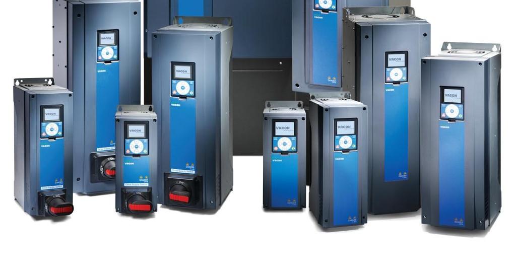
Vacon HVAC100 Commissioning Guide
|
|
|
- Shanon Austin
- 5 years ago
- Views:
Transcription

1 Vacon HVAC100 Commissioning Guide
2 INDEX 1. Glossary of terms 2. Wiring diagrams 3. Set up procedures a. Motor settings input b. Low level start, analogue input speed reference in AUTO position. Low level start, preset speed reference in MANUAL position. c. Setting up fixed speed firemode d. True Running status in firemode (if required) i. Local lock is also in this set-up e. Setting up PID f. Setting up PID firemode ( stair pressurization fans) g. Factory reset GLOSSARY OF TERMS 1. Digital Inputs are expressed as : a. Digital Input 1 = DiginSlotA.1 b. Digital Input 2 = DiginSlotA.2 etc. c. Not using a digital input = DiginSlot0.1 d. Keeping a digital input on/hi = DiginSlot0.2,3 or higher 2. Wizard is a list of questions to help quicken the set up procedure. All wizards are found in the Quick set up menu (M1) 3. MANUAL and AUTO position refer to position of switch on the Mechanical switchboard. 4. Firemode Refers to the drive running in a fire situation inhibiting its faults and alarms. 5. Low level refers to a 24V digital input 6. High Level refers to a fieldbus input like BacNet or Modbus for example. 7. Parameter numbers can also be given as P3.1.x.x
3 Commissioning Auto/Manual set-up 1. Upon first power up you will see Select language and press OK 2. Press OK on yes to activate startup wizard 3. Answer the next 5 questions a. Application Fan or pump. This will change ramps times and starting and stopping automatically b. Motor name plate RPM c. Motor name plate current rating d. Minimum frequency if required e. Maximum frequency if required f. Press OK to enter the Quick Set up menu 4. In the Quick set up Menu, check that :
4 a. Motor voltage is as per motor name plate b. Motor cos Phi is correct if available c. Motor power(kw) is correct as per motor name plate d. Add a current limit - if required e. Check that your (A) reference is from AI1(analogue input1) or AI2(analogue input2) f. Add your required Manual position on the Mechanical switchboard speed required eg. 30Hz in the Preset freq 1 g. Check all other parameters inside Quick set-up menu are ok. Eg. Aceleration times, deceleration times and automatic reset function 5. Press the back button to return to the Main menu and arrow down to highlight PARAMETERS and press ok


5 6. Arrow down to find the I/O Config sub menu and press ok, press ok on Digital inputs also 7. Arrow down to Ctrl Signal 1 B and press ok to edit to DigIN SlotA.4


6 8. Press back once to return to Digital Inputs sub menu. Press the down arrow once to show I/O B Ctrl Force 9. Press Ok to edit to as above DigIN SlotA Arrow down to Run enable and edit to DiginSlotA.6. This sets up the control isolator and firestop 11. Press Back button 3 times to return to Main Menu, arrow to Monitor and press ok and press ok again on Multimonitor 12. All Multimonitor values can be customised to suit. Eg. Digital input status, Analogue input value, Motor power(kw)


7 c) Fixed speed Firemode set-up (if required) 1. Press the back button till the Quick set-up menu is shown 2. Arrow down to find the firemode wizard, Press OK 3. Press ok to activate and start the wizard 4. After reading some text, the drive will ask for the speed reference. Eg. Dedicated firemode speed = Firemode Freq. 5. If Firemode Freq was chosen the next question will ask for that speed 6. The next question will ask; what type of input starts the drive If its normally open choose Close Contact. If its normally closed choose Open Contact.
8 7. After choosing the type of input, the drive will ask on what input activates/starts the firemode a. Remebering that all digital inputs start with DiginSlotA.?. The? being the digital input number 8. The next step asks if the drive will run in reverse during firemode eg. In normal mode it acts as a supply fan and in firemode acts as a exhaust fan. Remember DiginSlot0.1 means not used. 9. The last step has the firemode password which is given: Wizard is finished is displayed.
9 d) True running status (If required) 1. To set up a true running indication to fire panel in firemode only, the Relay output 1 function should be set to Run Indication 2. Also change parameter P to be a % of the motor nominal current which was entered in the Quick setup menu **In normal operation the relay will close via a run signal (not current dependant). In firemode operation the relay will only close if current is above % of motor nominal current
 Setting up PID Before starting you will need to know the")
10 i. Local lock function 1. Go to Main Menu > Parameters > Appl. Settings > FunctButtonConfig and press OK. In this window as shown below you can choose whether to show the local/remote as an option by unticking by pressing the right arrow e) Setting up PID Before starting you will need to know the transducer range eg pa, 0-250l/s. Also the transducer output(4-20ma or 0-10Vdc) 1. Press the back button till the Quick set-up menu is shown 2. Arrow down to find the PID Mini-wizard, Press OK 3. Press ok to activate and start the wizard
11 4. There is also help text to help with the setting up but the next question asks for the Process Units used eg. Pa, rpm, L/min, kpa etc. 5. This is where you will have to enter the minimum range of the tranducer, then the max as below 6. Next question asks for how many decimal places are to be displayed, followed then by what the feedback source is What analogue input is the transducer wired back to 7. The drive then asks for what analogue input range you are using

 Setting up Firemode PID **Run the PID Mini Wizard first as (e) above 1.")
12 8. Next question ask if the drive will be direct or reverse acting(reading description on drive may help here) 9. Setpoint selection is asked next. If the drives keypad is where it will be set please use Keypad SP Enter your setpoint here 11. Next question ask if you would like to use the drives sleep function which may be useful in certain applications that are at setpoint for most of the time. It acts as a energy saving feature too f) Setting up Firemode PID **Run the PID Mini Wizard first as (e) above 1. Press the back button till the Quick set-up menu is shown 2. Arrow down to find the firemode wizard, Press OK 3. Press ok to activate and start the wizard
13 4. After reading some text, the drive will ask for the speed reference. Choose PID Ref1 5. The next question will ask; what type of input starts the drive If its normally open choose Close Contact. If its normally closed choose Open Contact. 6. Next question will ask if drive is required to run in reverse direction in fire. If not leave as default of DiginSlot0.1. If it is to run in reverse direction to normal operation choose the same input as used in activating firemode 7. Firemode password of 1001 is given to finish the wizard


14 g) Factory Reset If there are any issues please return drive to factory settings by doing the following: 1. Return to the Main Menu to scroll down to find User Settings press Ok 2. Arrow down to Parameter Backup and press Ok, press Ok again on Restore Factory default and again to activate 3. Drive will display Vacon logo and return to language display
15
1. Vacon Startup Startup Wizard PID Mini-Wizard Multi-pump mini-wizard... 4
 vacon 100 hvac drives application manual vacon 0 INDEX Document ID: DPD00491E Order code: DOC-APP02456+DLUK Rev. E Version release date: 21..11 Corresponds to application package FW0065V012.vcx 1. Vacon
vacon 100 hvac ac drives application manual
 vacon 100 hvac ac drives application manual PREFACE VACON 3 PREFACE Document ID: DPD01696J1 Date: 20.11.2015 Software version: FW0065V030 ABOUT THIS MANUAL This manual is copyright of Vacon Plc. All Rights
FREQUENCY CONVERTER FC101 (QUICK GUIDE)
") FREQUENCY CONVERTER FC101 (QUICK GUIDE) INSTALLATION AND MAINTENANCE Content Page Safety instructions 2 IT system 3x230VAC 2 Connections 3 Control unit (LCP) 4 Manual operation 4 Reverse the direction
FREQUENCY CONVERTER FC101 (QUICK GUIDE) INSTALLATION AND MAINTENANCE Content Page Safety instructions 2 IT system 3x230VAC 2 Connections 3 Control unit (LCP) 4 Manual operation 4 Reverse the direction
FREQUENCY CONVERTER FC102 (QUICK GUIDE)
") FREQUENCY CONVERTER FC102 (QUICK GUIDE) INSTALLATION AND MAINTENANCE Content Page Safety instructions 2 IT system 3x230VAC 2 Connections 3 Control unit (LCP) 4 Manual operation 4 Reverse the direction
FREQUENCY CONVERTER FC102 (QUICK GUIDE) INSTALLATION AND MAINTENANCE Content Page Safety instructions 2 IT system 3x230VAC 2 Connections 3 Control unit (LCP) 4 Manual operation 4 Reverse the direction
Optidrive Applications Support Library
 Optidrive Applications Support Library Application Note Title AN-ODV-3-038 Related Products Optidrive Eco Overview Level 3 Modbus RTU Control and Register Mapping 1 Fundamental - No previous experience
PROGRAMMING MANUAL IM262R00. AQUAVAR Intelligent Pump Controller START-UP GENIE PROGRAMMING MANUAL
 PROGRAMMING MANUAL IM262R00 AQUAVAR Intelligent Pump Controller START-UP GENIE PROGRAMMING MANUAL TABLE OF CONTENTS Introduction 3 Chapter 1: Motor 4 Chapter 2: Application 5 2.1. Single Pump 5 2.2. Constant
Optidrive VTC Modbus RTU Register Map
 Application Note AN-VTC- 39 Optidrive VTC Modbus RTU Register Map Author: Ning Xu, Invertek Drives Ltd Revision: 2.21 6 September 2006 General This document details the Modbus RTU memory mapping implemented
Firmware Manual - EC Series Drives
 1 Firmware Manual - EC Series Drives Doc Ver 1.01 Firmware ver: EC series drives For installation details refer to Hardware Manual Safety: Read safety instruction in hardware manual before installation
E2 Modbus RTU Register Map Revision History Version Comments Author Date 1.02 Previous version PAE 11/06/ Revised to new format PAE 09/03/09
 Application Note Title AN-ODE-01 E2 Modbus RTU Register Map Revision History Version Comments Author Date 1.02 Previous version PAE 11/06/08 1.03 Revised to new format PAE 09/03/09 General This document
MOTOR STARTERS & VARIABLE SPEED DRIVES Variable speed drives
 C2000 VFD-CP Series AC Drive Motor power up to 400kW 3ph HVAC drive for variable torque loads Fire mode and bypass functions Sensorless vector control Features for building automation applications including
Basic Drive Programming PowerFlex 755 Basic Start Up
 Basic Drive Programming PowerFlex 755 Basic Start Up PowerFlex 755 Basic Start Up for Speed Controlled Applications Contents Before you begin... 4 Tools... 4 About this lab... 4 About the Demo... 4 Lab
Status line The top line of the LCD display shows the basic status information of the drive.
 Control panels 91 Status line The top line of the LCD display shows the basic status information of the drive. LOC 49.1Hz LOC MAIN MENU 1 No. Field Alternatives Significance 1 Control location LOC Drive
Baltimore Aircoil Company
 Baltimore Aircoil Company VFD Startup Guide TABLE OF CONTENTS: A. Verifying Power and Control Wiring...1 B. Setting the VFD Parameters...2 C. Reentering Startup Wizard After Initial Setup...5 D. Starting
SED2 Variable Frequency Drives
 SED2 Variable Frequency Drives Startup Procedure and Checklist Document No. 155-718 Table of Contents Prerequisites...1 Preparing for SED2 VFD Startup...1 HVAC Startup Procedure for SED2 with Bypass Option...4
P9 ASD Simple Start Guide
 P9 ASD Simple Start Guide Document Number: 64056-002 Date: June, 2011 P9 ASD Simple Start Guide P9 Programming Using the EOI The operating parameters displayed on the LCD screen may be selected, viewed,
3GV M Modbus RTU Register Map
 Application Note AN-ODP- 38 3GV M Modbus RTU Register Map Author: Ning Xu, Invertek Drives Ltd Revision: 2.21 15 June 2007 General This document details the Modbus RTU memory mapping implemented in Optidrive
E2 Modbus RTU Register Map
 Application Note AN ODE 01 E2 Modbus RTU Register Map Author: Peter Evans, Invertek Drives Ltd Revision: 1.02 11 June 2008 Software Version: 1.02 General This document details the Modbus RTU memory mapping
Basic control panel. Features. Control panels 75
 Control panels 75 Basic control panel Features The basic control panel features: numeric control panel with an LCD display copy function parameters can be copied to the control panel memory for later transfer
Metasys N2 Instruction Manual VLT Adjustable Frequency Drive. 12/ Revision B
 Metasys N2 Instruction Manual VLT 6000 Adjustable Frequency Drive 12/99-6110-00 Revision B 2 Table of Contents Overview Page Introduction... 5 About this Manual... 5 References... 5 Instructions Abbreviations
vacon nx ac drives brake chopper unit (bcu) application user s manual
 application user s manual") vacon nx ac drives brake chopper unit (bcu) application user s manual 2 vacon Introduction Vacon Brake Chopper Unit application INDEX Document code: DPD01565A Software code: ABFIFF01V113 Date: 27.3.2014
vacon nx ac drives brake chopper unit (bcu) application user s manual 2 vacon Introduction Vacon Brake Chopper Unit application INDEX Document code: DPD01565A Software code: ABFIFF01V113 Date: 27.3.2014
Technical Bulletin (TB-0040)
") Overview Technical Bulletin (TB-0040) Frequency Inverter Controller Install & Setup Version 6; April 2017 This document provides guidelines and information useful to a system manufacturer (OEM), installing
Overview Technical Bulletin (TB-0040) Frequency Inverter Controller Install & Setup Version 6; April 2017 This document provides guidelines and information useful to a system manufacturer (OEM), installing
Quick Start Guide Cutler-Hammer SVX9000 Drives from Eaton Corporation CONTENT STEP 1 Keypad Operation Overview STEP 2 Standard Wiring Diagrams and
 Quick Start Guide Cutler-Hammer SVX9000 Drives from Eaton Corporation CONTENT STEP 1 Keypad Operation Overview STEP 2 Standard Wiring Diagrams and Connections STEP 3 Start-Up Wizard STEP 4 Operating and
Q9 ASD LOW VOLTAGE DRIVE
 ASD LOW VOLTAGE DRIVE HVAC-MINDED, SYSTEM FRIENDLY RELIABLE Toshiba has manufactured pulse-width modulated drives since 1981 and is one of the few companies that manufactures both motors and drives in
ACS850 User s Guide ACS850 Control Panel
 ACS850 User s Guide ACS850 Control Panel ACS850 Control Panel User s Guide 3AUA0000050277 Rev A EN EFFECTIVE: 02.01.2009 2009 ABB Oy. All Rights Reserved. 5 Table of contents Table of contents About the
SMVector IP31 frequency inverter
 SMVector IP31 frequency inverter Flexible, simple, economical SMVector IP31 Simple Vector Control 2 Simplicity By making Lenze products easy to install, program and commission, we can provide the ideal
lnvertek Drives.com ct,ve ELECTRICAL SUPPLIERS LTD
 lnvertek Drives.com ft ct,ve ELECTRICAL SUPPLIERS LTD OptidriveE2 Technical Product Guide 1.1 OVERVIEW Range IP20 IP66X (NON SWITCHED) IP66Y (SWITCHED) Supply Voltage Range Power Range 110 115 + / 10%
INSTRUCTION MANUAL FOR GUARDIAN INFINITY SIM PROGRAM
 INSTRUCTION MANUAL FOR GUARDIAN INFINITY SIM PROGRAM Model: INF Firmware 60.xxx Date: July 16, 2008 Page 0 of 29 INDEX 1- INFSIM OVERVIEW:...3 1.1- STARTING THE SOFTWARE:...3 1.2- ESTABLISHING COMMUNICATIONS:...3
FAIRCHILD MODEL T1750 SERIES ELECTRO-PNEUMATIC TRANSDUCERS (Analog Output) Operation and Maintenance Instructions Software Version 3.45 and 3.
 Operation and Maintenance Instructions Software Version 3.45 and 3.") FAIRCHILD MODEL T1750 SERIES ELECTRO-PNEUMATIC TRANSDUCERS (Analog Output) Operation and Maintenance Instructions Software Version 3.45 and 3.46 Figure 1. Model T1750 Keypad SPECIFICATIONS Figure 2. Model
FAIRCHILD MODEL T1750 SERIES ELECTRO-PNEUMATIC TRANSDUCERS (Analog Output) Operation and Maintenance Instructions Software Version 3.45 and 3.46 Figure 1. Model T1750 Keypad SPECIFICATIONS Figure 2. Model
ETM MD100 Drive System 1/2HP (370W) User Manual. Table of Contents. Drive Features
 User Manual. Table of Contents. Drive Features") Table of Contents Drive Features... 1 Drive Specifications... 2 Certifications... 3 Installation - Drive Dimensions... 3 Motor Dimensions (mm)... 4 Drive Mounting... 4 Wiring... 5 I/O Terminals... 9 Menu...
Table of Contents Drive Features... 1 Drive Specifications... 2 Certifications... 3 Installation - Drive Dimensions... 3 Motor Dimensions (mm)... 4 Drive Mounting... 4 Wiring... 5 I/O Terminals... 9 Menu...
Installation and service manual. Accessories control equipment. Fan Inverter. Original instruction manual EN INSTRUCTION MANUAL (02)
") Installation and service manual ccessories control equipment Fan Inverter Original instruction manual EN INSTRUCTION MNUL 44837(0) Fan Inverter EN English Installation and Service manual Table of contents
Installation and service manual ccessories control equipment Fan Inverter Original instruction manual EN INSTRUCTION MNUL 44837(0) Fan Inverter EN English Installation and Service manual Table of contents
Optidrive Applications Support Library
 Optidrive Applications Support Library Application Note Title AN-ODE-3-038 Related Products Optidrive E3 Overview Level 3 Modbus RTU Control and Register Mapping 1 Fundamental - No previous experience
DVFP Series Variable Frequency Drive - Product Manual. pg. 1
 pg. 1 Set Up Instructions for DVFP Inspect the packaging of the equipment to confirm that nothing was damaged during shipping. Remove the system from the packaging. Make sure everything is included and
FlexPak 3000 Drive Operator Interface Module (OIM) User s Guide
 User s Guide") FlexPak 3000 Drive Operator Interface Module (OIM) User s Guide Instruction Manual D2-3344 The information in this manual is subject to change without notice. Throughout this manual, the following notes
FlexPak 3000 Drive Operator Interface Module (OIM) User s Guide Instruction Manual D2-3344 The information in this manual is subject to change without notice. Throughout this manual, the following notes
TR150 DRIVE STANDARD FEATURES
 TR150 DRIVE STANDARD FEATURES The TR150 Drive The TR150 Drive Series is a microprocessor-based, high frequency IGBT-based, PWM AC drive with control functions and software designed solely for the unique
MC Series Drives. Flexible, simple, rugged, robust!
 Drives Flexible, simple, rugged, robust! Our promise Commitment to Price Leadership Price leadership is serious business. It takes continuous life cycle management to make price leadership a sustainable
ADJUSTABLE SPEED DRIVES. Q9 Series
 ADJUSTABLE SPEED DRIVES Q9 Series Reliable & Configurable Reliable Toshiba has manufactured pulse-width modulated drives since 1981 and is one of the few companies that manufactures both motors and drives
Digistart. Soft starters for 3 phase induction motors 7.5 to 800kW (18 to 1600A) 200V, 400V, 575V, 690V
 200V, 400V, 575V, 690V") Digistart Soft starters for 3 phase induction motors 7.5 to 800kW (18 to 1600A) 200V, 400V, 575V, 690V Digistart Digistart is Control Techniques flexible soft starter range for motor control and protection
Digistart Soft starters for 3 phase induction motors 7.5 to 800kW (18 to 1600A) 200V, 400V, 575V, 690V Digistart Digistart is Control Techniques flexible soft starter range for motor control and protection
Quick Start Guide For GVX9000 AF Drives
 Quick Start Guide For GVX9000 AF Drives June 2006 New Information 5011646300 00GQ MN04000002E June 2006 Step 1 Wiring Hazardous High Voltage HIGH VOLTAGE! Motor control equipment and electronic controllers
UDC 1000 and UDC 1500 MICRO-PRO SERIES UNIVERSAL DIGITAL CONTROLLERS
 UDC 1000 and UDC 1500 MICRO-PRO SERIES UNIVERSAL DIGITAL CONTROLLERS EN0I-6041 12/99 PRODUCT SPECIFICATION SHEET OVERVIEW The UDC 1000 and UDC 1500 are microprocessor-based 1/16 DIN and 1/8 DIN controllers
1336-Series Drives to PowerFlex 750-Series Drives
 1336-Series Drives to PowerFlex 750-Series Drives 1336Plus 1336PlusII 1336Impact POWERFLEX 750 SERIES POWER CONNECTIONS TB1 ON 1336PLUS TB2 ANALOG SIGNALS AND RELAY FEEDBACK TB3 DIGITAL INPUTS FOR 1336
FLÄKTGROUP OFFERS A WIDE RANGE OF PER- MANENT MAGNET MOTORS (PM) AND FREQUENCY CONVERTERS FOR PLUG FANS. POWER RANGE IS FROM 0,8 KW TO 15 KW.
 AND FREQUENCY CONVERTERS FOR PLUG FANS. POWER RANGE IS FROM 0,8 KW TO 15 KW.") CENTRIFLOW PUR 3D (A, PLUG B, C, D) FAN GMPM FC101 AND SLIDE IN FREQUENCY ROTOR CASSETTE CONVERTER QUICK GUIDE FLÄKTGROUP OFFERS A WIDE RANGE OF PER- MANENT MAGNET MOTORS (PM) AND FREQUENCY CONVERTERS
CENTRIFLOW PUR 3D (A, PLUG B, C, D) FAN GMPM FC101 AND SLIDE IN FREQUENCY ROTOR CASSETTE CONVERTER QUICK GUIDE FLÄKTGROUP OFFERS A WIDE RANGE OF PER- MANENT MAGNET MOTORS (PM) AND FREQUENCY CONVERTERS
TECO L510 Inverter. Quick Start Guide. Step 1. Supply & Motor connection
 Quick Start Guide TECO L510 Inverter This guide is to assist you in installing and running the inverter and verify that it is functioning correctly for it s main and basic features. For detailed information
MAKING MODERN LIVING POSSIBLE. Instruction VLT HVAC Basic Drive Cascade Controller
 MAKING MODERN LIVING POSSIBLE Instruction VLT HVAC Basic Drive Cascade Controller 1.1 Cascade Controller Constant Speed Pumps (2) Variable Speed Pumps (1) Motor starter Illustration 1.1 Cascade Controller
Genset control and protection with safety system
 APPLICATION NOTES Generator Protection Unit, GPU-3 APPLICATION NOTES Genset control and protection with safety system Application description Functional description Wiring I/O lists Basic setup Flowcharts
Parallel SelfSensing Modulating Pump Controller
 Parallel SelfSensing Modulating Pump Controller Installation, Operation, and Maintenance Manual 302-380 SUPERSEDES: New EFFECTIVE: November 15, 2016 Plant ID: 001-0000 Table of Contents Connecting Controler...
Built-in features Built-in simplicity Built for fans & pumps
 GE Built-in features Built-in simplicity Built for fans & pumps AF-600 FP Fan & Pump Drives imagination at work Built for variable torque Specifically designed for fan and pump applications, the AF-600
PowerFlex 400 AC Drive Guide Specification
 PowerFlex 400 AC Drive Guide Specification Adjustable Frequency Drives with Bypass 3.0 50HP @ 208V AC 3.0 350HP @ 480V AC PART 1 GENERAL 1.01 Quality Assurance A. The manufacturer shall have minimum 5
TR200 DRIVE STANDARD FEATURES
 TR200 DRIVE STANDARD FEATURES The TR200 Trane Drive The TR200 Drive Series is a microprocessorbased, high frequency IGBT-based, PWM AC drive with control functions and software designed solely for the
Control system for rotary heat exchanger EQRB, L=3,4
 Installation instructions, drive system EQRB, L=3.4 sizes 005-072 General description A speed controlled drive system specifically adapted to drive rotary heat exchangers. No tuning is necessary. All control
SINAMICS IOP. Intelligent Operator Panel. Operating Instructions February 2009 SINAMICS
 SINAMICS IOP Intelligent Operator Panel Operating Instructions February 2009 SINAMICS Safety notes 1 Overview 2 SINAMICS SINAMICS Operating Instructions Installation 3 Wizards 4 Control 5 Menu 6 Options
AC Variable Speed Drive 0.75kW 250kW / 1HP 350HP Volt 1 & 3 Phase. Advanced User Guide Revision 1.10
 AC Variable Speed Drive 0.75kW 250kW / 1HP 350HP 200 480 Volt 1 & 3 Phase Advanced User Guide Revision 1.10 Optidrive P2 Parameter Set Overview 1 This Document is for use with version 1.20 Firmware. Advanced
- SELF-TUNING PID ALGORITHM - INTUITIVE COLOR DISPLAY WITH TEXT MESSAGING - UNIVERSAL PROCESS AND TC/RTD INPUTS - MULTI- FUNCTION RAMP- DWELL/PROCESS
 ELK. ETK COMPACT BASIC CONTROL - SELF-TUNING PID ALGORITHM - INTUITIVE COLOR DISPLAY WITH TEXT MESSAGING - UNIVERSAL PROCESS AND TC/RTD INPUTS - MULTI- FUNCTION RAMP- DWELL/PROCESS TIMER - SOFT START OUTPUT
Time Mark Corporation Model 42A Pump Controller User s Guide
 Time Mark Corporation Model 42A Pump Controller User s Guide Graphic display User friendly Expandable Communications capable 2009 Time Mark Corporation. All rights reserved. Made in the U.S.A. Time Mark
DriveWare. User s Guide DriveConfig
 DriveWare User s Guide DriveConfig DriveConfig User s Guide 3AFE68910897 Rev B EN EFFECTIVE: 1.2.2008 2008 ABB Oy. All rights reserved. 5 Table of contents Table of contents...5 Introduction to the manual...7
SR489 SR489. Generator Management Relay. Economical protection, metering, and monitoring functions for small and medium sized generators.
 SR489 Generator Management Relay Economical protection, metering, and monitoring functions for small and medium sized generators. 1 Product Highlights Inputs / Outputs Generator Protection Power Metering
Power Connections: Basic Wiring:
 Power Connections: The CFW10 Quick Start Guide is a supplement to help get the CFW10 started quickly using the most common installation and configuration options. This CFW10 Quick Start Guide is not meant
Peristaltic Cased Tube Pump
 Peristaltic Cased Tube Pump Selectable Output Control Functionality and Setup Version 1.0v-11/2016 Print-No. 01 Table of Contents 1. Introduction 2. Powering the Input/Output Port 2.1 Wiring for Local
PowerXL DG1 Redundant Drive Application
 pplication Note P040112EN PowerXL DG1 Redundant Drive pplication Introduction The Power XL DG1 is capable of operating a redundant drive scheme when using the internal PID controller in the drive. This
Quick Start Guide. PowerXL DG1 Series VFD
 PowerXL DG1 Series VFD Effective November 2017 Supersedes March 2014 Quick Start Guide Go to Eaton.com/DG1 Documents Tab: User manuals for DG1 Software Tab: To download Power Xpert incontrol and software
Tstat8. Bacnet Thermostat
 Tstat8 Bacnet Thermostat This full-featured thermostat is designed for cooling and heating systems in residential and commercial buildings. The thermostat can be configured for use with air handlers, fan
vacon nx user manual basic i/o boards expander i/o boards adapter i/o boards ac drives
 vacon nx ac drives basic i/o boards expander i/o boards adapter i/o boards user manual vacon 2 General information. GENERAL INFORMATION VACON NX range embodies a wide selection of expander and adapter
TABLE OF CONTENTS INTRODUCTION. 3. Analog Input Analog Output Digital Input Digital Output OPERATIONAL DESCRIPITON.. 7 PROGRAMMING AND INITIAL SETUP.
 DIVERSIFIED HEAT TRANSFER SERIES 700 STEAM GENERATOR CONTROLLER INSTRUCTION MANUAL VISIT OUR WEBSITE AT SIGMACONTROLS.COM SERIES 700 DHT STEAM GENERATOR MANUAL 042514 2 TABLE OF CONTENTS INTRODUCTION.
Powered to Perform. Everyday Reliability. Exceptional Value. Expertise and Support
 A decentralized solution. Many drive applications utilize control panels with complex wiring taking up large amounts of space. These control panels are often mounted away from the application requiring
Automatic Genset Controller, AGC-3 What's in the delivery Getting started The first steps Using the AGC
 QUICK START GUIDE Automatic Genset Controller, AGC-3 What's in the delivery Getting started The first steps Using the AGC DEIF A/S Frisenborgvej 33 DK-7800 Skive Tel.: +45 9614 9614 Fax: +45 9614 9615
Automatic Genset Controller, AGC-4 What s in the delivery? Getting started The first steps Using the AGC
 QUICK START GUIDE Automatic Genset Controller, AGC-4 What s in the delivery? Getting started The first steps Using the AGC DEIF A/S Frisenborgvej 33 DK-7800 Skive Tel.: +45 9614 9614 Fax: +45 9614 9615
Altivar 21 Programming and Operation Guide
 Altivar 21 Programming and Operation Guide Instruction Bulletin 372-451-63 Retain for future use. 372-451-63 Altivar 21 Programming and Operation Guide 3/27 Table of Contents Hazard Categories and Special
BACnet MS/TP Interface User s Guide
 PoolPak MPK with CommandPak Control System CPCS BACnet MS/TP Interface User s Guide DOCUMENT #: SVW07-BACNET-MSTP-20171020 UPDATED: OCTOBER 2017 INTRODUCTION PoolPak dehumidifiers equipped with an CommandPak
AF-600 FP AC Drive AC Adjustable Frequency Drive Guide-Form Specification
 AF-600 FP AC Drive AC Adjustable Frequency Drive Guide-Form Specification Contents 1.0 General Information 2.0 Operating Conditions 3.0 Standards 4.0 Input Power Section 5.0 Output Power Section 6.0 Drive
AC Variable Speed Drive 0.75kW 250kW / 1HP 350HP Volt 1 & 3 Phase. Advanced User Guide Revision 2.00
 AC Variable Speed Drive 0.75kW 250kW / 1HP 350HP 200 480 Volt 1 & 3 Phase Advanced User Guide Revision 2.00 Optidrive P2 Advanced User Guide Rev 2.00 Optidrive P2 Parameter Set Overview 1 This Document
FTA3100 Series Setup and Operating Instructions
 FTA3100 Series Setup and Operating Instructions FTA3100 Series VFD Controllers for Variable Speed Pressure Limiting Mark II Mark II XG Instruction Manual NS3100-50M Addendum to Mark II NS1000 Series Instruction
Standard Options. Model 4100 Position Indicating Meter. Three Phase Motor Control. Positran Transmitter
 Standard Options Model 4100 Position Indicating Meter A percent-of-full-travel meter is supplied with a trim potentiometer resistor, terminal block and connectors. A potentiometer is required in the actuator
Power 004=0.4kW 015=1.5kW. Delta Variable Frequency Drive
 Type number key VFD 007 L 21 A Version number A= filter, NPN inputs B=Built-in filter, NPN inputs D= filter, PNP inputs E=Built-in filter, PNP inputs Input voltage 11=115VAC 21=230VAC 1φ 23=230VAC 3φ VFD-L
Sinamics G120P. Training Booklet. Answers for infrastructure and cities.
 Sinamics G120P Training Booklet Answers for infrastructure and cities. System configuration required for commissioning STARTER software Processor with min. 1 GHz (dual core recommended) 1024 MB RAM (2048
MAKING MODERN LIVING POSSIBLE. ADAP-KOOL Drive. A New Drive for Energy Efficiency AKD 102 REFRIGERATION & AIR CONDITIONING DIVISION
 MAKING MODERN LIVING POSSIBLE REFRIGERATION & AIR CONDITIONING DIVISION ADAP-KOOL Drive A New Drive for Energy Efficiency AKD 102 2 The AKD 102 comes with a common user interface and covers power ratings
SENSORLESS VECTOR CONTROL
 D SERIES EM16 STANDARD DRIVE SENSORLESS VECTOR CONTROL EM16 STANDARD DRIVE SENSORLESS VECTOR CONTROL 1 2 SERIES 1 2 page 4 page 6 Introduction Fields of application 3 page 7 4 page 8 Designation Product
Installation Instructions Part No: 38AP , 38AP , and 38AP
 09DPS08-0,09DPM05-0 MOTORMASTER V Electronic Control Low Ambient Operation Accessory Installation Instructions Part No: 8AP-900---09, 8AP-900---00, and 8AP-900---0 CONTENTS Page GENERAL........................................
Quick Start Guide. Variable Speed Drive. Part Number: Issue: 3
 EVC Series Quick Start Guide English Issue 3.book Page 1 Friday, March 11, 2016 1:38 PM Quick Start Guide Variable Speed Drive Part Number: 0478-0335-03 Issue: 3 Original Instructions For the purposes
Contents. Temperature & Process Measurement Indicators Setup Guide
 Contents Introduction... 2 Installation... 3 Connections... 5 Connecting the Sensor... 6 Powering the Instrument... 7 Operator Functions... 8 The Setup Menus... 9 Configuration Menu Map... 12 Menu Options...
VARMECA 20. Variable speed motors and geared motors. Parameter setting manual. This manual is to be given to. the end user CDC -VMA 20
 CDC -VMA 20 en P01 FMIN. FREQUENCE MIN. MIN. FREQUENCY MIN. FREQUENZ P02 REF 0V 4MA ETALONNAGE CONSIGNE MIN. MIN. REF. SCALING ABGLEICH SOLLWERT MIN. P0 F MAX. FREQUENCE MAX. MAX. FREQUENCY MAX. FREQUENZ
DC1 Series 1 Hour Product Overview Eaton Corporation. All rights reserved.
 DC1 Series 1 Hour Product Overview Agenda PowerXL Family DC1 product overview Applications drivesconnect DC1 demo Programming Sales fuel Tools and resources Support and services 2 Eaton Product Offering
HVAC Products. Introducing the SED2 Variable Frequency Drives
 HVAC Products Introducing the SED2 Variable Frequency Drives Designed Specifically for HVAC Applications From a global leader in drives technology and innovation, now comes a drive specifically configured
From lab to production, providing a window into the process. Dynisco's ATC990 and UPR900 Applications and Setup
 From lab to production, providing a window into the process Dynisco's ATC990 and UPR900 Applications and Setup Introduction UPR900 Indicator Is ¼ Din (96x96mm) size, 117mm depth behind the panel. It has
1.1.1 Software Version Introduction About this Manual References 2
 Contents Contents 1 Overview 2 1.1.1 Software Version 2 1.1.2 Introduction 2 1.1.3 About this Manual 2 1.1.4 References 2 2 Instructions 3 2.1.1 Abbreviations and Definitions 3 2.1.2 Network Connection
QUICK START GUIDE Paralleling and Protection Unit PPU 300
 QUICK START GUIDE Paralleling and Protection Unit PPU 300 DEIF A/S Frisenborgvej 33 DK-7800 Skive Tel.: +45 9614 9614 Fax: +45 9614 9615 info@deif.com www.deif.com Document no.: 4189341107B 1. Introduction
Taco System Logic (TSL)
") Taco System Logic (TSL) 302-370 Installation, Operation, and Maintenance Manual SUPERSEDES: June 27, 2014 EFFECTIVE: December 21, 2015 Table of Contents 1 ELECTRICAL CONNECTIONS................. 2 1.1
Taco System Logic (TSL) 302-370 Installation, Operation, and Maintenance Manual SUPERSEDES: June 27, 2014 EFFECTIVE: December 21, 2015 Table of Contents 1 ELECTRICAL CONNECTIONS................. 2 1.1
QUICK REFERENCE GUIDE
 acknowledges changed values, fault history, and is pressed to enter program resets starts the motor when the panel is the stops the motor when the panel is the - and I/O CONNECTIONS SCREEN DISPLAYS QUICK
PART 1: GENERAL PART 2: PRODUCT. Effective: 12/29/10 Page 1 of 6 FECA-TE-104D
 Specification Number: 23 09 33 Product Name: FRENIC-Eco AC Drives for Variable Torque Fan & Pump Applications (1-125Hp at 208/230V and 1-900Hp at 460V) PART 1: GENERAL 1.01 SUMMARY A. This specification
SD250 VARIABLE SPEED DRIVE
 VARIABLE SPEED DRIVE SD250 Ranging from 0.4kW to 22kW, 200-230V and 380-480 Vac Easy programming and monitoring through cursors and digital display, removable up to 5m Wide range of accessories: RFI filter,
Automatic Genset Controller, AGC-4 What s in the delivery? Getting started The first steps Using the AGC
 QUICK START GUIDE Automatic Genset Controller, AGC-4 What s in the delivery? Getting started The first steps Using the AGC DEIF A/S Frisenborgvej 33 DK-7800 Skive Tel.: +45 9614 9614 Fax: +45 9614 9615
Safety Instructions 1-1 Avoid unintended Start General Description 2-2
 Contents Contents 1 Safety and precautions 1-1 Safety Instructions 1-1 Avoid unintended Start. 1-1 2 Introduction 2-1 General Description 2-2 3 Supported Configuration 3-1 Introduction 3-1 Fixed-speed
ADXL Series SIMPLE, EFFICIENT AND SAFE MOTOR CONTROL
 SOFT STARTERS ADXL Series SIMPLE, EFFICIENT AND SAFE MOTOR CONTROL Simplicity The ADXL series of soft starters is equipped with a backlit LCD icon display and NFC connectivity for quick and easy configuration,
pco 3 Controller User Manual ASPX Digital Scroll, Air Packaged Chiller For Version MCDSV_A02
 pco 3 Controller User Manual ASPX Digital Scroll, Air Packaged Chiller For Version MCDSV_A02 pco 3 Controller User Manual Introduction The Airstack Chiller is a modular air-cooled chiller composed of
CATALOG SELECTION / PRODUCT SELECTION
 catalog selection / product selection Motor Control Drives CATALOG SELECTION / PRODUCT SELECTION M-Max Machinery Drive Catalog Numbering System MMX AA D F - 0 Base Catalog Number Option Drives Phase =
MSC-3. Instruction Manual
 MSC-3 Instruction Manual ZENER ZENER TECHNOLOGY AND QUALITY ASSURANCE Since 1976 Zener Electric has supplied many thousands of drives to industry. These drives have been installed into numerous applications
SUPPLEMENTAL MANUAL FACTORY-INSTALLED ABB VARIABLE FREQUENCY DRIVES (VFD) IN RENEWAIRE (ERV) VENTILATORS TABLE OF CONTENTS
 IN RENEWAIRE (ERV) VENTILATORS TABLE OF CONTENTS") SUPPLEMENTAL MANUAL FACTORY-INSTALLED ABB VARIABLE FREQUENCY DRIVES (VFD) IN RENEWAIRE (ERV) VENTILATORS MODEL SHOWN: ACS 0 TABLE OF CONTENTS VFD KEYPADS IN E-BOX Product info... Installation... -9 Operation...
SUPPLEMENTAL MANUAL FACTORY-INSTALLED ABB VARIABLE FREQUENCY DRIVES (VFD) IN RENEWAIRE (ERV) VENTILATORS MODEL SHOWN: ACS 0 TABLE OF CONTENTS VFD KEYPADS IN E-BOX Product info... Installation... -9 Operation...
Intelligent Operator Panel (IOP) SINAMICS. Intelligent Operator Panel (IOP) Safety notes 1. Overview 2. Installation 3. Wizards 4. Control 5.
 SINAMICS. Intelligent Operator Panel (IOP) Safety notes 1. Overview 2. Installation 3. Wizards 4. Control 5.") Safety notes 1 Overview 2 SINAMICS Operating Instructions Installation 3 Wizards 4 Control 5 Menu 6 Options 7 Technical data 8 Edition 08/2015, Firmware IOP V1.6.1 08/2015, FW V1.6.1 A5E00110011B AF Legal
Safety notes 1 Overview 2 SINAMICS Operating Instructions Installation 3 Wizards 4 Control 5 Menu 6 Options 7 Technical data 8 Edition 08/2015, Firmware IOP V1.6.1 08/2015, FW V1.6.1 A5E00110011B AF Legal
ACH400. User s Manual ACH 400 AC Drives for Speed Control of 50 to 100 Hp, 230 Volt and 60 to 400 Hp, 460 Volt AC Induction Motors
 ACH400 User s Manual ACH 400 AC Drives for Speed Control of 50 to 100 Hp, 230 Volt and 60 to 400 Hp, 460 Volt AC Induction Motors ABB Automation, Inc. ACH 400 AC Drives for Speed Control of AC Induction
Parameters MICROMASTER 420
 Parameters MICROMASTER 40 This Parameter List must only be used together with the Operating Instructions or the Reference Manual of the MICROMASTER 40. Especially pay attention to all the warnings and
SPX 1hr product overview Eaton Corporation. All rights reserved.
 SPX 1hr product overview 2012 Eaton Corporation. All rights reserved. Eaton Product Offering Machinery OEM Drives DE1, DC1, DE1, DA1, M-Max HVAC Drives H-Max 0.25HP 25HP 1HP 250HP General Purpose Industrial
CONTROLLER INSTALLATION OPERATION & QUICK START
 CONTROLLER INSTALLATION OPERATION & QUICK START Controller: 8403-066 ECU Series Controller Manual: 2100-559 Supersedes: NEW File: Tab 19 Date: 05-02-11 Page 1 of 6 TABLE OF CONTENTS Installation Note...