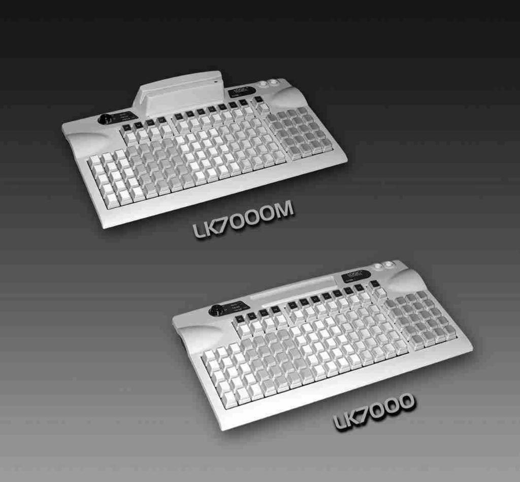
Model: LK7000. Programmable Matrix Keyboard. 119 Keys with Built-in Scanner and MSR USER MANUAL
|
|
|
- Mervin Hopkins
- 5 years ago
- Views:
Transcription
1 Model: LK7000 Programmable Matrix Keyboard 119 Keys with Built-in Scanner and MSR USER MANUAL
2 NOTICE The manufacturer of the POS programmable keyboard makes no representations or warranties, either expressed or implied, by or with respect to anything in this manual, and shall not be liable for any implied warranties of fitness for a particular purpose or for any indirect, special or consequential damages. Information in this document is subject to change without notice and does not represent a commitment on the part of the manufacturer. FCC NOTICE This device complies with Part 15 of FCC Rules. Operations is subject to the following two conditions: (1) this device may not cause harmful interference. and (2) this device must accept any interference received, including interference that may cause undesired operation. LOGIC CONTROLS, INC. 355 Denton Ave New Hyde Park, NY TEL: (516) FAX: (516) lci@logiccontrols.com i
3 TABLE OF CONTENTS FEATURES... 1 CARTON CONTENTS... 2 HARDWARE CONNECTIONS... 3 FUNCTIONAL TEST...4 UTILITY DISK CONTENTS...6 INSTALLING THE LK7000.EXE UTILITY PROGRAM... 7 STARTING THE LK7000.EXE PROGRAM... 7 PROGRAMMING THE LK7000 KEYBOARD...8 ADVANCED PROGRAMMING...10 SPECIAL FEATURES OF THE LK INTER-STRING DELAY...11 MULTI-LEVEL DEFINITION...12 SPECIAL CONFIGURATIONS...14 DATA TRANSFER MENU...16 SPECIFICATIONS...18 ADDENUM...19 ii
4 FEATURES Optional left or right laser bar code reader Optional credit card reader Contemporary design Fully programmable Matrix Layout Tactile mechanical key switches Keylock for multiple program layers Multiple shift layers True keyboard wedge function, operates with or without computer keyboard Up to 256 characters/key, include all function & control keys No programming accessory kit, TSR program, or battery required Available with RS232C output 1
5 CARTON CONTENTS LK Keyboard, Model LK Computer interface cable - RJ11 6-pin Male keyboard interface cable - PS/2 Male to AT Female 4. Utility software disk 5. Legend label sheet 6. User s manual 2
6 HARDWARE CONNECTIONS The LK7000 can be connected to an IBM101 PC, XT, AT or clone computer, PS/2 computer, or computer terminal. The following diagram shows how the keyboard connects to the computer and standard keyboard or other keyboard peripheral (magnetic stripe reader, scanner, etc.). To Peripheral To Computer Reserved for optional MSR NOTE: Before making any connections it is always advisable to turn off the computer. A. Connecting the LK7000 to an IBM101 PC, XT, AT, or clone computer s keyboard port: 1. Use the computer interface cable. Plug the AT or PS/2 Male connector plug into the compter. Connect the RJ11 connector into the To Computer connector on the LK Connect the keyboard interface cable to the standard keyboard. The PS/2 Female connector plugs into the PS/2 connector on the rear panel of the LK7000. The RJ11 connector plugs into the To Peripheral connector on the back of the LK
7 FUNCTIONAL TEST For testing purposes, your LK7000 keyboard was pre-programmed with a template called LK7000.TPL. The following simple steps will verify that the keyboard is in good working condition: 1. Follow the Hardware Connections procedure described earlier in this manual to connect the LK7000 to your computer. 2. Turn on your computer. 3. At the DOS prompt, press the upper left key of the keyboard. 4. The keyboard is working correctly when the words LOGIC CONTROLS PROGRAMMABLE KEYBOARD, MODEL LK7000" appears on the monitor. To verify if the other keys are working simply press each key and verify that the information displayed on the monitor matches the template shown at the end of this section. 4
8 5
9 UTILITY DISK CONTENTS All LK7000 keyboards come with a utility software disk. This disk contains several important files: LK7000.EXE - LK7000.TPL - Use this utility with or without the keyboard being attached. It is used to program the keyboard. For a complete description of how this program works see the section Programming the LK7000 keyboard. This template was pre-programmed into the keyboard and matches the legend shown on the previous page. If you have any questions on how to program a particular key you can refer back to this template to see how it was originally programmed. INSTALLING THE LK7000.EXE UTILITY PROGRAM The first step in using the LK7000.EXE utility program is to copy the program to your hard drive. 1. Insert the LK7000 utility software into drive A or B of the computer. 2. Type MD LK7000 at the C> prompt to make a directory named LK Type CD LK7000 to make the LK7000 directory active. 4. Type COPY A:*.* If the disk was inserted into drive A then all files will be copied into the hard drive s directory (LK7000). If drive B is used then you must type COPY B:*.* 6

10 STARTING THE LK7000.EXE PROGRAM This program can be used with or without the keyboard being attached to the computer. Note that the PC must be booted up in DOS before starting the program. It will not run properly under Windows DOS prompt. To start the program, type LK7000 at the LK7000 DOS prompt and press ENTER. When the program is up, it will automaticallly display the graphic graphics screen as below. 7
11 PROGRAMMING THE LK7000 KEYBOARD The following procedure will show you how to program your LK7000 with standard (keyboard) alphanumeric characters. The keyboard can be programmed with either ASCII or Scan code information. The default mode is the ASCII code mode. The following procedure assumes both a LK7000 keyboard and a 101 keyboard are attached. NOTE: To run this program you must exit windows completely. Do not shell out from Windows. 1. With the correct programming graphics present. Select the cell you want to program by using the arrow keys on the 101 keyboard. The Up and Down arrows will select the row while the Shift and either the Right or Left arrow key will select the column. 2. Enter your programming text via the 101 keyboard. Continue programming until all the keys are programmed. It is not necessary to program all the keys for the LK7000 to function properly. The maximum number of alphanumeric characters that can be programmed for any one key is 256. NOTE: The maximum number of alphanumeric characters that can be programmed per standard keyboard is DATA TRANSFER MENU Dos shell File list (*.tpl) Load file from disk Read from keyboard Save file to disk Write to keyboard Press ESC to Quit 3. Press F2 to call up the Data Transfer Menu. There will be several choices to choose from. 4. Type W to write the programmed data into the LK7000 s non volatile memory. A Writing Data screen will open showing the percentage of memory written. It will take approximately 7 seconds to copy the data into the keyboard. 8
12 5. Type S to save the programmed data into the LK7000 directory. You can select up to an 8 character name. It will be saved with a.tpl extension. 6. Press ESC to terminate the Data Transfer Menu. 7. Press F10 followed by Y to exit the utility program. 8. To verify that your program has been successfully installed, simply press any programmed key. The information stored in that key will appear on the monitor. 9. The next time you want to install the legend you just created simple press F2 to call up the Data Transfer Menu and then press L to open the Load window. 10. Enter the name of the file in the legend window with its proper extension (.TPL) and press ENTER. The legend will now show on your monitor. 9
13 ADVANCED PROGRAMMING The LK7000 POS keyboard can be programmed with all special control and function keys such as the Shift, Ctrl, Alt, F1 through F12, and the up/ down/left/right arrow keys. The procedure to program these special keys is shown below: 1. Start the LK7000 utility program. 2. Select the cell to be programmed. Press F8 to enter the scancode mode. The code type information changes from ASCII to SCAN. NOTE: The scan-code mode will only be active for this cell. You must select F8 for each cell you want to program with scan-code information. 3. Under the scan-code mode, each alphanumeric character is enclosed in parenthesis. For special function or control keys, press ESC (three vertical bars will be present) followed by the special function or control key you want to program. For example, to program the INS (insert) key, press ESC and then the INS key on the 101 keyboard. To program the ESC key, simply press the ESC key twice. Special function and control keys will not appear inside parenthesis. The three vertical bars will disappear once the special function key is depressed. 4. You may return to the start-up graphic screen (short menu) by pressing Ctrl-Alt-F4 again. NOTES: 1) Special function keys require ESC as the leading code. In the scan-code mode, you can view the symbol of the special key or the hex code equivalent of the special key. To view, simply press F7 to toggle between symbol and hex modes. 2) Once a special function key (shift, ctrl, alt, etc.) is programmed it may be necessary to un-select the function. To do so, press in sequence ESC, f (lower case F), 0 (zero), ESC, followed by the special function key (shift, ctrl alt, etc.) 3) Any given programmable location may be toggled between scan-code mode and ASCIIcode mode. Pressing the F8 key on the keyboard will change the cell s programming mode to scan-code mode. Pressing F9 on the keyboard will change the cell s programming mode to ASCII-code mode. Changing modes in a cell that has been previously programmed will erase all the information in that cell. 4) To enter hex scan-codes directly, press ESC followed by the 2-digit hex number. For example, to program the CTRL key press ESC followed by 1D. The LK7000 program will add the leading zero 10
14 SPECIAL FEATURES OF THE LK7000 Besides being able to program all the keys of an IBM101 keyboard, the LK7000 has also incorporated three state-of-the-art features which will add flexibility and functionality to the keyboard. INTER-STRING DELAY This feature allows for a time delay(s) to be installed after a character(s) has been inserted into a cell. To use this feature follow the steps below: 1. Enter the character(s) which will precede the delay. For example, ABC. 2. Depress and hold the ALT key while pressing the letter D. A time delay screen will open asking for the amount of delay you require (up to 240 seconds). Select the appropriate delay and press ENTER. A square pixel will appear on the programming line immediately following the last character typed. 3. Type the next character(s), DEF. You can use more than one delay per cell and each delay time can be different. 4. Save the template and then write the template to the keyboard. 5. Exit the LK7000 program by pressing F10 followed by the letter Y. 6. Press the location key where the time delay character has been stored. The monitor will display ABC immediately. After the delay time you entered for this key has expired, DEF will be displayed on the monitor and the cursor will be present at the prompt. 11
15 MULTI-LEVEL DEFINITION This feature can increase the apparent number of programmable keys by allowing you to program different levels into any cell. For every different level you program you must select another key to be a SHIFT LEVEL key. Programming is accomplished in the normal manner. After programming the base level a separator bar must be entered to separate the base level from the second level. You can program more than two levels per cell. For example, if you needed to program small coffee, medium coffee, and large coffee into one cell follow the procedure outlined below: 1. Select a blank cell and enter the most common coffee first (medium coffee). Mark the legend sheet for this cell COFFEE. 2. Enter the separator bar by depressing and holding the ALT key and pressing the letter S. A solid line will appear on the programming line immediately following the last character typed. 3. Enter the second level (small coffee) followed by another separator. 4. Enter the third level of information (large coffee). The entire programming line should look like the following: F5 MEDIUM COFFEE SMALL COFFEE LARGE COFFEE 5. Select a blank location to (F11) become the first level shift position. Mark the legend sheet for this location SMALL. 6. Change the programming mode of this cell to scan-code mode (F8). Depress and hold the ALT key while pressing the letter A. A triangle inside brackets (< >) will appear on the programming line. This key when depressed and held will activate all keys that have a second level. 7. Select another blank location (F12). This will become the second level shift position (will activate the third level of information). Mark the legend sheet for this position LARGE. 12
16 8. Change the programming mode of this cell to the scan-code mode (F8). Depress and hold the ALT key while depressing the letter A twice. Two triangles inside brackets will appear on the programming line. 9. To use this feature in your application is extremely simple. When medium coffee is desired just press the F5 key (the first level of information stored in cell F5 will be sent to the computer). When a small coffee is desired press and hold the F11 key while pressing the F5 key (the second level of information stored in cell F5 will be sent to the computer). When a large coffee is desired press and hold the F12 key while pressing the F5 key (the third level of information stored in cell F5 will be sent to the computer) NOTE: There is no preset limit to the number of levels that can be programmed into a keyboard. 13
17 SPECIAL CONFIGURATIONS The keyboard can be set up with many different programming options. To activate the configuration menu screen press F3. By depressing the highlighted letter in each option, the program will enable or disable that option. The default settings are shown in the graphic below. Send Break-codes for scan-codes Enable beep while a key pressed No beep if a key is undefined Translate to code-set #2 for AT Emulating XT keyboard always Use ALT+num to generate ASCII Enable Typematic for scan codes Enable Typematic for ASCII codes Emulating Link Terminal InterCharacter Delay (+/-): Enable RS232 Output Baud Rate: Parity: Length of Data: 2 Yes Yes Yes Yes No No No No No ms No 9600 NONE 8 -bits Press a High-light Letter to select Esc ==> Quit from this menu 14
18 DESCRIPTION OF SPECIAL CONFIGURATION MENU F3 Send Break-code for scan-codes - Enables or disables the transmission of break codes for each scan code programmed into the keyboard. Enable beep while a key pressed - Enables or disables the entire keyboard from beeping when any key is depressed. No beep if a key is undefined - If a key is not programmed it will not beep when depressed. Translate to code set #2 for AT - Enables or disables the output of the keyboard to be translated into AT scan code. Emulating XT keyboard always - Enables or disables the output of the keyboard to be translated into XT scan code. Use ALT +num to generate ASCII - Enables or disables the ability to use the ALT key along with the numeric keyboard to generate ASCII codes. Enable typematic for scan codes - Enables or disables keys programmed with scan code information to repeat the programmed characters as long as the key remains depressed. Enable typematic for ASCII codes - Enables or disables keys programmed with ASCII code information to repeat the programmed characters as long as the key remains depressed. Emulating Link Terminal - Enables or disables the keyboards ability to emulate a link terminal. Intercharacter Delay (+/-) - The time delay between characters can be adjusted from 1 millisecond to 266 milliseconds. This delay is set for all characters programmed into the keyboard. Do not confuse this feature with the inter-string delay feature. 15
19 DESCRIPTION OF SPECIAL CONFIGURATION MENU F3 (CONTINUED) Enable RS232 Output - Enables or disables the output of the keyboard to the RS232 port (DB9 connector). If this option is set to YES then the protocol settings must be set to mirror the application software. Baud Rate - This option selects 2400, 4800, 9600 and 19,200 baud rates. Parity - This option selects ODD, EVEN or NO parity. Length of data - This option selects either 7 or 8 data bits. DATA TRANSFER MENU Save COMPUTER'S RAM MEMORY Write COMPUTER'S HARD DISK Load Read LK7000 KEYBOARD 16
20 Dos shell File list (*.tpl) Load file from disk Read from keyboard Save file to disk Write to keyboard Press ESC to Quit The LK7000 keyboard, working in conjunction with the LK7000.EXE utility software, can perform the following powerful functions: * Save programmed data as a template file (.TPL) in both the keyboard and the hard drive of the computer. To save programmed data to the keyboard use the W (Write to keyboard) option of the Data Transfer Menu. To save programmed data to the hard drive use the S (Save file to disk) option of the Data Transfer Menu. * Load (L) a previously programmed template from the hard disk into the computer s volatile RAM memory. The same template can then be written (W) into the non-volatile memory of the keyboard. This process, as an example, allows a restaurant to change from a breakfast menu to a lunch menu within 7 seconds. * Enables the computer to read (R) a template stored in the LK7000. That template can then be saved (S) to the hard disk for future use. * Display a list of templates that have been stored onto the hard disk within the LK7000 directory. From the Data Transfer Menu select F for File List. The computer s monitor will display the list of.tpl files stored in the LK7000 directory. * Interruption of the programming process to shell out to DOS (D) to perform other operations. To return to the programming process type EXIT at the DOS prompt. NOTE: Never shell out of windows to work in this utility program. Boot up computer in DOS. 17
21 LK7000 PROGRAMMABLE KEYBOARD SPECIFICATIONS MECHANICAL Weight Basic Unit 2.5lbs. with MSR 2.7lbs. with Scanner 2.6lbs. Dimension (in inches) STD w/msr Width Depth Front Height Rear Height w/legs ext Keys Full travel mechanical Life cycle >10 million tactile cycles MSR 2 tracks standard Life Cycle 300,000 passes SCANNER Laser Class CDRH Class II MTBF 100,000 hours ELECTRICAL Input voltage (from computer) Current Basic Unit MSR Scanner Standby Scan Mode Surge +5VDC 25ma 50ma 15ua 100ma 130ma ENVIRONMENTAL Operating Temp 0 o C to +50 o C Storage Temp -20 o C to +60 o C Relative Humidity Operating 85% max. non-condensing INTERFACE Non-operating 90% max. non-condensing Vibration (10 to 55 Hz.) 4G's Shock 40G's Keyboard Wedge RS232C Standard Optional GENERAL INFORMATION Keyboard interface cable, utility software, and legend labels supplied. PROGRAMMING THE KEYBOARD 1.Use the utility software supplied to program up to 256 alphanumeric characters per key. Utility program will write to and read from computer disk memory. 2. Keyboard supports computer control keys (Shift, CTRL, ALT, F1 through F12) and all arrow keys). CONNECTOR PINOUTS J1 (PS/2F) to PS/2 Keyboard 1 Keyboard Data 2 No Connection 3 Ground 4 +5VDC 5 Clock 6 Shield J2 (RJ11F) to Computer 1 Clock 2 Data 3 No Connection 4 Ground 5 +5VDC 6 No Connection J3 (RJ45F) to MSR 1 RDP1 2 RCP1 3 CLS1 4 RDP2 5 RCP2 6 CLS2 7 +5VDC 8 Ground 6 4 J4 (DB9M) RS232C to Computer 1 DCD 2 Receive Data (from computer) 3 Transmit Data (to computer) 4 DTR 5 Ground DSR 7 RTS 8 CTS No connection Pins 1,4, and 6 are tied together internally Pins 7 and 8 are tied together internally J4 J1 J2 J3 18
22 ADDENDUM SCANNER POSITION The LK7000, a matrix programmable keyboard with built-in scanner, was designed with the end user in mind. The scanner can be factory installed on either side of the keyboard, giving the enduser the versatility required in todays applications. PITCH ANGLE To accomodate different customer installations the scanner s pitch angle can be adjusted via a lever on the bottom side of the keyboard. TO ACTIVATE THE SCANNER The top right key on the LK7000 has been hardwired to the scanner, and serves as the scanner s trigger. This key is dedicated to activating the scanner. The scanner could also be set in an always on state by changing the default settings on the scanner. SYMBOLOGIES The default parameters of the scanner includes the reading of many different symbologies
Model: KB1700. Programmable Keypad. 17 Programmable Keys USER MANUAL
 Model: KB1700 Programmable Keypad 17 Programmable Keys USER MANUAL NOTICE The manufacturer of the POS programmable keypad makes no representations or warranties, either expressed or implied, by or with
Models: TD3000 Series. Table Displays. 2 by 20 character display USER MANUAL
 Models: TD3000 Series Table Displays 2 by 20 character display USER MANUAL i NOTICE The manufacturer of the POS table display makes no representations or warranties, either expressed or implied, by or
Models: LD9000 Series. Customer Displays. 2 by 20 character display USER MANUAL
 Models: LD9000 Series Customer Displays 2 by 20 character display USER MANUAL i NOTICE The manufacturer of the POS pole display makes no representations or warranties, either expressed or implied, by or
Model: CR3000 Series. Compact Cash Drawers. Compact, with Small Footprint USER MANUAL
 Model: CR3000 Series Compact Cash Drawers Compact, with Small Footprint USER MANUAL NOTICE The manufacturer of the POS cash drawer makes no representations or warranties, either expressed or implied, by
PS232. RS-232 to PS/2 Keyboard Port Adapter Part # SA0009 (Version 4.0) Copyright 2003 L3 Systems, Inc. Redmond
 Copyright 2003 L3 Systems, Inc. Redmond") PS232 RS-232 to PS/2 Keyboard Port Adapter Part # SA0009 (Version 4.0) Copyright 2003 L3 Systems, Inc. Redmond Quick Reference Command Description Pg ~H Help Screen Displays short command reference 4 ~V
PS232 RS-232 to PS/2 Keyboard Port Adapter Part # SA0009 (Version 4.0) Copyright 2003 L3 Systems, Inc. Redmond Quick Reference Command Description Pg ~H Help Screen Displays short command reference 4 ~V
PD1100 STAND-ALONE PROGRAMMING & USER S GUIDE. use the freedom
 PD1100 STAND-ALONE ALPHANUMERIC POLE DISPLAY PROGRAMMING & USER S GUIDE use the freedom Forward The information contained in this user s guide is subject to change without notice. This Programming and
Fixed mount CCD bar code reader NFT Specification Ver. 1.0
 Fixed mount CCD bar code reader NFT-2100 Specification Ver. 1.0 Version Control number : Model : SS05011 NFT-2100 Version Date Revisions Description Ver 1.0 2005/06/09 - First registration 1. About this
KB9000 Programmable Touch Bumpbar USER MANUAL
 KB9000 Programmable Touch Bumpbar USER MANUAL Table of Contents 1 Introduction...2 1.1 Safety Information... 2 1.2 Electromagnetic compatibility statement... 3 2 Overview... 4 2.1 Appearance... 4 2.2 Features...
Programmable Keyboard SERIES 8031 S
 Programmable Keyboard SERIES 8031 S Operation Manual Version 1.0 This equipment has been tested and found to comply with the limits for Class A digital device. Pursuant to Part 15 of the FCC Rules. These
Magnetic Stripe Reader SERIES 1290 Operation Manual
 Magnetic Stripe Reader SERIES 1290 Operation Manual Version 2.0 This equipment has been tested and found to comply with the limits for Class A digital device. Pursuant to Part 15 of the FCC Rules. These
SERIES 600 POS KEYBOARD PROGRAMMING & USER S GUIDE
 SERIES 600 POS KEYBOARD PROGRAMMING & USER S GUIDE TABLE OF CONTENTS SCOPE...1 SPECIAL NOTE...1 PRODUCT INFORMATION...3 MODEL DESCRIPTION... 3 FEATURES... 3 SPECIFICATIONS... 5 SERVICE AND WARRANTY...5
ADDMASTER. Addmaster Corporation. IJ-3080 Journal/Validation Printer. Specification. IJ-3080 Specification
 IJ-3080 Journal/Validation Printer Specification Provides the electrical, mechanical, and interface specifications of the IJ-3080 Journal/Validation Printer. Cover Models: IJ-3080 The Addmaster Model IJ-3080
DPS INC ASCII MUX. Operation Guide. Table Of Contents. Overview. T/kda
 DPS INC Operation Guide "Your Partners in Telemetry Monitoring Systems" ASCII MUX Fig. - ASCII MUX Expands T/MonXM ASCII s up to Eight Times Table Of Contents Overview... Functional Schematic... Typical
General Specifications
 General Specifications GS 48D50Z00-00E-N C0-950-00 Basic Communication System ProSafe-COM A major part of this functionality is mapped upon an industrial PC, thus representing ProSafe- COM. The basic hardware
Leuze electronic. Dimensioned drawing. Electrical connection. Accessories
 2D-code hand-held scanner Dimensioned drawing 4-14 V DC We reserve the right to make changes BP_IT4600_4800_GB.fm Part No. 501 06667! Hand-held scanner for Data-Matrix Codes and Bar Codes! Large reading
Bulletin 2707 DTAM Plus Operator Interface Product Data
 A B Product Data Overview The DTAM Plus devices offer a highly functional operator interface to both Allen-Bradley PLC and SLC processors. This proven interface provides operators with the convenience
Cipher 1023 Magnetic Stripe Reader Installation and User's Guide. Document Number : Released Date : Dec 2, 1996
 Cipher 1023 Magnetic Stripe Reader Installation and User's Guide Document Number : 1023-001-03 Released Date : Dec 2, 1996 WARNING Note: This equipment has been tested and found to comply with the limits
Installation & Operation. P/N Edition 3 November EasyCoder C4 Keyboard Display Unit
 Installation & Operation P/N 1-960416-02 Edition 3 November 2001 EasyCoder C4 1. Keyboard/Display Unit Description The (KDU) is a terminal unit that provides Intermec EasyCoder C4 with a stand-alone capacity.
Magnetic Stripe Reader SERIES 1290
 Magnetic Stripe Reader SERIES 1290 Operation Manual Version 1.0 This equipment has been tested and found to comply with the limits for Class A digital device. Pursuant to Part 15 of the FCC Rules. These
Miniature Asynchronous 4-Wire High Speed Modems
 ME1862A-F ME1863A-F JULY 2003 ME1862A-M ME1863A-M Miniature Asynchronous 4-Wire High Speed Modems CUSTOMER SUPPORT INFORMATION Order toll-free in the U.S.: Call 877-877-BBOX (outside U.S. call 724-746-5500)
IDEA. User s Guide. Part No IDE02 Issue 1-0, April 1995 Printed in U.S.A. (183)
") IDEA User s Guide Part No. 17500IDE02 Issue 1-0, April 1995 Printed in U.S.A. (183) 4 FOREST PARKWAY, SHELTON, CONNECTICUT 06484 TEL: 203-926-5400 FAX: 203-929-0535 This manual has been developed by Nitsuko
IDEA User s Guide Part No. 17500IDE02 Issue 1-0, April 1995 Printed in U.S.A. (183) 4 FOREST PARKWAY, SHELTON, CONNECTICUT 06484 TEL: 203-926-5400 FAX: 203-929-0535 This manual has been developed by Nitsuko
DSP860 Operation Manual
 DSP860 Operation Manual 1. Information 2. Introduction 3. Installation 4. Pin Assignment 5. DIP Switch Setting 6. Character Tables 7. Software Control (Command List) 8. Specifications 9. Instruction of
NTI. KEEMUX Series. KEEMUX-P2 (2-Port PS/2 KVM Switch) INSTALLATION / USER GUIDE R NETWORK TECHNOLOGIES INCORPORATED
 INSTALLATION / USER GUIDE R NETWORK TECHNOLOGIES INCORPORATED") NTI R NETWORK TECHNOLOGIES INCORPORATED 1275 Danner Dr Aurora, OH 44202 Tel:330-562-7070 Fax:330-562-1999 www.nti1.com KEEMUX-P2 (2-Port PS/2 KVM Switch) INSTALLATION / USER GUIDE KEEMUX Series MAN049
NTI R NETWORK TECHNOLOGIES INCORPORATED 1275 Danner Dr Aurora, OH 44202 Tel:330-562-7070 Fax:330-562-1999 www.nti1.com KEEMUX-P2 (2-Port PS/2 KVM Switch) INSTALLATION / USER GUIDE KEEMUX Series MAN049
DSP840 Operation Manual Version 3.0
 DSP840 Operation Manual Version 3.0 1. Information 2. Introduction 3. Installation 4. Pin Assignment 5. DIP Switch Setting 6. Character Tables 7. Software Control (Command List) 8. Specifications 9. Instruction
KE-USBMX20. Matrix Keypad Interface User Manual
 KE-USBMX20 Matrix Keypad Interface User Manual Table of Contents Introduction to the KE-USBMX20 1 Computer Connection 2 Interfacing to the KE-USBMX20 Header 3 Status Feedback LED 4 The KE-USBMX20.EXE Program
LS8000 USER MANUAL. Kitchen Display Station Controller. with Android TM
 LS8000 Kitchen Display Station Controller with Android TM USER MANUAL NOTICE The manufacturer of the kitchen video controller makes no representations or warranties, either expressed or implied, by or
INTRODUCTION...1 FEATURES...1 PACKAGE CONTENTS... 1 TECHNICAL SPECIFICATIONS...2 SYSTEM REQUIREMENT..3 CABLE DIAGRAMS.3 PRODUCT DETAILS 4
 TABLE OF CONTENTS INTRODUCTION...1 FEATURES....1 PACKAGE CONTENTS... 1 TECHNICAL SPECIFICATIONS....2 SYSTEM REQUIREMENT..3 CABLE DIAGRAMS.3 PRODUCT DETAILS 4 HARDWARE INSTALLATION 5 USAGE 5 ON SCREEN DISPLAY
KB232. PS/2 Keyboard RS-232 Adapter Part # SA0008 (Version 3.0) Copyright 2003 L3 Systems, Inc. Redmond
 Copyright 2003 L3 Systems, Inc. Redmond") KB232 PS/2 Keyboard RS-232 Adapter Part # SA0008 (Version 3.0) Copyright 2003 L3 Systems, Inc. Redmond Command C Displays Configuration String CW= D Lkk=aa,bb P E H V T Quick Reference Notes Field
KB232 PS/2 Keyboard RS-232 Adapter Part # SA0008 (Version 3.0) Copyright 2003 L3 Systems, Inc. Redmond Command C Displays Configuration String CW= D Lkk=aa,bb P E H V T Quick Reference Notes Field
Multi-Port Controller
 Multi-Port Controller TABLE OF CONTENTS SECTION 1 DESCRIPTION... SECTION - SPECIFICATIONS... SECTION - INSTALLATION... SECTION - FRONT PANEL CONTROLS AND INDICATORS...9 SECTION - NETWORK MANAGEMENT PORT...10
8/16-Port Enterprise KVM Switch
 User s Manual 8/16-Port Enterprise KVM Switch Model No.: SP218D/SP226D World Wide Web: www.micronet.com.tw ; www.micronet.info Certifications FCC This equipment has been tested and found to comply with
8-Port / 16-Port KVM SWITCH User s Manual
 8-Port / 16-Port KVM SWITCH User s Manual Version 1.0 1. Introduction The 8-Port/16-Port KVM Switch are high quality and durable systems that will allow you to control 8/16 host computers (or servers)
User s Manual 131 Tiny III Decoder
 User s Manual 131 Tiny III Decoder Document Number : 131-0114 Release Date : Mar 16, 1998 1998, SYNTECH INFORMATION Co., Ltd.. All rights reserved. CipherLab is a registered trademark of SYNTECH INFORMATION
RocketPort Plus Hardware Installation
 RocketPort Plus Hardware Installation Introduction This Hardware Installation document discusses the following information: Product overview RocketPort terminology Before installing the hardware Installing
Industrial RFID Reader
 Industrial RFID Reader User s Manual for the following models: FCC ID: IOL-125-AV1015 (6 Coil System) FCC ID: IOL-125-AV1016 (12 Coil System) FCC ID: IOL-125-AV1017 (24 Coil System) The device complies
Arm-based DIN-rail industrial computers with 4 serial ports, 2 LAN ports, 8 DI/DO, and VGA. Features and Benefits. Certifications
 IA260 Series Arm-based DIN-rail industrial computers with 4 serial ports, 2 LAN ports, 8 DI/DO, and VGA Features and Benefits Cirrus Logic EP9315 Arm9 CPU, 200 MHz 128 MB RAM onboard, 32 MB flash disk
IB-3 PC Keyboard Wedge User s Manual. P/N Rev B
 IB-3 PC Keyboard Wedge User s Manual P/N 83-210040 Rev B Copyright 2006 by Microscan Systems, Inc., 1201 S.W. 7th Street, Renton, WA, U.S.A. 98057 (425) 226-5700 FAX: (425) 226-8682 ISO 9001:2000 Certification
User s Manual WARNING CIPHER 1000 CCD SERIES
 CIPHER 1000 CCD SERIES User s Manual WARNING This equipment has been tested and found to comply with the limits for a Class A digital device, pursuant to Part 15 of FCC Rules. These limits are designed
Features and Benefits. Certifications
 MPC-2260 Series 26-inch ECDIS color calibrated, fanless panel computers Features and Benefits 26-inch panel computer Color calibrated for ECDIS compliance Third-generation Intel processor (Intel Core i7
Conitel ASYNC Adapter
 Conitel ASYNC Adapter TABLE OF CONTENTS SECTION 1 - DESCRIPTION...2 SECTION 2 - SPECIFICATIONS... SECTION - INSTALLATION...6 SECTION - CONTROLS AND INDICATORS...9 SECTION - NETWORK MANAGEMENT PORT...11
SMK585 1U rackmount. With 8 Ports KVM Switch
 SMK585 1U rackmount Monitor Keyboard Drawer With 8 Ports KVM Switch TABLE OF CONTENTS Content FEATURES...1 BASIC SPECIFICATION...2 DISPLAY...2 PACKAGE CONTENTS...2 TECHNICAL SPECIFICATIONS...3 SYSTEM REQUIREMENT...3
Manual Swipe Magnetic Card Reader
 R Manual Swipe Magnetic Card Reader Peripheral-type, Compact, Manually Operated Card Reader H Connects to the PC RS-232C port just like any other peripheral H Sits conveniently next to the PC keyboard
PCI Hardware Installation
 PCI Hardware Installation Product Overview The RocketPort PCI series multiport serial card fits into the PCI slot of a personal computer, and uses a 36 MHz processor that is specifically designed to process
Arm-based palm-sized industrial computers with 2 serial ports and 2 LAN ports. Features and Benefits. Certifications
 UC-7100 Series Arm-based palm-sized industrial computers with 2 serial ports and 2 LAN ports Features and Benefits MOXA ART Arm9 32-bit 192 MHz processor 16 or 32 MB RAM 8 or 16 MB Flash ROM Dual or single
KEUSB24 PC Keyboard Encoder User Manual
 KEUSB24 PC Keyboard Encoder User Manual Table of Contents Introduction to the KEUSB24 1 Computer Connections and Device ID Jumper 2 Interfacing to the KEUSB24 I/O Header 3 Status LED Connections 4 The
Power TracKer VII. User s Manual 2006 AVID. Multi Mode Reader. Manufactured under one or more of the following Patents:
 Power TracKer VII User s Manual 2006 AVID Multi Mode Reader Manufactured under one or more of the following Patents: 5,235,326-5,266,926-5,559,507 6,172,609 FCC ID: IOL-134-AV1028 The device complies with
Installation A B. Install each bracket using screws provided shown in Figure 1. Fix the KVM into the rack
 Installation screw A: M3.2 x 4.5 mm A B Cy r be Vie w screw B: M4 x 0 mm Install each bracket using screws provided shown in Figure. Fix the KVM into the rack Figure. Installing the bracket to the KVM.
User's Manual PLC09 Modbus Converter for PAL-AT Leak Detection System
 User's Manual PLC09 Modbus Converter for PAL-AT Leak Detection System PermAlert ESP, Inc. 7720 Lehigh Ave. Niles, IL 60714 847-966-2190 2 INDEX 1.0 Introduction 4 1.1 Features 4 2.0 Installation 4 2.1
ComboCAT Port KVM Switch. User Guide. Rev 0.9
 ComboCAT 8-16- 32-Port KVM Switch User Guide Rev 0.9 Technology Corporation Rackit Technology Corporation 271 Madison Avenue, New York, NY 10016 Tel: (212) 679-0050 Fax: (212) 679-0040 1. 8 0 0. 6 3 6.
3170 Series Touch Screen POS Workstation
 Congratulations on your purchase of UTC RETAIL s innovative 3170 Series Touch Screen POS Workstation. The 3170 Series was designed to conserve counter space and it comes standard with a rich set of features.
The ICP 300 is an ultra-compact, lightweight portable thermal printer with an easy-load paper feature.
 THERMAL PRINTER Applications Datasheet Features Easy-Load paper feature RS232 Interface 10-35VDC Power Supply requirement High speed, high resolution printing capability Quiet, non-impact system Maintenance-free
FEC-240G. Rev. Date
 Model User s Manual Contents Contents. 1 Features... 2 Type Model and Serial Number... 2 Specifications... 3 Interface Connections...... 4 DIP Switch Setting... 6 Dimension... 7 Command Set Table... 8
2DScan TM Barcode Scanner
 2DScan TM Barcode Scanner Quick Start Manual Default Check Version FCC WARNING STATEMENT This equipment has been tested and found to comply with the limits for a Class B digital device, pursuant to Part
Enhanced Mini-Chansim Model VCS-232
 Enhanced Mini-Chansim Model VCS-232 Operations Manual ViaSat Inc. 6155 El Camino Real Carlsbad, CA 92009 http://www.viasat.com SAFETY WARNING Always observe standard safety precautions during installation,
16/24 Port 10/100 Auto-Sensing Dual Speed Ethernet Switch
 12 Omnitron Systems Technology, Inc. Omnitron Systems Technology, Inc. 1 FlexSwitch TM 600X 16/24 Port /0 -Sensing Dual Speed Ethernet Switch User s ual 27 Mauchly #201, Irvine, CA 92618 (949) 250-65 Fax:
Features and Benefits. Certifications
 MPC-2240 Series 24-inch ECDIS color calibrated, fanless panel computers Features and Benefits 24-inch panel computer Color calibrated for ECDIS compliance Intel Core processor: i7 3517UE 1.7 GHz or Celeron
4170 POS System Installation Guide
 4170 POS System 4170 Installation Guide Thank you for selecting UTC RETAIL s innovative Model 4170 Point of Sale solution! This Installation Guide will help you efficiently install the 4170 POS. The document
Installation A B. Install each bracket using screws provided shown in Figure 1. Fix the KVM into the rack
 Installation screw A: M3.2 x 4.5 mm A B Cy r be Vie w screw B: M4 x 10 mm Install each bracket using screws provided shown in Figure 1. Fix the KVM into the rack Figure 1. Installing the bracket to the
Customer Pole Display. Model: WD-304 Version: 1.12
 Customer Pole Display Model: WD-304 Version: 1.12 INDEX 1 FEATURES... 3 2 GENERAL SPECIFICATIONS... 4 3 UNPACKING... 5 3.1 PARTS LIST (WITH BASE PCB)... 5 3.2 PARTS LIST (WITHOUT BASE PCB)... 6 4 CONFIGURATION...
MGate 5105-MB-EIP Series
 MGate 5105-MB-EIP Series 1-port Modbus RTU/ASCII/TCP-to-EtherNet/IP gateways Features and Benefits Protocol conversion between Modbus and EtherNet/IP Supports EtherNet/IP Scanner/Adapter Supports Modbus
solartron digital readout model no. DR600 DR700 installation manual
 solartron digital readout installation manual model no. DR600 DR700 1.0: Index Section Title Page 1.0 Index.....................1 2.0 Safety Summary............2 3.0 Service & Repair............4 4.0 Measurement
Xtreme/104. PC/104 Serial Communications. User Manual
 Xtreme/0 PC/0 Serial Communications User Manual Connect Tech Inc Arrow Road Guelph, Ontario NK S Tel: 59-83-9 Toll: 800--8979 (North America only) Fax: 59-83-878 Email: sales@connecttech.com support@connecttech.com
Toll Free: Tel: Fax:
 Toll Free: 1-888-865-6888 Tel: 510-226-8368 Fax: 510-226-8968 Email: sales@rackmountmart.com LCD Drawer User Manual This manual, covering various aspects of the equipment such as installation, setup and
User Manual. August 2008 Revision 1.0. SKH300 ibutton Reader Configuration Utility
 User Manual August 2008 Revision 1.0 SKH300 ibutton Reader Configuration Utility Copyright 2008 Jan. All Rights Reserved Manual Version 1.0 The information contained in this document is subject to change
Installation A B. Install each bracket using screws provided shown in Figure 1. Fix the KVM into the rack
 Installation screw A: M3.2 x 4.5 mm A B Cy r be Vie w screw B: M4 x 10 mm Install each bracket using screws provided shown in Figure 1. Fix the KVM into the rack Figure 1. Installing the bracket to the
Feature and Benefits. Certifications
 UC-2100 Series Arm-based palm-sized industrial computing platform for IIoT applications Feature and Benefits Armv7 Cortex-A8 1000 MHz processor 1 or 2 auto-sensing 10/100 Mbps Ethernet ports Gigabit Ethernet
BeagleBone Black USB Expansion RS232 Module Cape Coolgear, Inc. Version 1.1 September 2017 Model Number:
 BeagleBone Black USB Expansion RS232 Module Cape Product Manual Coolgear, Inc. Version 1.1 September 2017 Model Number: USB-2COM-BB 2 USB-2COM-BB Product Manual Revision History Revision Date Author Comments
LevelOne. User Manual KVM-0831/KVM /16-Port Combo KVM Switch w/ Expansion Slot. Ver
 LevelOne KVM-0831/KVM-1631 8/16-Port Combo KVM Switch w/ Expansion Slot User Manual Ver. 1.0-0706 ii Safety FCC This equipment has been tested and found to comply with Part 15 of the FCC Rules. Operation
Note: For BANDIT II, BANDIT III, or VSR-1200 specifications, see the BANDIT II, BANDIT III, and VSR-1200 Document Set. Function
 Appendix A Specifications This appendix lists the specifications for the BANDIT family of products. Note: For BANDIT II, BANDIT III, or VSR-1200 specifications, see the BANDIT II, BANDIT III, and VSR-1200
SeaLINK+232I USER MANUALM
 SeaLINK+232I USER MANUALM TM Part # 2103 Sealevel Systems, Inc. Phone: (864) 843-4343 PO Box 830 Fax: (864) 843-3067 Liberty, SC 29657 USA www.sealevel.com Contents INTRODUCTION... 1 INSTALLATION INSTRUCTIONS...
Visual KeyMaker. Programming Software Instructions. Contents A B
 Visual KeyMaker Programming Software Instructions for TLM2260 Programmable Keyboard REV.E May 31, 2007 Quick Start Map A B Introduction Install Visual KeyMaker Contents C Connect Programmable Keyboard
Product Manual IKB-1000
 Product Manual IKB-1000 Industrial Programmable Keyboard for IBM Compatible Computers Quartech Corporation 15923 Angelo Drive Macomb Township, Michigan 48042-4050 Phone: (586) 781-0373 FAX: (586) 781-0378
DeviceMaster RTS 16-Port Hardware Installation
 DeviceMaster RTS -Port Hardware Installation Red underscored text link to Internet URLs. Blue underscored text link to sections within this document or to another document in the library. Note: If you
Nuscan 3200 Optical Laser Barcode Scanner
 Nuscan 3200 Optical Laser Barcode Scanner Programming Manual FCC Compliance This equipment has been tested and found to comply with the limits for a Class A digital device, pursuant to Part 15 of the FCC
Serial Communication Converters & Adapters Instruction Manual
 Serial Communication Converters & Adapters Instruction Manual RS-232 to RS-422/485 Converter Isolated RS-232 to RS-422/485 Converter USB to RS-232 Converter USB to RS-422/485 Converter Isolated USB to
Sender Receiver Sender
 EEE 410 Microprocessors I Spring 04/05 Lecture Notes # 19 Outline of the Lecture Interfacing the Serial Port Basics of Serial Communication Asynchronous Data Communication and Data Framing RS232 and other
2D Image Hands-Free Scanner
 8072 1 Revision History Changes to the original manual are listed below: Version Date Description of Version 1.0 03/24/2016 Initial release i Important Notice No warranty of any kind is made in regard
MGate 4101-MB-PBS Series
 MGate 4101-MB-PBS Series 1-port Modbus RTU/ASCII-to-PROFIBUS slave gateways Features and Benefits Protocol conversion between Modbus and PROFIBUS Supports PROFIBUS DP V0 slave Supports Modbus RTU/ASCII
User Manual. PULSAR C CCD Hand-Held Scanner WARNING
 WARNING PULSAR C CCD Hand-Held Scanner User Manual This equipment has been tested and found to comply with the limits for a Class A digital device, pursuant to Part 15 of FCC Rules. These limits are designed
Model DVS-2A 2-Port DVI Switch with Audio, Serial Control & Long Cable Equalization
 Hall Research Technologies, Inc. Model DVS-2A 2-Port DVI Switch with Audio, Serial Control & Long Cable Equalization UMA1127 Rev B Copyright 2007. Hall Research Technologies, Inc. All rights 1163 Warner
MODEL : RS2000 TECHNICAL MANUAL
 MODEL : RS2000 PORT POWERED RS232 SWIPE READER TECHNICAL MANUAL May, 2000 I FCC This Equipment, RS2000, had been tested and found to comply with the limits for a Class A digital device, pursuant to part
USB-TTL-5 PRODUCT IS A COMBINATION OF PRODUCTS USB AND TTL-232-5P BOTH DATASHEETS ARE INCLUDED IN THIS PDF FILE
 USB-TTL-5 PRODUCT IS A COMBINATION OF PRODUCTS USB-232-2 AND TTL-232-5P BOTH DATASHEETS ARE INCLUDED IN THIS PDF FILE USB-232-2 USB 2.0 To RS-232 Converter DB9 www.serialcomm.com Datasheet Revision 2.4
User's Manual CIPHER 1022 SERIES
 User's CIPHER 1022 SERIES Document Number : 1022-52 Ver. 1.520 Release Date : Apr 22, 1996 1996, SYNTECH INFORMATION Co., Ltd.. All rights reserved. CipherLab is a registered trademark of SYNTECH INFORMATION
3190 Series Touch Screen POS Workstation
 3190 Series Touch Screen POS Workstation INSTALLATION GUIDE Congratulations on your purchase of UTC RETAIL s innovative 3190 Series Touch Screen POS Workstation. The 3190 Series is designed for use in
ZM24x Quick-Connect Industrial Modem. User s Manual
 ZM24x Quick-Connect Industrial Modem User s Manual Version 1.1 2004 ZYPEX, Inc. All Rights Reserved 1 ZM24x Quick-Connect Industrial Modem Since the equipment explained in this manual has a variety of
SYNERGY GLOBAL INC. Toll Free : Fax :
 SYNERGY GLOBAL INC Toll Free : 1-888-865-6888 Fax : 510-226-8968 Email : info@rackmountmart.com LCD1U15-03 series & LCD1U17-10 series User s manual 4-in-1 (KVM switch, Keyboard, LCD display, touch pad)
SCADA Point-to-Point Multiplexer
 SCADA Point-to-Point Multiplexer TABLE OF CONTENTS SECTION 1 - DESCRIPTION...2 SECTION 2 - SPECIFICATIONS... SECTION - INSTALLATION... SECTION - CONTROLS AND INDICATORS...9 SECTION - NETWORK MANAGEMENT
Your Rackmount Display Solution. 1U Keyboard / Monitor + 8 / 16 Ports. BHK Black Hawk Series USER S MANUAL. Ver.1
 Your Rackmount Display Solution 1U Keyboard / Monitor + 8 / 16 Ports BHK Black Hawk Series USER S MANUAL Ver.1 Content Specification....3 Rackmount Installation......4 Product Detail 5 On Screen Display.....6
Wrenchman, Inc Old Hwy. # 8 Suite # 122 New Brighton, Minnesota (651)
") Wrenchman, Inc. 1801 Old Hwy. # 8 Suite # 122 New Brighton, Minnesota 55112 (651) 638-9012 468X Interface Cable Specifications The Interface Cable emulates the Async RS-232 logical interface supported
Wrenchman, Inc. 1801 Old Hwy. # 8 Suite # 122 New Brighton, Minnesota 55112 (651) 638-9012 468X Interface Cable Specifications The Interface Cable emulates the Async RS-232 logical interface supported
iup-200aliup-201a UNIVERSAL PROM PROGRAMMERS
 iup-200aliup-201a UNIVERSAL PROM PROGRAMMERS MAJOR iup-200aliup-201a FEATURES: Personality Module Plug-Ins Provide Industry First Support for Intel and Intel Compatible EPROMs, EEPROMs, KEPROM, Microcontrollers,
2190 POS System User Guide
 2190 POS System 2190 User Guide Thank you for selecting UTC RETAIL s innovative Model 2190 Point of Sale solution! This guide is designed to acquaint you with the features and functionality of the 2190
NPort 5200 Series Quick Installation Guide
 NPort 5200 Series Quick Installation Guide Edition 8.0, February 2017 Technical Support Contact Information www.moxa.com/support Moxa Americas: Toll-free: 1-888-669-2872 Tel: 1-714-528-6777 Fax: 1-714-528-6778
LIMITATION OF LIABILITY
 FCC Compliance This equipment has been tested and found to comply with the limits for a Class A digital device, pursuant to part 15 of the FCC Rules. These limits are designed to provide reasonable protection
ELAN DIGITAL SYSTEMS LTD. CF232 COMPACT FLASH CF+ CARD USER S GUIDE
 ELAN DIGITAL SYSTEMS LTD. LITTLE PARK FARM ROAD, SEGENSWORTH WEST, FAREHAM, HANTS. PO15 5SJ. TEL: (44) (0)1489 579799 FAX: (44) (0)1489 577516 e-mail: support@pccard.co.uk website: http://www.pccard.co.uk
Addmaster Corporation
 IJ-1000 Ink-Jet Validation Printer Specification Addmaster Corporation Address: 225 East Huntington Drive Monrovia, CA 91016 Web: www.addmaster.com Phone: (626) 358-2395 FAX: (626) 358-2784 Document: ij1w.doc
Itona TC73yy Hardware User s Guide
 Itona TC73yy Hardware User s Guide VXL Instruments Ltd, NO.17, House of Excellence, Electronics City, Hosur Road, Bangalore 560 100, INDIA www.vxl.net 1 Itona TC73yy Hardware User s Guide Copyright and
AD-8923-BCD. Remote Controller (BCD) INSTRUCTION MANUAL 1WMPD
 INSTRUCTION MANUAL 1WMPD") AD-8923-BCD Remote Controller (BCD) INSTRUCTION MANUAL 1WMPD4002137 2010 A&D Company, Limited. All rights reserved. No part of this publication may be reproduced, transmitted, transcribed, or translated
AD-8923-BCD Remote Controller (BCD) INSTRUCTION MANUAL 1WMPD4002137 2010 A&D Company, Limited. All rights reserved. No part of this publication may be reproduced, transmitted, transcribed, or translated
ECT(Embedded Embedded Computing Terminal) Manual
 Manual") ECT(Embedded Embedded Computing Terminal) Manual Package Content 1. Thin Client based Terminal Unit Box The following items are provided with the Breeze Embedded Computing Terminal: I. Terminal Unit. II.
ECT(Embedded Embedded Computing Terminal) Manual Package Content 1. Thin Client based Terminal Unit Box The following items are provided with the Breeze Embedded Computing Terminal: I. Terminal Unit. II.
2D Image Handheld Scanner
 1 Revision History Changes to the original manual are listed below: Version Date Description of Version 1.0 9/6/2018 Initial release i Important Notice No warranty of any kind is made in regard to this
IC232 PC- CARD USER S GUIDE
 ELAN DIGITAL SYSTEMS LTD. LITTLE PARK FARM ROAD, SEGENSWORTH WEST, FAREHAM, HANTS. PO15 5SJ. TEL: (44) (0)1489 579799 FAX: (44) (0)1489 577516 e-mail: support@pccard.co.uk website: http://www.pccard.co.uk
Product Reference Guide
 Model M260 www.e-seek.com 1 Model M260 2011 E-Seek Incorporated, All Rights Reserved. E-Seek reserves the right to make changes to any product to improve reliability, function, or design. E-Seek does