BACVIEW MANUAL Software Version 3.06 INSTALLATION AND OPERATION MANUAL
|
|
|
- Abner Fisher
- 5 years ago
- Views:
Transcription


1 BACVIEW MANUAL Software Version 3.06 INSTALLATION AND OPERATION MANUAL 641-K31 1
2 BACVIEW INSTALLATION AND OPERATION IMPORTANT: This manual is for use with controller ZONE I/O 560 FHP part number with software version 3.06 on factory installed equipment. See controller label as shown in figure on page 26 to verify correct part number. TABLE OF CONTENTS BACVIEW INSTALLATION AND Figure 9 - Heating-Cooling Set point...16 OPERATION... 2 Tuning parameters...17 The BACview Interface... 3 Figure 10 - Tuning Parameters...17 Figure 1 BACview UPM Faults Screens...18 BACview screens... 4 Schedule Screens...19 Alarm... 4 Daily Schedule...19 Clockset... 4 Holiday Schedule...19 Keypad... 4 Override Schedule...19 BACnet... 4 Modifying the Schedule...20 Comm... 4 Figure 15 - Daily Schedule...20 Figure 2 BACview Home Screen... 5 Help Screens...20 Symbols that may appear in the Display... 5 Figure 17 - Help Screen...21 Using the BACview... 6 Changing the Password...21 How to Activate the BACview... 6 Figure 18 - User password...21 How to Activate the BACview... 6 Keypad Configuration...21 To navigate... 6 Figure 19 - Key pad Configuration...21 Figure 3 - Arrow keys... 6 Stand by Screen...21 Changing a point value... 6 Figure 20 - Stand by screen...22 Using Hotkeys... 7 BACnet Screen...22 Table 1 Standard Hotkeys... 8 Set Time Screen...22 Muting Alarms... 8 Figure 21 - Set Time...22 Logging in to the BACview... 8 Alarm Screen...23 Table 2 Screens access levels... 9 Figure 23 - Alarms screen...23 Navigating the BACview screens Overrides Screen...23 HOME Figure 24 - Override/Checkout...24 Figure 4 HOME screen Soft keys. 10 Calibration Screen...25 Unit Operation screen Figure 25 Calibration...25 Figure 5 Unit operation screen The RS-Pro Sensor interface...26 Temperature screen ICONS...26 Humidity Control BUTTONS...26 Figure 11 - Humidity Screen DDC ZONE I/O Figure 12 Unit operation Reheat NOTES...29 Fan screen Heating and Cooling screen Heating and Cooling screen Figure 8 - Heating- Cooling Screen

3 The BACview Interface The BACview module (as shown in figure 1) is a combination keypad/display unit that attaches to a control module to let you view and change property values and the controller s real time clock in application where a system server is not available. Figure 1 BACview The contrast of the LCD display can be adjusted by using a screw diver and turning the contrast screw counterclockwise or clockwise, see figure 1 to locate this feature on the BACview display. 3
4 BACview screens Screens can only be accessed if the BACview programmer created links to them, screens shown in this manual have been custom programmed at FHP to support the different Zone controller applications and this manual shows only the ones for the software version 3.02 for other software versions please visit our website at Alarm On this screen the user could see the 100 most recent alarms received by the controller Clockset This screen allows the user to set the controller real time clock, however when operating on a network with a server and a gateway the controller will take the time of the gateway and it will always take precedence over the one set by the keypad/display. Keypad This screen allows the user or operator to define: The period of inactivity required before the Display dims out The priority (1-16) the BACview uses to write BACnet properties. 1 being the highest priority. 16 is the default. BACnet This screen allows the user to see the controller s BACnet name and ID. Comm This screen allows the user set the communications protocol and parameters for the port to which a third party device is connected to. 4
5 Figure 2 BACview Home Screen Symbols that may appear in the Display If the operator selects a screen that requires a password, the LOGIN screen is displayed. How to log in will be covered in detail in the login in section. Question marks (?????) indicate a programming error that must be fixed by the BACview6 programmer. Pound signs (#####) indicate that a value has too many digits to display in the existing field. User may be able to navigate the available screens using pre-programmed Hotkeys or Highlighting Links. These terms will be covered in detail in the navigating the BACview screens section. 5

6 Using the BACview How to Activate the BACview The BACview screen goes dim after 1 minute of inactivity. Press any key except MUTE or FN, to activate the screen TIP: The inactivity time can be changed by accessing the keypad screen pressing FN + 6. In the BACview control section, change the number in the Keypad Inactivity timeout field. Figure 3 - Arrow keys To go to another screen move the cursor to the desired link and press the enter key as shown below: How to Activate the BACview Press any key except MUTE or FN, to activate the screen located above the enter button. To navigate To navigate or move within selected screen press the up, down, left and right arrow buttons. Changing a point value Use the navigation keys to highlight the point or property that needs to be changed and press enter. 6
7 Highlighted Point 3. The user can press the CANCEL softkey to restore the variable to its original value. IMPORTANT: If you have not previously logged in the system will prompt you to do so before starting the activity or at some point during the process. See Log in section for further details on the log in process. Press the arrows to navigate to the character that will have a change in value Highlighted character Once selected; three different scenarios can be presented depending on the type of point is being changed as follows: 1. If the value is a decimal number, one of the numbers available in the keypad can be pressed to change its value. 2. The point has a binary or multi stage value; in this case the softkeys can be utilized to increase (INCR) or decrease (DECR) the variable value or to navigate through the different multistage values available. If additional points or variables need to be changed repeat the changing a point value procedure for every point required. IMPORTANT: Information edited on the BACview will affect only the control module until they are uploaded to the Building Automation Server. If a gateway module is on the network, the time set in the gateway takes precedence over a time entered in the BACview. Using Hotkeys Hotkeys are to BACview as to shortcuts are to computers, the BACview can support up to 10 hotkeys, FHP has programmed the following as standard as shown in table 1. 7
8 HOTKEY SCREEN Function 1 Admin or user password Function 2 View/Set User password Function 3 Set Current Time Function 4 Alarm Function 5 BACnet (Exec B) Function 6 Keypad Configuration Function 7 Tuning Parameters Function 8 Calibration Function 9 Checkout/Overrides Once the mute key is pressed the alarm will be silenced, however it will not be removed from the active status window, the user will be required to press FN+MUTE to silence an alarm and remove its active status in the BACview6. Table 1 Standard Hotkeys To Activate the Hotkey press FN + Number: + In the example above the BACview will jump to the View/Set user password screen NOTE: The alarm is moved from the Active Alarms category to the Manually Cleared category on the Alarms screen Muting Alarms Alarms are displayed and broadcasted through the network and usually indicate equipment malfunctioning or maintenance required. To mute or silence an alarm press MUTE key on the BACview: Logging in to the BACview The BACview has the capability for password protecting some of the screens that the user will be interacting with; this is done to prevent critical parameters changes 8
9 by non qualified personnel in a particular unit. If while accessing a particular screen or variable a log in is required the user needs to enter the four (4) digits password FHP has preprogrammed these to be the following: Technician password: 1111 User/ Customer password: 0000 BACview allows screens to be programmed with different access restrictions or access levels as shown in table 2. In some cases the screen is not password protected, however some of the parameters or variables within the screen may be, a common indication that the variable or parameter is password protected that the user is prompted to log in to change a particular value. Restriction Level Access Anyone can access, but to edit a field in this screen, the operator must log in None with either the User or Admin password. An operator logged in with User or Customer the User or Admin password. An operator logged in with Technician the Admin password. Table 2 Screens access levels IMPORTANT: Critical set points such as High/Low cooling and heating limit set points should only be changed by qualified personnel and/or as directed by test and balancing agency. 9
10 Navigating the BACview screens BACview screens can be accessed and navigated using three methods as mentioned in Using the Bacview section. This section uses both concepts combined so that the user is familiar with both as most real applications need the combination of the arrow keys and soft keys methods to access the different screens. From the HOME screen use the arrow key to highlight and access different properties in screen as shown. Use the Soft Keys to access screens that are assigned to them. HOME The HOME screen shows the major categories the user can interface with; most of them along with the parameters within them can be configured via the BACview. Figure 4 HOME screen Soft keys 10

11 Unit Operation screen The unit operation screen can be accessed by selecting its link on the Home screen. Use the navigation keys to scroll down and see all parameters available on this screen. This screen allows the user to select the software mode Keypad_Schedule is the factory default. User can change this to be: Manual On BAS Command Digital Enable Note: The Softkeys will allow the user to access other frames/screens as shown. Figure 5 Unit operation screen 11


12 Temperature screen The Temperature screen can be accessed by selecting its link on the Home screen. Use the navigation keys to scroll down and see all parameters available on this screen. This screen allows the user to see all the current values of the temperature variables From the Temperature screen the user can access the temperature set points values which allow the user to set up the occupied and unoccupied set points to which the unit will operate on the daily basis. The set points can be access via the soft keys as shown on below. Figure 6 - Temperature screens IMPORTANT: IMPORTANT: The user will not be able to change the heating and cooing set points below the high and low limits. In order to change heating and cooling set points below the limits, the limits will have to be changed on the Tuning parameters screen FN + 7. The user should never overlap the High and Low set points for heating and cooling operation, as this may cause the unit to be trapped in a dead band and will try to cool and heat at the same time. Example: Occupied cooling set point 69 ºF Occupied heating Set point 71 ºF 12

13 Humidity Control IMPORTANT: The following screen and all the subscreens and menus derived from it as shown in this section are only available on units with the Re-Heat option A and software version From the home screen select the Humidity link use the arrow key to highlight and access different properties in screen as shown. To navigate and or change properties on this screen the user may follow the same steps as illustrated in the changing a value section of this manual. REMINDER: Only highlighted characters can be changed. Reheat valve is always connected to DO5. Some changes may be restricted to a limited interval or a particular range of negative and positive values Figure 7 - Humidity Screen 13

14 Figure 8 Unit operation Reheat 14

 on which the fan runtime hours are displayed this parameter is normally utilized as a")
15 Fan screen The Fan screen can be accessed by selecting its link on the Home screen. Use the navigation keys to scroll down and see all parameters available on this screen. This screen allows the user to see all the current values of the fan variables and points. From the Fan screen the user can access the service screen (stpt) on which the fan runtime hours are displayed this parameter is normally utilized as a remainder for filter change. Once on the Set point screen the user can reset the timer to start a new count after replacing the filter. The stpt can be access via the soft keys as shown on below. Figure 9 - Fan Screen 15


16 Heating and Cooling screen The Heating/Cooling screen can be accessed from the Home screen. As explained in the previous sections the softkeys will allow the user to access other frames/screens by pressing the navigation arrows. Navigate and or change properties on this screen the user may follow the same steps as illustrated in the changing a value section of this manual. Figure 10 - Heating- Cooling Screen From the Heating/ Cooling screen the user can see the actual state of the different points that are involved and needed for the cooling and heating operation respectively as shown in figure 8. The service screen is accessed by pressing Stpt the runtime hours and counters for the compressors are displayed as shown in figure 9 and can be reset by navigating selecting and changing the particular value. Figure 11 - Heating-Cooling Set point IMPORTANT: The user will not be able to change the heating and cooing set points below the high and low limits. In order to change heating and cooling set points below the limits, the limits will have to be changed on the Tuning parameters screen. 16

17 Tuning parameters Tuning parameters are a very important feature as they provide the high and low limits of the different modes occupied and unoccupied heating and cooling respectively. This can be accessed through the hot keys by pressing: + The screen shows the unit heating and cooling percentage demands. Figure 12 - Tuning Parameters Based on values the unit will determine when to initiate a cooling or heating operation. See figure 10 for a Tuning screen snap shot. IMPORTANT: The user should never overlap the High and Low limits for heating and cooling operation, as this may cause the unit to be trapped in a dead band and will try to cool and heat at the same time. Example: Occupied cooling Low Limit 69 ºF Occupied heating Hi Limit 71 ºF 17

18 UPM Faults Screens The UPM FAULT screen can be accessed from the Home screen. To navigate on this screen the user may follow the same steps as illustrated in the changing a value section of this manual. Once an alarm is received via pulse feedback from the UPM board, it is displayed in the screen as shown below. From this screen the user may reset the UPM board after it has enter the lockout mode by navigating to Reset UPM now? selecting yes and pressing the enter key. Figure 13 - UPM Faults Screen 18

 different daily schedules this provides flexibility in case the end user has a different occupied/ unoccupied times depending")
 different Holiday schedules this provides flexibility to override the daily schedule")
19 Schedule Screens The Schedule screen can be accessed from the Home screen. To navigate and or change properties on this screen the user may follow the same steps as illustrated in the changing a value section of this manual. The user will have the ability to configure and set up different operation schedules for the particular system. Daily Schedule The user will have the ability to configure up to four (4) different daily schedules this provides flexibility in case the end user has a different occupied/ unoccupied times depending on time of day or day or week or both. Example: Figure 14 - Daily schedule Holiday Schedule The user will have the ability to configure up to twelve (12) different Holiday schedules this provides flexibility to override the daily schedule during these days. Figure 15 - Holiday Schedule Override Schedule The user will have the ability to configure up to two (2) different override schedules this provides flexibility to override the daily and holiday schedule. Customer operates as follows: Mo We Fr 8:00AM 5:00PM Tu Th 10:00AM 4:00PM In this case the system can be configured as follows: Daily 1 for Mo We Fr Daily 2 for Tu Th Daily 3 for Saturday and Sunday Figure 16 - Override Schedule 19

20 Modifying the Schedule The Schedule screen can be accessed from the Home screen if the user is not logged in the system it may be asked to log in. If prompted enter the four digit password and press O.K. NOTE: The user and admin passwords can be found in the logging in to the BACview section of this document. 1. Highlight Daily as shown in figure 15, once highlighted press Once finish please use the arrow keys or the softkeys Next or Prev to go to the next Daily schedule available. 2. From this screen the user may highlight a character and change: Start and End times Days Blank day 3. To save any of the changes made the user must press OK before the BACview is removed or it is timed out. Figure 17 - Daily Schedule Schedule number will appear with Property highlighted. To program Holiday or Override schedules; repeat steps 1 through 3 changing step 1 and highlighting Holiday or Override all other steps to configure these schedules are the same. This means the user will enable the Daily schedule that has been selected and with the particular hours as shown in figure 15. Figure 18 - Schedule Screen Help Screens 20


21 The Help screen can be accessed from the Home screen. To navigate on this screen the user may follow the same steps as illustrated in the changing a value section of this manual. Make sure the new user password is recorded in an accessible place other wise user will have to use the administrator password to reset it and/or retrieve it From the Help screen the user is able to access the software version of the controller to which it is connected, this information will be asked whenever technical support is contacted. Figure 20 - User password Keypad Configuration The user or administrator can change the amount of time the Key pad is kept lit by pressing the function key and number six and then changing the number of minutes the key pad is to remain lit. Figure 19 - Help Screen The technical support phone numbers can also be found in this screen as shown in the figure above. Changing the Password The user or administrator can change the user password by pressing the soft key LOGIN. This screen can also be accessed by pressing: + Figure 21 - Key pad Configuration Stand by Screen This screen is what will be normally shown in the BACview before any key is pressed. + 21


 before changing the controllers BACnet ID as it")
22 Figure 22 - Stand by screen + BACnet Screen This screen can be accessed by pressing the following: Figure 23 - Set Time + Once in this screen move with the arrow keys until the parameter that needs change is highlighted, press enter to selected and press the desired value. On the screen the BACnet ID will be displayed, it can be changed however FHP does not recommend changing it arbitrarily as it may cause network problems. Always consult with Network Administrator (Front End company) before changing the controllers BACnet ID as it may interfere with other devices in the network. Set Time Screen This screen can be accessed by pressing the following: 22

23 Alarm Screen This screen can be accessed by pressing the following: Overrides Screen This screen can be accessed by pressing the following: + The Alarm screen allows the user to up to 100 events starting with the most recent. It also allows user to see which points have gone into alarm and retuned to normal as well as the ones that have been manually cleared. Figure 36 illustrates the Alarm screen with no alarms registered in the system. + The checkout/overrides screen allows the user to start up the unit by overriding its outputs. The user can also use this screen as test procedure to ensure the low voltage components are working according to the unit wiring diagram. When overriding inputs or outputs the alarm LED of the BACview will lit up indicating an override condition, in addition, if the unit has the RS-Pro sensor connected to the Rnet port it will display the bell that indicates alarm condition and show error code 20 when pressing the info button. (See RS-pro sensor section for additional information) Figure 24 - Alarms screen 23
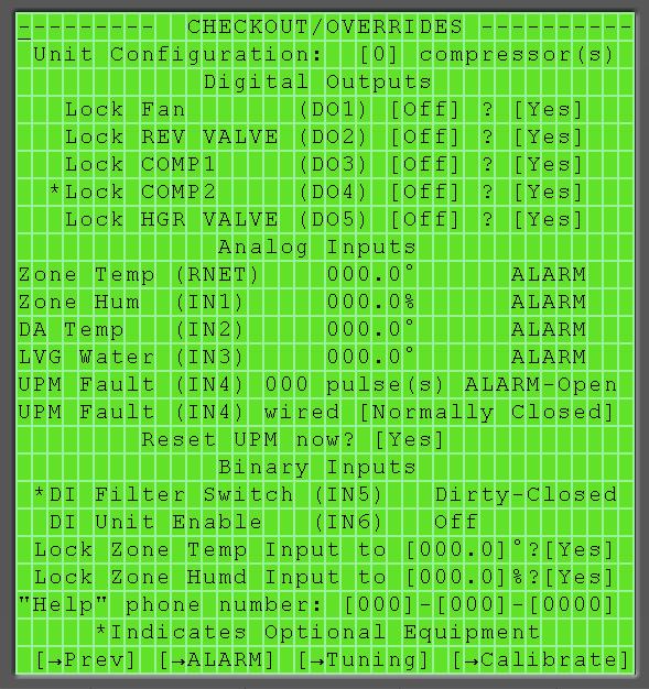
24 Figure 25 - Override/Checkout 24

25 Calibration Screen This screen can be accessed by pressing the following: Figure 25 Calibration + Once in the calibration screen the user may change the offset points for the different temperatures as shown in figure 25. From this screen the user can also access the calibration parameters and offset the sensors readings in order to test the unit prior or during the commissioning process. IMPORTANT: The BACview red LED is normally lit during an alarm condition (in normal operation mode). It will turn on once the user overrides a variable in order to alert or remind the user that the system is not operation according to its programmed sequence of operation but in overridden mode. 25
26 The RS-Pro Sensor interface The RS-Pro sensor FHP part number is a combination keypad/display unit that attaches to a control module to let you view and change temperature and set points values and the controller s components status, the following features only apply to the software version covered on this manual. ICONS Alarm Bell Cooling Heating Occupied Unoccupied Fan Indicates Alarm Condition (see INFO button for more information) Indicates unit enabled in cooling mode Indicates unit enabled in heating mode Indicates unit in occupied mode Indicates unit in unoccupied mode Indicates fan output energized BUTTONS ANUAL ON WARMER Places unit into occupied mode. Allows for incremental increase in override time ( 60min, 120min, 180 min, 4hrs, 5hrs, 6hrs, 0 min) each time button is pressed Allows for increase in zone temperature setpoint (+1 to per push to a maximum of +5 or as configured at DDC through BAC view6) from default setpoint value COOLER Allows for decrease in zone temperature setpoint (-1 to per push to a maximum of -5 or as configured at DDC through BAC view6) from default setpoint value. 26
27 IMPORTANT: INFO By Pressing the Info button on the sensor the user can see the following data: PRESS 1 Displays occupancy override time (in minutes) PRESS 2 Displays actual heating setpoint (in degrees F) PRESS 3 Displays actual cooling setpoint (in degrees F) PRESS 4 [ 1 ] - Displays discharge air temperature (in degrees F) PRESS 5 [ 2 ] - Displays leaving water temperature (in degrees F) PRESS 6 [ 3 ] - Displays active alarm code 0 Indicates NO ALARM 1 Indicates active HP alarm comp 1 2 Indicates active LP alarm comp 1 3 Indicates active HP alarm comp 2 4 Indicates active LP alarm comp 2 5 Indicates active freezestat alarm 6 Indicates active condensate alarm 7 Indicates brownout condition 20 Indicates input/out in MANUAL lock position. It is not in AUTO 30 Indicates RS zone, discharge, leaving water Temperature or relative humidity sensor failure 40 Indicates high or low leaving water temperature alarm 50 Indicates high or low RS zone temperature condition 60 Indicates high or low zone humidity condition 70 Indicates high or low discharge air temperature condition 80 Indicates filter or compressor service alarm PRESS 7 [ 1 ] Displays status of compressor 1 output (ON/OF) PRESS 8 [ 2 ] Displays status of compressor 2 output (ON/OF) PRESS 9 [ 3 ] Displays status of auxiliary heat output (ON/OF) PRESS 10 Displays fan status (fan icon=fan ON), unit condition (AU=auto) PRESS 11 Displays unit mode (AU=auto) PRESS 12 Goes back to default screen display 27
28 DDC ZONE I/O 560 FHP ORDER # LINE # - MODEL # FHP PART # SW VERSION 28
29 NOTES 29
30 601 N.W. 65 th Court, Ft. Lauderdale, FL Phone: Fax: REV
Quick Start Guide DDC (2014/02) Subject to change without prior notice Quick Start Guide
 Subject to change without prior notice Quick Start Guide") Quick Start Guide 560/583 DDC 8733914716(2014/02) Please refer to the included Hardware User s Guide and BACview Installation and Operation Manual for more detailed information on setting up and using
Quick Start Guide 560/583 DDC 8733914716(2014/02) Please refer to the included Hardware User s Guide and BACview Installation and Operation Manual for more detailed information on setting up and using
BACVIEW DEVICE INTERFACE For DDC Software Version Software Configuration Guide (11/2015)
") DEVICE INTERFACE For DDC Software Version 7.05.03 Software Configuration Guide 8733940857 (11/2015) 2 Table of contents TABLE OF CONTENTS Key to Symbols... 3 Warnings... 3 BACview Interfaces... 3 BACview
DEVICE INTERFACE For DDC Software Version 7.05.03 Software Configuration Guide 8733940857 (11/2015) 2 Table of contents TABLE OF CONTENTS Key to Symbols... 3 Warnings... 3 BACview Interfaces... 3 BACview
ExactLogic BACnet Communicating Thermostat EXL01816 Sequence Datasheet
 ExactLogic BACnet Communicating Thermostat EXL01816 Sequence Datasheet DataSheet ev 1.12.307/4.0 Jun 20, 2018 Operating Sequence Standard Occupied During normal occupied operation the display will show
ExactLogic BACnet Communicating Pressure Dependent VAV Damper Control with Heat EXL01820 Sequence Datasheet
 ExactLogic BACnet Communicating Pressure Dependent VAV Damper Control with Heat EXL01820 Sequence Datasheet DataSheet ev 1.12.307/4.0 June 14, 2018 Operating Sequence Standard Occupied During normal occupied
Introduction. To use Carrier wireless sensors, you must have: A i-vu v6.5 or later system v6-00 or later drivers
 Wireless Sensor CARRIER CORPORATION 2017 A member of the United Technologies Corporation family Stock symbol UTX Catalog No. 11-808-583-01 6/2/2017 Verify that you have the most current version of this
ExactLogic BACnet Communicating Zone Damper EXL01710 Sequence Datasheet
 ExactLogic BACnet Communicating Zone Damper EXL01710 Sequence Datasheet DataSheet ev 1.12.302/4.3 October 27, 2014 Operating Sequence Standard Occupied During normal occupied operation the display will
CommandCenter Operator Panel
 CommandCenter Operator Panel Introduction This document describes the different features of the Operator Panel (local or remote) that is used with the Seresco units. Startup Screens When the unit start
Touchpad User Guide. National Sales. Product Support. Freecall: Ph:
 Touchpad User Guide National Sales Ph: 1300 306 125 sales@ias.net.au Product Support Freecall: 1800 354 434 support@ias.net.au Designed and Manufactured in Australia by: Innovative Air Systems Pty Ltd.
Viconics VT76x6W Water-source Heat Pump Controllers Engineering Guide Specification
 Viconics VT76x6W Water-source Heat Pump Controllers Engineering Guide Specification General The VT76xxW series is designed for single-stage and multi-stage control of water source heat pumps with dedicated
BACnet FF Configuration Wizard Guide
 BACnet FF Configuration Wizard Guide TABLE OF CONTENTS SYSTEM ENGINEERING GUIDE INTRODUCTION... 3 WEBStation-AX... 3 Features... 3 BACnet FF Configuration Wizard... 3 BACnet FF Configuration Requirement...
FCU-4 FAN COIL CONTROLLER
 FCU-4 FAN COIL CONTROLLER BACnet Enabled Description The FCU-4 is designed to provide complete control of fan coil units. The FCU-4 incorporates all the inputs and outputs to ensure that this advanced
Touchpad User Guide (Model: C-LCD-122-TL)
") MESSAGE LIBRARY Refer to BBP-5 Instal Guide for information on input triggers. The same message may be linked to more than one trigger. ABBREVIATED VERSION DISPLAYED IN SELECTION SCREEN MESSAGE DISPLAYED
MESSAGE LIBRARY Refer to BBP-5 Instal Guide for information on input triggers. The same message may be linked to more than one trigger. ABBREVIATED VERSION DISPLAYED IN SELECTION SCREEN MESSAGE DISPLAYED
FCU-4 FAN COIL CONTROLLER
 FCU-4 FAN COIL CONTROLLER BACnet Enabled Description The FCU-4 is designed to provide complete control of fan coil units. The FCU-4 incorporates all the inputs and outputs to ensure that this advanced
V0STAT51P-2 Programmable Wired Controller
 PRODUCT SPECIFICATIONS VARIABLE REFRIGERANT FLOW SYSTEMS VRF V0STAT51P-2 Programmable Wired Controller Bulletin No. 210766 March 2016 Grouping - Controller can control up to 16 indoor units on the same
ExactLogic BACnet Communicating Thermostat EXL01716 Sequence Datasheet Duel Deck VAV
 ExactLogic BACnet Communicating Thermostat EXL01716 Sequence Datasheet Duel Deck VAV DataSheet ev 1.12.302/4.1 June 26, 2018 Operating Sequence Standard Occupied Thermostat occupancy can be set from a
htc HTC CONTROLS TEL:
 BUILDING AUTOMATION SYSTEM WebControl Quick Reference Guide htc HTC CONTROLS TEL: 46 3 3636 To Launch Open your Internet browser, then type your server s computer name, domain name, or IP address in the
Product Manual SZ2141
 Product Manual SZ11 Refrigeration Controller Communicating Controls Description The SZ11 is a microprocessor-based refrigeration controller and alarm interface designed to control three coolers or freezers
VTR8300 User Interface Guide VTR8300 Room Controller Series
 VTR8300 User Interface Guide VTR8300 Room Controller Series CONTENTS Home Screen Display 2 How to Enter Setup Screen 3 Setup Screen Display 3 Network Settings 4 ZigBee Network Settings 4 BACnet Network
AMBIFLEX MF626 - USER GUIDE
 AMBIFLEX MF626 - USER GUIDE CONTENTS Page No Product Overview 2 Features 3 Standby Display 4 User Facilities 5 Status Display Mode 6 Measured Temperatures 6 Time Channel Information 7 What is happening
DOC. #TD /20/06 PRINTED IN U.S.A. Lingo XE Touchscreen & Web Browser User s Guide
 DOC. #TD-0465 10/20/06 PRINTED IN U.S.A. Lingo XE Touchscreen & Web Browser User s Guide Logic One, Lingo, and iscope are registered trademarks of Novar. Ethernet os a registered trademark of Xerox Corporation.
Home Manager System Model TS40B Wall Display Operating Instructions
 4700 Lang Avenue McClellan, CA 95652 1.800.BEUTLER www.beutler.com Home Manager System Provides control for Heating and Air Conditioning Zoning Option SmartVent Option Security System Interface Option
HLS34 Modbus FCU/VAV Controllers installation instructions
 HLS34 Modbus FCU/VAV Controllers installation instructions The HLS34 is specifically designed for individual room temperature and zone control applications. The controllers have built-in RS-485 channel
Installation and Operation Instructions
 33ZC ComfortID Test and Balance Tool Software Installation and Operation Instructions Part Number 33ZCBAL-SA INSTALLATION The ComfortID Test and Balance Tool software requires no special installation.
BACnet MS/TP Interface User s Guide
 PoolPak MPK with CommandPak Control System CPCS BACnet MS/TP Interface User s Guide DOCUMENT #: SVW07-BACNET-MSTP-20171020 UPDATED: OCTOBER 2017 INTRODUCTION PoolPak dehumidifiers equipped with an CommandPak
FX 2 Instruction Manual
 FX 2 Instruction Manual Climma Compact Version Annapolis MD USA 301 352 6962 info@veco-na.com Introduction: The FX2-DX digital controller operates onboard air conditioning equipment to provide room temperature
Zio LCD Wall Modules TR70 AND TR70-H with Sylk bus
 Zio LCD Wall Modules TR70 AND TR70-H with Sylk bus OPERATING GUIDE PREFACE This Operating Guide is intended to provide configuration information (using the Niagara Workbench tool) and a general overview
Appendix C: HVAC PRO Modules
 FANs 637.5, 1637.5 Appendix Section Issue Date 0400 APPLICATION NOTE Appendix C: HVAC PRO Modules HVAC PRO Modules...3 Introduction...*3 Key Concepts...*4 ABS VALUE... 6 ADD... 6 ANALOG OUTPUT... 6 AND...
Zio Lite TOOL CONFIGURATION, NETWORK ACCESS, SYLK CAPACITY, AND OPERATION TR40/TR42
 Zio Lite TOOL CONFIGURATION, NETWORK ACCESS, SYLK CAPACITY, AND OPERATION TR40/TR42 Contents Tool Configuration... 1 General Settings Tab (Fig. 1).... 2 Categories and Parameters Tab (Fig. 4).... 5 Home
QUICK START. Installation & Programming Guide
 QUICK START Installation & Programming Guide PRECAUTIONS READ AND FOLLOW ALL SAFETY INSTRUCTIONS. CAUTION - RISK OF ELECTRICAL SHOCK. To prevent electrical shock, turn off power at the circuit breaker
Livezi Central. 4 speed fan Control System. Operating Instructions
 Livezi Central 4 speed fan Control System Operating Instructions 2 1 Operating Instructions The following pages detail the operation of the various control system types available for the Livezi ducted
VT8600 Series User Interface Guide Rooftop Unit, Heat Pump and Indoor Air Quality Controller
 1 User Interface Guide Rooftop Unit, Heat Pump and Indoor Air Quality Controller CONTENTS Home Screen Display 2 How to Enter Setup Screen 3 Setup Screen Display 4 ClockSettings 5 Schedule Settings 6 Occupancy
Dryer. M720 Programming and Operation Manual. July 15, 2015 Revision 1.51
 Dryer M720 Programming and Operation Manual July 15, 2015 Revision 1.51 Contents 1 Important Safety Information 1 1.1 FOR YOUR SAFETY - CAUTION!............................. 1 2 Control Overview 2 2.1
Model FP700 Owner s Instructions
 The benefits of owning a Freedom Advantage Thermostat Large easy to read backlit display Selectable programming modes: 5-2, 5-1-1 or 7 day Manufactured by the makers of ACCUSTAT controls ServiceWatch for
pco 3 Controller User Manual ASPX Digital Scroll, Air Packaged Chiller For Version MCDSV_A02
 pco 3 Controller User Manual ASPX Digital Scroll, Air Packaged Chiller For Version MCDSV_A02 pco 3 Controller User Manual Introduction The Airstack Chiller is a modular air-cooled chiller composed of
PoolPak MPK with CommandPak Control System CPCS BACnet /IP User s Guide DOCUMENT #: SVW07-MPKBACNIP
 PoolPak MPK with CommandPak Control System CPCS BACnet /IP User s Guide DOCUMENT #: SVW07-MPKBACNIP-20171020 UPDATED: OCTOBER 2017 INTRODUCTION PoolPak dehumidifiers equipped with an CommandPak Control
Modbus Integration Integration for Modbus Functionality for VTR8300 Series
 Modbus Integration Integration for Modbus Functionality for VTR8300 Series Building Management System *For data visualization and analysis Modbus Controller VT8000 Series room controllers 2 TABLE OF CONTENTS
Operation Guide CT101
 Operation Guide CT101 PG 1 The CT101 communicating Z-Wave thermostat operates via a high-quality, easy-to-use touch screen. To set or adjust your CT101, simply touch your finger firmly to the screen. The
Modular Service Tool SD Quick Start Guide
 www.orioncontrols.com Quick Start Guide Requires Code: SS1063 VCCX2 Controller Code: SS1088 VCC-X Controller Code: SS1079 and SS1062 VCB-X Controller Code: SS1051 Version 2.0 and up VCM-X Controller Code:
INSTRUCTIONS FOR USING THE CONTROL PANEL
 DIGIT SED ELECTRONIC CONTROLLER WITH LCD DISPLAY 1.09.370E 10.01.2007 VALLOX These instructions replace and complement the instructions for use and maintenance of the following VALLOX units: VALLOX DIGIT
Installation Guide. VZ7656F1000B BACnet MS-TP RTU Terminal Equipment Controller with Modulating Heat. February 2017 /
 VZ7656F1000B BACnet MS-TP RTU Terminal Equipment Controller with Modulating Heat Installation Guide For Commercial Zoning S ystems February 2017 / 028-0324-02 CONTENTS Installation 2 Location 2 Installation
Installation, Start-up and Operating Instructions
 Installation, Start-up and Operating Instructions EVOLUTION SMART SENSOR FOR ZONING Cancels: NEW II ZONESMS-0-1 7-04 NOTE: Read the entire instruction manual before starting the installation. This symbol
User Guide. For controller on CXAO / RTXB heat pumps CGCM / CXCM 2 circuit units. CNT-SVU005C-GB Original instructions
 User Guide For controller on CXAO / RTXB heat pumps CGCM / CXCM 2 circuit units CNT-SVU005C-GB Original instructions Table of contents Advanced electronics... 3 Technical Specifications... 4 Display description...
Quantum HD Release Notes
 Quantum HD Release Notes OS Version 10.17 Released 7-14-2014 To upgrade to OS version 10.17 directly the current OS version must be 10.13 through 10.16. To check the current OS version on the Quantum HD
Communicating Wall Control Owner s Manual TSTAT0101SC
 C O M M U N I C A T I N G S Y S T E M Communicating Wall Control Owner s Manual TSTAT0101SC U.S. Patent No. 7,243,004 U.S. Patent No. 7,775,452 616 02 1018 00 02/28/14 Table of Contents Introduction...
ADVANCED PROGRAMMING & FEATURES
 ADVANCED PROGRAMMING & FEATURES CompleteStat TM Controller CS9B-THOA CS9B-THOCA Models: CS9BE-THOA CS9BE-THOCA Bard Manufacturing Company, Inc. Bryan, Ohio 43506 www.bardhvac.com Manual: 2100-685 Supersedes:
Table of Contents RTU-MP
 RTU-MP Third Party Integration Guide CARRIER CORPORATION 2008 A member of the United Technologies Corporation family. Stock symbol UTX, 48-50H-T-1SB, Rev. 7/23/2008 Table of Contents Safety Considerations...
ZONETOUCH DAMPER CONTROL SYSTEM Operation Manual
 ZONETOUCH DAMPER CONTROL SYSTEM Operation Manual www.zonemaster.com.au www.polyaire.com.au 2012 Polyaire Pty Ltd TABLE OF CONTENTS 1) Features 2 2) Wall Controller Layout (Touchpad) 2 3) Manual On/Off
OPERATION INSTRUCTIONS
 2018 Lennox Industries Inc. Dallas, Texas, USA OPERATION INSTRUCTIONS V0STAT52 Wireless Indoor Unit Controller CONTROLS 507459-04 05/2018 This manual must be left with the owner for future reference. IMPORTANT
Model: Available in : Sapphire Black and Glacier White
 Model: Available in : Sapphire Black and Glacier White 1 Table of Contents Product Image 1 Locking/Unlocking the SmartStat 20 Table of Contents 2 Standby/Away Mode 21 What is a Programmable Room Thermostat?
Networkable Dual Duct VAV Controller Specification and Installation Instructions
 Controller Models EVCBM14NIT2S (Master controller / 2 TRIACs) EVCS14N (Slave controller) TRL Series Thermostat TRL24 (Room Sensor: Temp) TRLH24 (Room Sensor: Temp and %RH) TRLG24 (Room Sensor: Temp and
CONTROLLER INSTALLATION OPERATION & QUICK START
 CONTROLLER INSTALLATION OPERATION & QUICK START Controller: 8403-066 ECU Series Controller Manual: 2100-559 Supersedes: NEW File: Tab 19 Date: 05-02-11 Page 1 of 6 TABLE OF CONTENTS Installation Note...
Suitable for a wide range of installations with wall-mount, flush-mount and hand-held remote control options.
 TUC03 Configurable Terminal Unit Controller Product Bulletin The TUC03 Configurable Terminal Unit Controller is designed specifically to provide direct digital control of terminal unit applications with
WavePRO Wireless Programmable T2500 Thermostat & R2500 Receiver OPERATING MANUAL. Model K
 WavePRO Wireless Programmable T2500 Thermostat & R2500 Receiver OPERATING MANUAL Model K2500-001 1 THE PECO WAVEPRO WIRELESS SYSTEM Thank you for choosing the PECO WavePRO TM Wireless System (Model K2500-001).
Operation 6035 ENGLISH PROG MENU
 Operation 6035 PROG MENU ENGLISH Operation 6035 Program button Time of day Day Time Slot Current Room Temperature Target Temperature Menu button PROG MENU FAN AUTO ON COOL OFF HEAT Fan Switch Touch Screen
Modular System Manager SD Quick Start Guide
 www.orioncontrols.com Modular System Manager SD Quick Start Guide Requires Modular System Manager SD Code: SS1068 VCCX2 Controller Code: SS1088 VCC-X Controller Code: SS1079 VCB-X Controller Code: SS1051
FP735Si Electronic 3-Channel Full Programmer for Heating and Hot Water with Service Interval Timer. Installation Guide MAKING MODERN LIVING POSSIBLE
 MAKING MODERN LIVING POSSIBLE FP735Si Electronic 3-Channel Full Programmer for Heating and Hot Water with Service Interval Timer Danfoss Heating Installation Guide For a large print version of these instructions
Contents 1 Warnings, Cautions, and Notes Description Features... 1
 EnCell Contents 1 Warnings, Cautions, and Notes... 1 2 Description... 1 3 Features... 1 3.1 STANDARD FEATURES... 1 3.2 FRONT PANEL FEATURES... 2 3.2.1 Display... 2 3.2.2 OK LED... 2 3.2.3 FAULT LED...
ES 4000 STANDARD. 1 General information Document Overview General description Introduction... 4
 Controller Instruction 1 General information ES 4000 STANDARD Printed Matter Number : 2946 7002 09 Applicable to : MB compressors Preliminary Operations: : Safety Instructions : General Persons Required
Model: Available in : Sapphire Black and Glacier White
 1 Model: Available in : Sapphire Black and Glacier White 1 Table of Contents Product Image 1 Locking/Unlocking the SmartStat 20 23 Table of Contents 2 Standby/Away Mode Mode 21 24 What is a Programmable
ADVANCED OPERATOR PANEL (AOP)
") ADVANCED OPERATOR PANEL (AOP) Operating Instructions Issue 04/02 English Contents 1 Warnings and Notes 3 1.1 Special Key Functions 4 2 Applications Examples 4 2.1 Single drive control using the AOP 4 2.2
ADVANCED OPERATOR PANEL (AOP) Operating Instructions Issue 04/02 English Contents 1 Warnings and Notes 3 1.1 Special Key Functions 4 2 Applications Examples 4 2.1 Single drive control using the AOP 4 2.2
Operation Guide CT32 ENGLISH
 Operation Guide CT32 The CT32 communicating thermostat operates via a high-quality, easy-to-use touch screen. To set or adjust your CT32, simply touch your finger firmly to the screen. The screen will
VZ7656F1000W Zigbee Wireless RTU Terminal Equipment Controller with Modulating Heat. Installation Guide
 VZ7656F1000W Zigbee Wireless RTU Terminal Equipment Controller with Modulating Heat Installation Guide For Commercial Zoning S ystems Januar y 10 th, 2012 / 028-0325-R1 CONTENTS Installation 2 Location
STRA-17 Room controller. Installation and maintenance manual. Content
 Content Installation preparations... Wiring diagram...3 Display handling...5 Technical data...6 Configuration...7 Operating modes...7 Controller modes...7 Activation operating modes...7 Control states...8
LiteKeeper 4. Stand Alone Lighting Control Panel Technical Specifications PART 1. GENERAL 1.01 INTRODUCTION 1.02 DESCRIPTION OF WORK
 LiteKeeper 4 Stand Alone Lighting Control Panel Technical Specifications PART 1. GENERAL 1.01 INTRODUCTION The work covered in this section is subject to all of the requirements in the General Conditions
VZ7656B1000B Series BACnet RTU Thermostats For Commercial Zoning Systems
 VZ7656B1000B Series BACnet RTU Thermostats For Commercial Zoning Systems Product overview The Viconics VZ7656B1000B thermostat is specifically designed for RTU control and fits within the Viconics Zoning
Installation, operating and maintenance ADALINK II. Web solution for LENNOX units supervision ADALINK II-IOM-1401-E. lennoxemeia.
 Installation, operating and maintenance ADALINK II Web solution for LENNOX units supervision ADALINK II-IOM-1401-E lennoxemeia.com CONTENT 1 INTRODUCTION 1.1 - ADALINK II system description... 3 2 INSTALLATION
McQuay VAV System Controller
 Operation Manual OM 1092 Group: Controls Part Number: OM 1092 Date: September 2010 Supersedes: New McQuay VAV System Controller For the McQuay Delivered VAV System 2010 McQuay International Table of Contents
Field selectable application type and room module series, via dip-switches on controller
 TUC03 Plus Configurable Terminal Unit Controller Product bulletin The TUC03 Plus configurable Terminal Unit Controller is specifically designed to provide an improved BACnet integration. It allows the
Millennium Simplicity Elite Parameter Points and Quirks
 Millennium Simplicity Elite Parameter Points and Quirks How to access, view and change parameter settings Program Button Test Reset UP Alarms Change Data Address Down 1. Push the Program button once. The
OPERATION MANUAL. Room thermostat EKRTW
 OPERATION MANUAL 1 1 2 3 1 2 4 1 2 1 2 3 4 5 6 7 8 11 12 13 14 9 10 15 16 17 18 19 20 21 22 23 2 WARNINGS Never let the thermostat get wet, this may cause an electric shock or fire. Never press the buttons
VZ7656B1000W Series Wireless RTU Thermostats For Commercial Zoning Systems
 VZ7656B1000W Series Wireless RTU Thermostats For Commercial Zoning Systems Product overview The Viconics VZ7656B1000W thermostat is specifically designed for RTU control and fits within the Viconics Zoning
User Guide. Multipipe Units CMAA / RTMA CNT-SVU004B-GB
 User Guide Multipipe Units CMAA / RTMA CNT-SVU004B-GB USER GUIDE WARNING Supply the unit at least 24 hours before the initial startup to heat the compressor oil. In conditions of low water temperature,
Temperature control unit
 Temperature control unit 5739 18/19 Installation manual Part. U3582A - 12/08-01 PC Contents 1 - Introduction 5 1.1 - Warnings and tips 5 1.2 - Contents of package 5 2 - Description of the Control unit
DUKE UNIVERSITY DESIGN & CONSTRUCTION STANDARDS
 1 25 95 00 Integrated Automation Control Sequences for HVAC GENERAL The HVAC operational sequences in this guideline are commonly used by Duke University. They are being provided as a preferred design
Table of Contents pg " Display pg Cruise Mode pg Map Screen pg Stereo Screen pg Depth Screen pg.
 USER GUIDE TABLE OF CONTENTS Table of Contents pg. 2 12.3" Display pg. 3-4 Cruise Mode pg. 5-6 Map Screen pg. 6-13 Stereo Screen pg. 14-17 Depth Screen pg. 17 Settings Screen pg. 18-24 Media Screen pg.
CONTENTS. Installation Guide. PIR Ready VT7200 Series 24 VAC Low Voltage Zoning Terminal Equipment Controller
 PIR Ready VT7200 Series 24 VAC Low Voltage Zoning Terminal Equipment Controller Installation Guide For Commercial HVAC Applications Ma y 3 rd, 2012 / 028-0190-R8 CONTENTS Installation 2 Location 2 Installation
Product Manual SZ2144
 Product Manual SZ1 Refrigeration Monitor Communicating Controls Description The SZ1 is a microprocessor-based refrigeration monitor and alarm interface designed to monitor up to six coolers or freezers.
T7350 Keypad Configuration
 Setup Using Keypad T7350 Keypad Configuration QUICK GUIDE NOTE: Refer to Fig. 1 and Table 2 for keypad description and details. A combination of key presses are required to use the Installer Setup feature:
Operating Instructions
 33CS Comfort System Software CONTENTS Page GENERAL...1 OPERATION...1-11 Start-Up...1 Main Menu...2 CURSOR MOVEMENT AND FUNCTION SELECTION Initial Setup and Configuration...3 BASIC MODE EXPERT MODE MODEM
MiG2 CONTROLLERS. 2 & 4 Stage General Purpose Controllers, with Air-conditioning Facilities
 MiG2 CONTROLLERS 2 & 4 Stage General Purpose Controllers, with Air-conditioning Facilities The MiG2 controllers incorporate: 2 Inputs (Configurable as Resistive, 0 10V, 0 20mA or 4 20mA) 2 or 4 Relay Outputs
VZ7656R1000W / VZ7656H1000W Zigbee Wireless RTU / HP Terminal Equipment Controllers. Installation Guide
 VZ7656R1000W / VZ7656H1000W Zigbee Wireless RTU / HP Terminal Equipment Controllers Installation Guide For Commercial Zoning S ystems Januar y 10 th. 2012 / 028-0323-R1 CONTENTS Installation 2 Location
FX2-CHILLER. Digital Control. Operations Manual
 FX2-CHILLER Digital Control Operations Manual Micro Air Corporation Phone (609) 259-2636 124 Route 526 www.microair.net Allentown NJ 08501 Fax (609) 259-6601 Introduction: The FX2-CHILLER digital control
MicroTech II ServiceTools for Applied Air Handling Unit Controllers
 Users Manual UM 734-6 Group: Controls Part Number: UM 734 Date: June 2007 Supersedes: UM 734-5 MicroTech II ServiceTools for Applied Air Handling Unit Controllers Rooftop Models RPS, RAH, RDT, RFS/RCS,
Instructions. Installation and Operation of the Prodigy Smart-Board, KSB
 Instructions Installation and Operation of the Prodigy Smart-Board, KSB Scotsman's Advanced Feature Smart-Board is an optional add on electronic device that can be applied to most Prodigy models. It can
VTR8300 User Interface Guide Commercial and Hotel/Lodging HVAC Fan Coil Applications
 VTR8300 User Interface Guide Commercial and Hotel/Lodging HVAC Fan Coil Applications CONTENTS Home Screen Display 2 How to Enter Setup Screen 3 Setup Screen Display 4 ClockSettings 5 Schedule Settings
ACDU01A Communicating Service Tool
 Operation Manual 97B0106N02 Created: 10/1/12 Caution: These instructions are intended to be used by the installer or service personnel. End users are NOT advised to change or modify any of these settings.
VZ7656E1000W Zigbee Wireless RTU Terminal Equipment Controller with IAQ Control. Installation Guide
 VZ7656E1000W Zigbee Wireless RTU Terminal Equipment Controller with IAQ Control Installation Guide For Commercial Zoning S ystems Januar y 10 th, 2012 / 028-0327-R1 CONTENTS Installation 2 Location 2 Installation
Instructions. Installation & Operation of the Prodigy Smart-Board, KSBU-N
 Instructions Installation & Operation of the Prodigy Smart-Board, KSBU-N Scotsman's Advanced Feature Smart-Board is an optional add on electronic device that can be applied to most Prodigy models. It can
Submittal Data Sheet intelligent Touch Manager DCM601A71
 For use with the following VRV Models: FXAQ, FXDQ, FXEQ, FXFQ, FXHQ, FXLQ, FXMQ, FXMQ_MF, FXNQ, FXTQ, FXUQ, FXZQ, VAM For use with the following Daikin SkyAir Models: FAQ, FBQ, FCQ, FHQ, FTQ Capacity:
FOCUS GUIDE NETWORK CONTROLLER. Configuration Guide for ProLon Focus Software
 FOCUS GUIDE NETWORK CONTROLLER Configuration Guide for ProLon Focus Software www.proloncontrols.com info@proloncontrols.com 17 510, rue Charles, Suite 100, Mirabel, QC, J7J 1X9 REV. 6.2.0 PL-FOC-NC-C/F-EN
Contents Introduction 2 Getting Started 3 Messages Function Menus Contents Maintenance
 User Manual Contents Introduction Pager Features Getting Started Battery Information Battery Installation and Removal Button Definition Pager On Pager Off Backlight Main Menu Screen Function Menus Alert
Service Bulletin SB685. Date: 8/18/2017 TriPac EVOLUTION Communications Update Bulletin Location: TSA Info Central\Service Bulletins
 Service Bulletin SB685 Date: 8/18/2017 Subject: TriPac EVOLUTION Communications Update Bulletin Location: TSA Info Central\Service Bulletins Units: All TriPac EVOLUTION Summary: This bulletin updates and
SE8300 User Interface Guide SE8300 Series Room Controller
 1 SE8300 User Interface Guide Room Controller Commercial and Hotel/Lodging HVAC Fan Coil Applications CONTENTS HMI Display 2 How to Enter Setup Screen 3 Setup Screen Display 3 Schedule Menu 4 Clock Settings
Control Equipment Limited 96 Zone Discovery Panel, 32 Zone Voyager Panel and Integra Network Repeater 40- Character User Manual
 Created by: A.C. Revised by: G.G. Approved by: JBJ Control Equipment Limited 96 Zone Discovery Panel, 32 Zone Voyager Panel and Integra Network Repeater 40- Character User Manual Table of Contents 1. Introduction...3
SEZ7656R1045B / SEZ7656H1045B
 SEZ7656R1045B / SEZ7656H1045B Installation Guide f BACnet MS-TP RTU / HP Room Controllers F Commercial Zoning Systems CONTENTS Installation 2 Location 2 Installation 2 BACnet System Overview 3 Terminal,
OPERATION MANUAL.
 OPERATION MANUAL 1 2 The Prodigy control system is the latest example of Lennox commitment to advanced HVAC technology. Standard on every Strategos rooftop unit, the Prodigy control system makes setup,
CS2000 Automatic control V3 Quick Guide
 112626E-03 2017-09 CS2000 Automatic control V3 Quick Guide ! All electrical connections must be made by an expert. 2 Contents! This quick guide only applies to software version V3.x To view current software
WSHP-IOP-2 May Installation, Operation, and Programming. Tracer ZN510 Controller
 WSHP-IOP-2 May 1998 Installation, Operation, and Programming Tracer ZN510 Controller Literature History The Trane Company has a policy of continuous product improvement and it reserves the right to change
Installation and Operation. Tracer MP501 Controller CNT-SVX08B-EN
 Installation and Operation Tracer MP501 Controller CNT-SVX08B-EN Installation and Operation Tracer MP501 Controller CNT-SVX08B-EN April 2005 CNT-SVX08B-EN Tracer MP501 Controller Installation and Operation
What is the Equipment Touch App?
 Equipment Touch App CARRIER CORPORATION 2018 A member of the United Technologies Corporation family Stock symbol UTX Catalog No. 11-808-652-01 4/24/2018 Verify that you have the most current version of