BD Laser User Guide * IMPORTANT * PLEASE READ THE FOLLOWING INSTRUCTIONS CAREFULLY AS IMPROPER USE MAY DAMAGE THE MACHINE AND VOID THE WARRANTY.
|
|
|
- Gloria Robbins
- 5 years ago
- Views:
Transcription

1 BD Laser User Guide * IMPORTANT * PLEASE READ THE FOLLOWING INSTRUCTIONS CAREFULLY AS IMPROPER USE MAY DAMAGE THE MACHINE AND VOID THE WARRANTY. BD Laser arrives ready to use with jaws and cutters preinstalled. For best performance, calibrate the jaws prior to use. Do not calibrate cutters. To cut a key, select vehicle Make/Model/Year and follow the screen prompts. BD Laser will inform you when/how to change Jaw/cutter/tracer if required. May
2 Table of Contents Section Page # Setting up BD Laser 3 Password Entry 4 Important Notice 5 Jaw Calibration 6 F-Jaw Calibration 17 Cutter Calibration (do not calibrate 1.5mm cutter) 7 Cut by Code 8-10 Cut by Decode Changing the Tracer 13 Changing Worn Cutters 14 F Jaw Accessory Software Updates Internet Direct Connect 23 Short Form Instructions 24 2

3 Setting up the BD Laser How to connect cables and turn the machine ON 1. Attach the 9-pin connector cable to the LOWER port on the back of the console AND to the back of the machine. SECURE WITH ATTACHED SCREWS. 2. Attach power cord to back of machine and plug into a properly grounded outlet. 3. Make sure the ON/OFF switch above the power cord is to the ON position. 4. Rotate the emergency stop button towards the back of the machine until it releases outward. 5. The machine will now begin to start-up. This process takes a few seconds. Proceed with password entry. How to turn OFF the machine 1. You may select MAIN MENU from any screen. 2. Select: EXIT 3. Select: OFF 4. Screen will display NOW YOU CAN TURN OFF THE MACHINE. 5. Press the emergency stop button to turn OFF the machine. 3
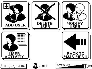
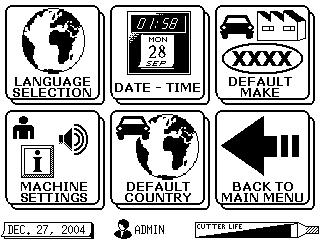
4 Quick Start Password Entry 1. Type in Master Password: Touch Screen For best results use a nonmetallic stylus such as a plastic tip end of a pen, tip of brush handle, etc Press: YES* is now ready for use. * If YES is selected the following should occur for new BD Laser installation: The password default is , and should be changed by the assigned Administrator for continued security of the BD Laser. Note: If the password is not changed, anyone will have access to secured screens using the default password. The new master administrator password should be documented and stored in a safe place. The master (Administrator) password permits access to all screens. All other user passwords will not have access to secure screens. At least one additional new password should be assigned for users other than the Administrator. To add additional users see page 36 of your BD Laser manual (comes in box with machine when shipped) 4
5 IMPORTANT Before using the BD Laser for the first time, please calibrate each jaw. Follow the directions on pages 6 and 7 of this guide. The required template can be found in the black accessory case. Calibration is necessary to correct fluctuations and changes that may have occurred during shipment. Failure to follow this procedure correctly may cause damage to the tracer, cutter, and/or jaw and may result in voiding the warranty. If you have any questions on these procedures, please contact the Program Support Center Phone: option #2 KeyMachines@MSCDirect.com 5
6 Jaw Calibration Procedure High Security Jaws: red, green, blue and gray 1. Select: SETUP/TEST 2. Select: SETUP 3. Select: JAW SETUP 4. Select: Desired Jaw (use DOWN arrow to select other jaws). Install Jaw to far left of carriage until it stops. CLAMP TIGHT WITH JAW LEVER. 5. Insert the silver jaw set-up template. (metal bar with key ring in accessory kit). Hold template FLAT in jaw & press down while tightening. Press: YES to calibrate jaw 6. SETUP OK Remove template. Press: OK 6
. DO NOT CALIBRATE THE 1.5MM DIA. CUTTER 1. Select: SETUP/TEST 2.")

7 Cutter Calibration Procedure Calibrate the jaw prior to calibrating the cutter. (See jaw calibration procedure on page 6). DO NOT CALIBRATE THE 1.5MM DIA. CUTTER 1. Select: SETUP/TEST 2. Select: SETUP 3. Select: CUTTER SETUP 4. Insert brass test blank (from toolbox). Press: YES 5. The tracer will locate the jaw. 6. Cutter will notch brass blank. 7. Remove all chips from key with brush. Press: YES 8. Tracer will verify calibration. Press: OK. Remove blank. 7
 Select desired model If desired make is not displayed Touch: Down Arrow to view additional makes. Touch desired make. 5. YEAR: (ex.")
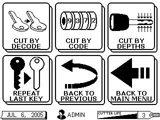
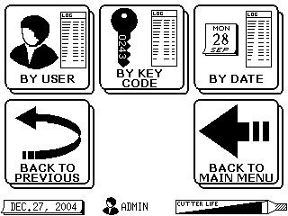
8 Cut by Code WARNING: Each jaw is matched to a single tracer/cutter kit for the calibration process. The console will warn user to change tracer and/or cutter when necessary. 1. Select: KEY SEARCH 2. Select: CAR MODEL SELECTION 3. MAKE: (ex. Ford) Select desired model If desired make is not displayed Touch: Down Arrow to view additional makes. Touch desired make. 5. YEAR: (ex ) Select desired year If desired year is not displayed Touch: Down Arrow to view additional years. Touch: desired year 4. MODEL: (ex. Aerostar) Select desired model If desired model is not displayed Touch: Down Arrow to view additional models. Touch desired model. 6. Select: CUT BY CODE 7. Enter the desired key code Note: Some codes have prefix/suffix already entered on screen. ( ) 8. Verify the key code is correct. If not, press PREV and re-enter. If correct, 8
 (Be sure the tip stop tool is not on the jaw at this time.) 14. Remove stop tool (if not done previously) Press: OK (table will move into position) 15. Install 1.5mm (.")
9 Cut by Code 9. Key blank reference list is Displayed. 10. STOP! Please Remove Jaw 11. Remove cutter from spindle and DO NOT INSTALL another cutter 12. Are you sure that no cutter is in the spindle? 13. Insert F Jaw (purple) (Be sure the tip stop tool is not on the jaw at this time.) 14. Remove stop tool (if not done previously) Press: OK (table will move into position) 15. Install 1.5mm (.059 ) diameter cutter and lock it in contact with jaw. Ready? Press: YES 16. Insert tip stop (tang toward front of jaw) in groove indicated. Insert key by pressing down while holding flat until tip contacts tip stop.tighten Clamp. Press: YES 423 Ford 4ETF1 8+8 A LL 10123X purple F1 9
 Key cutting will begin.")
10 Cut by Code 17. REMOVE STOP TOOL (if not done previously) 18. Press: OK (table will move into position) Key cutting will begin. Once complete, brush off all chips and remove the key blank. 10
 Select desired model. If desired make is not displayed Touch: Down Arrow to view additional makes. Touch desired make. 4. MODEL: (ex.")
11 Cut by Decode WARNING: Each jaw is matched to a single tracer/cutter kit for the calibration process. The console will warn user to change tracer and/or cutter when necessary. 1. Select: KEY SEARCH 2. Select: CAR MODEL SELECTION 3. MAKE: (ex. Ford) Select desired model. If desired make is not displayed Touch: Down Arrow to view additional makes. Touch desired make. 4. MODEL: (ex. Aerostar) Select desired model If desired model is not displayed Touch: Down Arrow to view additional models. Touch desired model. 5. YEAR: (ex ) Select desired year. If desired year is not displayed Touch: Down Arrow to view additional years. Touch: desired year. 6. Select: CUT BY DECODE CONTINUE 11
12 Cut by Decode 7. Insert jaw and clamp tight. Insert original key blank, pressing down on blank while clamping jaw tight. 8. Press: YES Decoding in process 9. Verify decoded key. 10. Key blank reference list is displayed. 11. Remove original key. Insert new key blank, pressing down on blank while clamping jaw tight. 12. Press: YES Key cutting will begin. Once complete, brush off all chips and remove the key blank. 12

13 Tracer Change 1. Select: SETUP/ TEST 2. Select: SETUP 3. Select: TRACER CHANGE Use small T-wrench to loosen tracer setscrew. 2. Insert into hole in right side of shield 3. Unscrew 4 turns 4. Pull out tracer 5. You may use pliers to remove the tracer if it is broken or bent. 1. Remove Jaw 2. Make sure the red lever is flipped to the right 3. Remove the chip tray by lifting up the front of tray and tilting tray backward 4. CAREFULLY slide the tray to the left. Use caution when moving components near the tracing pin. 5. Press: OK Install new tracer as far up as it will go - you cannot go too far. 2. Be sure flat side of tracer is to the right to allow the setscrew to seat properly. 3. Tighten setscrew. Do not over tighten. 13


14 Cutter Change 1.5mm dia. cutter must use F-Jaw 2.5 / 3mm dia. cutters use d with jaws A - D Select: SETUP TEST Select: SETUP Select: CUTTER CHANGE BE SURE TO INSTALL THE SAME DIAMETER CUTTER AS SHOWN ON THE BOTTOM RIGHT HAND CORNER OF THE DISPLAY! 1. Insert red rod through hole in top of machine 2. Rotate rod until it drops into position 3. Press down to lock onto cutter 4. Rotate until arrow on red rod points left (9 o clock position) 5. Insert LONG T-wrench into black collar on left side of cutter guard 6. Loosen 4 turns. Leave wrench in place 7. Remove red rod with cutter attached 8. DO NOT install new cutter at this time. 9. ** DO NOT INSTALL CUTTER ** Press CONTINUE 10. Insert new cutter (SAME DIAMETER) on red rod Pressing in until it clicks 11. Insert red rod with new cutter through hole in the top of the machine 12. Rotate until cutter rests lightly on the silver dot on the Jaw 13. Tighten setscrew with the long T-wrench 14. Remove T-wrench and red rod Press: YES Reset Cutter Counter? Press: YES (only if cutter is new) 14

15 F-Jaw Accessory for edge-cut / traditional key cutting * IMPORTANT * The BD Laser will provide guided instruction when switching from cutting a side milled key to an edge cut key and vice versa. Please take time to read the information on the screens to ensure properly cut keys. May

 Key Tip and")

16 F Jaw Features Tip Stop Tool Note: The Tip Stop Tool tang position for proper orientation on F Jaw. Shoulder Stop Notch (F) Key Tip and Shoulder Stop Notch Positions Examples of Key Tip and Shoulder stop positions 16
17 F-Jaw Checklist Review Before Use Software Verification (Must be 4.0 (321) minimum) SELECT: Machine Data -> Machine Data. Must update software version if not 4.0 or higher. Jaw Verification Each jaw must be calibrated to the machine before selecting them for use. An * asterisk will be displayed next to each jaw displayed on the Jaw Setup screen indicating successful calibration. Cutter Verification Cutter life meter on screens will display current cutter installed. Either 1.5, 2.5 or mm dia. is for all Flat (edge cut keys). 2.5 mm dia. is for all High Security (side mill keys) including Honda. 3 mm dia. is for High Security HONDA ONLY (optional). Tracer Verification All tracers are 1.5 mm dia. STD (for High Security keys) tracer is short in length. LT02 (for Flat/Traditional/Edge-cut keys) tracer is longer in length. Key Verification High Security: side-mill, laser cut, wave, etc. (Use with Jaws A, B, C, D) Edge-cut: traditional, flat, etc. (Use with Jaw F) Cutting by Code Helpful Reminders If changing from high security to edge-cut key cutting or vice versa, you will only need to change the cutter. Regardless of which key had previously been cut, select the key that needs to be cut and follow on-screen prompts to change cutter. BD Laser will notify you IF and WHEN you have to change the cutter. Do not attempt to switch cutters without following screen instructions. Duplicating (copy / trace) When attempting to duplicate a key the proper TRACER MUST BE INSTALLED. 1. Select the desired vehicle by MMY (make/model/year) or RN (record number if known) 2. Continue selecting through the desired screen options to cut key 3. BD Laser will notify you IF and WHEN you have to change the Tracer. 17
18 F Jaw Key Cutting Tips If the BD Laser was ordered with F jaw accessory, the machine is ready for use. If the F Jaw was an add-on option, a software update must be completed if version is less than 4.0. Cutting by Code Easiest way to switch back and forth to cut high security and edge cut keys. As users selects the desired vehicle information, the screens will indicate when to change the cutter (if necessary) as you move along in the key cutting process. If user primarily cuts by code and has the high security cutter and (short) tracer installed, the cutter is only changed when switching from either style (edge or high security). To cut key: Select vehicle by Make/Model/Year or enter RN (record number if known). Continue selecting through the desired screen options. Machine will notify IF and WHEN the cutter needs changed. WARNING: Do not attempt to switch cutters without following on-screen prompts. Duplicating (copy / trace) Machine will notify user IF and WHEN the tracer needs changed. Do the following: Select vehicle by Make/Model/Year or enter RN (record number if known). Tracer and cutter change will be made without having to leave the decoding or cutting process. Disclaimer - There are multiple diameter cutters and different length tracers that may be used in the key cutting process. It is the responsibility of the user to correctly install the components when instructed. While the BD Laser will indicate which cutter and/or tracer to use, it cannot sense which cutter or tracer is physically installed. 18
 7. STOP Insert and fix TL02 (long) tracer in correct position. 9.")
. Hold blank template FLAT in jaw & press down while tightening. Press: YES to calibrate jaw 15.")
19 F-Jaw Calibration Procedure 1. Select: SETUP/TEST 2. Select: SETUP 3. Select: JAW SETUP 4. Select: Jaw F (use DOWN arrow to select it) 5. STOP Remove Jaw 8. STOP 6. STOP Remove Tracer Remove cutter from spindle and DO NOT install another cutter 10. STOP Please insert the F Jaw (purple) 7. STOP Insert and fix TL02 (long) tracer in correct position. 9. STOP Are you SURE that no cutter is in the spindle? 11. STOP Remove tip stop tool Press: OK 12. STOP Remove tip stop tool Press: OK 14. Insert the silver jaw set-up template (metal bar with key ring in accessory kit). Hold blank template FLAT in jaw & press down while tightening. Press: YES to calibrate jaw 15. SETUP OK Remove template Press: OK 13. STOP Install 1.5mm dia. cutter and lock in contact with jaw. Ready? Press: Yes 19


20 F Jaw SET-UP/Calibration 1. From the main menu, Press: SETUP TEST 2. Press: SETUP button. 3. Press: JAW SETUP 4. Press the DOWN ARROW to find F Jaw. Select the F JAW and press ENTER. 20
21 WARNING: Each jaw is matched to a single tracer/cutter kit for the calibration process. The console will warn user to change tracer and/or cutter when necessary. When prompted to change both tracer and cutter, the following screens will appear: 5. Remove jaw. 6. Remove currently installed tracer. 7. Install the correct tracer. 8. Remove currently installed cutter. 9. Make sure no cutter is currently installed in the spindle. 10. Install F Jaw (purple knob) as required. 11.!! Remove Stop Tool Then press OK 12. Install the required cutter (1.5 mm sized) and lock it in contact with jaw. Press: YES 13. Insert template on the jaw REMOVE the TIP STOP, then begin calibration by pressing YES. 13. Calibration of F Jaw will start. When SETUP OK is displayed, remove the template and F 0 Press: OK OK 21
22 F Jaw Cutter Calibration Procedure It is not necessary to calibrate the 1.5mm dia. cutter 22

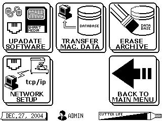
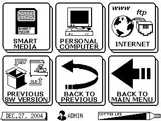
23 Update Software via Internet Verify existing software version 1. Touch: MACHINE DATA 2. Touch: MACHINE DATA 3. Software version can be found under the word console. 4. Touch: MAIN to return to main screen. To Update BD Laser Software via Internet Process time is approximately min. 1. Turn on BD Laser and enter the machine password 2. From main menu, select: A. Touch - Setup/test (top center) B. Touch - Software Update (bottom left) C. Touch - Update Software (top left) D. Touch Internet (top right) 3. Connect BD Laser console with working Ethernet cable NOTE: Phone option will take approximately 1 hour and is not recommended 4. Press: OK 5. Then wait do nothing until blue screen displays: Update Complete 6. If the message asks if you want to start axis-firmware update? A. If the original software was less than 3.1, Press: YES. NOTE: By selecting yes, additional time will be added to the process. B. If original software was higher than 3.1, Press: NO. NOTE: You will think the process is complete on some screens because of time delay, wait until you see the blue screen stating: UPDATE COMPLETE 7. Press: OK 8. Disconnect Ethernet cable or phone line from BD Laser console. 9. Return to main screen. NOTE: It is not necessary to recalibrate the jaw or the cutter. Modem connection 23

24 Short Form Instructions 24
994 LASER QUICK GUIDE
 994 LASER Quick-Start Guide CONTENTS Machine set-up & password entry Jaw calibration Cut by code & decode How to replace the cutter & change the tracer Short form instructions Replacemente parts list IMPORTANT
* IMPORTANT * REGISTERING YOUR MACHINE
 * IMPORTANT * REGISTERING YOUR MACHINE Thank you for your purchase of the Keyline 994 Laser. Before continuing with machine setup and use, please complete the following; COMPLETE PRODUCT REGISTRATION FORM
Triax A/T QUICK START GUIDE
 Triax A/T QUICK GUIDE Please read all instructions carefully before operating your Triax A/T Key Machine. 1. Preparation A. First remove the Triax A/T machine from its cardboard box and pallet. The machine
User Guide Instruction Manual
 User Guide Instruction Manual Please wear Safety Glasses at all times while operating this machine. DO NOT attempt to lubricate the machine. Clean only with a brush and or vacuum. Shield must be lowered
Nov. 07, 2013 p. 5 - changed the B axis unit value to from Changed by Randy per Frank s request.
 Correction notes Nov. 07, 2013 p. 5 - changed the B axis unit value to 45.1389 from 40.0000. Changed by Randy per Frank s request. Jan. 22, 2018 p. 5 - changed the B axis unit value and corresponding picture
Replacement Instructions
 imac G5 Inverter, 20-inch Replacement Instructions Follow the instructions in this document carefully. Failure to follow these instructions could damage your equipment and void its warranty. Note: Online
To connect the AC adapter:
 Replacing the AC Adapter Replacing the AC Adapter 3 Plug the power cord into a wall outlet. The power indicator turns on. To connect the AC adapter: Connect the power cord to the AC adapter. Power indicator
3 Indexer Installation For PRSalpha Tools
 888-680-4466 ShopBotTools.com 3 Indexer Installation For PRSalpha Tools Copyright 2016 ShopBot Tools, Inc. page 1 Copyright 2016 ShopBot Tools, Inc. page 2 Table of Contents General Safety and Precautions...5
5. Tools. Blue SHARK 123SHARK
 5. Tools 5.1 Edit DSD Presets 5.2 Machine Adjustments 5.3 Custom DSDs 5.4 DSD Specific Adjustments 5.4.1 Cut Styles 5.5 Decode 5.6 Special Function 5.7 Security 31 5.1 Edit DSD Presets The Tools section
FuturaPRO. Electronic Key Cutting Machine
 FuturaPRO Electronic Key Cutting Machine FuturaPRO The Next Generation The Ultimate Electronic Key Cutting Experience The original Futura electronic key cutting machine was the first machine on the market
Tactical Weather Station Set-Up Guide 1
 Tactical Weather Station Set-Up Guide 1 This is a generic overview of a portable WEATHERPAK 3 meter tripod set-up. Your system may not include all of the components listed, or may have different components.
Dell Edge Gateway. Service Manual Series
 Dell Edge Gateway 5000 Series Service Manual Computer Model: Dell Edge Gateway 5000/5100 Regulatory Model: N01G/N02G Regulatory Type: N01G001/N02G001 Notes, cautions, and warnings NOTE: A NOTE indicates
Danalock V3 BT HK EU Mounting guide
 Danalock V3 BT HK EU Mounting guide Page 2 Table of contents Tools needed page 6 Parts involved page 6 Contents of the Danalock box page 7 1. Remove the old cylinder page 8 2. Pull out the old cylinder
BreezeMAX Wi² and BreezeACCESS Wi² Quick Installation Guide
 This Quick Installation Guide is intended for experienced installers. For more information refer to the relevant sections in the BreezeMAX Wi² and BreezeACCESS Wi² System Manual. Wi² Package Content Check
Installing 6 Indexer: PRS Standard Tools
 888-680-4466 ShopBotTools.com Installing 6 Indexer: PRS Standard Tools Copyright 2016 ShopBot Tools, Inc. page 1 Copyright 2016 ShopBot Tools, Inc. page 2 Table of Contents Overview...5 Installing the
OPERATING USER MANUAL for PRESSURE RECORDERS
 Serial No. OPERATING USER MANUAL for PRESSURE RECORDERS MNW-004 Rev. E 03/21/16 Palmer Instruments Inc. 234 Old Weaverville Road Asheville, NC 28804 Toll Free: 800-421-2853 Phone: 828-658-3131 Fax: 828-658-0728
A-dec 570L Dental Light on a DCS System INSTALLATION GUIDE
 A-dec 570L Dental Light on a DCS System INSTALLATION GUIDE C ONTENTS Choose an Installation Guide...... Before You Begin.............. 3 Disconnect the Light Cable........ 3 Cut the Light Cable............
Removal and Installation8
 8 Screw Types 8-4 Top Cover Assembly 8-5 Left Hand Cover 8-6 Right Hand Cover 8-10 Front Panel Assembly 8-14 Left Rear Cover 8-15 Right Rear Cover 8-16 Extension Cover (60" Model only) 8-17 Media Lever
Quick start guide for p5 520 ( )
") Quick start guide for p5 520 (9111-520) 1 Before you begin This Quick start guide contains an abbreviated set of setup instructions designed to help you quickly unpack and set up a standard system. Users
Quick start guide for p5 520 (9111-520) 1 Before you begin This Quick start guide contains an abbreviated set of setup instructions designed to help you quickly unpack and set up a standard system. Users
KM-4800w. Installation Guide
 KM-4800w Installation Guide TABLE OF CONTENTS page 1 Installation Requirements 2 2 Unpacking 3 2. 1 Unpacking 3 2. 2 Confirmation of Accessories 5 3 Leveling the Machine 7 4 Setup of the Roll Deck 9 5
Installing the RZ26 Hard Disk Drive in the BA42 Expansion Box
 Installing the RZ26 Hard Disk Drive in the BA42 Expansion Box EK BA42A AD. A01 January 1993 Dear BA42 Expansion Box Customer: This document describes how to install the RZ26 hard disk drive in your BA42
Quick start guide for i5 520 ( or )
") Quick start guide for i5 520 (9405-520 or 9406-520) 1 Before you begin This Quick start guide contains an abbreviated set of setup instructions designed to help you quickly unpack and set up a standard
Quick start guide for i5 520 (9405-520 or 9406-520) 1 Before you begin This Quick start guide contains an abbreviated set of setup instructions designed to help you quickly unpack and set up a standard
OPERATING INSTRUCTIONS:
 List OPERATING INSTRUCTIONS: Preparation For Installation, Product Identification Charging The Batteries ing And Adjusting The Lift Mounting Head s Brackets Mounting Clamps And Quick-Locking Arms Installation
EPSON ActionLaser Read This First. eepa POLLUTION PREVENTER
 EPSON ActionLaser 1400 Read This First eepa POLLUTION PREVENTER This booklet is to help you set up your printer and begin printing quickly. It also gives you instructions for routine maintenance. If you
Serial ATA Hot Swap Drive Cage Upgrade Kit for: Intel Server Chassis SC5200 Intel Server Chassis SC5250-E
 Serial ATA Hot Swap Drive Cage Upgrade Kit for: Intel Server Chassis SC5200 Intel Server Chassis SC5250-E A Guide for Technically Qualified Assemblers of Intel Identified Subassemblies/Products Order Number:
How To Install: C4000 EMV Upgrade Kit
 How To Install: C4000 EMV Upgrade Kit IMPORTANT: Before proceeding with installation please verify you have the current card reader bezel in the kit. Correct bezel will have a small eject pin hole below
JLTX Lever and Joystick Replacement Instructions
 JLTX Lever and Joystick Replacement Instructions WARNING THE INCORRECT INSTALLATION OF A LEVER OR JOYSTICK CAN CAUSE AN EQUIPMENT MALFUNCTION FAILURE TO FOLLOW THIS PROCEDURE CAREFULLY COULD RESULT IN
Epson SureColor F6070 Setup Guide
 Epson SureColor F6070 Setup Guide 2 Unpacking and Assembling the Printer Read all of these instructions before using your printer. Also be sure to follow all warnings and instructions marked on the printer
TIVO UPGRADE INSTRUCTIONS (c) , Adberg Consulting LLC. All rights reserved.
 , Adberg Consulting LLC. All rights reserved.") TIVO UPGRADE INSTRUCTIONS (c) 2001-2003, Adberg Consulting LLC. All rights reserved. Instructions for Series 1 DirecTV/TiVo GXCEBOT TWO-DRIVE REPLACE upgrade Color instructions are also available at http://www.weaknees.com/upgrade_instructions.php
TIVO UPGRADE INSTRUCTIONS (c) 2001-2003, Adberg Consulting LLC. All rights reserved. Instructions for Series 1 DirecTV/TiVo GXCEBOT TWO-DRIVE REPLACE upgrade Color instructions are also available at http://www.weaknees.com/upgrade_instructions.php
Quicksilver 606 TR-606 CPU Upgrade
 Quicksilver 606 TR-606 CPU Upgrade D650C 128 Installation Guide Social Entropy Electronic Music Instruments TABLE OF CONTENTS WARNINGS... 1 OVERVIEW... 2 WHAT'S IN THE BOX... 3 OPENING THE TR-606 CASE...
Copyright 2007 Hewlett-Packard Development Company, L.P.
 Drives User Guide Copyright 2007 Hewlett-Packard Development Company, L.P. The information contained herein is subject to change without notice. The only warranties for HP products and services are set
Quick Installation Guide Direct and Transfer Thermal Printer
 Quick Installation Guide Direct and Transfer Thermal Printer Overview The enclosed printer is currently comprised of two models: 203dpi (dots per inch) model 300dpi (dots per inch) model Unpacking 1. Remove
Operating manual D434731XA. vers. 2.0
 Operating manual D434731XA vers. 2.0 (c) 2008 SILCA S.p.A. - Vittorio Veneto This manual is written by SILCA S.p.A. All rights reserved. No part of this publication may be reproduced or used in any form
A T & T C A T P R I N T E R
 AT&T CAT PRINTER Unpacking 1. Do not plug the printer in just yet. We ll tell you when you can. 2. Lift the access cover and remove the clear smudge strips from the front panel and cover. Smudge strip
The following illustration demonstrates what you would see when the print jet nozzles are properly leveled.
 INF Printing Verify the Print Jet Nozzle Level Leveling the print jet nozzles is very important to ensure quality prints especially after replacing a print jet, an extruder assembly or the print pad. The
HP Pavilion dv7-6c90us Cooling fan Replacement
 HP Pavilion dv7-6c90us Cooling fan Replacement This guide will walk you through the process of replacing the cooling fan in an HP Pavilion dv7 laptop. Written By: Angelina Clayton ifixit CC BY-NC-SA www.ifixit.com
E3 CNC Router Troubleshooting Guide
 Simple Cost Effective Designs. E3 CNC Router Troubleshooting Guide The purpose of this document is to give those new to CNC routing is a quick reference for the common issues of getting the E3 CNC router
ABM International, Inc. Lightning Stitch Checklist 9/13/2013
 ABM International, Inc. Lightning Stitch Checklist 9/13/2013 1) Piggy backed board assembly (1) Piggy back board assembly tested? Yes No 24v passed XB passed XA passed YB passed YA passed SAFE passed S/S
Field Update Guide. for Raven Viper Pro
 Field Update Guide for Raven Viper Pro Introduction The field update kit (P/N 117-0171-467) is designed to allow the Raven Viper Pro to utilize the automatic power down feature without returning the console
Flat Surfaced Ceiling Mounted Exterior Dome (Face Down) IN-DO2MIRVSLL, IN-DO4MF, IN-DO4M36A, IN-DO1MIRF, IN-DO2MIRF,
 IN-DO2MIRVSLL, IN-DO4MF, IN-DO4M36A, IN-DO1MIRF, IN-DO2MIRF,") Outdoor Dome Flat Surfaced Ceiling Mounted Exterior Dome (Face Down) Installation Guide For Models: IN-DO2MIRVSLL, IN-DO4MF, IN-DO4M36A, IN-DO1MIRF, IN-DO2MIRF, IN-DO3MIRF, IN-DO5MIRF, IN-DO1MIRV, IN-DO2MIRV,
Outdoor Dome Flat Surfaced Ceiling Mounted Exterior Dome (Face Down) Installation Guide For Models: IN-DO2MIRVSLL, IN-DO4MF, IN-DO4M36A, IN-DO1MIRF, IN-DO2MIRF, IN-DO3MIRF, IN-DO5MIRF, IN-DO1MIRV, IN-DO2MIRV,
USER MANUAL Resolution 0.02mm Speed 300mm/second Software: Wanhao Maker
 1 Duplicator 5S & 5S MINI Desktop 3D Printers USER MANUAL Resolution 0.02mm Speed 300mm/second Software: Wanhao Maker 2014/2015 Wanhao USA 3 Table of Contents Welcome 1 Printer Specifications 2 Unboxing
Hard Drive, 20-inch. Replacement Instructions
 apple imac G5 Hard Drive, 20-inch Replacement Instructions Follow the instructions in this document carefully. Failure to follow these instructions could damage your equipment and void its warranty. Note:
Setup Guide. Confirming the Installation Space. Installation space (W x D x H) 70.5 x 66.3 x 61.5 inches (1790 x 1684 x 1560 mm) 23.
 70.5 x 66.3 x 61.5 inches (1790 x 1684 x 1560 mm) 23.") Introductory Information Setup Guide ENGLISH Read this manual before attempting to operate the printer. Keep this manual in a handy location for future reference. Caution Instructions in this Setup Guide
Introductory Information Setup Guide ENGLISH Read this manual before attempting to operate the printer. Keep this manual in a handy location for future reference. Caution Instructions in this Setup Guide
Removal and Installation 8
 Removal and Installation 8 8 Introduction 8-2 Service Calibration Guide to Removal and Installation 8-4 Window 8-8 Covers and Trims 8-12 Rear Tray 8-31 Rear Cover 8-32 Media Lever 8-33 Media Lever Position
Ioline 300/350HF System
 Quick Start Guide Ioline 300/350HF System User Notice Trademarks Ioline is a trademark of Ioline Corporation. Other product names, logos, designs, titles, words or phrases mentioned within this publication
MCH WIRE HARNESS WITH QUICK DISCONNECT REPLACEMENT Initial Release 1/31/2013
 1. Table of Contents 1. Table of Contents Page 1 2. Remove Failed MCH-103.2 Page 1 3. Install MCH-103.2 to MCH-102NW Page 2 4. Install NC3FX-HD to MCH-103.2 Page 3 5. Install MCH-103.2 Battery Terminal
E3 CNC Router Troubleshooting Guide
 Simple Cost Effective Designs. E3 CNC Router Troubleshooting Guide The purpose of this document is to give those new to CNC routing is a quick reference for the common issues of getting the E3 CNC router
Copyright 2007 Hewlett-Packard Development Company, L.P. Windows is a U.S. registered trademark of Microsoft Corporation.
 Drives User Guide Copyright 2007 Hewlett-Packard Development Company, L.P. Windows is a U.S. registered trademark of Microsoft Corporation. The information contained herein is subject to change without
Power Supply, 17-inch
 apple imac G5 Power Supply, 17-inch Replacement Instructions Follow the instructions in this sheet carefully. Failure to follow these instructions could damage your equipment and void its warranty. Note:
CRESCENDO /7200 G3. Quick Start Guide for Crescendo /7200. Processor Upgrade Card for Power Macintosh 7200/8200 Computers
 CRESCENDO /7200 G3 Processor Upgrade Card for Power Macintosh 7200/8200 Computers Quick Start Guide for Crescendo /7200 System Compatibility At this printing, processor upgrade cards are compatible with
User s Guide. HP Vectra VL 5/xxx
 User s Guide HP Vectra VL 5/xxx Notice The information contained in this document is subject to change without notice. Hewlett-Packard makes no warranty of any kind with regard to this material, including,
If you are missing any of the following items, please contact Stanton Video immediately (602)
") RIGHT ANGLE FOCUS Jan 03 If you are missing any of the following items, please contact Stanton Video immediately (602) 493-9505 1. Right Angle Focus Servo 2. Servo End Cap 3. Lens Gears (32 pitch, 48 pitch,.6
RIGHT ANGLE FOCUS Jan 03 If you are missing any of the following items, please contact Stanton Video immediately (602) 493-9505 1. Right Angle Focus Servo 2. Servo End Cap 3. Lens Gears (32 pitch, 48 pitch,.6
Computer Assembly (Installing Mother Board & CPU)
") Computer Assembly (Installing Mother Board & CPU) IT@SCHOOL HARDWARE TEAM Biju Thiruvananthapuram Sree Kumar Kottarakkara Shamsudeen Attingal Pradeep Mattara Wandoor Pre-Installation Precaution Mother
Computer Assembly (Installing Mother Board & CPU) IT@SCHOOL HARDWARE TEAM Biju Thiruvananthapuram Sree Kumar Kottarakkara Shamsudeen Attingal Pradeep Mattara Wandoor Pre-Installation Precaution Mother
E1135C PDU and Pod Upgrade Procedure
 E4030-90010 Rev. B 12/2003 In this Document... Tools Needed, 2 Contents of the Upgrade Kits, 2 Installation Procedures, 4 Verifying the Power Option of the New PDU, 4 Removing the PDU from the Support
H3C S12500 Routing Switch Series
 H3C S12500 Routing Switch Series Quick Installation Guide Hangzhou H3C Technologies Co., Ltd. http://www.h3c.com Document version: APW201-20131030 Copyright 2013, Hangzhou H3C Technologies Co., Ltd. and
Installing the A4979A PMC Graphics Card. HP Part No. A Edition E1098 Printed in U.S.A.
 Installing the A4979A PMC Graphics Card HP Part No. A4979-90602 Edition E1098 Printed in U.S.A. Hewlett-Packard Co. 1998 Printing History First Printing: July 1998 Latest Printing: October 1998 UNIX is
Megatouch FORCE Monitor Chassis Board Replacement
 Megatouch FORCE Monitor Chassis Board Replacement Visit the Merit Industries, Inc. Web site http://www.meritind.com merit industries, inc. PM0337-01 Rev C Table of Contents FORCE Classic Monitor Chassis
Running a Job on the Large Mill
 Running a Job on the Large Mill Digital Media Tutorial Written by Trevor Williams Turning On the Machine Flip the breaker switch on the front right of the lower part of the controller box to the ON position.
Installing the A4504A PMC Bridge Adapter and A4509A Expansion Adapter. HP Part No. A Edition E1197 Printed in U.S.A.
 Installing the A4504A PMC Bridge Adapter and A4509A Expansion Adapter HP Part No. A4504-90601 Edition E1197 Printed in U.S.A. Hewlett-Packard Co. 1997 Printing History First Printing: November 1997 UNIX
3D SYSTEMS University CubeX 3D Printer
 3D SYSTEMS University CubeX 3D Printer Lesson Leveling the Print Pad and Print Tips, Setting the Z-Gap Revision date: 10/22/13 1 1 2016 年 6 月 14 日 Objectives After completing this lesson you will: Be able
9-pin dot matrix printer
 9-pin dot matrix printer All rights reserved. No part of this publication may be reproduced, stored in a retrieval system, or transmitted in any form or by any means, electronic, mechanical, photocopying,
Installation Note. Enhanced Memory Upgrade Kit (Option B72) for Agilent ESA-E Series and ESA-L Series Spectrum Analyzers
 for Agilent ESA-E Series and ESA-L Series Spectrum Analyzers") Installation Note Enhanced Memory Upgrade Kit (Option B72) for Agilent ESA-E Series and ESA-L Series Spectrum Analyzers Part Number E4401-90498 Supersedes: E4401-90332 Printed in USA July 2005 Notice.
Installation Note Enhanced Memory Upgrade Kit (Option B72) for Agilent ESA-E Series and ESA-L Series Spectrum Analyzers Part Number E4401-90498 Supersedes: E4401-90332 Printed in USA July 2005 Notice.
CONTENTS. Application Guide ADA Auto Raster TM Pen Configuration Guide for EGX- 400/600. October 19, 2015
 ADA Auto Raster TM Pen Configuration Guide for EGX- 400/600 October 19, 2015 CONTENTS OVERVIEW GLOSSARY REQUIRED EQUIPMENT & ACCESSORIES o EGX-400/600 CONTENTS o AUTO RASTER TM ADA KIT CONTENTS o OTHER
Replacing the RAID Battery Backup Unit Assembly on Series 3 FireSIGHT 3500 Defense Centers, Version 5.x
 Replacing the RAID Battery Backup Unit Assembly on Series 3 FireSIGHT 3500 Defense Centers, Version 5.x Last Updated: December 4, 2014 Use these instructions to replace the RAID battery backup unit (BBU)
Hard Drive user manual
 Hard Drive Docking Kit user manual Models 451147 & 451154 Model 451147 Model 451154 MAN-451147/451154-UM-0408-01 introduction Thank you for purchasing the MANHATTAN Hard Drive Docking Kit, Model 451147
Tower to Rack and Rack to Tower System Conversion Guide
 Tower to Rack and Rack to Tower System Conversion Guide HP Workstation zx6000 HP Server rx2600 Manufacturing Part Number : A7857-90017 Edition E0802 Copyright 2002 Hewlett-Packard Company. Legal Notices
Maintaining the Cisco Internet Router
 CHAPTER 5 Maintaining the Cisco 12404 Internet Router Overview This chapter contains safety at the field replaceable unit (FRU) level, removal and replacement instructions for FRUs and procedures to troubleshoot
CBT LW 4-PUMP ADD-ON INTERNATIONAL INSTALLATION GUIDE
 CBT LW 4-PUMP ADD-ON INTERNATIONAL INSTALLATION GUIDE 2 General information This manual contains technical information regarding Bayer SeedGrowth Equipment. Please read and understand these instructions
Upgrading and Servicing Guide
 Upgrading and Servicing Guide The only warranties for Hewlett-Packard products and services are set forth in the express statements accompanying such products and services. Nothing herein should be construed
E2460GS Oscilloscope Upgrade Kit
 Installation Instructions for E2460GS Oscilloscope Upgrade Kit Agilent 1670G-Series Logic Analyzers This kit upgrades either the Agilent Technologies 1670G, Agilent 1671G, Agilent 1672G, or the Agilent
Survival Laser SL-005PB Laser Parts Bundle Assembly & Operation Instructions
 Survival Laser SL-005PB Laser Parts Bundle Assembly & Operation Instructions WARNING: READ ALL INSTRUCTIONS AND THE ENCLOSED SAFETY PRECAUTIONS BEFORE ASSEMBLY AND USE Assemble and use these parts ONLY
SERVICE MANUAL MODEL SSW-321-X
 SSW-321-X-ISSUE 4.0 SERVICE MANUAL FOR MODEL SSW-321-X STAINLESS STEEL WALL TELEPHONE Serving the Telephone Industry Since 1930 Communication Equipment 519 W South Park Street & Engineering Company Okeechobee,
da Vinci Jr.1.0 April 2016 da Vinci Junior 1.0w 3D Printer da Vinci Jr.1.0w Quick Guide HD23F1JW0N1
 da Vinci Junior 1.0w 3D Printer w Quick Guide P 1 Product Overview A: Filament movement area B: Feed module C: Detector D: Extruder E: Filament F: Print bed G G: SD card port (Storage format: FAT32) H:
Nikon Focus Drive Manual
 Nikon Focus Drive Manual PRIOR SCIENTIFIC INC., 80 RESERVOIR PARK DRIVE, ROCKLAND, MA 02370-1062 TELEPHONE 781-878-8442 FAX 781-878-8736 WWW.PRIOR.COM Table of Contents Safety Information...1 Unpacking
5x86 Third Serial Port Installation
 Introduction This document explains how to add a third serial port to P3, P4, P5, or P7 PowerStations that have a 5x86 CPU card. It includes instructions for opening the PowerStation, reconfiguring the
IBM Systems. Quick start guide for IBM System p5 505 ( )
") IBM Systems Quick start guide for IBM System p5 505 (9115-505) 1 Before you begin This Quick start guide contains an abbreviated set of setup instructions designed to help you quickly unpack and set up
IBM Systems Quick start guide for IBM System p5 505 (9115-505) 1 Before you begin This Quick start guide contains an abbreviated set of setup instructions designed to help you quickly unpack and set up
N3150 Installation and Setup Instructions
 IBM System Storage N350 Installation and Setup Instructions Covering the N350 model GC27-426-0 Notices Mail comments to: IBM Corporation Attention Department GZW 9000 South Rita Road Tucson, AZ 85744-000
Miracle-A9. User Manual. *Make sure to read the User Manual before using this machine.
 User Manual *Make sure to read the User Manual before using this machine. *The product appearance and specifications are subject to change for performance and usability improvement without an announcement,
Lightning Stitch Assembly
 ABM International, Inc. 1 1.0: Parts List Lightning stitch motor and drive assembly (Qty. 1) Lightning stitch piggy backed controller board assembly (Qty. 1) Touchscreen (Qty. 1) 2 9-pin Serial cable (Qty.
PoE/FPR Kit for Auto-Sync Time Clock. The Auto-Sync Time Clock is a validated time system with a Web interface and auto discovery.
 ASTCPOEK PoE/FPR Kit for Auto-Sync Time Clock The Auto-Sync Time Clock is a validated time system with a Web interface and auto discovery. The ASTCPOEK Kit provides Power over Ethernet with Full Power
Instructions for installing your QuiltCam on your Gammill quilt machine.
 Instructions for installing your QuiltCam on your Gammill quilt machine. The items include with your QuiltCam Items included in all packages: QuiltCam Control Box, See Figure 1 Power Supply, Figure 2 Video
Ioline CrystalPress. Quick Start Guide
 Ioline CrystalPress Quick Start Guide The Quick Start Guide is intended to help a new user of the Ioline CrystalPress get everything setup and running quickly. Please note that there are important notices,
Gateway Profile 4 service guide
 Gateway Profile 4 service guide Customizing Troubleshooting Contents Replacing Components in Your Gateway Profile 4.................. 1 About this guide.....................................................
Key Cutting Machine. Initial operation manual.
 With its readiness to rapidly respond to any challenge, Mul-T-Lock provides peace of mind through offering comprehensive, customized, top security cylinder and locking solutions and services worldwide.
INSTALLATION INSTRUCTIONS
 Accessory Application Publication No. INSTALLATION INSTRUCTIONS AUDIO UNIT P/N 08A70-MJN-A00 CTX1300/D MII 14925 Issue Date April 2014 PARTS LIST (11) (8) (2) TOOLS AND SUPPLIES REQUIRED Socket (10 mm)
SPEECH UPGRADE INSTALLATION GUIDE (MODEL 9100)
") SPEECH UPGRADE INSTALLATION GUIDE (MODEL 900) TDN 0700-00062 07/2006 CORPORATE HEADQUARTERS: 522 E. RAILROAD STREET LONG BEACH, MS 39560 PHONE: (228) 868-37 FAX: (228) 868-0437 RMA (RETURN MATERIAL AUTHORIZATION)
SPEECH UPGRADE INSTALLATION GUIDE (MODEL 900) TDN 0700-00062 07/2006 CORPORATE HEADQUARTERS: 522 E. RAILROAD STREET LONG BEACH, MS 39560 PHONE: (228) 868-37 FAX: (228) 868-0437 RMA (RETURN MATERIAL AUTHORIZATION)
527F CNC. Retrofit controller for machines made by Fadal Machining Centers. Installation and set-up manual Calmotion LLC
 527F CNC Retrofit controller for machines made by Fadal Machining Centers Installation and set-up manual 2008-2018 Calmotion LLC Calmotion LLC 7536 San Fernando Road Sun Valley, CA 91352 www.calmotion.com
TABLE OF CONTENTS SECTION 1 TABLETOP CONFIGURATION SECTION 2 TABLETOP CONFIGURATION ACCESSORIES SECTION 3 SLIDE CONFIGURATION
 S6 USER S MANUAL TABLE OF CONTENTS SECTION 1 TABLETOP CONFIGURATION SECTION 2 TABLETOP CONFIGURATION ACCESSORIES SECTION 3 SLIDE CONFIGURATION SECTION 4 SLIDE CONFIGURATION ACCESSORIES SECTION 5 RACK MOUNT
Dell Inspiron XPS and Inspiron 9100 Service Manual
 Dell Inspiron XPS and Inspiron 9100 Service Manual Dell Inspiron XPS and Inspiron 9100 Service Manual Before You Begin Memory Module, Mini PCI Card, and Devices System Components Subwoofer Bluetooth Card
Installing and Removing SDRAM and DRAM
 CHAPTER 4 This chapter explains how to remove and replace the main memory modules on the network processing engine or network services engine. For the location of the memory module you are replacing, find
Installation Instructions
 Installation Instructions Ecast EQ to AMI hardware conversion KIT #26683701 This kit is for use in Ecast EQ jukeboxes. Tools Required #2 Phillips screw driver, #1 Phillips screw driver, Small flat blade
INSTALLATION INSTRUCTIONS
 2015 F-150 8 MyTouch factory display 360º Vision System (Kit # AVMS-3618) DUE TO THE COMPLEXITY OF THIS KIT PROFESSIONAL INSTALLATION IS REQUIRED CALIBRATION KIT IS REQUIRED FOR FINAL PROGRAMMING -Must
itech Training Courses iphone 5S LCD Assembly Replacement Guide
 itech Training Courses iphone 5S LCD Assembly Replacement Guide 2014 icracked, Inc. All rights reserved. ios, all Apple product names, and Apple logos are trademark property of Apple, Inc. The content
BPL SERIES INSTALLATION INSTRUCTIONS THIS SHEET CONTAINS IMPORTANT SAFETY INSTRUCTIONS. SAVE THESE INSTRUCTIONS.
 BPL SERIES INSTALLATION INSTRUCTIONS Important Warning THIS SHEET CONTAINS IMPORTANT SAFETY INSTRUCTIONS. SAVE THESE INSTRUCTIONS. This product must be installed in accordance with National Electrical
16MB Sound Flash Installation Instructions for E6400 Ultra, E4XT Ultra & E-Synth Ultra
 16MB Installation Instructions for E6400 Ultra, E4XT Ultra & E-Synth Ultra 6876 Use these instructions to install of rewriteable Flash Sound Memory to the E6400 Ultra, E4XT Ultra or the E-Synth Ultra.
GV-IPCam H.264. Hardware Manual. Vandal Proof IP Dome Target Vandal Proof IP Dome
 GV-IPCam H.264 Hardware Manual Vandal Proof IP Dome Target Vandal Proof IP Dome Before attempting to connect or operate this product, please read these instructions carefully and save this manual for future
Dell Latitude V710/V740 Service Manual
 Dell Latitude V710/V740 Service Manual Dell Latitude V710/V740 Service Manual Before You Begin Preparing to Work Inside the Computer Recommended Tools Computer Orientation Screw Identification System Components
Keysight Add Source and Receiver Attenuators Upgrade Kit
 Keysight Add Source and Receiver Attenuators Upgrade Kit To Upgrade PNA N5221A or N5222A Option 401 to Option 417 Upgrade Kit Order Numbers: N5221AU-417 or N5222AU-417 Keysight Kit Number: N5222-60107
2017 HI-POD INC. (PAGE 1) SETUP MANUAL. Hi-Pod Inc Laurel Canyon Blvd. North Hollywood, CA
 SETUP MANUAL. Hi-Pod Inc Laurel Canyon Blvd. North Hollywood, CA") 2017 HI-POD INC. (PAGE 1) SETUP MANUAL 2017 HI-POD INC. (PAGE 2) Manual Index: 3 - Welcome 4 - Checklist 5 - Three Important Things 6 - Pole Bag and Camera Bag 7 - Getting Started: Take The Main Stucture
2017 HI-POD INC. (PAGE 1) SETUP MANUAL 2017 HI-POD INC. (PAGE 2) Manual Index: 3 - Welcome 4 - Checklist 5 - Three Important Things 6 - Pole Bag and Camera Bag 7 - Getting Started: Take The Main Stucture
Section 9 KEY MACHINES
 Section KEY This tion presents the current line-up of Ilco and Silca brand standard and specialty key machines. DUPLICATORS 008A - Manual The Mini-Mite manual duplicator is a lightweight, compact machine