INSTALLATION & CONFIGURATION MANUAL. CSD-1000B, CSD-2000B, CSD-4000B Single, Dual, Quad Input QAM Modulators
|
|
|
- Bertram Cobb
- 5 years ago
- Views:
Transcription
1 INSTALLATION & CONFIGURATION MANUAL CSD-1000B, CSD-2000B, CSD-4000B Single, Dual, Quad Input QAM Modulators ZyCast Technology Inc. No. 33, Lane 181 Chung Hwa Road Section 4, Hsin Chu, Taiwan Tel: Fax:
2 TABLE OF CONTENTS SAFETY PRECAUTIONS... 2 PACKAGE CONTENTS... 3 PRODUCT DESCRIPTION... 3 SPECIFICATIONS... 4 INSTALLATION... 5 UNPACKING and INSPECTION... 5 PRODUCT PICTURES and DIAGRAMS... 5 CSD-1000B... 6 CSD-2000B... 6 CSD-4000B... 6 HARDWARE INSTALLANTION and CONNECTIONS... 7 MODULATOR SETUP AND CONFIGURATION... 9 INITIAL SETUP TO FACTORY DEFAULT... 9 MODULATOR CONFIGURATION... 9 CSD MODULATOR NOTES

3 SAFETY PRECAUTIONS The presence of this symbol is to alert the installer and user to the presence of uninsulated dangerous voltages within the product s enclosure that may be of sufficient magnitude to produce a risk of electric shock. TO REDUCE THE RISK OF FIRE OR ELECTRIC SHOCK, DO NOT EXPOSE THIS DEVICE TO RAIN OR MOISTURE. DO NOT OPEN THE UNIT. REFER SERVICING TO QUALIFIED PERSONNEL ONLY. DO NOT apply power to the unit until all connections have been made, all components have been installed and all wiring has been properly terminated. DO NOT terminate, change or uninstall any wiring without first disconnecting the unit s power adapter from the device. This device is supplied with the appropriately rated 12VDC power supply with the center pin positive. The use of any other power supply could cause damage and invalidate the manufacturer s warranty. DO NOT connect the power supply to the device if the power cord is damaged. DO NOT cut the power cord. DO NOT plug the power supply into an AC outlet until all cables and connections to the device have been properly connected. The device should be installed in an environment consistent with its operating temperature specifications. Placement next to heating devices and ducts is to be avoided as doing so may cause damage. The device should not be placed in areas of high humidity. DO NOT cover any of the device s ventilation openings. DO NOT cover or obstruct the device s fan or fan openings. If the device has been in a cold environment allow it to warm to room temperature for at least 2 hours before connecting to an AC outlet. 2
4 PACKAGE CONTENTS This package contains: One CSD-1000B, CSD-2000B or CSD-4000B DVB-C SD modulator One 12VDC 3A power supply One pair of mounting brackets One table stand Four adhesive pads One installation and configuration manual Inspect the package before starting installation to ensure there is no damage and all supplied contents are present. Contact your distributor or dealer should the device be damaged or package contents are incomplete. PRODUCT DESCRIPTION ZyCast Technology s CSD modulators convert Digital Video Broadcasting (DVB) standard definition video and audio signals to QAM DVB-C (Digital Video Broadcasting over Cable). The CSD-1000B, CSD-2000B and CSD-4000B provide respectively single, dual and quad inputs. All units feature programmable channel and network names. Adjustable VHF/UHF output (Standard, IRD, HRC frequency channel), adjustable logic channel numbering (LCN) and adjustable attenuation are standard features. The unit s front-mounted LCD display and controls allow for easy configuration and adjustments. The CSD-1000B, CSD-2000B and CSD-4000B are perfect for multi-video distribution solutions in the commercial and institutional market (hotels, motels, sports bars, restaurants, hospitals, casinos, business and university campuses, etc.) as well as home entertainment systems. 3
5 INPUT SPECIFICATIONS CSD-1000B CSD-2000B CSD-4000B Video Input Composite/ASI Composite/ASI Composite/ASI Video Input Level V(peak-to peak) V(peak-to-peak) V (peak-to-peak) Video Mode NTSC/PAL NTSC/PAL NTSC/PAL Audio input Stereo Stereo Stereo Audio Input Level V (p-to-p) V (p-to-p) V (p-to-p) Video and Audio Input Connectors RCA RCA RCA Input Impedance 75Ω 75Ω 75Ω OUTPUT Frequency Range MHz MHz MHz Output Level 25dBmV 25dBmV 25dBmV Output Impedance 75Ω 75Ω 75Ω Channel Bandwidth 6HMz 6MHz 6MHz Channel Level Adjustment 20 db typical 20 db typical 20 db typical MER 36 db typical 36 db typical 36 db typical Connector Type F female F female F female MODULATION Video Resolution NTSC 720x480@30fps NTSC 720x480@30fps NTSC 720x480@30fps Video Compression MPEG2 MP@ML MPEG2 MP@ML MPEG2 MP@ML Audio Compression MPEG1 Layer II MPEG1 Layer II MPEG1 Layer II Constellations 64 QAM / 256 QAM 64 QAM / 256 QAM 64 QAM / 256 QAM Symbol Rate Data Rate GENERAL Power Supply Power Consumption 1110mA (13.2W) 1300mA (15.6W) 1700mA (20.4W) Display Language English English English Dimensions 11.8 x 7.87 x x 7.87 x x 7.87 x 18.5 Weight 3.65 lb lb lb Specifications are subject to change without prior notice 4

6 INSTALLATION System Installer must adhere to Article of the NEC that provides guidelines for proper grounding and specifies that the cable ground shall be connected to the grounding system of the building, as close to the point of cable entry as possible. UNPACKING and INSPECTION Each unit is shipped factory tested. Ensure all items are removed from the container prior to discarding any packing material. Thoroughly inspect the unit for shipping damage with particular attention to connectors and controls. If there is any sign of damage to the unit or damaged or loose connectors contact your distributor immediately. Do not put the equipment into service if there is any indication of defect or damage. PRODUCT PICTURES and DIAGRAMS 5


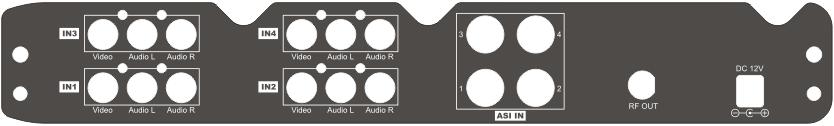
7 CSD 1000B CSD 2000B CSD 4000B 6
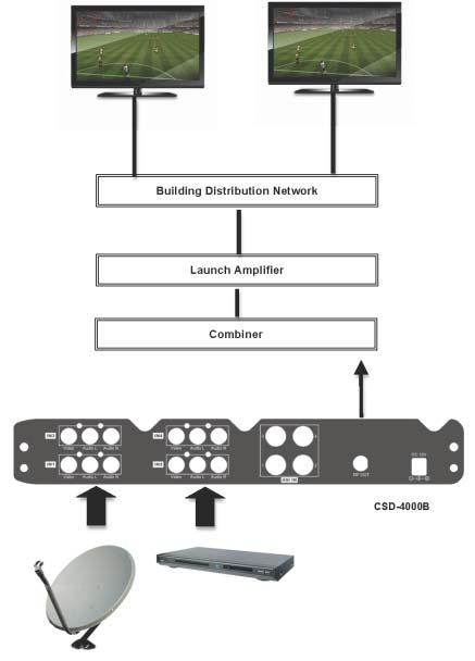
8 HARDWARE INSTALLANTION and CONNECTIONS 1. The unit can be rack mounted in a standard EIA 19 rack. Attach the rack mounts if the unit is to be installed in a rack. 2. Use a 75Ω coaxial cable with RCA connectors to connect the video source (e.g., CATV, DVD, VCR, Camera) to the unit s yellow RCA VIDEO INPUT jack (IN1 IN4 depending on the CSD model). Note: If the ASI input is required then use a cable with a BNC connector between the video source and the ASI IN jack. Repeat this step for each video source connection. It is highly recommended that quality coaxial cable and connectors be used for all video source connections. 3. Use RCA cables to connect the audio source to the red / white AUDIO L and AUDIO R INPUT jacks (IN1 IN4 depending on the CSD model). Use the red and white jacks for audio input or either one for a single input. Repeat this step for each audio source connection. Be sure the video and audio connections for each source are consistent with the unit s inputs (IN1 IN4 depending on the CSD model). It is highly recommended that quality cables and connectors be used for all audio source connections. 4. Use a quality 75Ω coaxial cable with F connectors from the unit s RF OUT jack to the distribution system (combiner or reverse splitter) or directly to a television. 5. Connect the included 12VDC 3A power supply to the unit s DC 12V POWER jack. 6. Connect the 12VDC 3A power supply to an appropriately rated AC power outlet. 7
9 8

10 MODULATOR SETUP AND CONFIGURATION INITIAL SETUP TO FACTORY DEFAULT The CSD s front panel is used to configure the modulator as desired. Before performing a configuration it is advised that the Factory Default settings should be initialized as follows: Power up the device and wait until the booting process is complete. Once complete, press the Scroll Up/Down button until Default Config appears in the menu. After Default Config appears press the OK button. Power down the unit by removing the power supply cable from the DC 12V power jack. Wait 5 seconds and re-connect the power supply. MODULATOR CONFIGURATION Once the modulator is powered back up it will go through an internal booting process. When Running appears in the LCD Display the unit is ready for programming or operation. Password Press the OK button to select a 4-digit password. Use the Scroll Up/Down button to search and select individual numbers for the password. The default password is Press the OK button for each number to set the password. Advanced Menu To access the Advanced Menu first enter the password by pressing the OK button. Once the correct password is entered press the OK button and the LCD Screen will display Advanced Menu Output Channel. The following configuration options are available under Advanced Menu: Output Channel Use the Scroll Up/Down button to change the output channel. Channels 2 to 135 are available. Once the desired output channel is selected press the OK button to set the channel. Attenuation Use the Scroll Up/Down button to select Attenuation. Press the OK button to enter the Attenuation menu. Use the Scroll/Up down button to select the desired attenuation in 1dB increments from 0 to minus 20 db. Once the desired attenuation level is found press the OK button to set. Constellation Use the Scroll Up/Down button to select Constellation. Press the OK button to enter the Constellation menu. The modulator allows for either QAM256 or QAM64. Select the desired Constellation then press the OK button to set. Interleaver Use the Scroll Up/Down button to select Interleaver. Press the OK button to enter the Interleaver menu. Use the Scroll Up/Down button to select the desired Interleaver values then press the OK button to set. Channel Type Use the Scroll Up/Down button to select Channel Type. Press the OK button to enter the Channel Type menu. Menu options are STD, HRC and IRC. The factory default is STD. Use the Scroll Up/Down button to select the desired Channel Type and press the OK button to set. Reserve Factory set and not adjustable. 9
11 RF Output Use the Scroll Up/Down button to select RF Output. Press the OK button to enter the RF Output menu. Menu options are Normal, Inverted and C.W. The factory default is Normal. Use the Scroll Up/Down button to select the desired RF Output and press the OK button to set. Brightness Use the Scroll Up/Down button to select Brightness. Press the OK button to enter the Brightness menu. Use the Scroll Up/Down button to select the desired Brightness value (0 to 255) and press the OK button to set. Factory default is 128 Contrast Use the Scroll Up/Down button to select Contrast. Press the OK button to enter the Contrast menu. Use the Scroll Up/Down button to select the desired Contrast value (0 to 255) and press the OK button to set. Factory default is 128. Saturation Use the Scroll Up/Down button to select Saturation. Press the OK button to enter the Saturation menu. Use the Scroll Up/Down button to select the desired Saturation value (0 to 255) and press the OK button to set. Factory default is 128. Sharpness Use the Scroll Up/Down button to select Sharpness. Press the OK button to enter the Sharpness menu. Use the Scroll Up/Down button to select the desired Sharpness value (0 to 255) and press the OK button to set. Factory default is 64. Hue Use the Scroll Up/Down button to select Hue. Press the OK button to enter the Hue menu. Use the Scroll Up/Down button to select the desired Hue value (0 to 255) and press the OK button to set. Factory default is 128. Device Address Use the Scroll Up/Down button to select Device Address. Press the OK button to enter the Device Address menu. Use the Scroll Up/Down to select the Desired Address ranging from 1 to 32 then press the OK button to set. Reserve Factory set and not adjustable. Stream ID Use the Scroll Up/Down button to select Stream ID. Press the OK button to enter the Stream ID menu. Use the Scroll Up/Down button to select the desired Stream ID ranging from 0 to then press the OK button to set. Factory default is Network ID Use the Scroll Up/Down button to select Network ID. Press the OK button to enter the Network ID menu. Use the Scroll Up/Down button to select the desired Network ID ranging from 0 to then press the OK button to set. Factory default is 100. ORG Network ID Use the Scroll Up/Down button to select ORG Network ID. Press the OK button to enter the ORG Network ID menu. Use the Scroll Up/Down button to select the desired ID ranging from 0 to then press the OK button to set. Factory default is 10. Network Name Use the Scroll Up/Down button to select Network Name. Press the OK button to enter the Network Name menu. Use the Scroll Up/Down button to select the first character for the desired Network Name then press the OK button to set. Repeat the process for each character in the desired Network Name. A Network Name can consist up to 16 characters. Default Configuration If you wish to set the modulator back to the factory default settings use the Scroll Up/Down button to reach Default Configuration then press the OK button. Caution: Once the OK button is pressed the unit will automatically reset to the factory default. LCN Mode Use the Scroll Up/Down button to select LCN Mode. Press the OK button to enter the LCN Mode menu. Use the Scroll Up/Down button to select the desired LCN Mode: APN, EACEM, ITC, NorDig. The factory default is APN. Press the OK button to set. 10
12 1 Video Input Use the Scroll Up/Down button to select 1 Video Input. Press the OK button to enter the 1 Video Input menu. Use the Scroll Up/Down button to select the Video Input option: NTSC, PAL, ASI. The factory default is NTSC. Press the OK button to set. If the modulator has more than one video input scroll through the Advanced Menu for the additional video input menus. 1 Program Num Use the Scroll Up/Down button to select 1 Program Num. Press the OK button to enter the 1 Program Num menu. Use the Scroll Up/Down button to select the desired 1 Program Num option ranging from 0 to then press the OK button to set. Factory default is If the modulator has more than one video input scroll through the Advanced Menu for the additional Program Num menus. 1 Channel Name Use the Scroll Up/Down button to select 1 Channel Name. Press the OK button to enter the 1 Channel Name menu. Use the Scroll Up/Down menu to select the first character of the desired Channel Name then press the OK button to set. Repeat the process until the Channel Name is completed. If the modulator has more than one video input scroll through the Advanced Menu for additional channel name menus. 1 Provider Name Use Scroll Up/Down button to select 1 Provider Name. Press the OK button to enter the 1 Provider Name menu. Use the Scroll Up/Down button to select the first character of the desired 1 Provider Name then press the OK button to set. Repeat the process until the desired Provider Name is completed. If the modulator has more than one video input scroll through the Advanced Menu for additional Provider Name menus. 1 LCN Use the Scroll Up/Down button to select 1 LCN. Press the OK button to enter the 1 LCN menu. Use the Scroll Up/Down button to select the desired LCN value then press the OK button to set. The 1 LCN value range is from 1 to 999. If the modulator has more than one video input scroll through the Advanced Menu for additional LCN menus. 1 Aspect Ratio Use the Scroll Up/Down button to select 1 Aspect Ratio. Press the OK button to enter the 1 Aspect Ratio menu. Use the Scroll Up/Down button to select the desired Aspect Ratio option of 4:3 or 16:9 then press the OK button to set. Factory default is 4:3. If the modulator has more than one video input scroll through the Advanced Menu for additional Aspect Ratio menus. To exit the Advanced Menu use the Scroll Up/Down button to select Exit then press the OK button. Exit Exit Menu will appear on the LCD screen. Press the OK button twice to exit. Once the settings are made and the modulator is programmed (a) remove power from the unit by disconnecting the power supply cable from the DC 12V jack, (b) wait 5 seconds and (c) reconnect the power cable to the unit s DC 12V jack. This will allow the modulator to capture the new settings. 11
13 CSD MODULATOR NOTES PRODUCT NOTES: ITEM VALUE PASSWORD SERIAL NUMBER INSTALLATION DATE PURCHASE DATE VIDEO 1 INPUT VIDEO 2 INPUT VIDEO 3 INPUT VIDEO 4 INPUT 12
DVQ INSTALLATION & CONFIGURATION MANUAL DVQAM-1 / DVQAM-2. Single and Dual Input QAM Encoders / Modulators
 INSTALLATION & CONFIGURATION MANUAL DVQAM-1 / DVQAM-2 Single and Dual Input QAM Encoders / Modulators TABLE OF CONTENTS SAFETY PRECAUTIONS... 3 PACKAGE CONTENTS... 4 PRODUCT DESCRIPTION... 4 SPECIFICATIONS...
RL-DM Input DVB-T Encoder / Modulator User Guide and Install Manual
 ZyCastR Radio Frequency Range digi-mod RL-DM4000+ www.digi-modbyzycast.com RL-DM4000+ 4 Input DVB-T Encoder / Modulator User Guide and Install Manual Table of Contents Safety Precautions 2 Package Contents
User Guide and Install Manual
 digi-mod HD-1605 www.digi-modbyzycast.com HD-1605 Single Input DVB-T HD Digital Modulator with Delayed Audio Output User Guide and Install Manual TABLE OF CONTENTS SAFETY PRECAUTIONS...2 PACKAGE CONTENTS...2
INSTALLATION & CONFIGURATION MANUAL
 INSTALLATION & CONFIGURATION MANUAL FDM-8000i 8-port SD Digital Modulator with IP FDM-8000i Manual V1.0 TABLE OF CONTENTS SAFETY PRECAUTIONS... 3 PACKAGE CONTENTS... 4 PRODUCT DESCRIPTION... 4 SPECIFICATIONS...
User Guide and Install Manual
 digi-mod HD-4797 www.digi-modbyzycast.com HD-4797 4-Input HD Digital Modulator with HDMI Loop Through and IR User Guide and Install Manual TABLE OF CONTENTS SAFETY PRECAUTIONS...2 PACKAGE CONTENTS...2
INSTALLATION & CONFIGURATION MANUAL. HD-1000DM / HD-2000DM / HD-4000 (DVB-T HD Series) Single / Dual / Quad Input Encoders / Modulators
 Single / Dual / Quad Input Encoders / Modulators") INSTALLATION & CONFIGURATION MANUAL HD-1000DM / HD-2000DM / HD-4000 (DVB-T HD Series) Single / Dual / Quad Input Encoders / Modulators TABLE OF CONTENTS SAFETY PRECAUTIONS... 3 PACKAGE CONTENTS... 4 PRODUCT
INSTALLATION & CONFIGURATION MANUAL HD-1000DM / HD-2000DM / HD-4000 (DVB-T HD Series) Single / Dual / Quad Input Encoders / Modulators TABLE OF CONTENTS SAFETY PRECAUTIONS... 3 PACKAGE CONTENTS... 4 PRODUCT
HD-4002DM Quad Input DVB-T HD Encoder / Modulator User Guide and Install Manual
 ZyCastR Radio Frequency Range digi-mod HD-4002DM www.digi-modbyzycast.com HD-4002DM Quad Input DVB-T HD Encoder / Modulator User Guide and Install Manual Table of Contents Safety Precautions... 2 Package
User Manual. Terrestrial DVB-T/T2 to IPTV Converter CT2IP-8032
 User Manual Terrestrial DVB-T/T2 to IPTV Converter CT2IP-8032 ZyCast Technology Inc. No. 33, Lane 181, Chung Hwa Road Section 4, Hsin Chu, Taiwan 30060 Tel: +886-3-5400-949 Fax: +886-3-5400-413 E-mail:
User Guide and Installation Manual
 User Guide and Installation Manual HDME102 / HDME202 / HDME402 Single / Dual / Quad Input QAM Encoder / Modulator 1 HDME102/202/402 Manual V1.0 Table of Contents Safety Precautions...3 Package Contents...3
INSTALLATION & CONFIGURATION MANUAL. resi-linx RL-IP1000 HD IP Streaming Server
 INSTALLATION & CONFIGURATION MANUAL resi-linx RL-IP1000 HD IP Streaming Server TABLE OF CONTENTS SAFETY PRECAUTIONS...2 PACKAGE CONTENTS...2 PRODUCT DESCRIPTION...3 SPECIFICATIONS...4 INSTALLATION, UNPACKING
SD ENCODER AND MODULATOR YPbPr & CVBS TO DVB-T DIGITAL RF SD4250 USER MANUAL
 SD ENCODER AND MODULATOR YPbPr & CVBS TO DVB-T DIGITAL RF SD4250 USER MANUAL All-in-one encoder and modulator for dual SD source. Allows 4 sets of Audio/Video source to be extended throughout a traditional
Encoder / Modulators
 Encoder / Modulators Contents 03 Package Contents 04 Features 05 Introduction 06 Installation 07 Specifications 09 Visual Identification Illustrations 10 Encoder Programming and Setup via GUI Interface
USER GUIDE AND MANUAL. Dual Input HD Digital Encoder-Modulator with ASI. MODEL: DT-IPTV-QAM-ASI-2H Version 1.0 Last Update:
 USER GUIDE AND MANUAL Dual Input HD Digital Encoder-Modulator with ASI MODEL: DT-IPTV-QAM-ASI-2H Version 1.0 Last Update: 01-15-2019 DT-IPTV-QAM-ASI-2H Manual V1.0 01152019 NACE Brands is the leading brand
NDS3524 DVB-T SD&HD Encoder & Modulator with USB. --- Home Use. User Manual
 NDS3524 DVB-T SD&HD Encoder & Modulator with USB --- Home Use User Manual Thank you for buying this encoder modulator. Please read this manual carefully to install, use and maintain the encoder modulator
HD ENCODER AND MODULATOR HDMI TO DVB-T DIGITAL RF (MPEG-4) 14MM-DM05 USER MANUAL 3-14
 14MM-DM05 USER MANUAL 3-14") HD ENCODER AND MODULATOR HDMI TO DVB-T DIGITAL RF (MPEG-4) 14MM-DM05 USER MANUAL 3-14 PRODUCT INTRODUCTION Indicator LCD Window Control Buttons RF out RF mix in USB Port for Upgrade HDMI in DC 12V Grounding
HD ENCODER AND MODULATOR HDMI TO DVB-T DIGITAL RF (MPEG-4) 14MM-DM05 USER MANUAL 3-14 PRODUCT INTRODUCTION Indicator LCD Window Control Buttons RF out RF mix in USB Port for Upgrade HDMI in DC 12V Grounding
HDM-500T. DVB-T HD Encoder & Modulator
 HDM-500T DVB-T HD Encoder & User Manual Thank you for buying this encoder modulator. Please read this manual carefully to install, use and maintain the encoder modulator in the best conditions of performance.
Marshall Lynx LCD Universal Monitors
 Marshall Lynx LCD Universal Monitors User Manual Marshall Industrial Video/Security Div. For more information, contact Marshall Electronics, Industrial Video & Security (800) 800-6608 www.mars-cam.com
INSTALLATION MANUAL. ST-BT1000IR2812-G Varifocal IR Bullet Camera. v1.0 8/4/14 1
 INSTALLATION MANUAL ST-BT1000IR2812-G Varifocal IR Bullet Camera v1.0 8/4/14 1 This package contains: PACKAGE CONTENTS One ST-BT1000IR2812-G varifocal infrared bullet color camera Mounting Hardware One
1 HDMI & YPbPr, CVBS Digital RF Encoder Modulator. User Manual B-QAM-HDMI-1CH
 1 HDMI & YPbPr, CVBS Digital RF Encoder Modulator User Manual B-QAM-HDMI-1CH Thank you for buying this encoder modulator. Please read this manual carefully to install, use and maintain the encoder modulator
SUBWOOFER SYSTEM YST-MSW10
 ACTIVE SERVO PROCESSING SUBWOOFER SYSTEM YST-MSW10 Active Servo SUBWOOFER SYSTEM YST-MSW10 Active Servo HIGH CUT HIGH LOW OWNER S MANUAL MANUAL DE INSTRUCCIONES CAUTION RISK OF ELECTRIC SHOCK DO NPT OPEN
YST-SW20 SUBWOOFER SYSTEM OWNER S MANUAL. Active Servo Technology
 CAUTION SUBWOOFER SYSTEM Active Servo RISK OF ELECTRIC SHOCK DO NOT OPEN CAUTION: TO REDUCE THE RISK OF ELECTRIC SHOCK DO NOT REMOVE COVER (OR BACK). NO USER-SERVICEABLE PARTS SIDE. REFER SERVICG TO QUALIFIED
TVA2.1 2-Channel Digital Amplifier Installation Manual
 TVA2.1 2-Channel Digital Amplifier Installation Manual SAFETY INSTRUCTIONS WARNING: TO REDUCE THE RISK OF FIRE OR ELECTRIC SHOCK, DO NOT EXPOSE THIS APPLIANCE TO RAIN OR MOISTURE. CAUTION: TO REDUCE THE
USER MANUAL. For XLCD17-LED XLCD19-LED
 USER MANUAL For XLCD17-LED XLCD19-LED 2 TABLE OF CONTENTS CE information ------------------------------------------------------------------------ 4 Safety Precautions -------------------------------------------------------------------
HDMI 1x2 Splitter B-230-HDSPLTR-1x2 INSTALLATION MANUAL HDMI OUT 2 HDMI OUT 1 B-230-HDSPLTR-1X2 POWER HDMI IN
 HDMI OUT 2 HDMI 1x2 Splitter B-230-HDSPLTR-1x2 INSTALLATION MANUAL B-230-HDSPLTR-1X2 HDMI OUT 1 POWER HDMI IN IMPORTANT SAFETY INSTRUCTIONS 1. Read and follow all instructions and warnings in this manual.
Cantata m100 Amplifier
 Cantata m100 Amplifier Getting Started Guide www.resolutionaudio.com +1.415.553.4100 Safety Information CAUTION RISK OF ELECTRICAL SHOCK DO NOT OPEN CAUTION: TO REDUCE THE RISK OF ELECTRICAL SHOCK, DO
ST-HD-TD W Varifocal IR Color HD-CVI Camera
 ST-HD-TD2812-720-W Varifocal IR Color HD-CVI Camera V1.0 04/24/14 1 PACKAGE CONTENTS This package contains: One (1) ST-HD-TD2812-720-W varifocal infrared turret-dome color HD camera One (1) installation
Downloaded from manuals search engine
 INDEX 1. DVR Features...1 2. Layout 2.1 Front Panel...1 2.2 Rear Panel...2 2.3 Remote Control...2 3. Installation 3.1 Installing the Hard Drive...3 3.2 Connecting Camera and Monitor...3 3.3 Connecting
PS8 - II. Professional Power Sequencer. User s Manual
 PS8 - II Professional Power Sequencer User s Manual IMPORTANT SAFETY INSTRUCTIONS READ FIRST This symbol, whenever it appears, alerts you to the presence of uninsulated dangerous voltage inside the enclosure.
INSTALLATION MANUAL. HDMI 1x4 Splitter B-230-HDSPLTR-1x4. B-230-HDSPLTR-1x4 HDMI OUT 4 HDMI OUT 3 HDMI OUT 2 HDMI OUT 1 HDMI OUT 4 HDMI IN
 HDMI 1x4 Splitter B-230-HDSPLTR-1x4 INSTALLATION MANUAL HDMI OUT 4 HDMI OUT 3 HDMI OUT 2 HDMI OUT 1 HDMI OUT 1 B-230-HDSPLTR-1x4 HDMI OUT 2 HDMI OUT 3 HDMI OUT 4 HDMI IN HDMI IN 2 IMPORTANT SAFETY INSTRUCTIONS
VPC-64/ VPX-64 VIDEO POLE CAMERA OPERATION MANUAL
 VPC-64/ VPX-64 VIDEO POLE CAMERA OPERATION MANUAL RESEARCH ELECTRONICS INTERNATIONAL 455 Security Drive Algood, TN 38506 U.S.A. +1 931-537-6032 http://www.reiusa.net/ COPYRIGHT RESEARCH ELECTRONICS INTERNATIONAL
HSC-42. HDMI 4k2k Video Up/Down Scaler
 INSTRUCTION MANUAL HSC-42 HDMI 4k2k Video Up/Down Scaler SAFETY AND NOTICE 1. Read these instructions. 2. Keep these instructions. 3. Heed all warnings. 4. Follow all instructions. 5. Do not use this apparatus
INSTALLATION MANUAL. HDMI 1x8 Splitter B-230-HDSPLTR-1x8 B-230-HDSPLTR-1X8
 HDMI 1x8 Splitter B-230-HDSPLTR-1x8 INSTALLATION MANUAL HDMI OUT 8 HDMI OUT 7 HDMI OUT 6 HDMI OUT 5 HDMI OUT 4 HDMI OUT 3 HDMI OUT 2 HDMI OUT 1 B-230-HDSPLTR-1X8 HDMI OUT 1 HDMI OUT 2 +5 VDC HDMI OUT 3
LevelOne. KVM-0115/KVM / 17-inch LCD KVM Rack Console. User Manual. Version
 LevelOne KVM-0115/KVM-0117 15 / 17-inch LCD KVM Rack Console User Manual Version 1.0-1305 1 SAFETY INSTRUCTIONS 1. Please read these safety instructions carefully. 2. Please keep this User Manual for later
9.2 TFT LCD COLOR MONITORING SYSTEM With 2 Indoor/Outdoor Color Cameras
 INSTRUCTION MANUAL 9.2 TFT LCD COLOR MONITORING SYSTEM With 2 Indoor/Outdoor Color Cameras MODEL: LCD0935 Copyright 2009 Wisecomm. All Rights Reserved. 1. IMPORTANT SAFETY PRECAUTIONS To prevent fire or
CS-1 Active Full Range Integrated Commercial Audiovisual System
 Active Full Range Integrated Commercial Audiovisual System User Manual SAFETY INSTRUCTIONS PLEASE READ THROUGH THIS MANUAL FIRST BEFORE OPERATING THE CS-1 SYSTEM. Thank you for purchasing this Beta3 product
VeCOAX. Micromod MS REFERENCE GUIDE
 VeCOAX Micromod MS Advanced Wall Mount HD Video Modulator REFERENCE GUIDE 2014 Advanced model with also USB Recording and PLAY Capabilities, 1080P input over both mpeg2 and mpeg4 modes, low latency encoding
BS 181 SINGLE CHANNEL POWER SUPPLY USER MANUAL
 BS 181 SINGLE CHANNEL POWER SUPPLY USER MANUAL Issue 2011 ASL Intercom BV DESIGNED & MANUFACTURED BY: ASL Intercom B.V. Zonnebaan 42 3542 EG Utrecht The Netherlands Tel: +31 (0)30 2411901 Fax: +31 (0)30
U-150 Integrated Amplifier User s guide
 U-150 Integrated Amplifier User s guide U-150 Integrated Amplifier User s guide Specifications: Contents: Output: Phono: Line: Digital: Volume control: Dimensions: Weight: 2 300W/8 Ohm, 2 600W/4 Ohm Distortion:
DS-1H05 Ethernet-over-Coax Extender. User Manual
 DS-1H05 Ethernet-over-Coax Extender User Manual Thank you for purchasing our product. If there is any question or request, please do not hesitate to contact dealer. This manual is applicable to DS-1H05-T,
WARNINGS AND PRECAUTIONS... 3 PACKING LIST... 5 FRONT PANEL... 5 REAR PANEL... 6 MENU SETTINGS... 7 EXAMPLE SETUP SPECIFICATIONS...
 AUDIO DELAY sax AD-1 aam Quick Start Guide WARNINGS AND PRECAUTIONS... 3 PACKING LIST... 5 FRONT PANEL... 5 REAR PANEL... 6 MENU SETTINGS... 7 EXAMPLE SETUP... 11 SPECIFICATIONS... 11 SERVICE & SUPPORT...
IPS11& IPS12_2016V1.1
 User Manual IPS11& IPS12 HDMI Streaming Transmitter& Receiver All Rights Reserved Version: IPS11& IPS12_2016V1.1 HDMI Streaming Transmitter& Receiver Statement Read this user manual carefully before using
T L Audio INDIGO SERIES. User Manual PA-2001 VALVE PRE-AMPLIFIER. Tony Larking Professional Sales Limited, Letchworth, England.
 T L Audio INDIGO SERIES User Manual PA-2001 VALVE PRE-AMPLIFIER Tony Larking Professional Sales Limited, Letchworth, England. Tel: 01462 490600. International +44 1462 490600. Fax: 01462 490700. International
OLi POWA-5 Active Monitors
 Active Monitors User Manual : English Contents Important Information... 3 Front & Rear Panels... 4 Remote Control... 5 Connecting Your Speakers... 6 Bluetooth Function... 7 Use with ipod / MP3... 8 Use
LevelOne KVM User Manual. 17 Modularized KVM Console V
 LevelOne KVM-0217 17 Modularized KVM Console User Manual V1.0.0-0708 SAFETY INSTRUCTIONS 1. Please read these safety instructions carefully. 2. Please keep this User Manual for later reference. 3. Please
OWNER S MANUAL CD-2 V 1.3
 OWNER S MANUAL CD-2 V 1.3 2 TABLE OF CONTENTS WARNINGS... 3 ACCESSORIES... 4 REMOTE CONTROL... 5 FRONT PANEL... 6 REAR PANEL... 7 MENU SYSTEM... 8 NOTES OF IMPORTANCE... 10 CONNECTORS... 11 TECHNICAL SPECIFICATIONS...
Active UTP Transceiver Hub with Integral Isolated Camera Power
 Active UTP Transceiver Hub with Integral Isolated Installation Guide HubWayEX16SP - UL Listed sixteen (16) Channel Active UTP Transceiver Hub with Integral Isolated Rev. 011810 More than just power. TM
User Manual. Stoltzen SHSP14 HDMI Splitter 1x4. 4K HDMI Splitter 1x4. All Rights Reserved. Version: SHSP14_2016V2
 User Manual 4K HDMI Splitter 1x4 All Rights Reserved Version: SHSP14_2016V2 SAFETY PRECAUTIONS To insure the best from the product, please read all instructions carefully before using the device. Save
It s Under Control. Installation and Operation Guide CPB-1. Control Port Connecting Block V 1.1
 Installation and Operation Guide 70-210043-17 V 1.1 Copyright 2008 Remote Technologies Incorporated All rights reserved. 2 DECLARATIONS 117 612 914 DECLARATION OF CONFORMITY (DOC) The Declaration of Conformity
IMPORTANT SAFETY INSTRUCTIONS
 IMPORTANT SAFETY INSTRUCTIONS When using this electronic device, basic precautions should always be taken, including the following: 1. Read all instructions before using the product. 2. Do not use this
User Manual SP2H2A-H2. HDMI 2.0 1x2 Splitter with Audio Breakout. All Rights Reserved. Version: SP2H2A-H2_2018V1.0
 User Manual SP2H2A-H2 All Rights Reserved Version: SP2H2A-H2_2018V1.0 Preface Read this user manual carefully before using the product. Pictures are shown in this manual for reference only. Different models
SERVICE MANUAL 1/3 SONY DSP COLOR CCD CAMERA OVER 650TVL SERIES
 SERVICE MANUAL 1/3 SONY DSP COLOR CCD CAMERA OVER 650TVL SERIES The serial number of this product may be found on the bottom of the unit. You should note the serial number of this unit in the space provided
Monochrome Camera. Features. User manual
 Monochrome Camera LTC0330/11 LTC0330/21 LTC0350/11 LTC0350/21 LTC0330/51 LTC0330/61 LTC0350/51 LTC0350/61 Features To obtain the best results from your new camera, read these instructions carefully before
5 B&W Rear View System Camera
 5 B&W Rear View System Camera Instruction Manual MODEL: CA453 www.lorexcctv.com Copyright 2007 LOREX Technology Inc. Thank you for purchasing the Lorex 5 Black & White Rear View System Camera. This system
User Manual SP2-4K. 4K HDMI Splitter 1x2. All Rights Reserved. Version: SP2-4K_2016V1.0
 User Manual SP2-4K 4K HDMI Splitter 1x2 All Rights Reserved Version: SP2-4K_2016V1.0 SAFETY PRECAUTIONS To insure the best from the product, please read all instructions carefully before using the device.
On-Line CardioTheater Instruction Manual for Amplifier Models 800 and 1600 (wired)
") On-Line CardioTheater Instruction Manual for Amplifier Models 800 and 1600 (wired) Full installation instructions accompany your Cardio Theater equipment order. This On-Line version of our Installation/Instruction
On-Line CardioTheater Instruction Manual for Amplifier Models 800 and 1600 (wired) Full installation instructions accompany your Cardio Theater equipment order. This On-Line version of our Installation/Instruction
Wide Dynamic Range Dome Camera WDR-D3
 Wide Dynamic Range Dome Camera WDR-D3 200 New Highway Amityville, NY 11701 631-957-8700 www.specotech.com Please read this manual thoroughly before operation and keep it handy for further reference. WARNING
EN-264 DVB MPEG-4 HDTV ENCODER & TRANSCODER - 0 MI1720 -
 EN-264 DVB MPEG-4 HDTV ENCODER & TRANSCODER - 0 MI1720 - SAFETY NOTES Read the user s manual before using the equipment, mainly " SAFETY RULES " paragraph. The symbol on the equipment means "SEE INSTRUCTION
Audio Zone Amplifier 2 x 20 watts Installation Guide
 2 x 20 watts 500216 MuxLab Inc. 2015 94-000805-A / SE-000805-A SAFETY PRECAUTIONS To insure the best from the product, please read all instructions carefully before using the device. Save this manual for
AUD-220 Installation Guide
 AUD-220 Installation Guide STEREO MONO BRIDGE IR RS232 TX RX MIC 48V LINE L R MIC 1 2 INPUTS 24V DC 1 x 40W @ 8Ω 2 x 20W @ 4Ω LOOP OUTPUTS The Intelix AUD-220 is a 2x20 watt Class D amplifier with 8Ω speaker
USERS GUIDE ASP-18H-4K. HDMI 4K2K 1x8 Splitter with EDID Management. Manual Number:
 USERS GUIDE ASP-18H-4K HDMI 4K2K 1x8 Splitter with EDID Management i Manual Number: 141110 SAFETY INSTRUCTIONS Please review the following safety precautions. If this is the first time using this model,
ACCESSORY 2 - MONITOR INSTRUCTION MANUAL
 8.5" LCD WIDESCREEN MONITOR with 2 Camera AV Inputs ACCESSORY - MONITOR SVAT ELECTRONICS INSTRUCTION MANUAL Version 1.1 Model# CLEARVU7 www.svat.com !IMPORTANT! PLEASE READ! SVAT ELECTRONICS NEED HELP?
OPERATING INSTRUCTIONS PA AMPLIFIER P-1812
 OPERATING INSTRUCTIONS PA AMPLIFIER P-1812 Please follow the instructions in this manual to obtain the optimum results from this unit. We also recommend that you keep this manual handy for future reference.
PREMIUMAUDIOVIDEOLIGHTINGANDPOWERPRODUCTS
 FACTOR ELECTRONICS PREMIUMAUDIOVIDEOLIGHTINGANDPOWERPRODUCTS V-RVC Owners Manual IMPORTANT NOTE: THIS OWNER'S MANUAL IS PROVIDED AS AN INSTALLATION AND OPERATING AID. FACTOR ELECTRONICS DOES NOT ASSUME
TABLE OF CONTENTS ADJUSTING YOUR LCD MONITOR
 TABLE OF CONTENTS ADJUSTING YOUR LCD MONITOR -------------- 2 General safety precautions. 2 Unpacking your monitor 5 Viewing angle 6 How to open the back cover 6 Connecting your monitor 7 User controls
C-300 Preamplifier User s guide
 C-300 Preamplifier User s guide C-300 Preamplifier User s guide Specifications: Contents: Output: Max 7.5Vrms unbalanced (RCA) or 15Vrms balanced (XLR) SPECIFICATIONS Page 2 Phono: istortion, line stage:
DVI KVM. Extra Long Range Extender Over One CAT5. User Manual EXT-DVIKVM-ELR. Release A8
 DVI KVM Extra Long Range Extender Over One CAT5 EXT-DVIKVM-ELR User Manual Release A8 Important Safety Instructions 1 Read these instructions 2 Keep these instructions 3 Heed all warnings 4 Follow all
Azimut. Minimalist design, maximum connectivity. Reference Guide
 Minimalist design, maximum connectivity Complete audio solution with plug and play capabilities Bluetooth connectivity Onboard Spotify Dedicated app via Wi-F Thank you for choosing a K-array product! To
DAB A d a pt e r 3+ Dear Customer,
 Dear Customer, Quality has always been our driving force and founding Argon Audio is a natural extension of this philosophy. We have 20 years' experience in creating and specifying high quality products,
Rack Mount Power Supplies
 Rack Mount Power Supplies Installation Guide Models Include: VertiLine33D - 12VDC @ 8A - Sixteen (16) PTC protected outputs VertiLine33TD - 12VDC @ 16A - Sixteen (16) PTC protected outputs VertiLine63D
VMC-8114P VMC-8414P INSTRUCTION MANUAL. Colour Video Monitor
 STRUCTION MANUAL VMC-8114P VMC-8414P Colour Video Monitor About this manual Before installing and using this unit, please read this manual carefully. Be sure to keep it handy for later reference. This
SMART Hi-Fi AUDIO *MFL * SJ8 SIMPLE MANUAL. Wireless Multi-room Sound Bar
 ENGLISH SIMPLE MANUAL SJ8 SMART Hi-Fi AUDIO Wireless Multi-room Sound Bar Please read this manual carefully before operating your set and retain it for future reference. To view the instructions of advanced
WARNING! CAUTION: TO REDUCE THE RISK OF ELECTRIC SHOCK, DO NOT REMOVE THE COVER OF THIS UNIT. THERE ARE NO USER
 PTA44BT 4 Channel Audio Amplifier Multi-Source 1/4 Audio/Microphone inputs MP3/USB/SD Readers/ FM radio, Built-in Wireless BT Audio Streaming (500 Watts) WARNING! CAUTION: TO REDUCE THE RISK OF ELECTRIC
DVAA Series Disk Array for DVR1 Series Digital Video Recorder
 DVAA Series Disk Array for DVR1 Series Digital Video Recorder Eng Installation Instructions Philips Communication, Security & Imaging Warning! To prevent fire and electronic shock, do not expose this product
SRD x DVB- S/S2 SD/HD Decoder
 SRD 8000 4x DVB- S/S2 SD/HD Decoder TABLE OF CONTENTS 1. SAFETY INSTRUCTION... 4 2. Overview... 5 3. Technical Specification... 6 3.1. Input Port... 7 3.2. Output Port... 7 4. Equipment composition...
USER MANUAL. User Manual 17 / 19 LCD. NVP117 / NVP119 1U LCD Console Drawer. Options : - AV / DVI-D / HDMI / Audio - Full Range KVM - DC power
 USER MANUAL 17 / 19 LCD NVP117 / NVP119 1U LCD Console Drawer Options : - AV / DVI-D / HDMI / Audio - Full Range KVM - DC power Contents < Part. 1 > NVP117 / NVP119 1.1 Package Content 1.2 Structure Diagram
User Manual. Rack Mount Display Monitor RMP-161-F17A. 6U 17.3 inch Rack Mount Display Monitor. Options : - AV, S-video input - Touchscreen
 User Manual Rack Mount Display Monitor RMP-161-F17A 6U 17.3 inch Rack Mount Display Monitor Options : - AV, S-video input - Touchscreen Contents < Part. 1 > RMP-161-F17A 1.1 Package Content 1.2 Structure
KS-SB200 BOOM BOX INSTRUCTIONS LVT B [J]
![KS-SB200 BOOM BOX INSTRUCTIONS LVT B [J]](/thumbs/72/66806114.jpg "KS-SB200 BOOM BOX INSTRUCTIONS LVT B [J]") BOOM BOX KS-SB200 INSTRUCTIONS For Customer Use: Enter below the Model No. and Serial No. which are located either on the rear, bottom or side of the cabinet. Retain this information for future reference.
BOOM BOX KS-SB200 INSTRUCTIONS For Customer Use: Enter below the Model No. and Serial No. which are located either on the rear, bottom or side of the cabinet. Retain this information for future reference.
PREMIUMAUDIOVIDEOANDPOWERPRODUCTS V-RVC-PRO. Owners Manual
 PREMIUMAUDIOVIDEOANDPOWERPRODUCTS V-RVC-PRO Owners Manual IMPORTANT NOTE: THIS OWNER'S MANUAL IS PROVIDED AS AN INSTALLATION AND OPERATING AID. FACTOR ELECTRONICS DOES NOT ASSUME ANY RESPONSIBILITY AS
OWNER S MANUAL GEQ 131/ 131LF GEQ 215/ 215LF GEQ 231. Single Channel 31 Band Graphic Equalizer. 2 Channel 15 Band Graphic Equalizer
 20 25 31.5 40 50 63 80 0 125 160 200 250 315 400 500 630 800 1K 1.25K 1.6K 2K 2.5K 3.15K 4K 5K 6.3K 8K K 12.5K 16K 20K +12 +6 +3 0-3 GEQ 131LF 5 31 BAND GRAPHIC EQUALIZER 15 40 60 7K 15K 22K BYPASS RANGE
Model 7705 Control Module
 www.keithley.com Model 7705 Control Module User s Guide PA-696 Rev. D / October 2006 A G R E A T E R M E A S U R E O F C O N F I D E N C E Safety Precautions The following safety precautions should be
AUD-340 Installation Guide
 F0123456789ABC DE AUD-340 Installation Guide INPUTS CONTROL OUTPUT 24V DC 48V LINE 2 AUDIO IR RS232 COM 70V 100V 1 3 DIGITAL L R AUDIO 2.5A MAX TX RX 1 2 3 INPUT SELECT LINE BASS TREBLE MUTE 1 Safety Precautions
BS 181 SINGLE CHANNEL POWER SUPPLY USER MANUAL
 BS 181 SINGLE CHANNEL POWER SUPPLY USER MANUAL August 2016 This product is designed and manufactured by: ASL Intercom B.V. Zonnebaan 42 3542 EG Utrecht The Netherlands Phone: +31 (0)30 2411901 Fax: +31
OWNER S MANUAL SINGLE CAT5E/6 3D EXTENDER B-320-1CAT-HDIR
 OWNER S MANUAL SINGLE CAT5E/6 3D EXTENDER B-320-1CAT-HDIR IMPORTANT SAFETY INSTRUCTIONS WARNING: To reduce the risk of fire or electric shock, do not expose this apparatus to rain or moisture. 1. Read
HD View 12 Plus and HD View 6
 HD View 12 Plus and HD View 6 Component Video & Audio Distribution Amplifier OPERATING INSTRUCTIONS TM TM Using the HD View 12 Plus and HD View 6. Component Video & Audio Distribution Amplifier. Page 2
ST-PTZ High-Speed Intelligent Dome PTZ Color Camera
 INSTALLATION MANUAL ST-PTZ550-27 High-Speed Intelligent Dome PTZ Color Camera Copyright North American Cable Equipment, Inc. 1 PACKAGE CONTENTS This package contains: One ST-PTZ550-27 high-speed intelligent
PORTABLE WIRELESS PA SYSTEM WITH LITHIUM -ION RECHARGEABLE BATTERY AWP6042 OWNER S MANUAL. Handheld Microphone Headset Transmitter
 PORTABLE WIRELESS PA SYSTEM WITH LITHIUM -ION RECHARGEABLE BATTERY AWP6042 OWNER S MANUAL X1 Headset Microphone AWX6042H VHF Wireless Headset Transmitter Handheld Microphone Headset Transmitter Thank you
Classic Kiosk. User Guide. Before operating the unit, please read this manual thoroughly, and retain it for future reference
 User Guide Before operating the unit, please read this manual thoroughly, and retain it for future reference Notice 1. When disconnecting the display from an electrical outlet, the plug must be pulled
USER S GUIDE V: For the most up-to-date version of this User s Guide, go to
 USER S GUIDE V:1103-0208-10 For the most up-to-date version of this User s Guide, go to www.gpx.com Warnings and Precautions Important Safety Instructions 1. Read these Instructions. 2. Keep these Instructions.
INSTALLATION MANUAL. ST-BTWD650IR2812 B or W Weatherproof Day/Night Infrared Color Camera
 INSTALLATION MANUAL ST-BTWD650IR2812 B or W Weatherproof Day/Night Infrared Color Camera PACKAGE CONTENTS This package contains: One ST-BTWD650IR2812 camera with Black or White housing One extension tube
B&W RearView Camera Installation & Operation
 B&W RearView Camera Installation & Operation CA52 (Camera) FOR MORE INFORMATION WWW.STRATEGICVISTA.COM BEFORE OPERATING THIS SYSTEM, PLEASE READ THIS MANUAL THOROUGHLY AND RETAIN IT FOR FUTURE REFERENCE
5.6 Color Rear View Safety System Installation & Operation. RV56 (Includes MO56 monitor & CA56 camera)
") 5.6 Color Rear View Safety System Installation & Operation RV56 (Includes MO56 monitor & CA56 camera) FOR MORE INFORMATION WWW.STRATEGICVISTA.COM BEFORE OPERATING THIS SYSTEM, PLEASE READ THIS MANUAL THOROUGHLY
5.6 Color Rear View Safety System Installation & Operation RV56 (Includes MO56 monitor & CA56 camera) FOR MORE INFORMATION WWW.STRATEGICVISTA.COM BEFORE OPERATING THIS SYSTEM, PLEASE READ THIS MANUAL THOROUGHLY
Document Part Number: Rev. 01 (December 2009) TouchTunes and the TouchTunes logo are trademarks of TouchTunes Interactive Networks.
 TouchTunes and the TouchTunes logo are trademarks of TouchTunes Interactive Networks.") Document Part Number: 9002211-001 Rev. 01 (December 2009) Disclaimer TouchTunes and the TouchTunes logo are trademarks of TouchTunes Interactive Networks. All other brand and product names are trademarks
Document Part Number: 9002211-001 Rev. 01 (December 2009) Disclaimer TouchTunes and the TouchTunes logo are trademarks of TouchTunes Interactive Networks. All other brand and product names are trademarks
FOOT CONTROLLER FCV100
 CV NORM OUTPUT2 OUTPUT1 MIN VOL 0 10 User Manual FOOT CONTROLLER FCV100 Ultra-Flexible Dual-Mode Foot Pedal for Volume and Modulation Control 2 FOOT CONTROLLER FCV100 User Manual Table of Contents Thank
EA014 Whiteboard Speakers. Manual and installation instructions
 EA014 Whiteboard Speakers Manual and installation instructions Thank you for buying this product. We are confident it will provide you with a long reliable service, but just in case you experience a problem,
Active UTP Transceiver Hub with Integral Camera Power Installation Guide
 Active UTP Transceiver Hub with Integral Installation Guide Models Include: HubWayLD8CDS - UL Listed eight (8) Channel Active UTP Transceiver Hub with Integral HubWayLD82CDS - UL Listed eight (8) Channel
LIFESTYLE ROOMMATE POWERED SPEAKER SYSTEM. Owner s Guide Guía de usuario Notice d utilisation
 LIFESTYLE ROOMMATE POWERED SPEAKER SYSTEM Owner s Guide Guía de usuario Notice d utilisation TAB 8 TAB 7 TAB 6 TAB 5 TAB 4 TAB 3 TAB 2 English SAFETY INFORMATION Please read this owner s guide Please take
RTT98 VINTAGE TURNTABLE
 RTT98 VINTAGE TURNTABLE WARNING: TO PREVENT FIRE OR SHOCK HAZARD, DO NOT EXPOSE THIS APPLIANCE TO RAIN OR MOISTURE. DO NOT REMOVE COVER. PILOT LAMPS SOLDERED IN PLACE. NO USER SERVICEABLE PARTS INSIDE.
User s Guide. Combo DVR. Thank you for purchasing our product. Please read this User s Manual before using the product. Change without Notice
 Thank you for purchasing our product. Please read this User s Manual before using the product. Change without Notice Combo DVR User s Guide User please operate according to the DVR model that you purchased
8 Button RS232/IR. Control Panel. MuxLab Inc A / SE A
 8 Button RS232/IR Control Panel 500816 MuxLab Inc. 2016 94-000833-A / SE-000833-A SAFETY PRECAUTIONS To insure the best use from the product, please read all instructions carefully before using the device.
PCM60A 100W MAX P.A. AMPLIFIER.
 PCM60A 100W MAX P.A. AMPLIFIER www.pyleaudio.com IMPORTANT SAFETY INSTRUCTIONS 1. Read Instructions All the safety and operating instructions should be read before the appliance is operated. 2. Retain