FCC Part 15 Subpart C Test Report
|
|
|
- Darlene O’Connor’
- 6 years ago
- Views:
Transcription
1 Report No. : UL CE/FCC002-5 Page 1 of 128 FCC Part 15 Subpart C Test Report for DSSS System Product Name : GNSS receiver Model Name : i80 WXYZ Prepared for: Shanghai Huace Navigation Technology LTD. Building C, 599 Gaojing Road, Qingpu District, Shanghai TEL: FAX: Prepared by: Unilab (Shanghai) Co., Ltd FCC register number is No.1350, Lianxi Rd. Pudong New District, Shanghai, China TEL: FAX: Report Number : UL CE/FCC002-4 Date of Report : Date of Test : ~ Notes: The test results only relate to these samples which have been tested. Partly using this report will not be admitted unless been allowed by Unilab. Uniab is only responsible for the complete report with the reported stamp of Unilab.


2 Report No. : UL CE/FCC002-5 Page 2 of 128 Applicant: Shanghai Huace Navigation Technology LTD. Building C, 599 Gaojing Road, Qingpu District, Shanghai Manufacturer: Product Name: Shanghai Huace Navigation Technology LTD. Building C, 599 Gaojing Road, Qingpu District, Shanghai GNSS receiver Brand Name: Model Name: i80 WXYZ Model Description: See Part1.1 Note. FCC ID: Serial Number: EUT Voltage: SY4-A01004 N/A MIN: 8V, NOR:12V, MAX: 36V Date of Receipt: Test Standard: Test Result: FCC CFR Tile 47 Part 15 Subpart C ANSI C 63.4: 2009 KDB D01 v03r03 PASS Date of Test: ~ Tested by : (Test Engineer: Jeffrey Wang) Reviewed by : (Senior Engineer: Forest Cao) Approved by : (Supervisor: Eva Wang)
3 Report No. : UL CE/FCC002-5 Page 3 of 128 TABLE OF CONTENTS 1. GENERAL INFORMATION EUT DESCRIPTION TEST MODE TEST METHODOLOGY EUT CONFIGURATION EUT EXERCISE GENERAL TEST PROCEDURES FCC PART RESTRICTED BANDS OF OPERATIONS DESCRIPTION OF TEST MODES TECHNIACL SUMMARY SUMMARY OF STANDARDS AND TEST RESULTS TEST UNCERTAINTY TEST EQUIPMENT LIST TEST FACILITY TEST SETUP CONFIGURATION OCCUPIED BANDWIDTH TEST SETUP LIMITS TEST PROCEDURE TEST RESULTS DB BANDWIDTH TEST SETUP LIMITS TEST PROCEDURE RESULTS & PERFORMANCE POWER SPECTRAL DENSITY TEST SETUP LIMITS TEST PROCEDURE RESULTS & PERFORMANCE PEAK OUTPUT POWER (CONDUCTION) TEST SETUP LIMITS TEST PROCEDURE RESULTS & PERFORMANCE SPURIOUS EMISSIONS (CONDUCTION) TEST SETUP LIMITS TEST PROCEDURE RESULTS & PERFORMANCE BAND EDGE MEASUREMENT TEST SETUP LIMITS TEST PROCEDURE RESULTS & PERFORMANCE SPURIOUS EMISSIONS (RADIATION) TEST SETUP... 83
4 Report No. : UL CE/FCC002-5 Page 4 of LIMITS TEST PROCEDURE RESULTS & PERFORMANCE AC POWER LINE CONDUCTED EMISSIONS TEST SETUP LIMITS TEST PROCEDURE RESULTS & PERFORMANCE APPENDIX 1 PHOTOGRAPHS OF TEST SETUP APPENDIX 2 PHOTOGRAPHS OF EUT
5 Report No. : UL CE/FCC002-5 Page 5 of GENERAL INFORMATION 1.1 EUT DESCRIPTION Product Name: Model Name: GNSS receiver i80 WXYZ Hardware Version: V1.3 Software Version: V1.1.8 RF Exposure Environment: Uncontrolled WIFI Frequency Range: Type of Modulation: Channel Number: MHz~2462MHz DSSS(BPSK/QPSK/CCK) OFDM(BPSK/QPSK/16QAM/64QAM) MIMO-OFDM(BPSK/QPSK/16QAM/64QAM) Antenna Type: Antenna Peak Gain: Internal 1.0dBi Component AC Adapter: Input: AC V 50/60Hz 0.4A Output: DC 5V 2A Note: Model i80 WXYZ, W is variable, it indicated A-Z or 0-9 or blank,x is variable, it indicated A-Z or 0-9 or blank,y is variable, it indicated A-Z, 0-9 or blank. Z is variable, it indicated A-Z, 0-9 or blank. Due to sales purpose in different countries or regions. The internal PCB design are no difference,but only distinct in colours and model names. This test model name is i TEST MODE Unilab has verified the construction and function in typical operation. All the test modes were carried out with the EUT in normal operation, which was shown in this test report and defined as: Test Mode Mode 1: b CH1 Mode 2: b CH6 Mode 3: b CH11 Mode 4: g CH1 Mode 5: g CH6 Mode 6: g CH11 Mode 7: n20 CH1 Mode 8: n20 CH6 Mode 9: n20 CH11 Note: 1. Regards to the frequency band operation: the lowest, middle and highest frequency of channel were selected to perform the test, then shown on this report.
6 Report No. : UL CE/FCC002-5 Page 6 of For the radiated emission test, every axis (X, Y, Z) was verified, and show the worst result on this report. 2. TEST METHODOLOGY The tests documented in this report were performed in accordance with ANSI C63.4 and FCC CFR , , , , , , , , and EUT CONFIGURATION The EUT configuration for testing is installed on RF field strength measurement to meet the Commissions requirement and operating in a manner that intends to maximize its emission characteristics in a continuous normal application 2.2 EUT EXERCISE The EUT was operated in the engineering mode to fix the TX frequency that was for the purpose of the measurements. According to its specifications, the EUT must comply with the requirements of the Section , and under the FCC Rules Part 15 Subpart C. 2.3 GENERAL TEST PROCEDURES Conducted Emissions The EUT is placed on the turntable, which is 0.8 m above ground plane. According to the requirements in Section of ANSI C63.4: 2009 Conducted emissions from the EUT measured in the frequency range between 0.15 MHz and 30MHz using CISPR Quasi-peak and average detector modes. Radiated Emissions The EUT is placed on a turn table, which is 0.8 m above ground plane. The turntable shall rotate 360 degrees to determine the position of maximum emission level. EUT is set 3m away from the receiving antenna, which varied from 1m to 4m to find out the highest emission. And also, each emission was to be maximized by changing the polarization of receiving antenna both horizontal and vertical. In order to find out the maximum emissions, exploratory radiated emission measurements were made according to the requirements in Section of ANSI C63.4: 2009.
7 Report No. : UL CE/FCC002-5 Page 7 of FCC PART RESTRICTED BANDS OF OPERATIONS (a) Except as shown in paragraph (d) of this section, only spurious emissions are permitted in any of the frequency bands listed below: MHz MHz MHz GHz Until February 1, 1999, this restricted band shall be MHz. 2 Above ( 2 ) (b) Except as provided in paragraphs (d) and (e), the field strength of emissions appearing within these frequency bands shall not exceed the limits shown in Section At frequencies equal to or less than 1000 MHz, compliance with the limits in Section shall be demonstrated using measurement instrumentation employing a CISPR quasi-peak detector. Above 1000 MHz, compliance with the emission limits in Section shall be demonstrated based on the average value of the measured emissions. The provisions in Section apply to these measurements. 2.5 DESCRIPTION OF TEST MODES The EUT has been tested under operating condition. After verification, all tests were carried out with the worst case test modes as shown below IEEE802.11b mode: Channel Low (2412MHz) Channel Mid (2437MHz) Channel High (2462MHz) with 11Mbps data rate were chosen for full testing. IEEE802.11g mode: Channel Low (2412MHz) Channel Mid (2437MHz) Channel High (2462MHz) with 54Mbps data rate were chosen for full testing.
8 Report No. : UL CE/FCC002-5 Page 8 of 128 IEEE802.11n20 mode: Channel Low (2412MHz) Channel Mid (2437MHz) Channel High (2462MHz) with 65Mbps data rate were chosen for full testing.
9 Report No. : UL CE/FCC002-5 Page 9 of TECHNIACL SUMMARY 3.1 SUMMARY OF STANDARDS AND TEST RESULTS The EUT have been tested according to the applicable standards as referenced below: Test Item FCC Result Occupied Bandwidth (a) P 6 db bandwidth (a) P Power spectral density (e) P Peak Output Power (Conduction) (b) P Spurious Emissions (Conduction) (d) P Band edge measurement (d) P Spurious Emissions (Radiation) (d) (b) (a) P AC Power Line Conducted Emissions Note: P means pass, F means failure, N/A means not applicable (a) P 3.2 TEST UNCERTAINTY Where relevant, the following test uncertainty levels have been estimated for tests performed on the EUT as specified in CISPR This uncertainty represents an expanded uncertainty expressed at approximately the 95% confidence level using a coverage factor of k=2. Test item Value (db) Conducted disturbance 3.4 Radiated disturbance 4.2
10 Report No. : UL CE/FCC002-5 Page 10 of TEST EQUIPMENT LIST Equipment Manufacturer Model Serial No. Cal. Interval Due Date Receiver Agilent N9038A MY year 11/11/2015 Power meter R&S NRP year 02/18/2016 Loop Antenna Schwarzbeck FMZB year 03/25/2016 LISN R&S ENV years 07/27/2016 3m Chamber & Accessory Equipment ETS-LINDGREN FACT-3 CT years 11/26/2017 Microwave Preamplifier EM Electronics EM A years 02/27/2016 Power Splitter Agilent 11667C/ MY years 02/27/2016 Biconilog Antenna Schwarzbeck VULB years 09/19/2016 Horn Antenna Schwarzbeck BBHA9120D years 09/19/2016 Horn Antenna Schwarzbeck BBHA9120D years 09/19/2016 Horn Antenna(18-40GHz) ETS years 07/18/ TEST FACILITY All test facilities used to collect the test data are located at No.1350, Lianxi Rd. Pudong New District, Shanghai, China. The site and apparatus are constructed in conformance with the requirements of ANSI C63.4: 2009, CISPR and other equivalent standards. The laboratory is compliance with the requirements of the ISO/IEC/E TEST SETUP CONFIGURATION The information contained within this report is intended to show verification of compliance of the EUT to the requirements of CFR 47 FCC Part Unilab has verified the construction and function in typical operation. All the test modes were carried out with the EUT in normal operation, which was shown in this test report.
11 Report No. : UL CE/FCC002-5 Page 11 of OCCUPIED BANDWIDTH 4.1 TEST SETUP 4.2 LIMITS Limits 25 khz or 2 to 3 times the 20 db bandwidth 4.3 TEST PROCEDURE Place the EUT on the table and set it in transmitting mode. Remove the antenna from the EUT and then connect a low loss RF cable from the antenna port to spectrum analyzer. The loss between RF output port of the EUT and the input port of the tester will be taken into consideration. The measurement will be conducted at three channels. WIFI: Low(1), Middle(6) and High (11). Using occupied BW measurement function of spectrum analyzer and settings are: XdB = -20dB RBW = 100KHz VBW 3 x RBW Span = approximately 2 to 3 times the 20 db bandwidth, centered on a channel Sweep = auto Detector function = peak Trace = max hold

12 Report No. : UL CE/FCC002-5 Page 12 of TEST RESULTS Channel 20dB bandwidth (MHz) 99% bandwidth (MHz) b b CH b CH b CH g g CH g CH g CH n n CH n CH n CH b b channel 1

13 Report No. : UL CE/FCC002-5 Page 13 of b channel b channel 11
14 Report No. : UL CE/FCC002-5 Page 14 of g g channel g channel 6
15 Report No. : UL CE/FCC002-5 Page 15 of g channel n n channel 1
16 Report No. : UL CE/FCC002-5 Page 16 of n channel n channel 11
17 Report No. : UL CE/FCC002-5 Page 17 of DB BANDWIDTH 5.1 TEST SETUP 5.2 LIMITS Limit 500 khz 5.3 TEST PROCEDURE Place the EUT on the table and set it in transmitting mode. Remove the antenna from the EUT and then connect a low loss RF cable from the antenna port to spectrum analyzer. The loss between RF output port of the EUT and the input port of the tester will be taken into consideration. The measurement will be conducted at three channels. WIFI: Low(1), Middle(6) and High (11). Using occupied BW measurement function of spectrum analyzer and settings are: XdB = -6dB RBW = 100KHz VBW 3 x RBW Span = approximately 2 to 3 times the 6 db bandwidth, centered on a channel Sweep = auto Detector function = peak Trace = max hold

18 Report No. : UL CE/FCC002-5 Page 18 of RESULTS & PERFORMANCE Channel Measured 6dB Limit (MHz) Result bandwidth (MHz) b b CH PASS b CH PASS b CH PASS g g CH PASS g CH PASS g CH PASS n n CH PASS n CH PASS n CH PASS b b channel 1

19 Report No. : UL CE/FCC002-5 Page 19 of b channel b channel 11

20 Report No. : UL CE/FCC002-5 Page 20 of g g channel g channel 6

21 Report No. : UL CE/FCC002-5 Page 21 of g channel n n channel 1

22 Report No. : UL CE/FCC002-5 Page 22 of n channel n channel 11
23 Report No. : UL CE/FCC002-5 Page 23 of POWER SPECTRAL DENSITY 6.1 TEST SETUP 6.2 LIMITS Limits 8dBm/3kHz 6.3 TEST PROCEDURE Set analyzer center frequency to DTS channel center frequency. Set the span to 1.5 times the DTS bandwidth. Set the RBW to: 3 khz RBW 100 khz. Set the VBW 3xRBW. Detector = peak. Sweep time = auto couple. Trace mode = max hold. Allow trace to fully stabilize. Use the peak marker function to determine the maximum amplitude level within the RBW. If measured value exceeds limit, reduce RBW (no less than 3 khz) and repeat.

24 Report No. : UL CE/FCC002-5 Page 24 of RESULTS & PERFORMANCE Mode b Channel Measured level (dbm/3khz) Limit (dbm/3khz) Result CH Pass CH Pass CH Pass CH Pass g n20 CH Pass CH Pass CH Pass CH Pass CH Pass b b channel 1

25 Report No. : UL CE/FCC002-5 Page 25 of b channel b channel 11
26 Report No. : UL CE/FCC002-5 Page 26 of g g channel g channel 6


27 Report No. : UL CE/FCC002-5 Page 27 of g channel n n channel 1

28 Report No. : UL CE/FCC002-5 Page 28 of n channel n channel 11

29 Report No. : UL CE/FCC002-5 Page 29 of PEAK OUTPUT POWER (CONDUCTION) 7.1 TEST SETUP 7.2 LIMITS Limits <30dBm 7.3 TEST PROCEDURE Place the EUT on the table and set it in transmitting mode. Remove the antenna from the EUT and then connect a low loss RF cable from the antenna port to spectrum analyzer. The loss between RF output port of the EUT and the input port of the tester will be taken into consideration. The measurement will be conducted at three channels. WIFI: Low(1), middle(6) and High (11).
30 Report No. : UL CE/FCC002-5 Page 30 of RESULTS & PERFORMANCE b Channel Peak power (dbm) Limit (dbm) Margin (db) 1 (2412MHz) (2437MHz) (2462MHz) g Channel Peak power (dbm) Limit (dbm) Margin (db) 1 (2412MHz) (2437MHz) (2462MHz) n20 Channel Peak power (dbm) Limit (dbm) Margin (db) 1 (2412MHz) (2437MHz) (2462MHz)
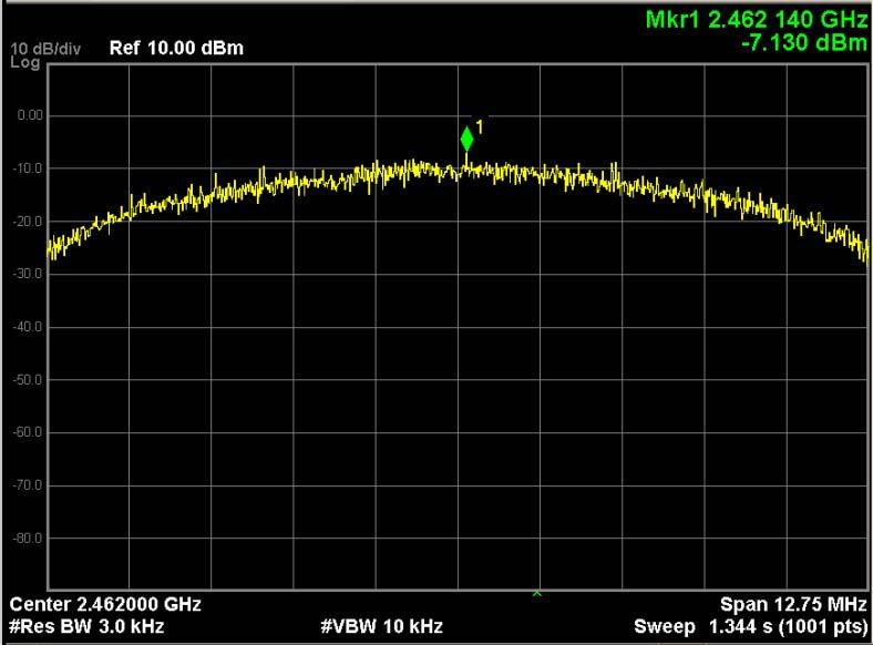
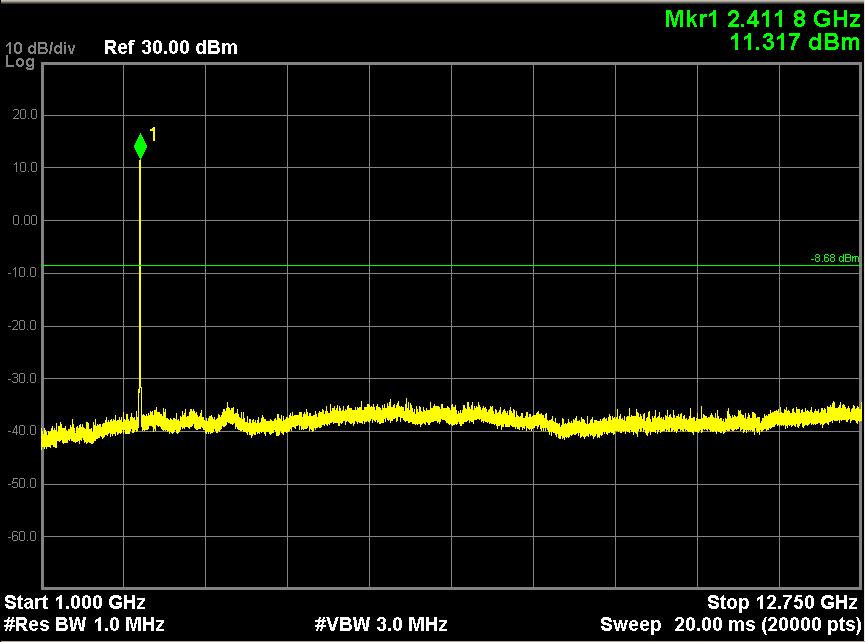
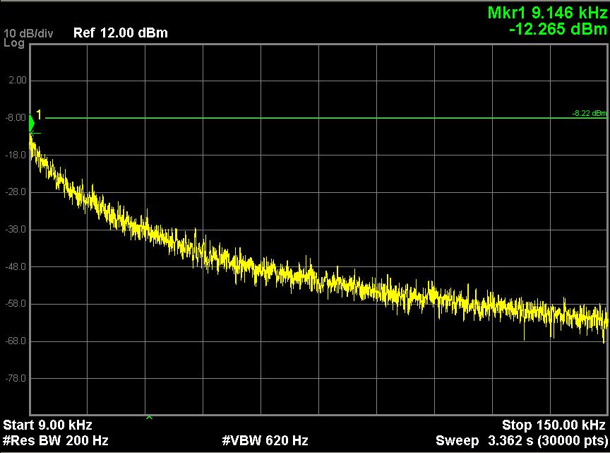
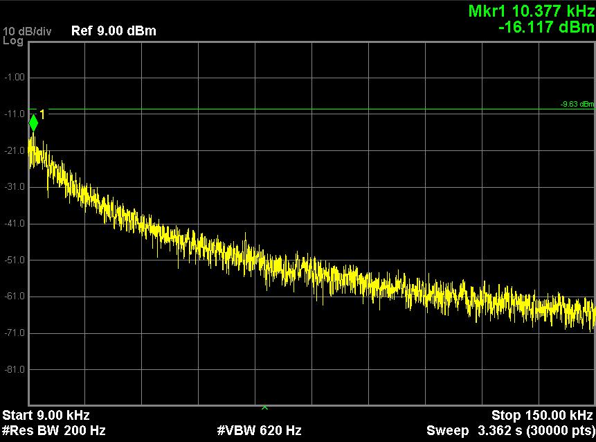
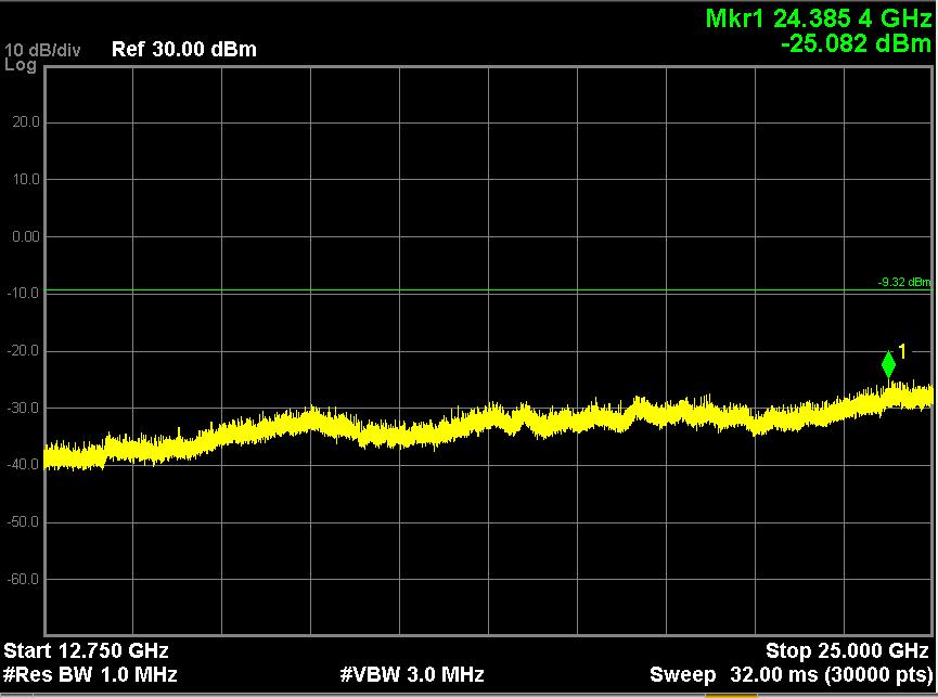
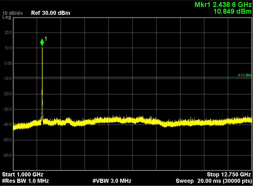
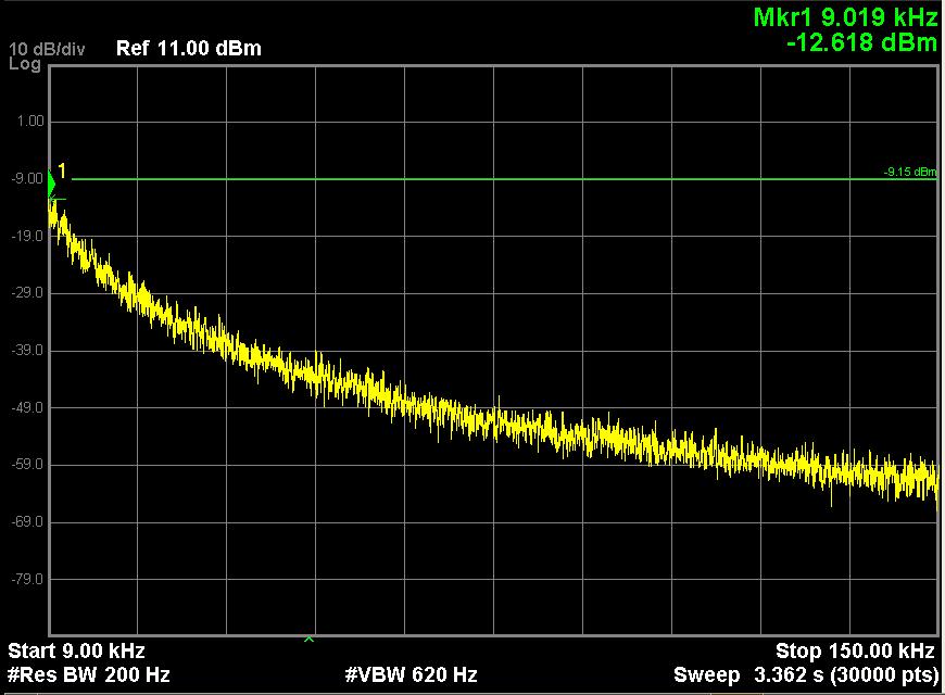
31 Report No. : UL CE/FCC002-5 Page 31 of SPURIOUS EMISSIONS (CONDUCTION) 8.1 TEST SETUP 8.2 LIMITS Limit Note: P is the highest level of the desired power <(P-20dB) 8.3 TEST PROCEDURE The EUT was connected to Spectrum Analyzer and Base Station via power divider. Use the following spectrum analyzer settings: Span = wide enough to capture the peak level of the in-band emission and all spurious emissions (e.g., harmonics) from the lowest frequency generated in the EUT up through the 10th harmonic. Typically, several plots are required to cover this entire span. RBW = 100 khz; VBW RBW; Sweep = auto; Detector function = peak; Trace = max hold Allow the trace to stabilize. Set the marker on the peak of any spurious emission recorded. The level displayed must comply with the limit specified in this Section.


32 Report No. : UL CE/FCC002-5 Page 32 of RESULTS & PERFORMANCE b, traffic mode; Channel 1

33 Report No. : UL CE/FCC002-5 Page 33 of 128 Note: The point mark1 is carrier.

34 Report No. : UL CE/FCC002-5 Page 34 of b, traffic mode; Channel 6

35 Report No. : UL CE/FCC002-5 Page 35 of 128

36 Report No. : UL CE/FCC002-5 Page 36 of 128 Note: The point mark1 is carrier.

37 Report No. : UL CE/FCC002-5 Page 37 of b, traffic mode; Channel 11

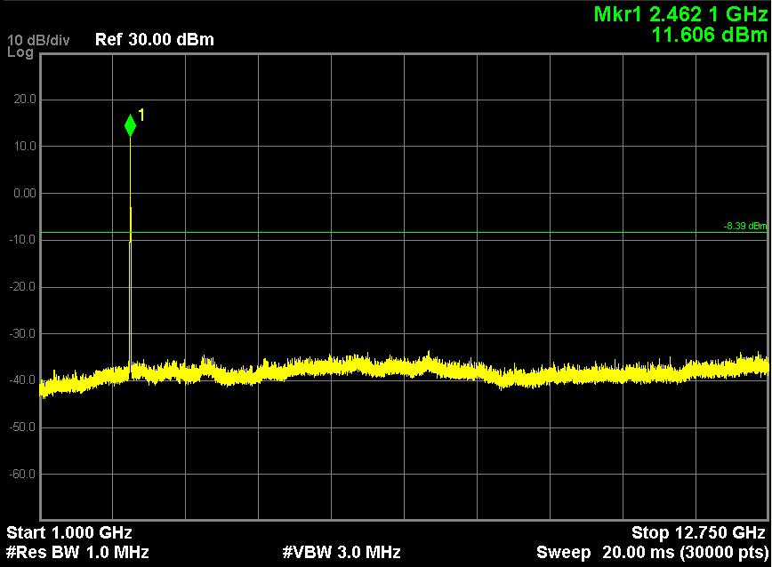
38 Report No. : UL CE/FCC002-5 Page 38 of 128 Note: The Mark1 point is carrier.

39 Report No. : UL CE/FCC002-5 Page 39 of 128
40 Report No. : UL CE/FCC002-5 Page 40 of g, traffic mode; Channel 1


41 Report No. : UL CE/FCC002-5 Page 41 of 128 Note: The Mark1 point is carrier.

42 Report No. : UL CE/FCC002-5 Page 42 of g, traffic mode; Channel 6
43 Report No. : UL CE/FCC002-5 Page 43 of 128

44 Report No. : UL CE/FCC002-5 Page 44 of 128 Note: The Mark1 point is carrier

45 Report No. : UL CE/FCC002-5 Page 45 of g, traffic mode; Channel 11

46 Report No. : UL CE/FCC002-5 Page 46 of 128 Note: The Mark1 point is carrier

47 Report No. : UL CE/FCC002-5 Page 47 of n20, traffic mode; Channel 1

48 Report No. : UL CE/FCC002-5 Page 48 of 128

49 Report No. : UL CE/FCC002-5 Page 49 of 128 Note: The Mark1 point is carrier.

50 Report No. : UL CE/FCC002-5 Page 50 of n20, traffic mode; Channel 6

51 Report No. : UL CE/FCC002-5 Page 51 of 128 Note: The Mark1 point is carrier.

52 Report No. : UL CE/FCC002-5 Page 52 of n20, traffic mode; Channel 11

53 Report No. : UL CE/FCC002-5 Page 53 of 128

54 Report No. : UL CE/FCC002-5 Page 54 of 128 Note: The Mark1 point is carrier.
55 Report No. : UL CE/FCC002-5 Page 55 of BAND EDGE MEASUREMENT 9.1 TEST SETUP Antenna tower EUT 3m 4m Horn antenna Spectrum analyzer Turntable 0.8m 1m Pre-amp 9.2 LIMITS According to (d), in any 100 khz bandwidth outside the frequency bands in which the spread spectrum intentional radiator in operating, the radio frequency power that is produced by the intentional radiator shall be at least 20dB below that in the 100kHz bandwidth within the band that contains the highest level of the desired power, In addition, radiated emissions which fall in the restricted bands, as defined in (a), must also comply with the radiated emission limits specified in15.209(a). 9.3 TEST PROCEDURE The EUT is placed on a turntable, which is 0.8m above the ground plane. The turntable shall be rotated for 360 degrees to determine the position of maximum emission level. EUT is set 3m away from the receiving antenna, which is varied from 1m to 4m to find out the highest emission. Set the spectrum analyzer in the following setting in order to capture the lower and upper band-edges of the emission: PEAK: RBW=VBW=1MHz / Sweep=AUTO AVERAGE: RBW=1MHz / VBW=10Hz / Sweep=AUTO Repeat the procedures until all the PEAK and AVERAGE versus POLARIZATION are measured.
56 Report No. : UL CE/FCC002-5 Page 56 of RESULTS & PERFORMANCE Radiated Band Edge: b (Ch1) Detector mode: Peak Polarity: Horizontal
57 Report No. : UL CE/FCC002-5 Page 57 of 128 Detector mode: Average Polarity: Horizontal
58 Report No. : UL CE/FCC002-5 Page 58 of 128 Detector mode: Peak Polarity: Vertical
59 Report No. : UL CE/FCC002-5 Page 59 of 128 Detector mode: Average Polarity: Vertical
60 Report No. : UL CE/FCC002-5 Page 60 of b (Ch11) Detector mode: Peak Polarity: Horizontal
61 Report No. : UL CE/FCC002-5 Page 61 of 128 Detector mode: Average Polarity: Horizontal
62 Report No. : UL CE/FCC002-5 Page 62 of 128 Detector mode: Peak Polarity: Vertical
63 Report No. : UL CE/FCC002-5 Page 63 of 128 Detector mode: Average Polarity: Vertical
64 Report No. : UL CE/FCC002-5 Page 64 of g (Ch1) Detector mode: Peak Polarity: Horizontal
65 Report No. : UL CE/FCC002-5 Page 65 of 128 Detector mode: Average Polarity: Horizontal
66 Report No. : UL CE/FCC002-5 Page 66 of 128 Detector mode: Peak Polarity: Vertical
67 Report No. : UL CE/FCC002-5 Page 67 of 128 Detector mode: Average Polarity: Vertical
68 Report No. : UL CE/FCC002-5 Page 68 of g (Ch11) Detector mode: Peak Polarity: Horizontal
69 Report No. : UL CE/FCC002-5 Page 69 of 128 Detector mode: Average Polarity: Horizontal
70 Report No. : UL CE/FCC002-5 Page 70 of 128 Detector mode: Peak Polarity: Vertical
71 Report No. : UL CE/FCC002-5 Page 71 of 128 Detector mode: Average Polarity: Vertical
72 Report No. : UL CE/FCC002-5 Page 72 of n20 (Ch1) Detector mode: Peak Polarity: Horizontal
73 Report No. : UL CE/FCC002-5 Page 73 of 128 Detector mode: Average Polarity: Horizontal
74 Report No. : UL CE/FCC002-5 Page 74 of 128 Detector mode: Peak Polarity: Vertical
75 Report No. : UL CE/FCC002-5 Page 75 of 128 Detector mode: Average Polarity: Vertical
76 Report No. : UL CE/FCC002-5 Page 76 of n20 (Ch11) Detector mode: Peak Polarity: Horizontal
77 Report No. : UL CE/FCC002-5 Page 77 of 128 Detector mode: Average Polarity: Horizontal
78 Report No. : UL CE/FCC002-5 Page 78 of 128 Detector mode: Peak Polarity: Vertical
79 Report No. : UL CE/FCC002-5 Page 79 of 128 Detector mode: Average Polarity: Vertical


80 Report No. : UL CE/FCC002-5 Page 80 of 128 Conducted Band Edge: b (Ch1) b (Ch11)
FCC Part 15B Measurement and Test Report
 FCC Part 15B Measurement and Test Report For mophie LLC 6224 Technology Ave. Kalamazoo, MI 49009 U.S.A. FCC ID: 2ACWB-SP6 Test Rule(s): Product Description: Tested Model: Report No.: FCC Part 15 Subpart
Clause Test Item Result. Section (b) (3) Maximum Average Conducted Output Power Pass. Section (e) Maximum Power Spectral Density Pass
 (3) Maximum Average Conducted Output Power Pass. Section (e) Maximum Power Spectral Density Pass") Test Result Summary Clause Test Item Result Section 15.247(b) (3) Maximum Average Conducted Output Power Pass Section 15.247(e) Maximum Power Spectral Density Pass Section 15.247(a) (2) 6 db Bandwidth
Test Result Summary Clause Test Item Result Section 15.247(b) (3) Maximum Average Conducted Output Power Pass Section 15.247(e) Maximum Power Spectral Density Pass Section 15.247(a) (2) 6 db Bandwidth
CE Test Report. : 45 Series WB module with Bluetooth
 CE Test Report Equipment Model No. Brand Name Applicant : 45 Series WB module with Bluetooth : WB45NBT : Laird Technologies : Laird Technologies Address : 11160 Thompson Ave. / Lenexa, Kansas / 66219 /
RADIO TEST REPORT FCC 47 CFR PART 15 SUBPART E INDUSTRY CANADA RSS-247
 FCC ID: PPQ-WCBN3507R12 ISED No.: 4491A-WCBN3507R12 Report No.: T171129W01-RP2 RADIO TEST REPORT FCC 47 CFR PART 15 SUBPART E INDUSTRY CANADA RSS-247 Test Standard FCC Part 15.407 and RSS-247 Issue 2 FCC
Test Report FCC ID: 2APBP-CS10. Date of issue: Apr. 10, 2018 CS10, CS10A, CS10B, CS10C, CS10D, CS10E, CS10F, CS11, CS12, CS13
 Test Report FCC ID: 2APBP-CS10 Date of issue: Apr. 10, 2018 Report Number: MTi180416E037 Sample Description: Smart POS Payment Terminal Model(s): CS10, CS10A, CS10B, CS10C, CS10D, CS10E, CS10F, CS11, CS12,
FCC DOC TEST REPORT. According to. 47 CFR, Part 2, Part 15, CISPR PUB. 22 ICES 003 Issue 6
 FCC DOC TEST REPORT According to 47 CFR, Part 2, Part 15, CISPR PUB. 22 ICES 003 Issue 6 Applicant Address Equipment Model No. Trade Name : Panasonic India Pvt. Ltd. : 6th Floor, "SPIC BUILDING" Annexe,
FCC Test Report. Report No.: FR750302AD Page : 1 of 46 Report Version: Rev. 01
 FCC Test Report FCC ID : ACQ-IP900 Equipment : Set Top Box Model No. : IP900 Brand Name : ARRIS Applicant : ARRIS Group, Inc. Address : 101 Tournament Drive, Horsham PA, 19044 Standard : 47 CFR FCC Part
ELEC-TECH INTERNATIONAL CO., LTD
 Test Report Number: LCZE17050061 Total Page(s): 21 Applicant Name: ELEC-TECH INTERNATIONAL CO., LTD Applicant Address: Test item: Model / Type Reference: No.1 Jinfeng Road, Tangjiawan Town, Xiangzhou District,
IC Test Report. : 3147A-SSD50NBT : abgn 2x2 and Bluetooth 4.0 module
 IC Test Report IC Equipment Model No. Brand Name Applicant : 3147A-SSD50NBT : 802.11abgn 2x2 and Bluetooth 4.0 module : SSD50NBT : Laird Technologies : Laird Technologies Address : 11160 Thompson Ave.,
FCC 15B Test Report. : Bluetooth v4.0 Dual-Mode UART HCI Module. Address : Thompson Ave., Lenexa, Kansas 66219, USA
 FCC 15B Test Report Equipment Model No. Brand Name Applicant : Bluetooth v4.0 Dual-Mode UART HCI Module : BT830-SA, BT830-ST (Please refer to item 1.1.1 for more details.) : Laird Technologies : Laird
HSDPA PCS High Channel -26dB BW. HSDPA PCS High Channel 99% BW
 HSDPA PCS High Channel -26dB BW HSDPA PCS High Channel 99% BW Page 51 of 152 LTE Band 2 (1880MHz)(1.4MHz BW) QPSK -26dB BW LTE Band 2 (1880MHz)(1.4MHz BW) QPSK 99% BW Page 52 of 152 LTE Band 2 (1880MHz)(1.4MHz
RF Test Report : FCC 47 CFR PART 22H FCC 47 CFR PART 24E ANSI/TIA-603-D Issue by
 RF Test Report Applicant Product Type Trade Name Model Number Test Specification : MANN HUMMEL FILTER TECHNOLOGY S.E.A. PTE. LTD. : Senzit : SENZIT : Senzit : FCC 47 CFR PART 22H FCC 47 CFR PART 24E ANSI/TIA-603-D
LONG-RANGE HANDHELD TRANSMITTER P/N: CMD-HHLR-xxx
 Page 1 of 16 FCC PART 15, SUBPART B and C TEST REPORT for LONG-RANGE HANDHELD TRANSMITTER Prepared for LINX TECHNOLOGIES 575 S.E. ASHLEY PLACE GRANTS PASS, OREGON 97526 Prepared by: KYLE FUJIMOTO Approved
FCC Test Report. : ac/a/b/g/n + Bluetooth 4.2 module (please refer to section for more details.)
") FCC Test Report FCC ID Equipment Model No. Brand Name Applicant Address : SQG-60SIPT : 802.11 ac/a/b/g/n + Bluetooth 4.2 module (please refer to section 1.1.1 for more details.) : ST60-SIPT (please refer
FCC Test Report FCC ID Equipment Model No. Brand Name Applicant Address : SQG-60SIPT : 802.11 ac/a/b/g/n + Bluetooth 4.2 module (please refer to section 1.1.1 for more details.) : ST60-SIPT (please refer
Report No. :EED32I Page 1of 70 1 COVER PAGE TEST REPORT. Product : HANDHELD VITALSIGNS MONITORING SYSTEM
 Report No. :EED32I00251304 Page 1of 70 1 COVER PAGE TEST REPORT Product : HANDHELD VITALSIGNS MONITORING Trade mark : SYSTEM Model/Type reference : BW-X07HD Serial Number : N/A Report Number : EED32I00251304
TEST REPORT. Intel Dual Band Wireless-AC 8265
 TESTING CERT #3478.01 TEST REPORT EUT Description Brand Name Model Name Serial Number FCC/IC ID Antenna type Hardware/Software Version Date of Sample Receipt Date of Test Features Applicant Address Contact
TEST REPORT. Fobsun Electronics Limited
 1 Cover Page Applicant: TEST REPORT Fobsun Electronics Limited Report No: GTSE12080097201 Address of Applicant: 4F, Building A6, Tianrui Industrial Park, Fuyuan 1st. Rd., Fuyong Town, Bao an Dist., 518103,
CE Radio Test Report
 CE Radio Test Report Report No. : EQ492517 CE Radio Test Report APPLICANT EQUIPMENT BRAND NAME MODEL NAME : FUJITSU LIMITED : Notebook : Fujitsu : U745 STANDARD : ETSI EN 300 440-1 V1.6.1 (2010-08) ETSI
Test of: Aruba Networks APIN0314, APIN0315. To: FCC CFR 47 Part 15 Subpart E Test Report Serial No.: ARUB204-U10_DFS Rev A
 TEST REPORT ADDENDUM DFS FROM Test of: Aruba Networks APIN0314, APIN0315 to To: FCC CFR 47 Part 15 Subpart E 15.407 Test Report Serial No.: ARUB204-U10_DFS Rev A Master Document Number ARUB204-U10_Master
EN 62311:2008 ASSESSMENT REPORT. Shanghai Bwave Technology Co.,Ltd.
 EN 62311:2008 ASSESSMENT REPORT For Shanghai Bwave Technology Co.,Ltd. 6F, Building 12, 399 Keyuan Road, Zhangjiang Hi-Tech Park, Shanghai, China Model: BW8800 Report Type: Amended Report Product Type:
MEASUREMENT/TECHNICAL REPORT. FCC Part 15 Sections Datalogic FCC ID: OMJ0006. June 23 rd, 2003
 MEASUREMENT/TECHNICAL REPORT FCC Part 15 Sections 15.207-15.209-15.249 Datalogic June 23 rd, 2003 This report concerns (check one): Original grant X Class II change Equipment type: RADIO MODEM (ex.: computer,
FCC Test Report. APPLICANT : ZTE CORPORATION EQUIPMENT : cdma2000 Digital Mobile Handset BRAND NAME : ZTE MODEL NAME : N8000
 FCC Test Report APPLICANT : ZTE CORPORATION EQUIPMENT : cdma2000 Digital Mobile Handset BRAND NAME : ZTE MODEL NAME : N8000 STANDARD : FCC 47 CFR FCC Part 15 Subpart B CLASSIFICATION : Certification The
ADDENDUM TO NMB TECHNOLOGIES INC. TEST REPORT FC FOR THE MICROSOFT WIRELESS ENTERTAINMENT KEYBOARD 7000, MICROSOFT MODEL NO.
 ADDENDUM TO NMB TECHNOLOGIES INC. TEST REPORT FC07-003 FOR THE MICROSOFT WIRELESS ENTERTAINMENT KEYBOARD 7000, MICROSOFT MODEL NO. 1073 FCC PART 15 SUBPART C SECTIONS 15.209, 15.247, AND RSS-210 ISSUE
12. Exhibit 12 FCC Test Report
 APPLICANT: Alcatel-Lucent USA Inc. -31 - FCC ID: AS5BBTRX-28 12. Exhibit 12 FCC Test Report FCC Test Report of Alcatel-Lucent AWS LTE B66a RRH 4x45 Outdoor Transceiver System Multi Carrier Operation under
TEST REPORT. For ELECTRONICS TECHNOLOGY (DONG GUAN) COMPANY LIMITED ETSI EN V1.4.1 ( ) ETSI EN V1.8.
 COMPANY LIMITED ETSI EN V1.4.1 ( ) ETSI EN V1.8.") TEST REPORT For ELECTRONICS TECHNOLOGY (DONG GUAN) COMPANY LIMITED No.161, Xin Min Road, Tong Luo Wei Industrial Zone, Jin Xia, Chang An Town, Dong Guan City, Guang Dong Province, China ETSI EN 301 489-3
TEST REPORT For ELECTRONICS TECHNOLOGY (DONG GUAN) COMPANY LIMITED No.161, Xin Min Road, Tong Luo Wei Industrial Zone, Jin Xia, Chang An Town, Dong Guan City, Guang Dong Province, China ETSI EN 301 489-3
FCC PART 15C TEST REPORT FOR CERTIFICATION On Behalf of. BYD Precision Manufacture Co., Ltd. Tablet PC FCC ID: ZW9-PDW0E
 FCC PAT 15C TEST EPOT FO CETIFICATION On Behalf of BYD Precision Manufacture Co., Ltd. Tablet PC Brand Name TOSHIBA Model No. WT7-C FCC ID: ZW9-PDW0E Prepared for : BYD Precision Manufacture Co., Ltd.
Test Report. Product Name: Wireless 11g CardBus Model No. : CB54G, MS-6819 FCC ID. : DoC. Date of Receipt : Jun. 12, 2003
 Test Report Product Name: Wireless 11g CardBus Model No. : CB54G, MS-6819 FCC ID. : DoC Applicant : MICRO-STAR INT L Co., LTD Address : No 69, Li-De st., Jung-He City, Taipei Hsien, Taiwan, R.O.C Date
EMI Test Report. Model Name: USB HUB Model Number: DX-B4PORT Brand Name: DYNEX Trade Mark: DYNEX FCC ID: XJIBLKDXB4PORT
 www.ecmg-global.com EMI Test Report Model Name: USB HUB Model Number: DX-B4PORT Brand Name: DYNEX Trade Mark: DYNEX FCC ID: XJIBLKDXB4PORT According to FCC Part 15, Class B Test Report #: Prepared by:
CE Test Report. : Bluetooth Serial Module with integrated antenna (Please refer to section for more details.)
") CE Test Report Equipment Model No. Brand Name Applicant : Bluetooth Serial Module with integrated antenna (Please refer to section 1.1.1 for more details.) : BTM431 (Please refer to section 1.1.1 for more
CE Test Report Equipment Model No. Brand Name Applicant : Bluetooth Serial Module with integrated antenna (Please refer to section 1.1.1 for more details.) : BTM431 (Please refer to section 1.1.1 for more
AS/NZS 4268 OUTPUT POWER & SPURIOUS EMISSIONS TEST REPORT For Intel Corporation Intel NUC Model Name: NUC7i3BNK Family Product Code: xnuc7xbnkx
 Page 1 of 35 AS/NZS 4268 OUTPUT POWER & SPURIOUS EMISSIONS TEST REPORT For Intel Corporation Intel NUC Model Name: NUC7i3BNK Family Product Code: xnuc7xbnkx (Where x may be a combination of alphanumeric
Test Report No. : F690501/RF-EMG Page : 2 of 9. Contents
 Page : 2 of 9 Contents 1. General Information...3 1.1 Client Information...3 1.2 Test Laboratory...3 1.3 General Information of E.U.T....3 1.4 Operating Modes and Conditions...3 1.5 Peripheral Equipments...3
Application for FCC Certificate On Behalf of Hisense Electric Co., Ltd. LED LCD TV
 Hisense Electric Co., Ltd. FCC ID: W9HLCDC0018 Page 1 of 26 Application for FCC Certificate On Behalf of Hisense Electric Co., Ltd. LED LCD TV Model No. LHD32K316MH Brand Hisense FCC ID : W9HLCDC0018 Prepared
TEST REPORT. Reference No... : WTS16S E FCC ID... : 2AC88-E1. Applicant... : HONGKONG UCLOUDLINK NETWORK TECHNOLOGY LIMITED
 TEST REPORT Reference No.... : WTS16S0243054-3E FCC ID... : 2AC88-E1 Applicant... : HONGKONG UCLOUDLINK NETWORK TECHNOLOGY LIMITED Address... : Unit D.16F.chenknang plaza 250 Hennessy Road,Wanchai Hongkong
TEST SUMMARY Seite 2 von 31. Prüfbericht - Nr.: Test Report No HARMONICS ON AC MAINS RESULT: Pass
 Prüfbericht - Nr.: Test Report No. Seite 2 von 31 Page 2 of 31 TEST SUMMARY 5.1.1 HARMONICS ON AC MAINS RESULT: Pass 5.1.2 VOLTAGE FLUCTUATIONS ON AC MAINS RESULT: Pass 5.1.3 DISTURBANCE VOLTAGE ON AC
Conducted Emissions, FCC Part 15
 Page 1 of 9 Temperature: 23 C Humidity: 31% Pressure: 830 mb Input Voltage: Configuration of Unit: Type Frequency (MHz) Test Engineer: Level (dbuv) 120Vac/60Hz Video playback mode Mike Tidquist Transducer
VCCI CLASS B COMPLIANCE REPORT
 VCCI CLASS B COMPLIANCE REPORT For Electromagnetic Emission Of Uninterruptible Power System Trade Name : APC Model Number : BK500JP Serial Number : N/A Report Number : HA020012-VI Issued Date : 12-APR-2002
REPORT NO: E6V2 DATE: JULY 24, F -13dBm F -13dBm
 CDMA ID: 44410 Date: 3/7/18 CDMA 1xRTT BC10 Limit Condition 816.35 823.65 F low @ F high @ Delta (Hz) Frequency Stability (ppm) Temperature Voltage (MHz) (MHz) Normal (20C) 816.5679 823.4405 Extreme (50C)
ONETECH Testing & Evaluation Lab.
 Page 1 of 13 ELECTROMAGNETIC EMISSION COMPLIANCE REPORT FOR FCC CLASS B CERTIFICATION Test report file number Applicant Address Manufacturer Address Type of Equipment FCC ID. Model / Type No. Serial number
FCC Test Report. : TomTom International BV : GPS Navigation System. : FCC 47 CFR FCC Part 15 Subpart B
 FCC Test Report APPLICANT EQUIPMENT BRAND NAME MODEL NAME FCC ID STANDARD CLASSIFICATION : TomTom International BV : GPS Navigation System : TomTom : 4CR51 : S4L4CR51 : FCC 47 CFR FCC Part 15 Subpart B
SK TECH CO., LTD. Page 2 of 52. Contents
 SK TECH CO., LTD. Page 2 of 52 Contents Contents 2 List of Supplements 3 List of Tables 3 List of Photographs 3 1. General 4 2. Test Site 4 2.1 Location 4 2.2 List of Test and Measurement Instruments 5
Honeywell, Automation and Control Solutions
 Honeywell, Automation and Control Solutions TH6320WF2003 FCC 15.207:2016 FCC 15.247:2016 802.11bgn SISO Radio Module Report # HNYW0156.3 NVLAP Lab Code: 200881-0 This report must not be used to claim product
TEST REPORT. EMC and Safety Laboratory No EMC13063 Page / Pages: 2 / 15 TABLE OF CONTENTS Description of the Equipment Under Test (EUT) 3
 3") No. 21583EMC13063 Page / Pages: 2 / 15 TABLE OF CONTENTS 1. Device under test / product description 3 1.1. Description of the Equipment Under Test (EUT) 3 1.2. Declared EUT configuration 4 2. Test results
No. 21583EMC13063 Page / Pages: 2 / 15 TABLE OF CONTENTS 1. Device under test / product description 3 1.1. Description of the Equipment Under Test (EUT) 3 1.2. Declared EUT configuration 4 2. Test results
RF EXPOSURE EVALUATION REPORT
 RF EXPOSURE EVALUATION REPORT APPLICANT PRODUCT NAME MODEL NAME BRAND NAME : S2E, Inc. : MEE audio connect hub : AF-CH : N/A FCC ID : 2ABMRC2HUB STANDARD(S) : 47CFR 2.1091 KDB 447498 D01 General RF Exposure
Declaration of Conformity (DoC)
") Declaration of Conformity (DoC) Per 47 CFR 2.1077(a) & 15.19(a)(3) The following device is herewith confirmed to comply with Part 15 of the FCC Rules. Product Name : Nuvo-3000 Series Main Model No. : Series
Declaration of Conformity (DoC) Per 47 CFR 2.1077(a) & 15.19(a)(3) The following device is herewith confirmed to comply with Part 15 of the FCC Rules. Product Name : Nuvo-3000 Series Main Model No. : Series
David Huang Checked By
 RF EXPOSURE REPORT Report No.: Supersede Report No.: N/A Applicant BLU Products, Inc. Product Name Mobile Phone Model No. STUDIO MEGA Serial No. N/A Test Standard FCC 2.1093:2016 Test Date March 30 to
FCC Test Report FCC ID:2AJJYPT7003
 FCC Test Report FCC ID:2AJJYPT7003 Product: Android Smart POS Trade Name: Anlinx Model Number: PT7003 Serial Model: PT7003S PT7003M PT7003MS Prepared for Shenzhen Anlinx Technology Company RM 1302, 13/F,
1601 North A.W. Grimes, Suite B Round Rock, TX (512) Fax: (512) January 20, 2012
 Fax: (512) January 20, 2012") 1601 North A.W. Grimes, Suite B Round Rock, TX 78665 e-mail: info@ptitest.com (512) 244-3371 Fax: (512) 244-1846 January 20, 2012 Mr. Bobby Wollard Dynamic Flow Computers 12603 Southwest Freeway Suite
1601 North A.W. Grimes, Suite B Round Rock, TX 78665 e-mail: info@ptitest.com (512) 244-3371 Fax: (512) 244-1846 January 20, 2012 Mr. Bobby Wollard Dynamic Flow Computers 12603 Southwest Freeway Suite
CE Test Report. : Class 1 Bluetooth Data Module : BT740-SA, BT740-SC, BT730-SA, BT730-SC (Refer to item for more details)
") CE Test Report Equipment Model No. Brand Name Applicant : Class 1 Bluetooth Data Module : BT740-SA, BT740-SC, BT730-SA, BT730-SC (Refer to item 1.1.1 for more details) : Laird : Laird Technologies Address
CE Test Report Equipment Model No. Brand Name Applicant : Class 1 Bluetooth Data Module : BT740-SA, BT740-SC, BT730-SA, BT730-SC (Refer to item 1.1.1 for more details) : Laird : Laird Technologies Address
Page 2 of 28 Ref. No: HZH-EMF1. Test item particulars...: Possible test case verdicts: - test case does not apply to the test object : N/A
 Page 2 of 28 Ref. No: 18349HZH-EMF1 Test item particulars...: Classification of installation and use.: Classification of installation and use.: Luminaire for normal use Appliance inlet and outlet Possible
EMC TEST REPORT (FULL COMPLIANCE)
") EMC TEST REPORT (FULL COMPLIANCE) Report Number: 102716227BOX-003 Project Number: G102716227 Report Issue Date: 03/22/2017 Model(s) Tested: µcor 3.0 Model(s) Partially Tested: None Model(s) Not Tested
EMC TEST REPORT (FULL COMPLIANCE) Report Number: 102716227BOX-003 Project Number: G102716227 Report Issue Date: 03/22/2017 Model(s) Tested: µcor 3.0 Model(s) Partially Tested: None Model(s) Not Tested
David Huang Checked By
 RF EXPOSURE REPORT Report No.: Supersede Report No.: N/A Applicant Telecell Mobile (H.K) Ltd. Product Name Mobile Phone Model No. ATRIUM II F55L2 Serial No. N/A Test Standard FCC 2.1093:2016 Test Date
Federal Communication Commission (FCC) Office of Engineering and Technology (OET) Program Accreditation Procedure
 Office of Engineering and Technology (OET) Program Accreditation Procedure") PJLA offers third-party accreditation services to Conformity Assessment Bodies (i.e. Testing and/or Calibration Laboratories, Reference Material Producers, Field Sampling and Measurement Organizations
PJLA offers third-party accreditation services to Conformity Assessment Bodies (i.e. Testing and/or Calibration Laboratories, Reference Material Producers, Field Sampling and Measurement Organizations
TEST REPORT NO.: BML FC
 BML TESTING LABORATORY (NO. 1) for Electro-Magnetic Compatibility BENQ DENMARK APS TEST REPORT NO.: BML FC 002.2006 Test specification: Sub standard: Ordered by: Address: Subject: Verification: CFR47 part
SCOPE OF ACCREDITATION TO ISO/IEC 17025:2005
 SCOPE OF ACCREDITATION TO ISO/IEC 17025:2005 SHENZHEN MORLAB COMMUNICATIONS TECHNOLOGY CO. LTD. Fl. 3, Building A, Fei Yang Science Park No. 8 Long Chang Road, Block 67 BaoAn District, Guangdong Province,
Application for FCC Certificate On Behalf of Hisense Electric Co., Ltd. LED LCD TV
 Hisense Electric Co., Ltd. FCC ID: W9HLCDF0082 Page 1 of 30 Application for FCC Certificate On Behalf of Hisense Electric Co., Ltd. LED LCD TV Model No. PLDED6079-SM Brand Proscan FCC ID : W9HLCDF0082
Application for FCC Certificate On Behalf of Hisense Electric Co., Ltd. LED LCD TV. Model No.
 Hisense Electric Co., Ltd. FCC ID: W9HLCDF0109 Page 1 of 64 Application for FCC Certificate On Behalf of Hisense Electric Co., Ltd. LED LCD TV Model No.: Model No. 55H8D,55H8D+,55H8+0D,55H8+0D1, 55H80+0D,55H80+0D1,55H8C,55H8C+,
Application for FCC Certificate On Behalf of Hisense Electric Co., Ltd. LED LCD TV
 Hisense Electric Co., Ltd. FCC ID: W9HLCDF0073 Page 1 of 31 Application for FCC Certificate On Behalf of Hisense Electric Co., Ltd. LED LCD TV Model No. LC-60N5100U, LC-60N5100C Brand Sharp FCC ID : W9HLCDF0073
Application for FCC Certificate On Behalf of Hisense Electric Co., Ltd. LED LCD TV LC-43N7000U, LC-43N7000C
 Hisense Electric Co., Ltd. FCC ID: W9HLCDD0061 Page 1 of 36 Application for FCC Certificate On Behalf of Hisense Electric Co., Ltd. LED LCD TV Model No LC-43N7000U, LC-43N7000C Brand Sharp FCC ID : W9HLCDD0061
FCC TEST REPORT. for. 47 CFR FCC Rules and Regulations Part 15 Subpart B, Class A Digital Device
 Report No. : FV083127 FCC TEST REPORT for 47 CFR FCC Rules and Regulations Part 15 Subpart B, Class A Digital Device Equipment Model No. FCC ID Filing Type Applicant : Fan Free Touch Terminal : XP-3315H,
Application for FCC Certificate On Behalf of Hisense Electric Co., Ltd. LED LCD TV
 Hisense Electric Co., Ltd. FCC ID: W9HLCDD0054 Page 1 of 36 Application for FCC Certificate On Behalf of Hisense Electric Co., Ltd. LED LCD TV Model No. LC-43N6100U, LC-43N6100C Brand Sharp FCC ID : W9HLCDD0054
(Where x may be a combination of alphanumeric characters or blank) Brand: Intel
 Brand: Intel") Page 1 of 22 ETSI EN 300 440-1 & ETSI EN 300 440-2 5.8GHz OUTPUT POWER & SPURIOUS EMISSIONS TEST REPORT For Intel Corporation Intel NUC Model Name: NUC7i3BNH Family Product Code: xnuc7xbnhx (Where x may
Page 1 of 22 ETSI EN 300 440-1 & ETSI EN 300 440-2 5.8GHz OUTPUT POWER & SPURIOUS EMISSIONS TEST REPORT For Intel Corporation Intel NUC Model Name: NUC7i3BNH Family Product Code: xnuc7xbnhx (Where x may
Intel Corporation. DuPont Site EMC Laboratory. Ferrite Clamp/Tube Analysis CISPR/G/143/CDV. 31 August 1999
 Intel Corporation DuPont Site EMC Laboratory Ferrite Clamp/Tube Analysis CISPR/G/143/CDV 31 August 1999 Ghery S. Pettit, NCE Intel Corporation 2800 Center Drive DuPont, Washington 98327 (253) 371-5515
IEEE Testing Signal Compliance of ZigBee Standard
 IEEE802.15.4 Testing Signal Compliance of ZigBee Standard Tektronix 1 Agenda: 1: What is ZigBee 2: ZigBee Specification 3: ZigBee Signal Analysis 4: Demonstration for ZigBee analysis 2 What is ZigBee (1)
COMMON REGULATORY OBJECTIVES FOR GSM EQUIPMENT PART 2 SPECIFIC ASPECTS OF GSM EQUIPMENT
 COMMON REGULATORY OBJECTIVES FOR GSM EQUIPMENT PART 2 SPECIFIC ASPECTS OF GSM EQUIPMENT 1. SCOPE This Common Regulatory Objective, CRO, is applicable to GSM equipment, as defined in Clause 2. A CRO is
Variant FCC SAR Exclusion Report
 Variant FCC SAR Exclusion Report Report No. Applicant Address Product Brand FCC ID Model No. : SA170301C11C : HTC Corporation : No.23 Xinghua Road,Taoyuan District, Taoyuan City 330, Taiwan : Smartphone
SCOPE OF ACCREDITATION TO ISO/IEC 17025:2005
 SCOPE OF ACCREDITATION TO ISO/IEC 17025:2005 TA TECHNOLOGY (SHANGHAI) CO., LTD. Building 3, No. 145 Jintang Rd. Tangzhen Industry Park Pudong, Shanghai, People s Republic of China Mr. Zhihui (Henry) Liu
R&S ESW Test Receiver Release Notes Firmware Version V1.40 SP1
 R&S ESW Test Receiver Release Notes Firmware Version V1.40 SP1 These Release Notes are for following models of the R&S ESW EMI Test Receiver: R&S ESW8, order no. 1328.4100.08 R&S ESW26, order no. 1328.4100.26
Federal Communications Commission Office of Engineering and Technology Laboratory Division
 Federal Communications Commission Office of Engineering and Technology Laboratory Division Guidelines for Labelling and User Information for Devices Subject to Part 15 and Part 18 1. General This document
Read Me First for the HP ProCurve Wireless Products - software ver
 Read Me First for the Wireless Products - software ver. 2.1.0 This Read Me First provides information for the following products: Wireless Access Point 520wl (J8133A) 802.11a AP Kit 160wl - N America +
SCOPE OF ACCREDITATION TO ISO/IEC 17025:2005
 SCOPE OF ACCREDITATION TO ISO/IEC 17025:2005 MICROSOFT EMC LABORATORY 1 17760 NE 67 th Court Redmond, WA 98052 Sajay Jose Email: sajose@microsoft.com Phone: 425 421 9799 ELECTRICAL (EMC) Valid to: August
REPORT OF ELECTROMAGNETIC SUSCEPTIBILITY TESTS PERFORMED ON GPS ANTENNA PART NUMBER 42G1215A-XT-1-N PREPARED FOR:
 Page 1 of 64 National 1536 East Valencia Drive Technical Fullerton, California 92831 Systems Tel: 714-879-6110 Fax: 714-879-6117 www.ntscorp.com REPORT OF ELECTROMAGNETIC SUSCEPTIBILITY TESTS PERFORMED
Manual Supplement. This supplement contains information necessary to ensure the accuracy of the above manual.
 Manual Title: Supplement Issue: 8 Part Number: 1625019 Issue Date: 9/17 Print Date: October 2011 Page Count: 12 Revision/Date: 11 This supplement contains information necessary to ensure the accuracy of
SpectrumShot. Software for the GSP-9330 Spectrum Analyzer QUICK START GUIDE REVISION MAY 2016 ISO-9001 CERTIFIED MANUFACTURER
 SpectrumShot Software for the GSP-9330 Spectrum Analyzer QUICK START GUIDE REVISION 2.0.0.1 MAY 2016 ISO-9001 CERTIFIED MANUFACTURER This manual contains proprietary information, which is protected by
THE ISM BAND A REVIEW OF THE ESSENTIALS
 HISTORY: In 1985 the Federal Communications Commission issued rules permitting intentional radiators to use the Industrial, Scientific and Medical (ISM) Bands ( 902-928, 2400-2483.5, 5725-5850 Mhz) at
SPORTON INTERTIONAL INC. EMC & Wireless Communications Laboratory No. 52, Huaya 1st Rd., Guishan Dist., Taoyuan City, Taiwan (R.O.C.
 RF EXPOSURE EVALUATION REPORT FCC ID Equipment : UDX-60076017 : LTE Router Brand Name : CISCO Model Name : MX67C-HW-NA Applicant : Cisco Systems, Inc. 170 West Tasman Drive, San Jose, CA 95134 Standard
2x2 IEEE a/n High Power Mini PCI Radio Module
 nm2-4940 2x2 IEEE 802.11 a/n High Power Mini PCI Radio Module nm2-4940 is an IEEE 802.11 a/n 4940 MHz to 4990 MHz Radio Module built over Vizmonet s innovative Built-to-Customize TM platform engineered
CONTENTS 1. PRODUCT GENERAL INFORMATION Product Description Product Feature Product Application...2
 CONTENTS 1. PRODUCT GENERAL INFORMATION.....2 1.1. Product Description.2 1.2. Product Feature... 2 1.3. Product Application...2 2. PRODUCT GENERAL..3 2.1. General Specifications..... 3 2.2. LED Indicator.....
REPORT OF ELECTROMAGNETIC SUSCEPTIBILITY TESTS PERFORMED ON GPS ANTENNA PART NUMBER 42G1215A-XT-1-N PREPARED FOR:
 Page 1 of 40 National 1536 East Valencia Drive Technical Fullerton, California 92831 Systems Tel: 714-879-6110 Fax: 714-879-6117 www.ntscorp.com REPORT OF ELECTROMAGNETIC SUSCEPTIBILITY TESTS PERFORMED
Specification For 90 Watts Adapter Power Supply Model No: ADB002 Customer ID: 000G Revision: 4.0
 Specification For 90 Watts Adapter Power Supply Model No: ADB002 Customer ID: 000G Revision: 4.0 Prepared By: Terry Liou Approved By: Jacky Chi PAGE 1 E. C. List 1.0 Original 2.0 Modify 8.3 Weight 3.0
SCOPE OF ACCREDITATION TO ISO/IEC 17025:2005
 SCOPE OF ACCREDITATION TO ISO/IEC 17025:2005 A TEST LAB TECHNO CORP. 101-104, 1F, A Building, Taoyuan Street Safflower Ridge Industrial Area, Nanshan District Shenzhen, 518055, People s Republic of China
CPRI RF Analyzer and BBU Emulator
 Measurement Guide CPRI RF Analyzer and BBU Emulator for Anritsu RF and Microwave Handheld Instruments CPRI Common Public Radio Interface BBU Base Band Unit Anritsu Company 490 Jarvis Drive Morgan Hill,
EMC TEST REPORT (Class B)
") Page 1 of 32 EMC TEST REPORT (Class B) REGULATORY MODEL NUMBER: 25413 REGULATORY TYPE: N/A REPORT NUMBER: TA11008T ISSUED DATE: June 20, 2011 Applicant: LSI Corporation 3718 N. Rock Road Wichita, KS 67226
Page 1 of 32 EMC TEST REPORT (Class B) REGULATORY MODEL NUMBER: 25413 REGULATORY TYPE: N/A REPORT NUMBER: TA11008T ISSUED DATE: June 20, 2011 Applicant: LSI Corporation 3718 N. Rock Road Wichita, KS 67226
FCC RF Exposure Report
 FCC RF Exposure Report FCC ID Equipment Model No. Brand Name Applicant : SQGBT900US : Intelligent BT4.0 Dual Mode USB Dongle : BT900-US : Laird Technologies : Laird Technologies Address : 11160 Thompson
MMC543AHVN2-26. Wireless Indoor Access Point. Atheros XR extended Range technology. MIPS 24K-family 680MHz network processor
 product datasheet MMC543AHVN2-26 Wireless Indoor Access Point Features Atheros XR extended Range technology MIPS 24K-family 680MHz network processor IEEE 802.11n compliant and backward compatible with
SCOPE OF ACCREDITATION TO ISO/IEC 17025:2005
 SCOPE OF ACCREDITATION TO ISO/IEC 17025:2005 GLOBAL COMPLIANCE AND TESTING CENTER OF HUAWEI TECHNOLOGIES CO., LTD. (RELIABILITY LABORATORY OF HUAWEI TECHNOLOGIES CO., LTD.). 1 Administration Building,
HIGH SPEED SIGNAL CHAIN SELECTION GUIDE
 HIGH SPEED SIGNAL CHAIN SELECTION GUIDE Includes High Speed Cs, DACs, Amplifiers, and Clocking Solutions Visit analog.com and linear.com High Speed Signal Chain Product Selection Guide TABLE OF CONTENTS
SURE TO HAVE YOUR PROOF OF PURCHASE. RETURN REQUESTS CAN NOT BE PROCESSED WITHOUT PROOF OF PURCHASE.
 LIMITED WARRANTY Hawking Technology guarantees that every HSB2 WiFi Signal Booster is free from physical defects in material and workmanship under normal use for two (2) years from the date of purchase.
Insights into EMC Chamber Design:
 Insights into EMC Chamber Design: How to achieve an optimized chamber for accurate EMC Measurements Zubiao Xiong, PhD zubiao.xiong@ets-lindgren.com November 16, 2017 EMC Compliance Testing Emission (Disturbance)
Data Sheet. ProLock. 3G test set for service. Boosting wireless efficiency
 Data Sheet 2201 ProLock 3G test set for service Boosting wireless efficiency Willtek 2201 ProLock Service Testing for 2G and 3G Mobile Communications Service centres for mobile phones perform repair on
Sampe Approval Drawing
 深 Sampe Approval Drawing Please feel free to contact us in the following ways, we must reply you within 24 hours! Sales Email: market@smodule.com Support Email: support@smodule.com Contents 1.General Description...
Data Sheet. ProLock. 3G test set for service. Boosting wireless efficiency
 Data Sheet 2201 ProLock 3G test set for service Boosting wireless efficiency Willtek 2201 ProLock Service Testing for 2G and 3G Mobile Communications Service centres for mobile phones perform repair on
Manual Supplement. This supplement contains information necessary to ensure the accuracy of the above manual.
 Manual Supplement Manual Title: 601PRO XL Operators Supplement Issue: 5 Part Number: 2234222 Issue Date: 9/18 Print Date: April 2005 Page Count: 5 Revision/Date: This supplement contains information necessary
EMC TEST REPORT (Class B)
") Page 1 of 32 EMC TEST REPORT (Class B) REGULATORY MODEL NUMBER: 25528 REGULATORY TYPE: N/A REPORT NUMBER: TA13033V ISSUED DATE: October 24, 2013 Applicant: LSI Corporation 3718 N. Rock Road Wichita, KS
Page 1 of 32 EMC TEST REPORT (Class B) REGULATORY MODEL NUMBER: 25528 REGULATORY TYPE: N/A REPORT NUMBER: TA13033V ISSUED DATE: October 24, 2013 Applicant: LSI Corporation 3718 N. Rock Road Wichita, KS
PRELIMINARY DRAFT FOR CONSULTATION
 PRELIMINARY DRAFT FOR CONSULTATION.. STATUTORY INSTRUMENTS 2012 No. ELECTRONIC COMMUNICATIONS The Wireless Telegraphy (White Space Devices) (Exemption) Regulations [ ] Made - - - - *** Coming in force
200M Powerline Wireless N Extender
 200M Powerline Wireless Extender High Speed Wireless Extension via Home s Powerline With HomePlug AV technology, the PLAET Powerline Wireless Extender efficiently share up to 200/300Mbps high speed In-house
SSA3000X Series Spectrum Analyzer. Quick Guide
 SSA3000X Series Spectrum Analyzer Quick Guide Copyright Information SIGLENT TECHNOLOGIES CO., LTD. All Rights Reserved. Information in this publication replaces all previously corresponding material. SIGLENT
TO65SS 65 SINGLE SIDED TOTEM VERTICAL DIGITAL SIGNAGE DISPLAY
 PRODUCT SPECIFICATION Date:08.01.2017 TO65SS 65 SINGLE SIDED TOTEM VERTICAL DIGITAL SIGNAGE DISPLAY 1 SPECIFICATIONS TO65SS Panel H-Freq 67.5 khz Max. Pixel Freq. 74.25 MHz V-Freq 60 Hz Cabinet T05 Backlight
The challenges, opportunities and setting the framework for 5G EMF and Health
 The challenges, opportunities and setting the framework for 5G EMF and Health 5G, EMF & Health 5 December 2017, Warsaw, Poland Mike Wood - General Manager Telstra EME Strategy, Governance and Risk Management
SCOPE OF ACCREDITATION TO ISO/IEC 17025:2005
 SCOPE OF ACCREDITATION TO ISO/IEC 17025:2005 SHENZHEN ACADEMY OF METROLOGY AND QUALITY INSPECTION 1 NETC Building, No. 4 Tongfa Road Xili, Nanshan Shenzhen, Guangdong, 518055, People s Republic of China
Emerging communication technologies enabling the Internet of Things IoT system design challenges and testing solutions
 Emerging communication technologies enabling the Internet of Things IoT system design challenges and testing solutions Feng XIE 谢丰 Market Segment Manager Smart Testing for a smart world COMPANY RESTRICTED