Cygnos360 V2 Installation Manual
|
|
|
- Jocelyn Bell
- 6 years ago
- Views:
Transcription

1 Cygnos360 V2 Installation Manual VERSION MARCH,
2 Contents: Cygnos360 V2 Installation Manual What you need Tools Preparation Preparing the solder points Installing in your Xbox Installing the main PCB Installing the USB board Software installation Cygnos Toolbox Building the jtag hack image Preparing the necessary tools Build your image Troubleshooting Cygnos360 V2 Installation Manual ii
3
4 1. What you need 1.1. Tools Cygnos360 V2 has been designed to require as little as possible skills to install and use. However, to ensure a good and clean installation some tools may come very handy to you. We assume you know how to open your Xbox360. If not, there are good tutorials on the net. What you need is: 1) a Cygnos360 V2 2) 4 x 330 Ohm resistors (THESE ARE NOT NECESSARY ANYMORE IF YOU USE firmware v1.03 beta 2) 3) An Xbox360 with 16Mb NAND (please note that the 256 and 512 Mb Jasper mainboards are not supported yet) 4) A soldering iron (it should have a fine top, as the quicksolder pads are very small) 5) Some good solder 6) some thin wires (kynar would be preferred) 7) 4 M3 screws with nuts 8) A PC with Windows (XP or Vista) 9) The Cygnos360 V2 Toolbox (Please check our Forum news section for updates ) 10) Some patience Cygnos360 V2 Installation Manual 2

5 2. Preparation In order to make sure that the installation of your Cygnos360 is smooth and you do not have to troubleshoot later on, you should make some preparations before you install it Preparing the solder points Cygnos360 V2 is soldered directly onto the bottom side of the Xbox360 mainboard. Microsoft uses lead-free solder for manufacturing. This causes some trouble when trying to solder anything onto the mainboard. We therefore highly recommend that you mix some good solder (try to get some SMD solder) onto all the points where you will solder Cygnos360 V2 onto. This ensures that you do not end up with cold solder joints and a non-working Cygnos360 V2. Cygnos360 V2 Installation Manual 3
6 Alternatively to the RB solder point on the Cygnos360 V2 and using a wire, you can use the RB point at the quicksolder pad of Cygnos360 V2. The blue marked spot is where you need to carefully scratch off the green paint to get to the copper. You can then solder some tin onto that and then use it as a quicksolder point as well. (which means you need one less wire. 4 Cygnos360 V2 Installation Manual

7 3. Installing in your Xbox Installing the main PCB Cygnos360 V2 is installed directly onto the bottom side of the Xbox360 mainboard underneath the flash memory (NAND). Please make sure you have done the preparation as stated above. Put the flat cable into Cygnos360 V2 before you install it! It is easier than if you try that later. Place the PCB directly onto the bottom solder points of the Xbox360 onboard NAND flash and make sure it is even on the surface of the mainboard. Use the quick-solder pads to align Cygnos360 V2 and fix it with some duct tape to the mainboard to avoid it from moving around. As the next step solder the quick-solder pads. If you have prepared them before with some good solder this should not take more than 3 minutes. As the next step, solder the GND wire ground, for example directly to the copper on the side. Then also solder the RB cable. Top Side of mainboard (thanks 80Y for the pic) As an alternative to the RB cable you can scratch off the RB point on the mainboard as described in the chapter 2.1 Cygnos360 V2 Installation Manual 5
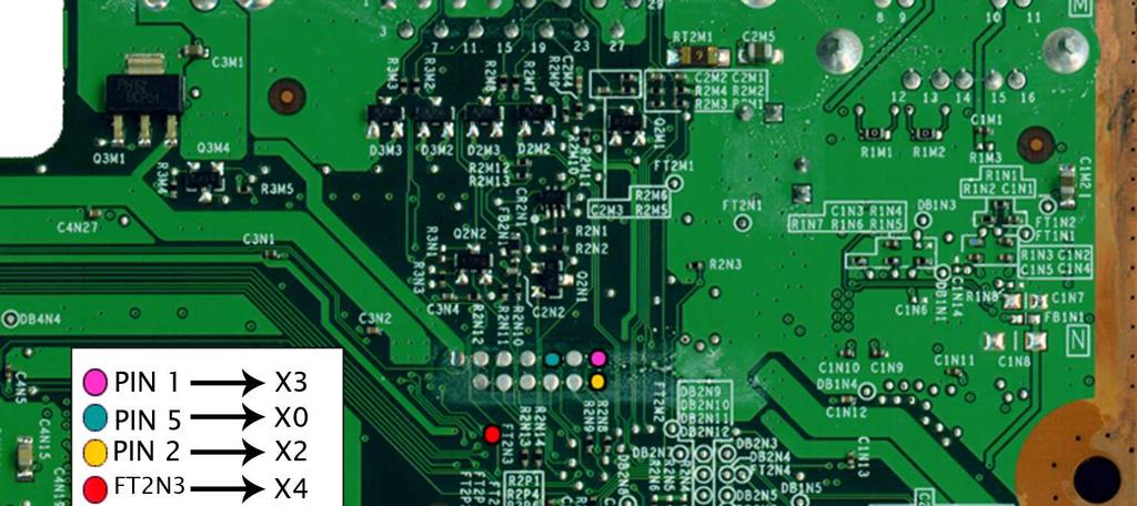
8 TABLE FOR CYGNOS360 V2 REVISIONS C,D & E Cygnos360 V2 Solder Point Xbox360 solder point Comments VCC GND RB C2R6 Good GND, preferable copper Above the line at R1P7 X0 J2B1 PIN 5 X1 J2D2 PIN 1 Via 330 ohm! X2 J2B1 PIN 2 X3 J2B1 PIN 1 IF YOU ARE BELOW CYGNOS FIRMWARE 1.03 Beta 2 X4 FT2N3 X5 J2D2 PIN 2 Via 330 ohm! X6 J2D2 PIN 4 Via 330 ohm! X7 J2D2 PIN 5 Via 330 ohm! IF YOU ARE BELOW CYGNOS FIRMWARE 1.03 Beta 2 IF YOU ARE BELOW CYGNOS FIRMWARE 1.03 Beta 2 IF YOU ARE BELOW CYGNOS FIRMWARE 1.03 Beta 2 6 Cygnos360 V2 Installation Manual


9 Bottom Side of mainboard WHEN USING FIRMARE 1.03 Beta 2 OR HIGHER THE RESISTORS ARE NOT NEEDED ANYMORE. LEAVE OUT RESISTORS ONLY IF YOU ARE ON 1.03 Beta2 OR HIGHER!!! OTHERWISE YOU CAN DAMAGE YOUR 360!!! Cygnos360 V2 Installation Manual 7


10 8 Cygnos360 V2 Installation Manual
11 TABLE FOR REVISION F (for 256Mb & 512Mb Jaspers) Cygnos360 V2 Solder Point Xbox360 solder point Comments VCC GND RB C2R6 Good GND, preferable copper Above the line at R1P7 SR J2B1 PIN 5 RX J2B1 PIN 2 TX J2B1 PIN 1 PW FT2N3 Cygnos360 V2 Installation Manual 9
12 After soldering the Cygnos360 V2 main PCB, we recommend that you put some tape on top of the places where you soldered cables. This is to avoid that you short circuit anything with the metal cage. Put the mainboard back in the cage, attach the USB board and move to section 4 Software installation before continuing with the installation. When closing the box, also use some duct tape to protect the flat cable from cuts of the metal cage to avoid any damage. Leave out the screw in the corner to not put too much pressure on the cable. 10 Cygnos360 V2 Installation Manual

13 Cygnos360 V2 Installation Manual 11


14 3.2. Installing the USB board You are free to install the USB board where you want but we recommend the following installation: A good place to put the USB board is in front of the HDD slot. The place is easy to reach and not hard to cut a hole into and the blue LED of the Cygnos360 V2 USB board shines through nicely. Make sure you cut the hole exactly as in the pictures here, otherwise you might hit some plastic parts on the front which will hinder you from closing the part while the Cygnos V2 USB board is installed. Before fixing the USB board here with the M3 screws, attach the flat cable to it. Make sure you don t do it upside down! Plug the power into your Xbox360 and check if the blue LED shines when you switch to ON. Take out the power plug again to avoid any shorting on the metal cage. Now screw the M3 screws directly into the grid. Place the USB board onto the screws and attach the nuts from below. Now you can put the part back on the Xbox360 and you are done! 12 Cygnos360 V2 Installation Manual


15 4. Software installation Plug in the power of your Xbox360. Don t turn on the Xbox360. Switch Cygnos360 V2 to ON so you can verify if the LED is lit. If you switch Cygnos360 V2 to ON and then plug the power of the Xbox360 in, Cygnos360 V2 will go into bootloader mode and the LED will be blinking. If everything is fine, connect Cygnos360 V2 with the USB port of your PC. You should see the following prompts. Select install from a specific location and point to the directory where you put the Cygnos360 V2 drivers. Cygnos360 V2 Installation Manual 13

16 Now that you have successfully installed Cygnos360 V2 drivers on your PC, you can proceed and launch the Cygnos360 V2 Toolbox. 14 Cygnos360 V2 Installation Manual
17 5. Cygnos Toolbox When you start the Cygnos Toolbox you will see that all the controls are marked out grey. PLEASE CHECK THE NEWS SECTION IN THE FORUM FOR THE LATEST TOOLBOX VERSION ( ) As soon as you plug in your USB cable and connect it to Cygnos360 V2 the toolbox will recognize it and show the status connected as well as the currently selected NAND flash. (either Cygnos NAND or Xbox360 NAND). If you flip the switch you can see that the selection of the flash memory changes. When the LED is lit in blue the toolbox should show Cygnos NAND if it is not lit it should be Xbox360 NAND. Cygnos360 V2 Installation Manual 15

18 Now that you have established the connection between the toolbox and Cygnos360 V2 you can start to read flash, program the flash or program Cygnos360 V2 with a new firmware. Reading the NAND-Flash: To read out the flash and dump it to your hard disk, simply go to the read tab. Select Browse to define the location and the name for the dump file. Make sure you have selected the correct flash that you want to read out. Either the Cygnos360 V2 s own NAND or the one on the Xbox360 mainboard. After selecting location and filename press Read. You will see a progress bar to indicate how far you are in the dump. If anything goes wrong here, please refer to the troubleshoot section below. 16 Cygnos360 V2 Installation Manual
19 In this screenshot you are reading the flash of the onboard NAND-flash Cygnos360 V2 Installation Manual 17
 Klick on browse to select the image file that you want to flash to the NAND.")
20 Programming the NAND-Flash: Ok, you are going to program something to your Xbox360 NAND or the Cygnos360 V2 NAND now. PLEASE make sure that you have a dump of the original before you proceed. It will save you a lot of time ;-) Klick on browse to select the image file that you want to flash to the NAND. Make sure you have the correct one selected (either Cygnos360 V2 NAND or Xbox360 NAND) before you proceed. After selecting the file click on program and the toolbox will erase the flash and then program the image you have selected. The progress bar will indicate how long it will take. If anything goes wrong here, please refer to the troubleshoot section below. In this screenshot you are programming the flash of the onboard NAND-flash 18 Cygnos360 V2 Installation Manual
21 Programming the firmware: This process will erase the firmware of the microcontroller on the Cygnos360 V2 and replace it with a different version. Please make sure that you ONLY use firmwares that you have directly downloaded from our website. Click the Firmware tab and select browse. Now choose the firmware image you want to flash to the Cygnos360 V2. It does not matter if you have your switch set to Cygnos360 or Xbox360. Click on Program to start the firmware update. This will go very fast, so don t wonder why you don t see much. (in this screenshot you are programming firmware on the Cygnos360 V2 microcontroller) Cygnos360 V2 Installation Manual 19
22 6. Building the jtag hack image 6.1. Preparing the necessary tools 1) Getting XeLL Since our microcontroller cannot handle serial communication at baud, we had to make a minor modification to XeLL. The modification will set the baud rate register of the Xbox 360 to baud, 8 data bits, no parity and one stop bit. This implies that you have to build a custom JTAG hack image for Cygnos360 V2 with our modified XeLL. You can download the XeLL binaries and sources from here: XeLL Binaries for Cygnos360 V2.zip Get it here: ( XeLL Sources for Cygnos360 V2.zip Get it here: ( 2) Getting imgbuild The free60 imgbuild tool does by default not generate a full image as required by our toolbox. We therefore modified the build script accordingly. You can download the whole package from here: imgbuild for Cygnos360 V2.zip (updated ) Get it here: ( 3) Get and install Cygwin Building your own image under Windows requires the installation of a Python interpreter. The simplest way is to download and install the Cygwin base system along with the "python" and "python-crypto" packages from here: 20 Cygnos360 V2 Installation Manual
23 6.2. Build your image Our modified imgbuild tool does not require a full binutils/gcc toolchain to generate an image. We included a precompiled payload binary instead. The SMC config block is taken from a dump of your Xbox 360. A typical command to generate an image would look like this: Code: python. / build.py NandOrigin.bin. / xboxupd.bin. / smc / falcon_hack.bin./xell-1f.bin. / MySMC.bin - NandOrigin.bin: This is your original NAND dump. MAKE SURE YOU KEEP THIS SAFE! - Xboxupd.bin - Smc / falcon_hack.bin - Xell-1f.bin get it from our download section: - MySMC.bin is the file that you created using your NandOrigin.bin in Cygnos Toolbox to generate your patched SMC. Cygnos360 V2 Installation Manual 21
24 7. Troubleshooting PLEASE ALLWAYS CHECK THAT YOU HAVE THE LATEST VERSION OF THE CYGNOS360 V2 FIRMWARE ( ) Indication: The LED is very faint Solution: You have probably a cold solder joint at the GND solder points. Please re-solder the GND again and make sure that you have a good connection there. Indication: The LED is blinking when I plug in the power of the xbox 360 Solution: This is a feature, not a problem If you plug in your power while the switch is set to ON you are entering the safemode / bootloader mode. This is used for recovery from a bad firmware. You can leave the bootloader mode by switching to OFF and then ON again. Indication: The LED does not light up at all, no matter if the switch is at ON or OFF setting Solution: Most likely you have not soldered the VCC connection correctly. Please re-solder it and make sure you have a good connection there. Indication: The toolbox does not find my Cygnos360 V2. Solution: Please make sure that you have installed the drivers correctly. Also make sure that in one of the switch settings the blue LED is shining bright. If not, check the indications above. Indication: I get RROD when I power on the Xbox360. Solution: Check that there is a video cable connected! Without a video cable plugged in, you will get RROD. Indication: Toolbox gives me error 0101 Solution: It seems that you have made some bad soldering. Re-check all solder points with a magnifying glass and make sure all points are good. Try to carefully re-solder all points. 22 Cygnos360 V2 Installation Manual
Cygnos360 V2 Installation Manual
 VERSION 1.03 - JANUARY, 2010 www.cygnos360.com Contents:... 1 1. What you need... 2 1.1. Tools... 2 2. Preparation... 3 2.1. Preparing the solder points... 3 3. Installing in your Xbox360... 4 3.1. Installing
Cygnos360 V2 Installation Manual
 VERSION 1.0. - OKTOBER, 2009 www.cygnos360.com Contents: 1. What you need...2 1.1. Tools...2 2. Preparation...3 2.1. Preparing the solder points...3 3. Installing in your Xbox360...4 3.1. Installing the
Matrix Trident installation tutorial (v1.1) SLIM XBOX360 TUTORIAL
 SLIM XBOX360 TUTORIAL") Matrix Trident installation tutorial (v1.1) SLIM XBOX360 TUTORIAL This tutorial will guide you in the process of installing your Matrix Trident into a Slim or Fat Xbox360 with 16Mb NAND. Once correctly
Matrix Trident installation tutorial (v1.1) SLIM XBOX360 TUTORIAL This tutorial will guide you in the process of installing your Matrix Trident into a Slim or Fat Xbox360 with 16Mb NAND. Once correctly
OpenSprinkler v2.1u Build Instructions
 OpenSprinkler v2.1u Build Instructions (Note: all images below are 'clickable', in order for you to see the full-resolution details. ) Part 0: Parts Check Part 1: Soldering Part 2: Testing Part 3: Enclosure
OpenSprinkler v2.2u Build Instructions
 OpenSprinkler v2.2u Build Instructions (Note: all images below are 'clickable', in order for you to see the full-resolution details. ) Part 0: Parts Check Part 1: Soldering Part 2: Testing Part 3: Enclosure
Philips/BenQ/LiteOn VAD6038 Tutorial
 Philips/BenQ/LiteOn VAD6038 Tutorial You will need: VIA or NForce SATA chipset DosFlash 1.3 Bootable DOS disk ** IMPORTANT! ** This method only works with VIA or NForce SATA chipsets, any other chipset
XeLL-HACK (XBR) XENON-ZEPHYR-FALCON-OPUS-JASPER
 XENON-ZEPHYR-FALCON-OPUS-JASPER") XeLL-HACK (XBR) XENON-ZEPHYR-FALCON-OPUS-JASPER In this tutorial I will describe how to flash your console with the XeLL-Homebrew-Hack / XBox-Rebooter-Kernel. 1.Which Xbox Revision do I have? By looking
XeLL-HACK (XBR) XENON-ZEPHYR-FALCON-OPUS-JASPER In this tutorial I will describe how to flash your console with the XeLL-Homebrew-Hack / XBox-Rebooter-Kernel. 1.Which Xbox Revision do I have? By looking
Advanced Strobe 1.0 Kit
 Kit Instruction Manual Eastern Voltage Research, LLC December 2013, Rev 1 1 http://www.easternvoltageresearch.com Kit Introduction to the Kit Thank you for purchasing the Kit. If you are looking for a
 This tutorial was written by Team Xecuter. If you use anything from this tutorial please give credits and also a direct link to this page. Also if we have made any mistakes or left anything out please
The GENIE Light Kit is ideal for introducing simple lighting projects, such as an electronic die, a wearable badge or a night-time warning system.
 Introduction 1 Welcome to the GENIE microcontroller system! The GENIE Light Kit is ideal for introducing simple lighting projects, such as an electronic die, a wearable badge or a night-time warning system.
Button Code Kit. Assembly Instructions and User Guide. Single Button Code Entry System
 Button Code Kit Single Button Code Entry System Assembly Instructions and User Guide Rev 1.0 December 2009 www.alan-parekh.com Copyright 2009 Alan Electronic Projects Inc. 1. Introduction... 4 1.1 Concept
Executive summary. Gather up the materials & tools required. Set up the BT2S for the ProChrono baud rate:
 Executive summary On/Off switch A fully self-contained Bluetooth-to-ProChrono interface powered by three AA batteries Steady LED indicates Bluetooth connection Jack connects to ProChrono 1. Gather up the
Advanced Lantern 1.0 Kit. Introduction to the Advanced Lantern 1.0 Kit
 Advanced LED Lantern 1.0 Instruction Manual Eastern Voltage Research, LLC Introduction to the Advanced Lantern 1.0 Kit Thank you for purchasing the Advanced Lantern 1.0 Kit. This kit is an advanced microprocessor
Adafruit USB Power Gauge Mini-Kit
 Adafruit USB Power Gauge Mini-Kit Created by Bill Earl Last updated on 2017-07-14 11:55:04 PM UTC Guide Contents Guide Contents Overview Assembly Basic Assembly Solder the female connector. Solder the
MACRO MODCHIP FOR XBOX360 CG2 INSTALLATION INSTRUCTIONS
 MACRO MODCHIP FOR XBOX360 CG2 INSTALLATION INSTRUCTIONS List of tools and materials needed: Modchip, flexible LED add-on board, 6 tac switches Microsoft wireless CG2 controller Soldering iron and thin
Tubbutec Sumtiple Kit Version Construction Manual
 Tubbutec Sumtiple Kit Version Construction Manual This document describes the construction of the Sumtiple Kit. The following parts are included: 1x Sumtiple PCB with SMD-Parts already soldered 1x Front
Device: PLT This document Version: 3.0. For hardware Version: 4. For firmware Version: Date: April 2014
 Device: PLT-1001 This document Version: 3.0 For hardware Version: 4 For firmware Version: 2.10 Date: April 2014 Description: LED Matrix Display Driver board PLT-1001v4 datasheet Page 2 Contents Introduction...
BS2p40tm OEM Module. Surface mount/through hole kit By Robert L. Doerr. Manual Revision.5
 BS2p40tm OEM Module Surface mount/through hole kit 2006 By Robert L. Doerr Manual Revision.5 NOTE: The BASIC Stamp and the BS2p40 and Interpreter chip are trademarks of Parallax. This partial kit allows
Music Technologies Group. MTG Pro One TurboCPU CV (DAC) Installation Guide
 Installation Guide") Music Technologies Group MTG Pro One TurboCPU CV (DAC) Installation Guide Version 1.41 (Beta) November 2015 CONTENTS 1: Introduction... 3 Precautions!... 3 2: Installation... 4 Tools and Parts Required
Music Technologies Group MTG Pro One TurboCPU CV (DAC) Installation Guide Version 1.41 (Beta) November 2015 CONTENTS 1: Introduction... 3 Precautions!... 3 2: Installation... 4 Tools and Parts Required
Sega MegaDrive 1 RGB Bypass Installation Guide Rev 1.4
 Sega MegaDrive 1 RGB Bypass Installation Guide Rev 1.4 Revision 1 Board See Page 3 for important information Revision 2 Board Onboard 2k2 Pull up Resistor for CSYNC This step by step guide describes the
LED Sequencer 1.0 / 1.5
 LED Sequencer 1.0 / 1.5 Instruction Manual Eastern Voltage Research, LLC May 2012, Rev 2 1 http://www.easternvoltageresearch.com Introduction to the LED Sequencer 1.0 Thank you for purchasing the LED Sequencer
Phi-panel backpack assembly and keypad options Dr. John Liu 12/16/2012
 Phi-panel backpack assembly and keypad options Dr. John Liu 12/16/2012 1. Introduction:... 3 Currently available:... 3 2. Backpack assembly... 4 3. Connecting to a keypad... 6 4. Rotary encoder keypads...
dual bipolar voltage controlled step sequencer DIY ASSEMBLY MANUAL v1.03
 dual bipolar voltage controlled step sequencer DIY ASSEMBLY MANUAL v1.03 Contents Contents... 2 Introduction... 3 Part Sourcing Notes for Non Kit Builders... 3 Eurorack Kit Assembly... 4 Resistors and
Supplement for module D061 incl. ATMega128 Prozessor
 Supplement for module D061 incl. ATMega128 Prozessor V 1.3 16. March 2006 2006 by Peter Küsters This document is in copyright protected. It is not permitted to change any part of it. It is not permitted
PARTS LIST 1 x PC Board 36 x 5mm Red LED 36 x 12mm LED Standoff 36 x NPN Transistor 36 x 10kΩ Resistor OTHER PARTS YOU MAY NEED
 PARTS LIST 1 x PC Board 36 x 5mm Red LED 36 x 12mm LED Standoff 36 x NPN Transistor 36 x 150Ω Resistor 36 x 10kΩ Resistor 17 x Mini Toggle on-off 8 x Mini Toggle (on)-off-(on) 1 x 470Ω Resistor 1 x 47µF
Part 2: Building the Controller Board
 v3.01, June 2018 1 Part 2: Building the Controller Board Congratulations for making it this far! The controller board uses smaller components than the wing boards, which believe it or not, means that everything
Signature 384 Upsampler and USB input Users Manual
 Signature 384 Upsampler and USB input Users Manual Rev 1 (4/09) Signature 384 Upsampler Installation Procedure: 1) Remove one Side Panel (End Cap) by removing 4 Allen Screws as shown. 2) Remove 6 Philips
The Basic Counter. Hobby Electronics Soldering Kit. Instruction Guide
 The Basic Counter Hobby Electronics Soldering Kit Instruction Guide TM For the best outcome, follow each step in order. We recommend reading this guide entirely before you get started. Tools required:
Digital Candle 1.0 Kit
 Kit Instruction Manual Eastern Voltage Research, LLC June 2012, Rev 1 1 http://www.easternvoltageresearch.com Introduction to the Kit Thank you for purchasing the Kit. This kit is definitely a favorite
Manual Version March 2007
 Manual Version 1.1 - March 2007 Page 1 Table of Contents Section1: 6922 Line Board Build... 3 6922 Line Board Version Notes... 5 6922 Line Board Build - HARD-WIRED VERSION... 5 Final Connections and Checks
Floppy Disk To USB. Converter Installation and. Operation Manual
 Floppy Disk To USB Converter Installation and Operation Manual Kit Price $125.00 Plus Shipping Why Should I Change My Floppy Drive To A USB Drive? You won't ever need floppies anymore and yet you'll be
PIC Dev 14 Surface Mount PCB Assembly and Test Lab 1
 Name Lab Day Lab Time PIC Dev 14 Surface Mount PCB Assembly and Test Lab 1 Introduction: The Pic Dev 14 SMD is a simple 8-bit Microchip Pic microcontroller breakout board for learning and experimenting
Zero2Go. User Manual (revision 1.03) Wide Input Range Power Supply for Your Raspberry Pi. Copyright 2017 UUGear s.r.o. All rights reserved.
 Wide Input Range Power Supply for Your Raspberry Pi. Copyright 2017 UUGear s.r.o. All rights reserved.") Zero2Go Wide Input Range Power Supply for Your Raspberry Pi User Manual (revision 1.03) Copyright 2017 UUGear s.r.o. All rights reserved. Table of Content Product Overview... 1 Product Details... 3 Package
Zero2Go Wide Input Range Power Supply for Your Raspberry Pi User Manual (revision 1.03) Copyright 2017 UUGear s.r.o. All rights reserved. Table of Content Product Overview... 1 Product Details... 3 Package
PIC Dev 14 Through hole PCB Assembly and Test Lab 1
 Name Lab Day Lab Time PIC Dev 14 Through hole PCB Assembly and Test Lab 1 Introduction: The Pic Dev 14 is a simple 8-bit Microchip Pic microcontroller breakout board for learning and experimenting with
PCS-2. Universal Infrared Remote PC Power Switch
 PCS-2 Universal Infrared Remote PC Power Switch General Description The PCS-2 allows you to switch your PC / HTPC on-off with your existing TV or universal infrared (IR) remote. Single button mode allows
CR2032 with Tab Installation Guide Page 1 of 11. CR2032 with Tabs Installation Guide
 CR2032 with Tab Installation Guide Page 1 of 11 CR2032 with Tabs Installation Guide Thank you for your purchase of a CR2032 coin cells battery with tabs from Mortoff Games. We know that you have a choice
Digital Flame 1.0 Kit
 Digital Flame 1.0 Kit Instruction Manual Eastern Voltage Research, LLC June 2012, Rev 1 1 http://www.easternvoltageresearch.com Introduction to the Digital Flame 1.0 Kit Thank you for purchasing the Digital
Thumb Joystick Retail. Tools and parts you'll need. Things you'll want to know. How does it work? Skill Level: Beginner. by MikeGrusin March 22, 2011
 Thumb Joystick Retail Skill Level: Beginner by MikeGrusin March 22, 2011 Thank you for purchasing our Thumb Joystick! Whether you're blasting aliens or driving a robot, you'll find it a very useful addition
QUASAR PROJECT KIT # ATMEL AVR PROGRAMMER
 This kit is a simple but powerful programmer for the Atmel AT90Sxxxx ( AVR ) family of microcontrollers. The Atmel AVR devices are a low-power CMOS 8-bit microcontroller using a RISC architecture. By executing
into the EMU E4 Classic and E4 Platinum Samplers
 Installing the CF-CARD SCSI Card Reader/Writer Drive into the EMU E4 Classic and E4 Platinum Samplers Thank you for purchasing the CF-CARD Internal Card Reader Drive Installation Kit from SCSICardReaders.com.
Maximus Trident to Unlock Macronix
 360Lizard.com Maximus Trident to Unlock Macronix VGC Repairs Unlocking a Macronix (Vendor ID: C2) The following tutorial will take you through the process of unlocking a Macronix chipset for Liteo on DG
4. Modification, programming and testing the ESC Roxxy 710 for fast PWM UFO Doctor, July 23 th, 2010
 . Modification, programming and testing the ESC Roxxy 70 for fast PWM UFO Doctor, July th, 00. Introduction The major authority of modifying an ESC is Quax: http://home.versanet.de/~b-konze/ By personal
Installing PRO/DGX or Pro Soloist MIDI interface. R Grieb 9/08/2017
 Installing PRO/DGX or Pro Soloist MIDI interface. R Grieb 9/08/2017 Please read these instructions before purchasing the MIDI interface, to make sure you are comfortable performing the necessary steps.
Shack Clock kit. U3S Rev 2 PCB 1. Introduction
 Shack Clock kit U3S Rev 2 PCB 1. Introduction Thank you for purchasing the QRP Labs Shack Clock kit. This clock uses the Ultimate3S QRSS/WSPR kit hardware, but a different firmware version. It can be used
Alesis MMT8 16x Memory Expansion Modification (all grey model MMT8 s)
") Alesis MMT8 16x Memory Expansion Modification (all grey model MMT8 s) by Graham Meredith, 2006 Revised 13 th January 2009 gmeredith1@yahoo.com.au This modification expands the memory of the Alesis MMT8
Alesis MMT8 16x Memory Expansion Modification (all grey model MMT8 s) by Graham Meredith, 2006 Revised 13 th January 2009 gmeredith1@yahoo.com.au This modification expands the memory of the Alesis MMT8
8051 Intermidiate Development Board. Product Manual. Contents. 1) Overview 2) Features 3) Using the board 4) Troubleshooting and getting help
 Overview 2) Features 3) Using the board 4) Troubleshooting and getting help") 8051 Intermidiate Development Board Product Manual Contents 1) Overview 2) Features 3) Using the board 4) Troubleshooting and getting help 1. Overview 2. Features The board is built on a high quality FR-4(1.6
8051 Intermidiate Development Board Product Manual Contents 1) Overview 2) Features 3) Using the board 4) Troubleshooting and getting help 1. Overview 2. Features The board is built on a high quality FR-4(1.6
Arduino 05: Digital I/O. Jeffrey A. Meunier University of Connecticut
 Arduino 05: Digital I/O Jeffrey A. Meunier jeffm@engr.uconn.edu University of Connecticut About: How to use this document I designed this tutorial to be tall and narrow so that you can read it on one side
ULTIMATE CART FIRMWARE UPGRADE GUIDE
 Page 1 ULTIMATE CART FIRMWARE UPGRADE GUIDE This guide is intended as a reference to help understand the firmware upgrade process for the Ultimate Cart and highlight potential issues. It is not a comprehensive
Assembly Instructions for 128x64 Graphics Display Unit
 02/15/10 version 1.0 Assembly Instructions for 128x64 Graphics Display Unit This document describes the physical assembly of the Graphic Display unit for the 16 Bit Experimenter 128x64 Graphics kit. It
Necessary software and hardware:
 Necessary software and hardware: Bases: First, remember that I m a French guy so my English is not perfect ;) If you see any mistakes, don t hesitate to tell me so I can correct them (my email is at the
Assembly of the TACOS WAT-910BD Housing v2
 1) Circuit Diagram 2) Assembly of PCB a)tools Required. Only simple hand tools are necessary to complete the assembly of the PCB. - Soldering Iron and solder - Needle nose pliers - Wire clippers/trimmers
ANTUMBRA KLIK MANUAL
 ANTUMBRA KLIK MANUAL TABLE OF CONTENTS 01. INSTALLATION 4 02. FRONT 5 03. STEPS PAGE 6 04. MENU 8 05. EUCLIDEAN MODE 10 06. PLAYMODE MENU 11 07. LAST STEP MENU 12 08. RANDOM AMOUNT 13 09. SOFTWARE MODIFICATIONS
Morse Code Practice Oscillator
 Features Description Keyer speed range: Limited only by keying source True Sine wave tone output Tone Volume Control Tone Frequency Control Internal Speaker 1/8 External Speaker/Headphone Jack RCA Key
Construction Construction Instructions
 Semi-Virtual Diskette SVD Construction Construction Instructions PCB version 2.0 September 2004 Eric J. Rothfus Table of Contents Table of Contents... i Parts List...1 Construction Overview...5 PCB Construction...
Alesis MMT8 16x Memory Expansion Modification (Black model MMT8 s) Equipment. Components required. Other bits:
 Equipment. Components required. Other bits:") Alesis MMT8 16x Memory Expansion Modification (Black model MMT8 s) by Graham Meredith, 006 Revised 15 th January 009 gmeredith1@yahoo.com.au This modification expands the memory of the Alesis MMT8 to 16x
Alesis MMT8 16x Memory Expansion Modification (Black model MMT8 s) by Graham Meredith, 006 Revised 15 th January 009 gmeredith1@yahoo.com.au This modification expands the memory of the Alesis MMT8 to 16x
LED Knight Rider. Yanbu College of Applied Technology. Project Description
 LED Knight Rider Yanbu College of Applied Technology Project Description This simple circuit functions as a 12 LED chaser. A single illuminated LED 'walks' left and right in a repeating sequence, similar
[Note: Power adapter is not included in the kits. Users need to prepare a 9 12 V ( >300mA capacity ) DC power supply]
![[Note: Power adapter is not included in the kits. Users need to prepare a 9 12 V ( >300mA capacity ) DC power supply]](/thumbs/76/74094055.jpg "[Note: Power adapter is not included in the kits. Users need to prepare a 9 12 V ( >300mA capacity ) DC power supply]") 062 LCD Oscilloscope Assembly Notes Applicable Models: 06203KP, 06204KP DN062-18v02 Important Notes 1. Some components shown in the schematic and PCB layout are for options or adjustments. They do not
062 LCD Oscilloscope Assembly Notes Applicable Models: 06203KP, 06204KP DN062-18v02 Important Notes 1. Some components shown in the schematic and PCB layout are for options or adjustments. They do not
SD/MMC mod - DD-WRT Wiki
 Page 1 of 12 Log in / create account Go Main Page Community portal Current events Recent changes Random page Help Donations SD/MMC mod From DD-WRT Wiki SD/MMC Modification for the Buffalo WHR-G54S and
How to hardwire the Sony DSC-W35 Digital Camera
 How to hardwire the Sony DSC-W35 Digital Camera Copyright, PixController http://www.pixcontroller.com, all rights reserved. Rev. A 3/20/07 This document covers in detail how to modify the Sony DSC-W35
**** Never plug in your LED driver to AC power until all wiring is complete ****
 1 RapidLED Plug-n-Play Solderless Retrofit Kit Contents Overview... 1 Warnings Read Me First!... 1 Dimmable Driver Controller and Driver Output Current Adjustment... 2 Kit Assembly... 2 Attaching Your
Installing LE History Record Reader program software.
 INSTALLATION & OPERATING INSTRUCTIONS FOR THE LE HISTORY RECORD READER These Instructions will inform you on how to install software to use the RS-232/USB Isolator- Adapter and your LE History Record Reader
keyestudio Keyestudio MEGA 2560 R3 Board
 Keyestudio MEGA 2560 R3 Board Introduction: Keyestudio Mega 2560 R3 is a microcontroller board based on the ATMEGA2560-16AU, fully compatible with ARDUINO MEGA 2560 REV3. It has 54 digital input/output
Storage Card Interface Kit
 Storage Card Interface Kit for MultiMediaCards(MMC) and Secure Digital Cards (SD) MMSD3F The MMSD3K is complete development kit interfaced to a SD or MMC card. This board ideal for projects that involve
TA0139 USER MANUAL ARDUINO 2 WHEEL DRIVE WIRELESS BLUETOOTH ROBOT KIT
 TA0139 USER MANUAL ARDUINO 2 WHEEL DRIVE WIRELESS BLUETOOTH ROBOT KIT I Contents Overview TA0139... 1 Getting started: Arduino 2 Wheel Drive Wireless Bluetooth Robot Kit using Arduino UNO... 1 2.1. What
RC Tractor Guy Controller V2.1 Assembly Guide
 RC Tractor Guy Controller V. Assembly Guide Features 0 Push button inputs Dual axis thumb sticks with built-in push button Rotary encoders with built-in push button MCU Socket to suit Meduino Mega 560
Silicon Graphics Fuel - ATX power supply adapter
 Silicon Graphics Fuel - ATX power supply adapter Kuba Tyszko May 21, 2017 Disclaimer: I take no responsibility for any damages to your equipment, and will not take any warranty claims that were caused
Device: PLT This document Version: 3. For hardware Version: 1. For firmware Version: Date: 20 Oct 2017
 Device: PLT-2001 This document Version: 3 For hardware Version: 1 For firmware Version: 5.21 Date: 20 Oct 2017 Description: Uber LED Matrix Display Driver board PLT-2001v1 datasheet Page 2 Contents Introduction...
TH E FI N EST I N G E E K E NTE RTAI N M E NT
 HACKING the C a b l e M o d e m W h at c a b l e c o m pa n i e s d o n t wa n t yo u t o k n o w DerEngel BUILDING A CONSOLE CABLE The device shown in Figure 17-1 is an RS-232 to TTL converter board,
Arduino Uno. Arduino Uno R3 Front. Arduino Uno R2 Front
 Arduino Uno Arduino Uno R3 Front Arduino Uno R2 Front Arduino Uno SMD Arduino Uno R3 Back Arduino Uno Front Arduino Uno Back Overview The Arduino Uno is a microcontroller board based on the ATmega328 (datasheet).
Emax SE SCSI Port Emax Plus Retrofit Instructions (Fl360)
") Emax SE SCSI Port Emax Plus Retrofit Instructions (Fl360) Tools needed: Exacto Knife, Vacuum Desoldering Tool, Soldering Iron, Solder, Phillips Screwdriver, Needle Nose Pliers, 1/2 Nut Driver, 5/8 and
Emax SE SCSI Port Emax Plus Retrofit Instructions (Fl360) Tools needed: Exacto Knife, Vacuum Desoldering Tool, Soldering Iron, Solder, Phillips Screwdriver, Needle Nose Pliers, 1/2 Nut Driver, 5/8 and
Warranty Disclaimer. Limitation of Liability
 Warranty Disclaimer Purchaser acknowledges that Top Cat Engineering L.L.C.has agreed to provide this kit for evaluation purposes only. Purchaser further acknowledges that Top Cat Engineering has no obligations
Bill of Materials: Turn Off the Lights Reminder PART NO
 Turn Off the Lights Reminder PART NO. 2209650 Have you ever woke up early in the morning to find out that the kids (or adults) in your home forgot to turn off the lights? I've had that happen a number
Halloween Pumpkinusing. Wednesday, October 17, 12
 Halloween Pumpkinusing Blink LED 1 What you will need: 1 MSP-EXP430G2 1 3 x 2 Breadboard 3 560 Ohm Resistors 3 LED s (in Red Color Range) 3 Male to female jumper wires 1 Double AA BatteryPack 2 AA Batteries
Forth for Education - 4E4th and 4E4th IDE
 Forth for Education - 4E4th and 4E4th IDE 1 Dirk Bruehl Dirk@4E4th.eu http://www.4e4th.com First Steps with 4E4th Installing 4E4th on the MSP430-LaunchPad and on MicroBox using LP or the 6 wires. Documentation
Thank you for purchasing the Ultimate Sega Saturn Mod Chip! Installation Guide. For Use on all Model 2 Consoles with SANYO Drives ONLY
 Thank you for purchasing the Ultimate Sega Saturn Mod Chip! Installation Guide For Use on all Model 2 Consoles with SANYO Drives ONLY *NOTE* When attempting to play a backup after installation is done,
Luxman DML replacement manual by PE1MMK (construction)
") Luxman DML replacement manual by PE1MMK (construction) 1. Dismantling Take your amplifier to a appropriate place to work on it, use a small cloth or plastic cover to place your amp on, otherwise you might
Luxman DML replacement manual by PE1MMK (construction) 1. Dismantling Take your amplifier to a appropriate place to work on it, use a small cloth or plastic cover to place your amp on, otherwise you might
Instructions for Installing FlashUpdate and Downloading Updates for NPRT 2200 Noise Power Ratio Test Set
 Instructions for Installing FlashUpdate and Downloading Updates for NPRT 2200 Noise Power Ratio Test Set Updates to the instrument firmware are available from the Applied Instruments website. Requirements
How to build a RBBX BLHeli-Setup-Box.
 How to build a RBBX BLHeli-Setup-Box. I. Introduction: The RBBX Box is a dual interface solution for BLHeli. Together it 1. Together with a USB/RS232 serial connection and with the Windows Application
Electronic Coin Toss
 1 Electronic Coin Toss Why this circuit? This circuit was not designed for people who can make up their mind nor have a coin to use for a heads or tail coin toss. This circuit can also be used to ask it
Thank you for purchasing the Ultimate Sega Saturn Mod Chip! Installation Guide. For Use on all Model 1 Consoles Only
 Thank you for purchasing the Ultimate Sega Saturn Mod Chip! Installation Guide For Use on all Model 1 Consoles Only *NOTE* When attempting to play a backup after installation is done, make sure to have
Assembly Guide. LEDs. With these assembly instructions, you can easily build your own SWT16. All required components are included in this kit.
 Assembly Guide With these assembly instructions, you can easily build your own SWT16. All required components are included in this kit. You need the following tools: soldering iron, wire cutter and solder.
SharpSky Focuser Construction. SharpSky Focuser. Construction Document V st December 2012 Dave Trewren 1
 SharpSky Focuser Construction Document V0.12 1st December 2012 Dave Trewren 1 Contents 1 General... 3 1.1 Change Record... 3 1.2 References... 3 2 Introduction... 5 3 SharpSky driver installation... 5
Connecting igaging DigiMAG Scales to the Caliper2PC Interface A step by step Guide
 What is an igaging DigiMAG Scale? The igaging DigiMAG are digital linear scales that are easily connectable to the Caliper2PC interface. They consist of two parts, the encoder and the readout unit. The
University of Florida EEL 3701 Dr. Eric M. Schwartz Madison Emas, TA Department of Electrical & Computer Engineering Revision 1 5-Jun-17
 Page 1/14 Example Problem Given the logic equation Y = A*/B + /C, implement this equation using a two input AND gate, a two input OR gate and two inverters under the Quartus environment. Upon completion
Single cable kit for the FCB1010
 Single cable kit for the FCB1010 1. What is it? With this kit, you can turn your FCB1010 into a phantom powered floorboard, which can do 2-way MIDI communication over one single cable. After installing
HAND HELD PROGRAMMER QUICK START GUIDE
 HAND HELD PROGRAMMER QUICK START GUIDE IMPORTANT INFORMATION 1) Do not leave the programmer connected to the PC, adapters or a target system, as this will drain the battery. Installing Software 1) Run
Building the FlipChip Tester
 Building the FlipChip Tester 1. Assembly of the Core Board You will need a fine low-wattage soldering iron and a Voltmeter. Take your time to solder the components on the Core Board. Better to spend a
Assembly Instructions (8/14/2014) Your kit should contain the following items. If you find a part missing, please contact NeoLoch for a replacement.
 Your kit should contain the following items. If you find a part missing, please contact NeoLoch for a replacement.") NeoLoch NLT-28P-LCD-5S Assembly Instructions (8/14/2014) Your kit should contain the following items. If you find a part missing, please contact NeoLoch for a replacement. Kit contents: 1 Printed circuit
NeoLoch NLT-28P-LCD-5S Assembly Instructions (8/14/2014) Your kit should contain the following items. If you find a part missing, please contact NeoLoch for a replacement. Kit contents: 1 Printed circuit
Freeduino USB 1.0. Arduino Compatible Development Board Starter Guide. 1. Overview
 Freeduino USB 1.0 Arduino Compatible Development Board Starter Guide 1. Overview 1 Arduino is an open source embedded development platform consisting of a simple development board based on Atmel s AVR
Model ver INSTALLATION MANUAL Rev CHD Elektroservis
 Model 8-435 ver. 1.0 INSTALLATION MANUAL Rev. 2 7 2018 CHD Elektroservis Contents page 1 INTRODUCTION.................................................................. 3 1.1 MIDI INTERFACE KIT PARTS.......................................................
BuffaloLabs WiFi Lantern Assembly guide version 1
 BuffaloLabs WiFi Lantern Assembly guide version 1 Needed equipment: Solder iron Solder wire Cutter Wire stripper (optional) Hot glue gun Overview of the components (not including USB cable and box panels)
Intelligent Devices IDI 1100 Series Technical Manual
 Intelligent Devices IDI 1100 Series 4411 Suwanee Dam Road, Suite 510 Suwanee, GA 30024 T: (770) 831-3370 support@intelligentdevicesinc.com Copyright 2011, Intelligent Devices, Inc. All Rights Reserved
Tutorial AR Drone Miru Mod on Windows7 with DX6i DRAFT Part 1, V1.5 UFO Doctor, July 4th, 2011
 Tutorial AR Drone Miru Mod on Windows7 with DX6i DRAFT Part, V.5 UFO Doctor, July th, 20. Introduction The Miru Mod for standard remote control of the AR Drone is great work. Congratulations to Miru and
Gospeed.Racer Hub Assembly for the Asus EEEpc
 Gospeed.Racer Hub Assembly for the Asus EEEpc Before you begin: Please understand that these harnesses are all tested one at a time before I ship them. By installing this harness, you agree to assume any
HOME THEATER PC CHASSIS
 HOME THEATER PC CHASSIS Model: HTPC 280 BAV4 & SAV4 Color: Black & Silver Quick Installation Guide (U.S. & Canada Only) Version 1.0 DISCLAIMER No warranty or representation, either expressed or implied,
ROTOPOD PERISCOPE LIGHTING KIT
 ROTOPOD PERISCOPE LIGHTING KIT (for ULTIMATE Periscopes) 14-MAR-2013_rev 2.0 I designed the Periscope Lighting Kit to be as flexible as possible. Every LED is individually controllable. I have provided
Device: PLT This document Version: 1. For hardware Version: 1. For firmware Version: Date: 9 May 2014
 Device: PLT-2001 This document Version: 1 For hardware Version: 1 For firmware Version: 5.00 Date: 9 May 2014 Description: LED Matrix Display Driver board PLT-2001v1 datasheet Page 2 Contents Introduction...
Intelligent Devices IDI 6005 Speed Sign Controller Technical Manual
 Intelligent Devices IDI 6005 Speed Sign Controller 4411 Suwanee Dam Road, Suite 510 Suwanee, GA 30024 T: (770) 831-3370 support@intelligentdevicesinc.com Copyright 2011, Intelligent Devices, Inc. All Rights
High Power (15W + 15W) Stereo Amplifier
 Stereo Amplifier") High Power (15W + 15W) Stereo Amplifier Build Instructions Issue 1.0 Build Instructions Before you put any components in the board or pick up the soldering iron, just take a look at the Printed Circuit
High Power (15W + 15W) Stereo Amplifier Build Instructions Issue 1.0 Build Instructions Before you put any components in the board or pick up the soldering iron, just take a look at the Printed Circuit
D2Sun Team presents you SunDisk:
 D2Sun Team presents you SunDisk: Legally backup your games to SunDisk. Play them directly from SunDisk at >8x speed! Store them on your PC from SunDisk with usb2.0 high speed. And off course play imports