ELECTRIC BICYCLE METER KT LCD3 Product User Manual. Contents
|
|
|
- Morris Adam Snow
- 6 years ago
- Views:
Transcription

1
2 Contents Preface... 4 Outlook and Size... 4 MeterDimension 4 Button Box Dimension.. 4 Main Material and Color Wiring Schematic.. 5 Installation Instruction... 5 Φ 31.8 handlebar diameters install icon... 5 Φ 22.2 handlebar diameters install icon... 5 Physical installation icon... 6 Function Overview Display Content Button Definition... 7 Normal Operation... 7 On/Off... 7 Display Interface Display Display Display PAS Ratio (or Handlebar) Gear Switch.. 11 Push Function.. 11 Cruise Function Turn On/Off Backlight Battery Capacity Indicator Motor Power and Temperature Environment Temperature Single Data Clearing
3 Automatic Prompt Interface Error Code Display Motor Operating Temperature Alarm User Project Setting General Project Setting 16 Maximum Trip Speed Wheel Diameter Metric and Imperial Units Exit General Project Setting P Parameter Setting P1 Motor Characteristic Parameter Setting Mode P2 Wheel Speed Pulse Signal Setting Mode P3 Power Assist Control Mode P4 Handlebar Startup Mode P5 Power Monitoring Mode Exit P Parameter Setting C Parameter Setting C1 Power Assist Sensor and Parameter Selection Mode C2 Motor Phase Classification Coding Mode C3 Power Assist Ratio Gear Initialization Mode C4 Handlebar Function Setting Mode C5 Controller Maximum Current Adjustment Mode C6 Backlight Brightness Adjustment Mode C7 Cruise Function Setting Mode C8 Motor Operating Temperature Display Mode C9 Power-on Password Setting Mode C10 Automatic Restore Default Setting Mode C11 Attribute Selection Mode C12 Controller Minimum Voltage Adjustment Mode Exit C Parameter Setting
4 Parameter Copy User Setting Note Version Information


5 Preface The illustrated manual will help you understand and be familiar with the meter function, guiding you on how to operate the meter, how to set the project parameters, how to achieve the best match of the three as motor, controller and meter to improve electronic control performance of the electric motor. This manual covers installation, operation, parameter setting of the meter and how to use it properly, which help you resolve the problems appeared in practical use. Outlook and Size Meter Dimension Meter Dimension Button Box Dimension Dual Bracket Mounting Dimension - 4 -
6 Main Material and Color PC material is mainly used for KT-LCD3 meter and button box housing, and the housing color is dark gray or white. Wiring Schematic Installation Instruction The meter body and button box are mounted on the handlebars of the electric vehicle, adjusting perspective. In the case that the vehicle is power off, the meter connectors are in plug connection to corresponding controller connectors. Turn on the power, electric vehicle and meter will be under normal operation, the meter installation is finished. The protection film on meter display panel should be torn. Φ 31.8 handlebar diameters install icon Φ 22.2 handlebar diameters install icon - 5 -

 and a single average speed (AVS)); Trip distance display (with displays of a single trip distance (DST) and total trip distance (ODO)); Power assistant")
 display; Brake display ( ); Turn on backlighting and lights ( ); Environment temperature ( or ) display; Data clearing; Fault")
7 Physical installation icon Function Overview KT-LCD3 meter provide you with a variety of functions such as vehicle controls and vehicle status digitized displays to meet the trip demands. Trip time display (with displays of a single trip time (TM) and total trip time (TTM)); Trip speed display (with displays of real-time speed (Km/H or MPH) and a single maximum speed (MXS) and a single average speed (AVS)); Trip distance display (with displays of a single trip distance (DST) and total trip distance (ODO)); Power assistant ratio (or handlebar) gear (ASSIST) switch; 6Km/H power assistant push ( ) function; Cruise function (CRUISE); Battery capacity indicator ( ); Real-time battery voltage (VOL) display; Motor power and temperature (MOTOR) display; Brake display ( ); Turn on backlighting and lights ( ); Environment temperature ( or ) display; Data clearing; Fault code display; User parameter setting 24V, 36V, 48V supply voltage can automatic identification and be compatible Display Content The display content is shown as follow
, button (alt text SW) and (alt text DOWN).")
 long, the meter is powered off, meanwhile to shutdown the power supply of controllers.")
8 Button Definition KT-LCD3 meter adopts the structural form with part design between the main part and operating buttons. There are three keys on the operating panel of button box, which are icons of button (alt text UP), button (alt text SW) and (alt text DOWN). Normal Operation On/Off Button Box and Operating Panel Hold button (SW) long, the meter is powered on and into normal operation, and it provides the controller with power supply. Under normal operating status, hold button (SW) long, the meter is powered off, meanwhile to shutdown the power supply of controllers. When the vehicle is stopped and without any button operation on the meter for five minutes, the meter will automatically shut down, and the power supply of the electric vehicle will be powered off. In power off mode, the power consumption of the meter and controller is zero
9 Display Interface Display 1 The meter is startup to enter display 1. The followings are shown on display 1. Display 1 Battery Capacity Indicator Single Trip Time (TM) Display Power Assist Ratio Gear (ASSIST) Real-time Trip Speed (Km/H) Single Trip Distance 6Km/H Power Assist Function - 8 -
10 Motor Operation Power Environment Temperature Backlights and Headlights Status Brake Status Cruise Function (CRUISE) Motor Running Temperature Display 2 In display 1, hold button (SW) shortly to enter display 2. The followings are shown on display 2: Display 2 Total Trip Time (TTM) Total Trip Distance (ODO) - 9 -
 shortly to enter display 3.")
11 Single Average Speed (AVS) Motor Operating Temperature In the riding mode after 5 seconds, display 2 automatically returns to display 1. In display 1, the original motor power is replaced by motor running temperature as is shown in Figure. Display 3 In display 2, hold button (SW) shortly to enter display 3. The followings are shown on display 3. Display 3 Single Maximum Speed (MXS) Real-time Voltage (VOL) In the riding mode after 5 seconds, single maximum speed will automatically return to real-time trip speed (Km/H) as shown in the icon
 Gear Switch Under normal operation, hold button (UP) or button (DOWN) to switch the power assist ratio (or handlebar) gear (ASSIST), changing motor output power.")
12 In display 3, hold button (SW) shortly again to enter display 1. In each display interface, if you hold button (SW) long, the meter will be powered-off together with that of the controller. PAS Ratio (or Handlebar) Gear Switch Under normal operation, hold button (UP) or button (DOWN) to switch the power assist ratio (or handlebar) gear (ASSIST), changing motor output power. Switching range is 1-5 gear (this can also be configured according to the customer requirements), gear 1 is for the lowest power, and gear 5 is for the highest power. At every startup, the meter will automatically restore gear (this can also be configured as required by users) when it was at last shut down. When the power assist ratio is gear 0 zero, there s no power assist function. Power Assistant Push Function Users can use 6Km/H power assist function when pushing vehicles. Hold button (DOWN), the meter assist function logo ( ) flashes, the vehicle drives at the speed of no more than 6Km/h. Release button (DOWN), the assist function will be
, the meter turns on cruise function, hold button (DOWN) long to enter the cruise status")
 long, the meter turns on the backlights as well as the vehicle headlights (the Controller should have")
13 revoked. Cruise Function When C7 parameter setting is 1 (see C parameter setting), the meter turns on cruise function, hold button (DOWN) long to enter the cruise status when the vehicle speed is more than 7 km/h, and the cruise function logo (CRUISE) lights. Brake or hold any button to revoke cruise function. Startup Backlights and Headlights Hold button (UP) long, the meter turns on the backlights as well as the vehicle headlights (the Controller should have headlights driving and output functions), meter backlighting and vehicle lights power logo ( ) light, hold button (UP) long again to turn off backlights and vehicle headlights

14 Battery Capacity Indicator The meter can automatically identify 24V, 36V, 48V battery capacities when it is supporting use with the specified controller. When the battery capacity is over 70%, the four power displays of the meter are lit, when the battery capacities drop, the four power displays are off in order, when the power capacity is less than 15%, the four power displays are totally turned off. When the controller is power off due to voltage shortage, the power display frame flashes, indicating the vehicle has been in voltage shortage and waiting for shutdown currently. Voltage shortage flashes Battery capacity indicator Motor Operating Power and Temperature Under the riding status of vehicle, the real time running and output power can be known via the meter displays
15 Motor operating power The operating temperature of the motor shows there should be a temperature sensor installed in the Inner motor to output the temperature for signal detection simultaneously. Motor operating temperature When the motor operating temperature exceeds the warning value, temperature display flashes to alarm, meanwhile the motor controller will offer the appropriate protection to motor. Environment Temperature After startup, the environment temperature for using meter will be displayed in environment temperature display column. Environment temperature display The temperature display value may be in deviation shortly after boot-up, and the display value will be gradually approaching the environment temperature within
16 minutes after boot-up. Single Data Clearing 5 seconds after the meter is powered on, at display 1, hold both the button (UP) and the button (DOWN) simultaneously for about 2 seconds, the single trip time (TM) and single trip distance (DST) flicker, then hold button shortly (SW), the record contents of both will be cleared. Single data clearing display Under the status of data flashing, if there were no operations on the data within 5 seconds, the meter will automatically return to display1 after 5 seconds, and the original record content will be saved. Automatically Prompt Interface Error Code Display When the electronic control system of the electric vehicle fails, and the meter will automatically display (flicker) fault code. You can t exit the fault code display only the fault is removed. Error Code & Definition Table Error Code Display
17 Error Code 01 info 03 info 04 info Definition Throttle Abnormality Motor Hall Signal Abnormality Torque sensor Signal Abnormality 05 info Axis speed sensor Abnormality(only applied to torque sensor ) 06 info Motor or controller has short circuit Abnormality Motor operating temperature alarm Under any interface, when the motor operating temperature exceeds the warning value, the motor operating temperature display flashes to alarm, meanwhile, the controller will offer the appropriate protection to motor. User Setting Project KT-LCD3 meter user setting project General project setting P parameter setting C parameter setting General Project Setting Maximum Trip Speed Under power off status, hold button long (SW), the meter is turned on. Within 5 seconds after boot-up, hold button (UP) and button (DOWN) simultaneously for about 2 seconds, the first is to enter the maximum riding speed setting interface, then the speed display column flashes. Hold button shortly (UP) or button (DOWN) in order to set the maximum riding speed value. The default maximum riding speed value was 25Km/h. When the speed of the electric vehicle exceeds the set value, the motor will be stopped driving
18 Setting interface of maximum trip speed Under the setting maximum riding speed interface, if there s no button operation on the meter for more than 1 minute, and then the meter will automatically return to display 1, and the original set values will be saved. After finishing the maximum riding speed setting, hold button shortly (SW) to save the current set values and enter into the next setting. Wheel Diameter After finishing the maximum riding speed setting, enter the wheel diameter setting interface, and then the wheel diameter display column flashes. Hold button (UP) or button (DOWN) to choose the corresponding wheel diameter specification to a selected vehicle. The selection range of wheel diameter specifications are 13 species such as 6,8,10,12,14,16,18,20,22,24,26,700 c and 28 inches. Setting Interface of Wheel Diameter Under the wheel diameter setting interface, if there s no button operation on the meter for more than 1 minute, and then the meter will automatically return to display 1, and the original set values will be saved. After finishing the wheel diameter setting, hold button (SW) shortly to save the current set specification and enter into the next setting
19 Metric and Imperial Units After finishing the wheel diameter setting, enter into the metric/imperial units setting interface, and then the speed and mileage unit flash. Hold button (UP) or button (DOWN) shortly to make sync selection of three metric/imperial units as speed, mileage, and the environment temperature. Setting Interface of Metric/Imperial Units Definition Table of Metric/Imperial Units Display Metric Imperial Riding speed Km/H MPH Total distance Km Mil Environment temperature temperature Fahrenheit Under the metric/imperial units setting interface, if there s no button operation on the meter for more than 1 minute, and then the meter will automatically return to display 1, and the original set units will be saved. After finishing the metric/imperial units setting, hold button shortly (SW) to save the current set values, and then speed and mileage units stop flashing. Hold button (SW) shortly again, and the meter will enter into the maximum riding speed interface again, or hold button (SW) long for about 2 seconds to exit the general project setting environment and return to display 1. Exit General Project Setting Among the three general project settings, after each setting is completed, if hold
20 button (SW) long for about 2 seconds, all can exit the setting environment and return to display 1, meanwhile, the current set parameters are saved. Under each setting interface, if there s no button operation on the meter for more than 1 minute, and then the meter will automatically return to display 1, and the original set parameters will be saved. P Parameter Setting After finishing metric/imperial unit settings, the speed and mileage units stop flashing. Within one minute after stopping flashing, hold button (UP) and button (DOWN) simultaneously for about 2 seconds to enter P parameter setting environment. P1 Motor Characteristic Parameter Setting Mode P1 is motor characteristic parameter setting mode. P1 = motor gear reduction ratio number of rotor magnet pieces, just rounding if there s any decimal. After entering P parameter setting environment, the first is to set P1parameter, P1 parameter column flashes. P1 setting ranges between1-255, hold button (UP) or button (DOWN) shortly for selection. P1 parameter setting interface Under P1 parameter setting interface, if there s no button operation on the meter for more than 1 minute, and then the meter will automatically return to display 1, and the original set parameter will be saved. After finishing P1 parameter setting, hold button shortly to save the current set values and enter P2 parameter setting interface. P2 Wheel Speed Pulse Signal Setting Mode
21 Enter P2 parameter setting interface after P1 parameter setting is finished, and P2 parameter column flashes. P2 parameter setting interface P2 is wheel speed pulse signal setting mode. If wheel generated 1 pulse signal by a revolution, P2 should be set as1. If wheel generated 6 pulse signals by a revolution, P2 should be set as 6. If users didn t configure the pulse signal system, and then P2 parameter setting can be 0. The setting range of P2 should be between 0-6, hold button (UP) shortly or button (DOWN) for selection. Under P2 parameter setting interface, if there s no button operation on the meter for more than 1 minute, and then the meter will automatically return to display 1, and the original set parameter will be saved. After finishing P2 parameter setting, hold button (SW) shortly to save the current set values and enter P3 parameter setting interface. Please Note when P2 parameter is set to be 0, for the built-in clutch motor, there will be the following defects, when the internal motor rotors stop or the internal rotor speed is lower than the outer rotor speed, then the speed displayed on the meter is inaccurate! P3 Power Assist Control Mode Enter P3 parameter setting interface after P2 parameter setting is finished, and P3 parameter column flashes

22 P3 parameter setting interface P3 is for power assist control mode, when P3 parameter setting is1, power assist control mode is gear 5 of "imitation torque control" mode, when P3 parameter setting is 0, power assist control mode is gear 5 of "speed control" mode. P3 parameter needs to be determined according to the distributed function of the controller, its setting range is 0 or 1, hold button (UP) shortly or button (DOWN) for selection. P3 parameter setting method is the same to that of P2. P4 Handlebar Startup Mode Enter P4 parameter setting interface after P3 parameter setting is finished, P4 parameter column flashes. P4 parameter setting interface P4 is handlebar startup mode. When P4 setting is 1, indicating the handlebar is under "non-zero startup" mode, namely, the handlebar can be effective only after startup the foot power assist. When P4 setting is 0, indicating the handlebar is under "zero startup" mode, the motor can be startup by the handlebar directly. P4 setting range is 0 or 1, hold button (UP) or button (DOWN) shortly for selection. P4 parameter setting method is the same to that of P2. P5 Power Monitoring Mode
23 Enter P5 parameter setting interface after P4 parameter setting is finished, P5 parameter column flashes. P5 parameter setting interface P5 is power monitoring mode, when P5 setting is 0, the power monitoring is the "real-time voltage" mode. Namely, it is the method to determine the battery capacity based on real-time battery voltage. When P5 equals to a specified parameter, the power monitoring is the "smart power" mode (this parameter is determined by the battery characteristics, ordinary 24V lithium is generally is 4-11, 36V lithium is between 5_15). P5 setting ranges from 0-40, hold button (UP) or button (DOWN) shortly for selection. P 5 parameter setting method is the same to that of P2. After finishing P5 parameter setting, hold button (SW) shortly to save current set the values, and then P5 parameter column stops flashing. Hold shortly again, the meter re-enter P1 parameter setting interface. Or hold button (SW) button (SW) long for about 2 seconds to exit P parameter setting environment and return to the display 1. Exit P Parameter Setting Among the five P parameter settings, when each parameter setting is completed, if held button (SW) long for about 2 seconds, all can exit the setting environment and return to display 1, meanwhile, the current set parameters would be saved. Under each parameter setting interface, if there s no button operation on the meter for more than 1 minute, and then the meter will automatically return to display 1, and the original set parameters will be saved
24 C Parameter Setting After finishing P5 parameter setting, P5 parameter column stops flashing. Within 1 minute after stopping flashing, hold button (UP) and button (DOWN) for about 2 seconds to enter C parameter setting environment. C1 Power Assist Sensor and Parameter Select Mode Set C1 parameter first after entering C parameter setting environment, C1 parameter column flashes. C1 parameter setting interface C1 is power assist sensor and parameter select mode. Its definition is shown in following table. C1 setting ranges between 0-7, hold button (UP) or button (DOWN) for selection. C1 parameter definition table C1 Quantum power assist sensors or similar C1 Power assist sensors from other value products value manufacturers 00 5 magnet sensor magnet sensor magnet sensor magnet sensor 04 After finishing C1 parameter setting, hold button (SW) shortly to save the current set values and enter C2 parameter setting interface. C2 Motor Phase Classification Coding Mode
25 Enter C2 parameter setting interface after C1 parameter setting is finished, C2 parameter column flashes. C2 parameter setting interface C2 is motor phase classification coding mode. It is served as identification parameter of different phases of the motor when using sine wave drive and the default value is 0. When C2 setting is 0, indicating that the used Quantum motor phase is an ordinary one. When the setting is a certain value, indicating a particular motor phase is used. C2 setting range is 0-7, hold button (UP) or button (DOWN) for selection. After finishing C2 parameter setting, hold button (SW) shortly to save the current set values and enter C3 parameter setting interface. C3 Power Assist Ratio Gear Initialization Mode Enter C3 parameter setting interface after C2 parameter setting is finished, C3 parameter column flashes. C3 parameter setting interface C3 is initialization mode of power assist ratio gear. The setting range is 0-6 (gear), hold button (UP) or button (DOWN) for selection. When C3 setting is 0, the meter is switched on, and the power assist ratio is at gear 0. When the setting is 1, the meter is powered on and the power assist ratio is at gear 1, and so on
26 After finishing C3 parameter setting, hold button (SW) shortly to save the current set values and enter C4 parameter setting interface. C4 Handlebar Function Setting Mode Enter C4 parameter setting interface after C3 parameter setting is finished, C4 parameter column flashes. C4 parameter setting interface C4 is handlebar function setting mode. The setting range is 0-4, hold button (UP) or button (DOWN) for selection. C4 parameter definition table C4 value Handlebar startup mode P4=0 Handlebar startup mode P4=1 0 zero startup handlebar Non-zero startup handlebar Zero startup, handlebar speed limit is 6Km/h Zero startup, handlebar speed limit is specified Zero startup, handlebar speed limit is specified. (Power assist ratio is effective at gear 0) After finishing C4 parameter setting, hold Before power assist, the handlebar speed limit is 6Km/h, after power assist, handlebar is full speed. Non-zero startup, handlebar is specified speed limit. button (SW) shortly to save the
27 current set values and enter C5 parameter setting interface. C5 Controller Maximum Current Adjustment Mode Enter C5 parameter setting interface after C4 parameter setting is finished, C5 parameter column flashes. C5 parameter setting interface C5 is controller maximum operating current adjustment mode (tiny-adjustment of limit current value). The default value is 10, setting range is 0-10, hold button (UP) or button (DOWN) shortly for selection. C5 parameter definition table C5 value Maximum current value(a) 00 Maximum current value-5 01 Maximum current value Maximum current value-4 03 Maximum current value Maximum current value-3 05 Maximum current value Maximum current value-2 07 Maximum current value Maximum current value-1 09 Maximum current value Maximum current value When C5 setting is 10, maximum current value is controller maximum operating current value (ie, limit current value); when setting is 9, maximum current value minus
28 0.5A, when setting is 8, maximum current value minus 1A and so on. After finishing C5 parameter setting, hold button (SW) shortly to save the current set values and enter C6 parameter setting interface. C6 Backlight Brightness Adjustment Mode Enter C6 parameter setting interface after C5 parameter setting is finished, C6 parameter column flashes. C6 parameter setting interface C6 is the meter backlight brightness adjustment mode. The default value is 3, and setting range is 1-5, hold button (UP) or button (DOWN) shortly for selection. C6 parameter definition table C6 value Backlight brightness 1 Dimmest 2 Darker 3 Standard 4 Brighter 5 Brightest After finishing C6 parameter setting, hold button (SW) shortly to save the current set values and enter C7 parameter setting interface. C7 Cruise Function Setting Mode Enter C7 parameter setting interface after C6 parameter setting is finished, C7 parameter column flashes
29 C7 parameter setting interface C7 is cruise function setting mode. The setting range is 0 or 1, hold button (UP) or button (DOWN) shortly for selection. C7 parameter definition table C7 value Cruise function 0 Off 1 On After finishing C7 parameter setting, hold button (SW) shortly to save the current set values and enter C8 parameter setting interface. C8 Motor Operating Temperature Display Mode Enter C8 parameter setting interface after C7 parameter setting is finished, C8 parameter column flashes. C8 parameter setting interface C8 is motor operating temperature display mode. The setting range is 0 or 1, hold button (UP) or button (DOWN) shortly for selection. C8 parameter definition table C8 value Motor operating temperature
30 0 Function off 1 Function on Please Note The motor operating temperature display requires installing temperature sensor in the motor, output temperature detection signal simultaneously. After finishing C8 parameter setting, hold button (SW) shortly to save the current set values and enter C9 parameter setting interface. C9 Startup Password Setting Mode Enter C9 parameter setting interface after C8 parameter setting is finished, C9 parameter column flashes. C9 parameter setting interface C9 is meter power-on password setting mode. The default value is 0, hold button (UP) or button (DOWN) shortly for selection. C9 parameter definition table C9 value Startup password setting 0 Function off 1 Function on When C9 setting is 1, hold button (SW) shortly, indicating that the password function is startup, and then enter the password settings interface, three password setting columns flash
31 Password Setting Interface The password setting is done sequentially from left to right, hold button shortly to confirm after each setting and enter next setting. Password setting range is , hold button (UP) or button (DOWN) shortly for selection. Please note If you forget your password, the parameters can only be copied (see parameter copy) by data source meter prier to be decoded. After finishing C9 parameter setting, hold button (SW) shortly to save the current set values and enter C10 parameter setting interface. C10 Automatically Restore Default Setting Mode Enter C10 parameter setting interface after C9 parameter setting is finished, C10 parameter column flashes. C10 parameter setting interface C10 is automatic restore default settings mode. The default is n, and the setting can be n, or y, hold button (UP) or button (DOWN) shortly for selection. C10 parameter definition table C10 value n y Restore default setting Function off Function on
32 When the meter is needed to restore default setting, C10 selects y, hold button long for about 2 seconds, all parameters restore default settings and exit setting environment, and then return to the display1. C10 selects n, hold button (SW) shortly to save the current set values and enter C11 parameter setting interface. C11 Attribute Selection Mode Enter C11 parameter setting interface after C10 parameter setting is finished, C11 parameter column flashes. C11 parameter setting interface C11 is meter attribute selection mode. The setting range is 0-2, hold button (UP) or button (DOWN) shortly for selection. C11 parameter definition table C11 value Meter Attribute Meter uses LCD3 new version of communication protocol, it is compatible LCD1 and LCD2. Meter uses LCD1 and LCD2 old version communication protocol, it is not compatible LCD3. As data source for copying parameters, the meter transfers the new LD3 parameter to other meters. C11 selects 2, hold (SW) long for about 2 seconds to exit the setting environment, and then the meter is served as data source for copying parameter (see
33 parameter copy), there s source logo on display interface. Data Source Display Interface After finishing C11 parameter setting, hold button (SW) shortly to save the current set values and enter C12 parameter setting interface. C12 Controller Minimum Voltage Adjustment Mode Enter C12 parameter setting interface after C11 parameter setting is finished, C12 parameter column flashes. C12 parameter setting interface C12 is controller minimum operating voltage adjustment mode (tiny adjustment of voltage shortage). The default value is 4, and the setting range is 0-7, hold button (UP) or button (DOWN) shortly for selection. C12 parameter definition table C12 value Minimum Voltage(V) 24V Controller 36VController 48VController 0 Default value-2v Default value-2v Default value-2v 1 Default value-1.5v Default value-1.5v Default value-1.5v
34 2 Default value-1v Default value-1v Default value-1v 3 Default value-0.5v 4 Default value 20V 5 Default value+0.5v Default value-0.5v Default value 30V Default value+0.5v Default value-0.5v Default value 40V Default value+0.5v 6 Default value+1v Default value+1v Default value+1v 7 Default value+1.5v Default value+1.5v Default value+1.5v C12 default value is 4, namely, controller minimum operating voltage (voltage shortage value); when setting is 5, the default value plus 0.5V, when setting is 4, the default value minus 0.5Vand so on. After finishing C12 parameter setting, hold button (SW) shortly to save current set values and enter C1 parameter setting interface again. Or hold button (SW) long for about 2 seconds to exit C parameter setting environment and return to the display 1. Exit C Parameter Setting Among the twelve C parameter settings, when each parameter setting is completed, if held button (SW) long for about 2 seconds, all can exit the setting environment and return to display 1, meanwhile, the current set parameters would be saved. Under each parameter setting interface, if there s no button operation on the meter for more than 1 minute, and then the meter will automatically return to display 1, and the original set parameters will be saved. Parameter Copy Set parameters (include general project parameter, P parameter and C parameter) of all KT-LCD3 meter produced by our company according to requirements, and set the meter to be a data source according to the method of "C11meter attribute selection mode"
35 Use special wiring cables to properly wire to LCD3 meter needs to be copied according to the diagram. Meter parameter copy wiring diagram Special wiring cable Turn on meter power supply of data source. Power supply of 48V or 36V or 24V is available (VB + positive power supply). After wiring the meter needs to be copied, hold button long till meter is startup. Within 5 seconds after startup, hold button (UP) and button (DOWN) simultaneously for about 2 seconds, meter parameter copy is completed. If the copy operation is correct, the meter subject to be copied will display as follow
36 Interface of finishing parameter copy Please note: Both C9 power-on password and C11 meter attributes can t be copied. Besides, LCD3 meter can only copy parameter of the same meter model. User Setting Note After entering the user setting environment, if there s no button operation on the data for more than 1 minute, the meter will automatically return to display1, and the new set parameters won t be saved. The factory parameter set value and the default value of the meter can be set according to user requirements, the meter parameter can be restored by using "C10 automatically restore factory setting mode" approach when adjusting it. Version Information KT_LCD3_V1.0 Released on September 18,
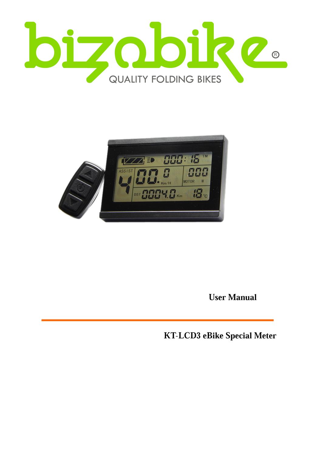
ELECTRIC BICYCLE METER KT LCD3 Product User Manual. User Manual. KT-LCD3 ebike Special Meter
 ELECTRIC BICYCLE METER KT LCD3 Product User Manual User Manual KT-LCD3 ebike Special Meter WWW.SZKTDZ.COM 1 Contents Preface...4 Outlook and Size..4 Meter Dimension.. 4 Button Box Dimension...5 Main Material
用户手册. KT-LCD6 ebike Special Meter
 用户手册 User Manual KT-LCD6 ebike Special Meter WWW.SZKTDZ.COM Contents Preface... 4 Outlook and Size... 4 Meter Dimension 4 Button Box Dimension.. 4 Main Material and Color.... 5 Wiring Schematic.. 5 Installation
广州谐同电子科技有限公司 Guangzhou Electrony Corporation 用户手册. User Manual. S-LCD3 ebike Special Meter
 广州谐同电子科技有限公司 Guangzhou Electrony Corporation 用户手册 User Manual S-LCD3 ebike Special Meter WWW.ELECTRONY.CN Contents Preface... 4 Outlook and Size... 4 MeterDimension 4 Button Box Dimension.. 4 Main Material
用户手册. User Manual. KT-LCD5 ebike Special Meter
 用户手册 User Manual KT-LCD5 ebike Special Meter WWW.SZKTDZ.COM Contents Preface... 3 Outlook and Size.. 3 Meter Dimension 3 Main Material and Color....... 3 Wiring Schematic. 3 Installation Instruction..
用户手册. User Manual. S-LCD8 ebike Special Meter
 用户手册 User Manual S-LCD8 ebike Special Meter WWW.BMSBATTERY.COM Contents Preface... 4 Outlook and Size... 4 Meter Dimension 4 Button Box Dimension..5 Main Material and Color.... 5 Wiring Schematic.. 5 Installation
用户手册. User Manual. KT-LCD2 ebike Special Meter
 用户手册 User Manual KT-LCD2 ebike Special Meter WWW.SZKTDZ.COM Contents Preface... 3 Outlook and Size... 3 Meter Dimension 3 Main Material and Color... 3 Wiring Schematic.. 3 Installation Instruction... 4
Table of content 1 Preface 18 2 Appearance and size Material and color Display size and installation size 19 3 Function summary and
 Table of content 1 Preface 18 2 Appearance and size.19 2.1 Material and color 19 2.2 Display size and installation size 19 3 Function summary and button definition 20 3.1 Preset and default items. 20 3.2
Manual. C500B LCD Instructions
 Manual C500B LCD Instructions CONTENT ABOUT THE USER MANUAL 3 OUTLOOK AND SIZE 3 MATERIAL AND COLOR 3 BUTTON DEFINITION 4 FUNCTION SUMMARY 5 FULL VIEW AREA 7 NORMAL VIEW AREA 7 NORMAL OPERATION 8 1.ON/OFF
Enoeco LCD Console CS-S900. User Manual V.2014
 Enoeco LCD Console CS-S900 User Manual V.2014 1. Exterior Parameters Casing Material: ABS Display Material: High Hardness Acrylic (the same hardness value as tempered glass). Front View Side View Side
1 LCD instructions. The figure of LCD display see below:
 1 LCD instructions The figure of LCD display see below: 1 1.1 Power On/Off Press and hold Power button for 2 seconds can turn on/off the Meter. The Meter will automatically shut down when there is no operation
C500B-LCD Instructions
 C500B-LCD Instructions Nanjing Bigstone Electronic & Technology co.,ltd CONTENT ABOUT THE USER MANUAL........ 3 OUTLOOK AND SIZE........ 3 MATERIAL AND COLOR 3 BUTTON DEFINITION..... 4 FUNCTION SUMMARY....
Product Specification
 Product Specification Product Mode TFT LCD Display APT TFT850C Abbreviation 850C Website www.elecycles.com 1 1. 2. 3. 4. Product Name TFT LCD display Model : APT TFT 850C Suppliers ELECYCLES Email : support@elecycles.com
C965 LCD Display User Manual
 C965 LCD Display User Manual Supplier Brighton E-bikes Ltd. Stanford Gate, South Road Brighton, East Sussex BN1 6SB TEL: 01273 930700 Email: brightonebikes@gmail.com www.brightonebikes.co.uk 1. Product
KING-METER KM5S LCD USERS GUIDE. 中文 1-31 页 English P32-64
 KING-METER USERS GUIDE KM5S LCD 中文 1-31 页 English P32-64 Contents About the User Manual 32 Appearance and Size 33 Material and Color 33 Function Summary and Button Definition 34 Function Summary 34 Monitor
LCD Display CS-850. User Manual V.2014
 LCD Display CS-850 User Manual V.2014 1. Exterior Parameters Casing Material: ABS Display Material: High Hardness Acrylic (the same hardness value as tempered glass). Front View Side View Side View of
Product Specification
 Product Specification 04/2018 Product Mode TFT LCD Display APT TFT850C Abbreviation 850C Client Customer audit Supplier Tianjin APT Science and Technology Co., Ltd. 1001, Building 5 HuaDing, No.1 HuaKe
Contents. Product name and model... 1 Specifications... 1 Appearance and Size... 1 Function Summary and Button Definition... 2 Function Summary...
 Contents Product name and model... 1 Specifications... 1 Appearance and Size... 1 Function Summary and Button Definition... 2 Function Summary... 2 Button Definition... 2 Assembly... 2 Function Area Distribution...
Product Specification
 Product Specification January 2018 Product Model TFT LCD Display 850C (DPC-14) Abbreviation 850C-BF Brighton E-bikes. 2 nd Floor Southgate South Road Brighton Tel Email TEL: 01273 930700 Brightonebikes@gmail.com
KING-METER USERS GUIDE J-LCD
 KING-METER USERS GUIDE J-LCD GUIDE 中文 1-15 页 English P/16-32 0 Contents 1 Preface.18 2 Appearance and Size.19 2.1 Material and color 19 2.2 Display Size and Installation Size 19 3 Function Summary and
Assistance Level option... 9 PAS Ratio Settings Controller Over-Current Cut Settings Power Assistant Sensor Settings...
 Content Product name and model... 1 Specifications... 1 Appearance and Size... 1 Color categories... 1 Function Summary and Button Definition... 1 Function Summary... 1 Functional Area Distribution...
EVBIKE LCD display C965 User manual
 EVBIKE LCD display C965 User manual WWW.EV-POWER.EU - 1 - Contens: 1/ INFORMATION 2/ BASE SETTINGS 3/ ADVANCE SETTINGS 4/ ERROR CODES 5/ INSTALATION Thank you for purchasing EVBIKE product and we hope
Product Specification
 Product Specification 12/2015 Product Mode Middle install intelligent LCD Display APT12LCD800S Abbreviation 800S Client Customer audit Supplier Tianjin APT Development Co., Ltd. Room 609, Hi-tech Building
Product Specification
 Product Specification Product Mode Abbreviation 750C Client Supplier TFT LCD Display 750C E-Drive E-Drive onderdeel van E.F.U. B.V. . Product ame TFT LCD display Model : TFT 750C 2. Suppliers E-Drive 3.
Product Specification
 Product Specification 12/2012 Product Mode Middle install intelligent LCD Meter APT12LCD800U Abbreviation 800U Client Customer audit Supplier Tianjin APT Development Co., Ltd. Room 609, Hi-tech Building
Contents. Product name and model... 1 Specifications... 1 Appearance and Size... 1 Function Summary and Button Definition...2 Function Summary...
 Contents Product name and model... 1 Specifications... 1 Appearance and Size... 1 Function Summary and Button Definition...2 Function Summary... 2 Button Definition...2 Assembly...2 Function Area Distribution...2
Product Specification and manual
 Product Specification and manual Product Mode Dillenger C965 APT12LCD800S Supplier Dillenger OEM Factory 3, 13 Olympic Circuit Southport QLD 4215 Australia 1 Product Name 1.1 Dillenger C965 1.2 Model:APT12LCD800S
Product Specification
 Product Specification 07/2013 Product Mode Middle install intelligent LCD Display APT12LCD800S Abbreviation 800S Client Customer audit Supplier Tianjin APT Development Co., Ltd. Room 609, Hi-tech Building
DP C10.UART CONTENT Content Normal indication area Introduction Button definition Appearances and dimensions Normal operation Specifications
 CONTENT DP C10.UART CONTENT Content 1 Introduction 2 Appearances and dimensions 3 Specifications 4 Functional overview 5 Normal indication area 6 Button definition 7 Normal operation 7 Parameter setting
VLCD-5. VLCD-5 Display Instrument Operation Manual
 VLCD-5 VLCD-5 Display Instrument Operation Manual CATALOG Summarize... 1 Specification... 1 Installation... 2 Function Description... 3 Operation Flow... 4 5.1 Button Definition... 4 5.2 Operation and
Product Specification
 Product Specification 05/2014 Product Mode Middle install intelligent LCD Display APT12LCD800CAN Abbreviation 800S Client Customer audit Supplier 1001, Building 5 HuaDing, No.1 HuaKe 3 Road, Binhai hi-tech
User manual E-CITY 5.5 E-COUNTRY 5.5. Enjoy your ride! BATTERY: SAMSUNG CELL 13-16Ah MOTOR: BAFANG 250W 36V
 User manual E-CITY 5.5 E-COUNTRY 5.5 Enjoy your ride! www.crussis.cz BATTERY: SAMSUNG CELL 13-16Ah MOTOR: BAFANG 250W 36V Content Product name and model...1 Specifica ons...1 Appearance and Size...1 Color
Content. Product Name and Model... 1 Specifications... 1 Appearance and Size... 1 Function Summary... 2
 Content Product Name and Model... 1 Specifications... 1 Appearance and Size... 1 Function Summary... 2 Function Summary... 2 Functional Area Distribution... 3 General Operation... 3 Switching the ebike
Product Specification
 Product Specification 11/2013 Product Mode Middle install intelligent LCD Display APT13LCD450U Abbreviation 450U Client Customer audit Supplier Tianjin APT Development Co., Ltd. Room 609, Hi-tech Building
1. Product Name. 2. Electrical Parameters. 3. Dimensions & Material. 4. Features. ! TFT LCD display. ! Model : DPC14. ! 3.
 1. Product Name! TFT LCD display! Model : DPC14 2. Electrical Parameters! 3.2 inch IPS screen! 24V/36V/48V battery supply! Rated operating current : 40mA! Max operating current : 100mA (36V battery, with
YUYANGKING Controller User Manual Bluetooth version
 YUYANGKING Controller User Manual Bluetooth version 1.1 Download the Yuyangking App from Google Play or App store, Android version need system newer than 4.4.4 1.2 Start the YUYANG KING controller electric
User Manual. Borescope. Model THE STANDARD IN PRECISION MEASUREMENT
 User Manual Model 20250-28 Borescope THE STANDARD IN PRECISION MEASUREMENT Introduction The Digi-Sense Borescope (Model 20250-28) is ideal for the inspection of ductwork, wiring locations, piping, vehicles,
DP E12.UART CONTENT CONTENT. Content 1. Normal indication area 6. Button definition 7. Introduction 2. Normal operation 7. Overview drawing 3
 CONTENT DP E12.UART CONTENT Content 1 Introduction 2 Overview drawing 3 Specifications 4 Functional overview 5 Normal indication area 6 Button definition 7 Normal operation 7 Error code definition 8 DISPLAY
SPA DESIGN MICROPROCESSOR SPEEDO MANUAL
 SPA DESIGN MICROPROCESSOR SPEEDO MANUAL SPA DESIGN MICROPROCESSOR SPEEDO INSTALLATION AND OPERATING MANUAL CONTENTS PAGE 2...INSTRUMENT FEATURES. PAGE 3...INSTALLATION DETAILS. PAGE 4...OPERATING INSTRUCTIONS.
Loup Electronics Planter Monitor LPM II. User Guide
 Loup Electronics Planter Monitor LPM II User Guide TABLE OF CONTENTS 1. I TRODUCTIO...4 2. LIQUID CRYSTAL DISPLAYS...8 2.1 UPPER LCD...8 2.2 LOWER LCD...9 3. OPERATI G SPECIFICATIO...10 3.1 OPERATING MODES...10
VR2 R-NET LED R-NET LCD. Controller System Operation
 VR2 R-NET LED R-NET LCD Controller System Operation 1.VR2 Controller Operation 1.1 Controls/JSM 1.2 Button/Indicator 1.3 Control System Status indication 1.4 Module Wiring 1.5 VR2 Locking / Unlocking The
User Manual Video Borescope Model
 User Manual Video Borescope Model 20250-27 THE STANDARD IN PRECISION MEASUREMENT Introduction The Digi-Sense Video Borescope (Model 20250-27) is ideal for the inspection of ductwork, wiring locations,
For more information on these functions and others, please refer to the EDC User s Manual.
 EDC Handheld Device Guide BASIC FUNCTION When using the handheld controller, please set the dial switch to 0 on the front side of the panel of the EDC Controller. This will allow the user to have access
Thank you for choosing SPRINT
 USER MANUAL Thank you for choosing SPRINT GPS cycling computer With low power consumption 2.7 inches HD screen More than 30 hours of battery life Integrated accelerometer, geomagnetic Temperature and air
Tuff Tread. Page 1 of 7
 Calibration & Setup For 4600PR, 4600PRC and 4600HRT Models NOTE: After you begin either of the calibration processes or the advanced parameter setup process, you must complete the process by pressing ENTER
Contents LOCAL MANAGEMENT LOGIN INTERFACE RECORD SEARCH: LOG SEARCH SYSTEM STATUS BASIC SETUP.
 User Manual For MD AHD MDVR Copyright 2013-2016, Howen Technology Co., Ltd All Rights Reserved 1-59 Contents 1. 2. LOCAL MANAGEMENT... 3 2.1. LOGIN INTERFACE... 3 2.2. RECORD SEARCH:...6 2.3. LOG SEARCH...
iobd2 MFi BT VAG Adapter User Manual
 iobd2 MFi BT VAG Adapter User Manual VW, AUDI, SKODA, SEAT Preface Thank you for using this product. Please read instructions carefully before operating this unit. This manual guides the users how to operate
WUHAN QIWU TECHNOLOGY CO., LTD
 USER MANUAL igs20e GPS CYCLING COMPUTER www.igpsport.com WUHAN QIWU TECHNOLOGY CO., LTD 1. STANDARD PACKAGE INCLUDES igs20e x1 Micro USB Cable x1 User Manual x1 Standard Bike Mount x2 Bike Mount Pad x2
VIBRATION METER Model : VB-8213
 Acceleration/Velocity/Displacement RMS/Peak/Max. Hold, Metric & Imperial unit VIBRATION METER Model : VB-8213 Your purchase of this VIBRATION METER marks a step forward for you into the field of precision
- English - Digital Wireless Computer User s Manual
 - English - Digital Wireless Computer User s Manual Table of contents 1 Preface 8 Set bike & wheel size 14 Operation in sensor mode 2 Package contents 9 Set units & odometer 15 Operation in phone mode
MTP INSTRUCTION MANUAL
 MTP INSTRUCTION MANUAL Wireless Electricity Monitor Model MTP-3100 MTP Instruments Inc. Table of Content 1. Introduction Page 1 2. Safety and Maintenance Information Page 1 3. Features / Specifications
FG-7000L Digital Force Gauge Operation Manual
 FG-7000L Digital Force Gauge Operation Manual Operators should wear protection such as a mask and gloves in case pieces or components break away from the unit under test. Whether the unit is ON or OFF,
SHIMPO INSTRUMENTS. FG-7000T Digital Torque Gauge Operation Manual
 FG-7000T Digital Torque Gauge Operation Manual SHIMPO INSTRUMENTS Operators should wear protection such as a mask and gloves in case pieces or components break away from the unit under test. Whether the
Content. Introduction. Reset Computer. Set Unit. Heart Rate. Set Smart EL. Reset Trip Data. Unit. Calories. Enter Setting Mode.
 - English - Content 1 Introduction Reset Computer Set Unit Heart Rate 3 Unit Reset Trip Data 27 Set Smart EL Calories Parts 17 Enter Setting Mode 29 Mode / Sub Mode Functions 37 Average 5 Installation
970 Serials Lights. Multi-Function Lights System FEATURES SPECIFICATION
 970 Serials Lights Multi-Function Lights System FEATURES Suitable for Marine & Vehicle Easy to install & Easily relearning Remote Unit Wide Range Rotation movement. Dual Function Control with Wire Control
Tuff Tread. Grade Calibration
 Calibration Instructions Version 1.9 Display Board NOTE: After you begin either of the calibration processes or the advanced parameter setup process, you must complete the process by pressing STOP repeatedly
Pen Vibration Meter. User's Guide. Model VB Washington Street Melrose, MA Phone Toll Free
 User's Guide 99 Washington Street Melrose, MA 02176 Phone 781-665-1400 Toll Free 1-800-517-8431 Visit us at www.testequipmentdepot.com Pen Vibration Meter Model VB400 Introduction Congratulations on your
Table of Contents Introduction Specifications Power supply: Operating temperature: Size: Display Data: Resolution: Ranges:
 SW RP07 Table of Contents Introduction.............................. 3 Specifications............................. 4 Installation................................5 Operation.................................7
Page 1. MILLION CONCEPT ELECTRONIC (SHENZHEN) CO., LTD. Functional Operation Specification of Product. 3D electronic paper step counter watch
 CO., LTD. Functional Operation Specification of Product. 3D electronic paper step counter watch") Model Prepared by Zou Linlin W286 MILLION CONCEPT ELECTRONIC (SHENZHEN) CO., LTD. Functional Operation Specification of Product Development project 3D electronic paper step counter watch Version V6 Date
Model Prepared by Zou Linlin W286 MILLION CONCEPT ELECTRONIC (SHENZHEN) CO., LTD. Functional Operation Specification of Product Development project 3D electronic paper step counter watch Version V6 Date
WAKE UP AND SLEEP. ubber Ties x 4. Auto Wake Up: When there is any speed or vibration, the computer will wake up.
 MINIAC GPS-333 CYCLING COMPUTER INSTRUCTIONS Thank you for purchasing an MSW Miniac GPS-333 Cycling! ALT GAIN Place LOSS on the bracket Gradient Maximum ALT Total ALT thealt computer and secure it by turning
5.6" Multi-function Monitor
 5.6" Multi-function Monitor User s Manual Please read this Manual carefully before use of this product, and keep it handy for future reference. I. Packing List.. 2 II. Product Appearance... 3-5 III. Product
Digital Air Velocity Meter DC580. The Value Leader TM
 Digital Air Velocity Meter DC580 The Value Leader TM www.testproductsintl.com Contents Introduction... Page 1 General Overview & Guidelines... Page 1 Features and Guidlines... Page 2 LCD Overview... Page
INSTRUCTION MANUAL. Remote Meter: MT50
 INSTRUCTION MANUAL Remote Meter: MT50 Thank you very much for selecting our product! This manual offers important information and suggestions with respect to installation, use and troubleshooting, etc.
Abstract. GLV User Manual 1
 GLV User Manual 1 Abstract This user manual is a high level document that explains all operational procedures and techniques needed to operate the GLV system in a safe and effective manner. Anyone operating
Streetlight Management System Operating instructions
 Streetlight Management System Operating instructions InnoSmart-BS-V03 June 20 2017 TM The Internet of things is creating a new world! 1 Thank you for purchasing our company's products, if you have any
MEGA DIAL PANEL Instructions
 2036 Fillmore Street Davenport, Ia. 52804 563-324-1046 www.racedigitaldelay.com MEGA DIAL PANEL Instructions WARRANTY AND DISCLAIMER DIGITAL DELAY ELECTRONICS INC. WARRANTS THE PRODUCTS IT MANUFACTURES
Installation Guide Solid State Meter
 Installation Guide Solid State Meter Document version v0.2 February 2018 1 Where Intelligence Meets Infrastructure TM Contents About this Installation Guide... 3 Transport and storage... 3 Installation
STEP MOTOR DRIVER SMD-4.2DIN
 SMART MOTOR DEVICES http://www.smd.ee STEP MOTOR DRIVER SMD-4.2DIN manual SMDDIN.42.001 2018 1. Product designation Step motor controller SMD-4.2DIN is an electronic device designed to operate with 2 or
OEM. Room unit QAA822 with2- wire interface. Building Technologies CLIMATIX TM. For use with Climatix controllers
 OEM CLIMATIX TM Room unit QAA822 with2- wire interface For use with Climatix controllers Remote control of air conditioning unit Mandík Measurement of the room temperature Buttons for starting, setting
Phoebe LED Spectrum 10W RGB/Tuneable White downlight INSTALLATION AND APP INSTRUCTIONS
 Phoebe LED Spectrum 10W RGB/Tuneable White downlight INSTALLATION AND APP INSTRUCTIONS Contents 1. Product Installation...4 2. Space Requirements & Wiring Diagram...6 3. App Set-up & Adding Lights...7
4-Channel Vibration Datalogger
 User's Guide 99 Washington Street Melrose, MA 02176 Phone 781-665-1400 Toll Free 1-800-517-8431 Visit us at www.testequipmentdepot.com 4-Channel Vibration Datalogger Model VB500 Introduction Congratulations
GMOS JI100S QUICK GUIDE. Dashboard Unit Location. Installing Bracket. Clicking Device into Place. No, unless with external antenna.
 GMOS JI100S QUICK GUIDE Dashboard Unit Location Best No, unless with external antenna Installing Bracket With 3M Dual Lock tape Apply the included tape to the back of the bracket, and adhere the bracket
POWERHOUSE. -- the finest in Digital Command Control -- PRODUCT MANUAL FOR PB-205a DUAL 5AMP POWER STATION
 POWERHOUSE TM -- the finest in Digital Command Control -- PRODUCT MANUAL FOR PB-205a DUAL 5AMP POWER STATION NCE Corporation 1260 CREEK STREET SUITE 100 WEBSTER NEW YORK 14580 FAX : (716) 671-9337 E-mail:
Vision Fitness TF20-TF40-T40 Frame with Classic / Elegant / Touch Console Service Manual
 Vision Fitness TF20-TF40-T40 Frame with Classic / Elegant / Touch Console Service Manual 1 TABLE OF CONTENTS CHAPTER 1: SERIAL NUMBER LOCATION 1.1 Serial Number Location - TF20 Frame.....3 1.2 Serial Number
Guide Specification for 3G Wireless Battery Monitoring System
 Guide Specification for 3G Wireless Battery Monitoring System 3/11A FirstLine Wireless BMS 1 1.0 Scope This specification defines the minimum requirements for a predictive FirstLine Wireless Battery Monitoring
Wired Cycle Computer Instruction Manual
 Wired Cycle Computer Instruction Manual Contents: 1. Supply 2. Assembly / Instructions 3. Keys & Functions 4. Modes 5. LCD Display 6. Basic Operations 7. Wheel Size 8. General Settings 9. Reset 10. Battery
User's Guide. Vane Thermo-Anemometer Datalogger. Model Introduction
 User's Guide Vane Thermo-Anemometer Datalogger Model 451126 Introduction Congratulations on your purchase of Extech's Thermo-Anemometer Datalogger. This Vane-type Anemometer can indicate Air Velocity in
ISSPRO 3 3/8" DIAMETER PROGRAMMABLE SPEEDOMETER Air Core Version
 GENERAL INFORMATION: Operating Voltage: Input: Magnetic sensor or AC generator Transient Protection: +100 V, -400 V Reverse Voltage Protected ISSPRO 3 3/8" DIAMETER PROGRAMMABLE SPEEDOMETER Air Core Version
USB-5100 Series Multi-Channel Data Loggers
 Multi-Channel Data Loggers Features Stand-alone, remote multi-channel data loggers The USB-5104 is a high-accuracy, four-channel thermocouple data logger that records temperature in indoor environments
REMOTE METER. Model: MT50 INSTRUCTION MANUAL
 REMOTE METER Model: MT50 INSTRUCTION MANUAL For use with solar charge controllers PU series, LS series, VS series, PTR series, Tracer MPPT series and other compatible controllers Remote Meter MT50 Please
VB Model. Instruction Manual. Vibration Meter. reedinstruments. www. com
 Model Vibration Meter Instruction Manual VB-8200 reedinstruments com Table of Contents Features... 3 Specifications...4-5 Instrument Description... 6 Operating Instructions...5-10 PEAK value... 6 Data
 ENGLISH Installation video Operating video Settings video www.vdocyclecomputing.com/service Preface Congratulations In choosing a VDO computer, you have opted for high-quality device with first rate technology.
5450 NW 33rd Ave, Suite 104 Fort Lauderdale, FL Fruitland Ave Los Angeles, CA UM Channel Monitor.
 5450 NW 33rd Ave, Suite 104 Fort Lauderdale, FL 33309 3211 Fruitland Ave Los Angeles, CA 90058 UM-600 6-Channel Monitor Version 2 Installation and Operation Manual Rev. G P/N145F-12990 PCO 00007462 (c)
Digital Torque Gauge. User s Manual
 Digital Torque Gauge User s Manual Content 1. Introduction 1.1 Overview 1 1.2 Indicator 2 1.3 Torque Sensor 3 1.4 Specifications 4 2. Operation 2.1 Test Preparation 5 2.2 Power on/off 5 2.3Testing 5 2.3.1
medemagroup Joystick DX2 User guide P Q ver October 2011
 medemagroup P9-0290-Q ver. 1.0.2 - October 2011 GB User guide Joystick DX2 Quick guide P9-0290-Q 2 of 16 Version 1.0.2/2011 Contents Introduction...4 Joystick parts...5 Operating...5 Clock on/off...6 Set
BEP 600-ACSM AC SYSTEMS MONITOR. Installation and Operating Instructions. Page 1
 BEP 600-ACSM AC SYSTEMS MONITOR Installation and Operating Instructions Page 1 This page has been deliberately left blank Page 2 Table of Contents 1. BASICS 4 WARNING AND CAUTION 4 WARNING 4 CAUTION 4
INSTALLATION DKM-409 NETWORK ANALYSER WITH HARMONIC MEASUREMENT AND SCOPEMETER. Before installation:
 DKM-409 NETWORK ANALYSER WITH HARMONIC MEASUREMENT AND SCOPEMETER The DKM-409 is a precision instrument designed for displaying various AC parameters in 3-phase distribution panels. Thanks to its isolated
VER Tunturi F30, E40, E45, E60, E80 & E85
 VER. 0.90 Tunturi F30, E40, E45, E60, E80 & E85 1 FOREWORD This Service Manual contains instructions and advice on service procedures for Tunturi bike ergometers E30, E40, E45, E60, E80 and E85 (the mechanical
ISF-1DF SERIES DIGITAL FORCE GAGE OPERATION MANUAL
 ISF-1DF SERIES-E www.insize.com ISF-1DF SERIES DIGITAL FORCE GAGE OPERATION MANUAL V0 Attention Description Regardless of whether the unit is ON or OFF, Don t exceed the capacity of the gauge. At 110%
VANTAGE CL1. Installation and use of the CL1 Karting Data Kit
 Installation and use of the CL1 Karting Data Kit Table of Contents What s in the box 3 Items needed for installation 4 CL1 registration 5 D3 app install 6 Battery installation 7 Mounting the CL1 data box
Gladiator Lift Services Ltd OPTIO MRL Controller Specification
 Gladiator Lift Services Ltd OPTIO MRL Controller Specification 1 Control System Specification General Requirements Control Cabinet A new MRL control panel shall be provided being of the enclosed steel
GENERAL DESCRIPTION... 1 INSTALLATION... 2 CONNECTIONS... 3 OVERVIEW... 6 AREA & SPEED METER SETUP (WIZARD)... 9
... 9") TABLE OF CONTENTS For Serial Numbers 30007000-7999 GENERAL DESCRIPTION... 1 INSTALLATION... 2 CONNECTIONS... 3 OVERVIEW... 6 AREA & SPEED METER SETUP (WIZARD)... 9 AREA & SPEED METER USING GPS SETUP (WIZARD)...
TABLE OF CONTENTS For Serial Numbers 30007000-7999 GENERAL DESCRIPTION... 1 INSTALLATION... 2 CONNECTIONS... 3 OVERVIEW... 6 AREA & SPEED METER SETUP (WIZARD)... 9 AREA & SPEED METER USING GPS SETUP (WIZARD)...
SlimLine. Compliant to DO-160D. Document # Rev G. www. rosenaviation.com. www. rosenaviation.com
 6.5 Model DISPLAY SlimLine Number 6500 www. rosenaviation.com CORPORATE OFFICE 1020 Owen Loop South Eugene, OR 97402 1-888-668-4955 Fax (541) 342-4912 6500 www. rosenaviation.com Document # 9002751 Rev
Robolab. Table of Contents. St. Mary s School, Panama. Robotics. Ch. 5: Robolab, by: Ernesto E. Angulo J.
 Robolab 5 Table of Contents Objectives...2 Starting the program...2 Programming...3 Downloading...8 Tools...9 Icons...9 Loops and jumps...11 Multiple tasks...12 Timers...12 Variables...14 Sensors...15
EnCell Battery Cell Monitor
 EnCell Battery Cell Monitor Instruction Manual Model RCM15S12 NERC Compliant YO R U H T PA TO Z O R E W O D N M I T E enchargepowersystems.com sales@enchargepowersystems.com (888) 407.5040 Contents 1 Warnings,
Stepper Motor Driver Board. Instruction Note
 Stepper Motor Driver Board Instruction Note August 31, 2012 General Photonics Corp. Ph: (909) 590-5473 5228 Edison Ave. Fax: (909) 902-5536 Chino, CA 91710 USA www.generalphotonics.com Document #: GP-IN-MDL-003-CONTROLB-10
Sidewinder Pumps Inc. AC Timer/Controller
 Sidewinder Pumps Inc. AC Timer/Controller Page 1 of 12 Rev 032417 Table of Contents 1. Warnings-------------------------------------------------------------------------------------------------- 3 1.1.
M2 OLED Temperature Monitor Instructions PN 1841
 M2 OLED Temperature Monitor Instructions PN 1841 Installation Checklist Check for components included Read Warning and Cautions Read page 3 for mounting instructions Read System Overview, Mounting Considerations,
C Mon diagnostic tool quicktour C mon description and features
 C Mon diagnostic tool quicktour C mon description and features 12 13 14 6 11 10 9 7 8 1 4 2 1 - Button #1 2 - Button #2 3 - Button #3 4 - Button #4 5 - Power switch 6 - LCD screen 7 - Busy led 8 - Power
Date 18/05/17. Operation and maintenance instructions for driver configurator QSet
 Operation and maintenance instructions 28 1. General recommendations The recommendations regarding safe use in this document should be observed at all times. Some hazards can only be associated with the
Large Vane CFM/CMM Thermo-Anemometer
 User Manual Large Vane CFM/CMM Thermo-Anemometer Model AN300 Additional User Manual Translations available at www.extech.com Introduction Congratulations on your purchase of the Extech AN300 Vane Airflow