USER S MANUAL. C68 KFLOP MOTHERBOARD Rev. 3 JANUARY 2015.
|
|
|
- Belinda Hawkins
- 6 years ago
- Views:
Transcription

1 USER S MANUAL C68 KFLOP MOTHERBOARD Rev. 3 JANUARY 2015.
2 USER'S MANUAL TABLE OF CONTENTS Page # Contents 1.0 OVERVIEW FEATURES BOARD DESCRIPTION SELECT JUMPER DEPENDING OF THE AXIS THAT FENCE TO USING SPECIFICATIONS Power Requirements Supported Connection PINOUT Connectors Connectors of the KFLOP (JP4, JP6 y JP7) Connectors of (LPT_1, LPT_2 y Expansion) LPT_ LPT_ EXPANSION DIMENSIONS... 8 User s Manual Page 0
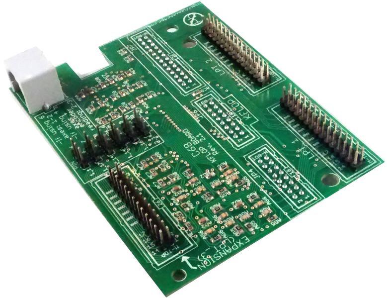
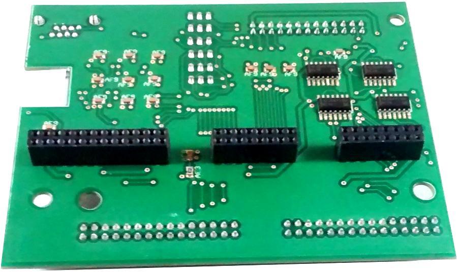
3 1.0 OVERVIEW This is a motherboard for the KFLOP. Breakout boards can be connected to this motherboard providing different types of Inputs / Outputs and features. 2.0 FEATURES Designed for KFLOP Motion Controller 2 Expansion ports to connect breakout boards (C23, C25, C32 and C62) for motion control functions. 1 Expansion ports to connect breakout boards. RJ45 of Input to connect with RJ45 of the KFLOP. User s Manual Page 1

4 3.0 BOARD DESCRIPTION User s Manual Page 2


5 4.0 SELECT JUMPER DEPENDING OF THE AXIS THAT FENCE TO USING If going to work 4 axes with encoder reading, the pin 14 of port 1 would work as PWM and the pin 16 of port 1 as DIRECTION. Use jumper as sample to continuation If going to work 6 axes, the pin 14 the port 1 would work as axis. Use jumper as sample to continuation 5.0 SPECIFICATIONS 5.1 Power Requirements This board is powered with 5V for medium the KFLOP, feeding the expansion port. To the C32 not fed, because the C32 maintains 5v by the pin 26 of port 1, in the C68 the pin 26 of port 1 this to air, for that when connecting the C32 not cause a circuit short in the board. User s Manual Page 3
 (26 Pin) The connector JP5 (RJ45), the pines 1, 2 y 3 you have that selecting LPT_1 (Port_1) or EXPANSION (Port_3), depending on the number of axes that")
6 5.2 Supported Connection Compatible breakout and expansion boards Board LPT_1 LPT_2 C23 X X C25 X X C32 X X C62 X X 6.0 PINOUT 6.1 Connectors Connectors of the KFLOP (JP4, JP6 y JP7) (16 Pin) (26 Pin) JP5 (Connector RJ45) Connectors of (LPT_1, LPT_2 y Expansion) (26 Pin) The connector JP5 (RJ45), the pines 1, 2 y 3 you have that selecting LPT_1 (Port_1) or EXPANSION (Port_3), depending on the number of axes that are using. (4 axes o 6 axes). In the PINOUT of the ports is repeats the pines of connector JP5 (RJ45) JP5_ P1_1 / P3_6 JP5_ P1_17 / P3_7 JP5_ P1_14 / P3_8 GLOSSARY: PN_M P=port N=num of port M=num of pin User s Manual Page 4
7 6.2 LPT_1 LPT_1 Equivalent P.P. Pin KFLOP Functions I/O Connector KFLOP KFLOP Pin P1_1 4 output) or (Encoder 4 Input Phase A) Output JP5_1 IO36 P1_2 Gen Purpose LVTTL I/O (5V Tolerant) or Axis 0 Home (or Step 0 output) Output JP7_15 IO8 P1_3 Gen Purpose LVTTL I/O (5V Tolerant) or Axis 1 Home (or Dir 0 output) Output JP7_16 IO9 P1_4 Gen Purpose LVTTL I/O (5V Tolerant) or Axis 2 Home (or Step 1 output) Output JP7_17 IO10 P1_5 Gen Purpose LVTTL I/O (5V Tolerant) or Axis 3 Home (or Dir 1 output) Output JP7_18 IO11 P1_6 Gen Purpose LVTTL I/O (5V Tolerant) or Axis 0 + Limit (or Step 2 output) Output JP7_19 IO12 P1_7 Gen Purpose LVTTL I/O (5V Tolerant) or Axis 0 - Limit (or Dir 2 output) Output JP7_20 IO13 P1_8 Gen Purpose LVTTL I/O (5V Tolerant) or Axis 1 + Limit (or Step 3 output) Output JP7_21 IO14 P1_9 Gen Purpose LVTTL I/O (5V Tolerant) or Axis 1 - Limit (or Dir 3 output) Output JP7_22 IO15 P1_10 Gen Purpose LVTTL I/O (5V Tolerant) or Encoder 0 Input Phase A Input JP7_7 IO0 P1_11 Gen Purpose LVTTL I/O (5V Tolerant) or Encoder 1 Input Phase A Input JP7_9 IO2 P1_12 Gen Purpose LVTTL I/O (5V Tolerant) or Encoder 1 Input Phase B Input JP7_10 IO3 P1_13 Gen Purpose LVTTL I/O (5V Tolerant) or Encoder 2 Input Phase A Input JP7_11 IO4 P1_14 5output) or (Encoder 5 Input Phase A) / Gen Purpose LVTTL I/O (3.3VOnly) or PWM1 out Output JP5_3/JP6 _6 IO38/IO 27 P1_15 Gen Purpose LVTTL I/O (5V Tolerant) or Encoder 0 Input Phase B Input JP7_8 IO1 P1_16 Gen Purpose LVTTL I/O (5V Tolerant) or (or Dir 5output) or (Encoder 5 Input Phase B) Output JP5_4 IO39 P1_17 Gen Purpose LVTTL I/O (5V Tolerant) or (or Dir 4output) or (Encoder 4 Input Phase B) Output JP5_2 IO37 P1_18 Digital Ground GND JP7_25/26 GND User s Manual Page 5
8 6.3 LPT_2 LPT_2 Equivalent P.P. Pin KFLOP Functions I/O Connector KFLOP KFLOP Pin P2_1 Gen Purpose LVTTL I/O (3.3V Only) Output JP7_5 IO44 Gen Purpose LVTTL I/O (5V Tolerant) or Encoder 3 P2_2 Input Phase A Input JP7_13 IO6 Gen Purpose LVTTL I/O (5V Tolerant) or Encoder 3 P2_3 Input Phase B Input JP7_14 IO7 P2_4 Gen Purpose LVTTL I/O (3.3V Only) Input JP4_5 IO16 P2_5 Gen Purpose LVTTL I/O (3.3V Only) Input JP4_6 IO17 P2_6 Gen Purpose LVTTL I/O (3.3V Only) Input JP4_7 IO18 P2_7 Gen Purpose LVTTL I/O (3.3V Only) Input JP4_10 IO19 P2_8 Gen Purpose LVTTL I/O (3.3V Only) Input JP4_11 IO20 P2_9 Gen Purpose LVTTL I/O (3.3V Only) Input JP4_12 IO21 P2_10 Gen Purpose LVTTL I/O (3.3V Only) Input JP4_13 IO22 P2_11 Gen Purpose LVTTL I/O (3.3V Only) Input JP4_14 IO23 P2_12 Gen Purpose LVTTL I/O (3.3V Only) Input JP4_15 IO24 P2_13 Gen Purpose LVTTL I/O (3.3V Only) Input JP4_16 IO25 P2_14 Gen Purpose LVTTL I/O (3.3V Only) or PWM0 out Output JP6_5 IO26 P2_15 Gen Purpose LVTTL I/O (3.3V Only) or PWM1 out Input JP6_16 IO35 P2_16 Gen Purpose LVTTL I/O (3.3V Only) or PWM2 out Output JP6_7 IO28 P2_17 Gen Purpose LVTTL I/O (3.3V Only) or PWM3 out Output JP6_10 IO29 P2_18 GND GND GND GND User s Manual Page 6
9 6.4 EXPANSION EXPANSION (LPT_3) Equivalent P.P. Pin KFLOP Functions I/O Connector KFLOP KFLOP Pin P3_1 Gen Purpose LVTTL I/O (3.3V Only) Output JP7_6 IO45 P3_2 6output) or (Encoder 6 Input Phase A) Input JP5_5 O40 P3_3 6output) or (Encoder 6 Input Phase B) Input JP5_6 IO41 P3_4 7output) or (Encoder 7 Input Phase A) Input JP5_7 IO42 P3_5 7output) or (Encoder 7 Input Phase B) Input JP5_8 IO43 P3_6 4output) or (Encoder 4 Input Phase A) Input JP5_1 IO36 P3_7 4output) or (Encoder 4 Input Phase B) Input JP5_2 IO37 P3_8 5output) or (Encoder 5 Input Phase A) Input JP5_3 IO38 P3_9 NOT USE NOT USE NOT USE NOT USE Gen Purpose LVTTL I/O (5V Tolerant) or Encoder 2 P3_10 Input Phase B Input JP7_12 IO5 P3_11 Gen Purpose LVTTL I/O (3.3V Only) or PWM4 out Input JP6_11 IO30 P3_12 Gen Purpose LVTTL I/O (3.3V Only) or PWM5 out Input JP6_12 IO31 P3_13 Gen Purpose LVTTL I/O (3.3V Only) or PWM6 out Input JP6_13 IO32 P3_14 Gen Purpose LVTTL I/O (3.3V Only) or PWM7 out Output JP6_14 IO33 P3_15 Gen Purpose LVTTL I/O (3.3V Only) or PWM8 out Input JP6_15 IO34 P3_16 NOT USE NOT USE NOT USE NOT USE P3_17 NOT USE NOT USE NOT USE NOT USE P3_18 GND GND GND GND User s Manual Page 7

10 7.0 DIMENSIONS All dimensions are in Millimeters. DISCLAIMER Use caution. CNC machines can be dangerous machines. Neither DUNCAN USA, LLC nor Arturo Duncan are liable for any accidents resulting from the improper use of these devices. This board is not a fail-safe device and it should not be used in life support systems or in other devices where its failure or possible erratic operation could cause property damage, bodily injury or loss of life. User s Manual Page 8
USER S MANUAL VER.1. C34GV BOARD Rev. 1
 USER S MANUAL VER.1 C34GV BOARD Rev. 1 JANUARY, 2017 USER'S MANUAL TABLE OF CONTENTS Contents Page # 1.0 OVERVIEW... 1 2.0 FEATURES... 1 3.0 BOARD DESCRIPTION... 2 4.0 SPECIFICATIONS... 2 4.1 Power Requirements...
USER S MANUAL. M16 POKEYS MOTION MOTHERBOARD Rev. 1.1 JUNE 2016.
 USER S MANUAL M16 POKEYS MOTION MOTHERBOARD Rev. 1.1 JUNE 2016. USER'S MANUAL TABLE OF CONTENTS Page # Contents 1.0 OVERVIEW... 1 2.0 FEATURES... 1 3.0 BOARD DESCRIPTION... 2 4.0 SPECIFICATIONS... 2 4.1
USER S MANUAL VER.2. C76- MULTIFUNCTION CNC BOARD Rev. 1.4
 USER S MANUAL VER.2 C76- MULTIFUNCTION CNC BOARD Rev. 1.4 MARCH 2018 User s Manual Page i USER'S MANUAL TABLE OF CONTENTS Contents Page # 1.0 FEATURES... 1 2.0 I/O SPECIFICATIONS... 2 3.0 BOARD DESCRIPTION...
USER S MANUAL. E6 POKEYS MOTION CONTROLLER CNC INTERFACE DB25 Rev.1
 USER S MANUAL E6 POKEYS MOTION CONTROLLER CNC INTERFACE DB25 Rev.1 April, 2013 USER'S MANUAL TABLE OF CONTENTS Page # Contents 1.0 FEATURES... 2 2.0 SPECIFICATIONS... 3 3.0 SYSTEM REQUIREMENTS... 3 4.0
USER S MANUAL. CNC Servo Stepper Motor Control Box CH4EV12-1 Rev. 1
 USER S MANUAL CNC Servo Stepper Motor Control Box CH4EV12-1 Rev. 1 January, 2013 i USER'S MANUAL TABLE OF CONTENTS Page # Contents 1.0 FEATURES... 1 2.0 SPECIFICATIONS... 2 3.0 SYSTEM REQUIREMENTS... 2
C45 - LIMIT AND HOME UNIVERSAL BOARD Rev. 1
 C45 - LIMIT AND HOME UNIVERSAL BOARD Rev. 1 User manual Rev. 1 1. Overview This card provides an easy means of connecting optical, mechanical and proximity sensor to operate as homing and limit switches
C3 INDEX PULSE BOARD Rev. 6
 C3 INDEX PULSE BOARD Rev. 6 User manual Rev. 1 Fig. 1. C3 Index Pulse Board 1. Overview. This card provides easy way of capturing the pulse signal from photo-transistor and transmitting it to the parallel
USER S MANUAL VER.1. C10D- PARALLEL PORT INTERFACE CARD BOARD Rev. 1
 USER S MANUAL VER.1 C10D- PARALLEL PORT INTERFACE CARD BOARD Rev. 1 MARCH 2018 User s Manual Page i USER'S MANUAL TABLE OF CONTENTS Contents Page # 1.0 OVERVIEW... iii 2.0 FEATURES... iii 3.0 SPECIFICATIONS...
USER S MANUAL VER.3. C25- SMOOTH STEPPER LPT BOARD Rev. 5
 USER S MANUAL VER.3 C25- SMOOTH STEPPER LPT BOARD Rev. 5 MAY, 2017 User s Manual Page i USER'S MANUAL TABLE OF CONTENTS Contents Page # 1.0 FEATURES... 1 2.0 SPECIFICATIONS... 1 3.0 FUNCTIONAL BLOCK DIAGRAMS...
USER S MANUAL. C35S- QUICK SETUP BREAKOUT BOARD Rev. 1.3
 USER S MANUAL C35S- QUICK SETUP BREAKOUT BOARD Rev. 1.3 FEBRUARY, 2015 USER'S MANUAL TABLE OF CONTENTS Page # Contents 1.0 OVERVIEW... 1 2.0 FEATURES... 1 3.0 SPECIFICATIONS.... 2 4.0 BOARD DESCRIPTION...
USER S MANUAL VER.1. C10- PARALLEL PORT INTERFACE CARD BOARD Rev. 11
 USER S MANUAL VER.1 C10- PARALLEL PORT INTERFACE CARD BOARD Rev. 11 FEBRUARY, 2017 User s Manual Page i USER'S MANUAL TABLE OF CONTENTS Contents Page # 1.0 OVERVIEW... iii 2.0 FEATURES... iii 3.0 SPECIFICATIONS...
USER S MANUAL. CNC Stepper Motor Control Box CS3EA4-1 Rev. 1
 USER S MANUAL CNC Stepper Motor Control Box CS3EA4-1 Rev. 1 April, 2012 USER'S MANUAL TABLE OF CONTENTS Page # Contents 1.0 FEATURES... 2 2.0 SPECIFICATIONS... 3 3.0 SYSTEM REQUIREMENTS... 3 4.0 WARNING...
USER S MANUAL. C4 SAFETY CHARGE PUMP BOARD Rev. 6.2
 USER S MANUAL C4 SAFETY CHARGE PUMP BOARD Rev. 6.2 March 2013 USER'S MANUAL TABLE OF CONTENTS Page # Contents 1.0 OVERVIEW... 1 2.0 FEATURES... 1 3.0 SPECIFICATIONS... 2 4.0 SIMPLIFIED SCHEMAT... 2 5.0
C4 SAFETY CHARGE PUMP BOARD Rev. 6.2
 C4 SAFETY CHARGE PUMP BOARD Rev. 6.2 User manual Rev. 1 1. Overview. This board takes advantage of Mach ability to send a specific frequency through one of the pins of the parallel port when the program
USER S MANUAL VER.1. C11G- MULTIFUNTCION CNC BOARD Rev. 9
 USER S MANUAL VER.1 C11G- MULTIFUNTCION CNC BOARD Rev. 9 MARCH, 2017 User s Manual Page i USER'S MANUAL TABLE OF CONTENTS Contents Page # 1.0 OVERVIEW... 1 2.0 FEATURES... 1 3.0 SPECIFICATIONS... 2 4.0
C10S- PARALLEL PORT INTERFACE CARD Rev. 1.4
 USER S MANUAL VER.1 C10S- PARALLEL PORT INTERFACE CARD Rev. 1.4 SEPTEMBER, 2016 User s Manual Ver.1 Page i USER'S MANUAL TABLE OF CONTENTS Page # 1. OVERVIEW... 1 2. FEATURES... 1 3. SPECIFICATIONS...
C10- PARALLEL PORT INTERFACE CARD Rev. 8
 C10- PARALLEL PORT INTERFACE CARD Rev. 8 User manual Rev. 1 1. Overview This card provides an easy way of interfacing your inputs and outputs from you parallel port. It provides terminals for the connections
C50- PARALLEL PORT INTERFACE CARD Rev. 1
 C50- PARALLEL PORT INTERFACE CARD Rev. 1 User manual 1. Overview This card provides an easy way of interfacing your inputs and outputs from you parallel port. It provides terminals for the connections
USER S MANUAL. C32- DUAL PORT MULTIFUNCTION CNC BOARD Rev. 4
 USER S MANUAL C32- DUAL PORT MULTIFUNCTION CNC BOARD Rev. 4 August, 2012 USER'S MANUAL TABLE OF CONTENTS Page # 1.0 FEATURES... 1-1 2.0 SPECIFICATIONS... 2-3 3.0 BOARD DESCRIPTION... 3-4 4.0 FUNCTIONAL
C35- QUICK SETUP BREAKOUT BOARD Rev. 1.1
 C35- QUICK SETUP BREAKOUT BOARD Rev. 1.1 User manual Rev. 1 1. Overview This card provides an easy way of interfacing your inputs and outputs from the parallel port. It provides terminals and RJ45 for
USER S MANUAL C10- PARALLEL PORT INTERFACE CARD
 USER S MANUAL C10- PARALLEL PORT INTERFACE CARD Rev. 10 June, 2012 USER'S MANUAL TABLE OF CONTENTS Page # 1. OVERVIEW... 1 2. FEATURES... 1 3. SPECIFICATIONS... 2 4. BOARD DESCRIPTION... 3 Using configuration
USER S MANUAL. C11- MULTIFUNTCION CNC BOARD Rev. 9.9
 USER S MANUAL C11- MULTIFUNTCION CNC BOARD Rev. 9.9 FEBRUARY, 2015 User s Manual Page i TABLE OF CONTENTS Page # 1. Overview... 1 2. Features... 1 3. Specifications... 3 4. BOARD DESCRIPTION... 4 5. Special
USER S MANUAL. C11S- MULTIFUNTCION CNC BOARD Rev. 1.2
 USER S MANUAL C11S- MULTIFUNTCION CNC BOARD Rev. 1.2 SEPTEMBER 2014 User s Manual Page i TABLE OF CONTENTS Page # 1. Overview... 1 2. Features... 1 3. Specifications... 3 4. BOARD DESCRIPTION... 4 5. Special
CNC4PC. C11G - MULTIFUNCTION CNC BOARD Rev. 5.4
 CNC4PC Manual C11G - MULTIFUNCTION CNC BOARD Rev. 5.4 Overview This card has been designed to provide a flexible interface and functions to your computer projects, by using the parallel port control software.
USER S MANUAL. C33 - MULTIFUNCTION ROUTER BOARD BOARD Rev. 4
 USER S MANUAL C33 - MULTIFUNCTION ROUTER BOARD BOARD Rev. 4 June 2013 USER'S MANUAL TABLE OF CONTENTS Page # Contents 1.0 OVERVIEW... 3 2.0 FEATURES... 3 3.0 SPECIFICATIONS... 4 4.0 FUNCTIONAL BLOCK DIAGRAMS...
C11G- MULTIFUNTCION CNC BOARD Rev. 8.2
 C11G- MULTIFUNTCION CNC BOARD Rev. 8.2 User manual Rev. 2 1. Overview This card has been designed to provide a flexible interface and functions to your computer projects, by using the parallel port control
C33- MULTIFUNCTION ROUTER BOARD Rev. 2
 C33- MULTIFUNCTION ROUTER BOARD Rev. 2 User manual Rev. 1 1. Overview This card provides an easy way of interfacing your router based spindle with your steeper motor driver board. This board includes a
CNC4PC. M1 Modbus Serial Server Manual Rev. 2
 CNC4PC Manual M1 Modbus Serial Server Manual Rev. 2 Overview This board allows easy to setup Modbus communications. Its flexible configuration allows for implementing multiple output or expansion boards
C23- DUAL PORT MULTIFUNCTION CNC BOARD Rev. 3.1
 C23- DUAL PORT MULTIFUNCTION CNC BOARD Rev. 3.1 User manual Rev. 2 1. Overview This card has been designed to provide a flexible interface and functions to computer CNC projects, by using the parallel
CNC4PC. MULTIFUNCTION CNC BOARD Rev2
 CNC4PC Manual MULTIFUNCTION CNC BOARD Rev2 Overview This card has been designed to provide a flexible interface and functions to your computer projects, by using the parallel port control software. This
HDBB Breakout board user s manual
 HDBB Breakout board user s manual The HDBB breakout board was designed to use with our Whale2(-T)*, Whale3, Mammut* and Dugong servo drives or with any other third party stepper or servo drives which using
PP-BOB2-V1.0 PARALLEL PORT BREAKOUT BOARD
 PP-BOB2-v1 PARALLEL PORT BREAKOUT BOARD Document: Operation Manual Document #: T17 Document Rev: 2.0 Product: PP-BOB2-v1.0 Product Rev: 1.0 Created: March, 2013 Updated: Dec, 2014 THIS MANUAL CONTAINS
PP-BOB2-V2.0 PARALLEL PORT BREAKOUT BOARD
 PP-BOB2-V2 PARALLEL PORT BREAKOUT BOARD Document: Operation Manual Document #: T18 Document Rev: 1.0 Product: PP-BOB2-V2.0 Product Rev: 1.0 Created: October, 2015 THIS MANUAL CONTAINS INFORMATION FOR INSTALLING
PMDX-105. I/O Option Riser Board User s Manual. Document Revision: 1.1 Date: 7 September 2004 PCB Revision: PCB-443A
 PMDX-105 I/O Option Riser Board User s Manual Date: 7 September 2004 PMDX Web: http://www.pmdx.com 7432 Alban Station Blvd., A105 Phone: +1 (703) 912-4991 Springfield, VA 22150-2321 USA FAX: +1 (703) 912-5849
VSDEPI VSD-E/XE Parallel Interface breakout board Manual Ver. 1.1
 Introduction VSD-E/XE Parallel interface is a breakout board designed to ease connection of up to four VSD-E/XE drives in single D-Sub 25 connector. Connector pin-out has been designed for step/dir operation
Using the PMDX-125/126 Mach3 Plug-In Ver
 Unless otherwise stated, this manual uses the term PMDX-125 generically to refer to both the PMDX-125 and PMDX-126 boards. The PMDX-125 Plug-In will work with either a PMDX-125 or PMDX-126 board. 1.0 Terms
G540 4-AXIS DRIVE REV 4: MAY 28, 2010
 Thank you for choosing to purchase the G540 4-Axis Drive System. If you are dissatisfied with it for any reason at all within two weeks of its purchase date, you may return it for a full refund provided
VSDEPI VSD-E Parallel Interface breakout board Manual Ver. 0.9
 Introduction VSD-E Parallel interface is a breakout board designed to ease connection of up to four VSD-E drives in single D-Sub 25 connector. Connector pin-out has been designed for step/dir operation
CNC Shield Guide V
 CNC Shield Guide V1.0 12 2018 Maker Group Global LLC 2018 Safety Statement The author of this document is not liable or responsible for any accidents, injuries, equipment damage, property damage, loss
uservo box instruction manual
 Safety notes uservo box instruction manual Every machine controlled by computer (PC) can be really dangerous for human life and health. Comply with bolow rules and use Your common sense while working with
Apollo I Breakout Board User s Manual
 MACHMOTION Apollo I Breakout Board User s Manual 1/14/2012 Everything you need to know to set up and use your Apollo I Breakout Board. MachMotion Version 1.0.1 2 P a g e M a c h M o t i o n Copyright 2012,
FX-2 Control Board ASY-360-XXX Setup and Configuration Guide
 FX-2 Control Board ASY-360-XXX Setup and Configuration Guide Micro Air Corporation Phone (609) 259-2636 124 Route 526. WWW.Microair.net Allentown NJ 08501 Fax (609) 259-6601 Table of Contents Introduction...
TB6600 Stepper Motor Driver
 TB6600 Stepper Motor Driver V1.0 07 2018 Open Source Mechatronics LTD 2018 Safety Statement The author of this document is not liable or responsible for any accidents, injuries, equipment damage, property
MCA-7724 MOTION AXIS ROUTER
 USER GUIDE MCA-7724 MOTION AXIS ROUTER Introduction Features The MCA-7724 Motion Axis Router reroutes the signals from your motion controller into separate connectors that connect to different motion accessories.
IO3-R2 BREAKOUT BOARD
 IO3-R2 BREAKOUT BOARD DESCRIPTION Breakout board IO3-R2 (Revision R2) has digital buffer for STEP/DIR/ENA command signals and as such it is particularly suitable for the connection up to 4 microstep drives
G540 User Manual. Date Modified: March 5, 2012 Page 1 of 10
 G540 User Manual Date Modified: March 5, 2012 Page 1 of 10 DIMENSIONS PHYSICAL AND ELECTRICAL RATINGS Minimum Maximum Units Supply Voltage 18 50 VDC Motor Current 0 3.5 A Power Dissipation 1 13 W Short
LMC2011_ SPI_ CUH_V1(0) For SPI G3
 For SPI G3") LMC2011_ SPI_ CUH_V1(0) LMC2011 SPI user manul For SPI G3 Version recorder Version Update date Illustration NO. V1.0 2008-5-12 SPI G3 specially card IO illustration V2.0 2009-9-22 Add RS232 connector;
LMC2011_ SPI_ CUH_V1(0) LMC2011 SPI user manul For SPI G3 Version recorder Version Update date Illustration NO. V1.0 2008-5-12 SPI G3 specially card IO illustration V2.0 2009-9-22 Add RS232 connector;
PCI / PCIe Expansion Backplane
 PCI / PCIe Expansion Backplane Hardware Manual February 28, 2013 Revision 1.0 Amfeltec Corp. www.amfeltec.com Copyright 2013 Amfeltec Corp. 3-1136 Center Street, Suite 402 Thornhill, ON L4J 3M8 Contents
G540 MANUAL MULTIAXIS STEP MOTOR DRIVE
 G540 MANUAL MULTIAXIS STEP MOTOR DRIVE PRODUCT DIMENSIONS PHYSICAL AND ELECTRICAL RATINGS Minimum Maximum Units Supply Voltage 18 50 VDC Motor Current 0 3.5 A Power Dissipation 1 13 W Short Circuit Trip
User Manual of 5Axis Breakout Board
 WWW.VALLDER.COM User Manual of 5Axis Breakout Board Safety Statement Vallder Ltd is not liable or responsible for any accidents, injuries, equipment damage, property damage, loss of money or loss of time
DigiSpeed-SD DC-06. Isolated Control Voltage Generator User s Guide. DigiSpeed-SD PCB Ver:3.0 Mach3 Ver: 2.+ DigiSpeed-SD - Users Guide Page 1
 DigiSpeed-SD - Users Guide Page 1 Updated: 4 th May 2011 DigiSpeed-SD DC-06 Isolated Control Voltage Generator User s Guide DigiSpeed-SD PCB Ver:3.0 Mach3 Ver: 2.+ DigiSpeed-SD - Users Guide Page 2 Homann
Breakoutboard Rev.2 for Estlcam
 Breakoutboard Rev.2 for Estlcam 1 Stefan Gemeinert,Frühlingstrasse 8 85253 Erdweg Operation Manual All rights to these operating instructions remain with cnc-technics. Texts, information and illustrations
PLCM-B1 Breakout board for PLCM-E3/E3p controller
 www.purelogic.ru User manual CONTENTS: 1. General information... 2 2. Delivery set... 2 3. Technical specifications... 3 4. Key features... 4 5. Sockets purpose and indication... 6 6. Connection... 11
FTC200 & FTA/FTX Quick Installation & Jumper Setting Guide
 FTC200 & FTA/FTX Quick Installation & Jumper Setting Guide Accuthermo Technology Corp. Safety Note Please read this entire document before you begin connecting cables and assembling your system Failure
Development System Rev. 0014A
 Development System Rev. 0014A NetMedia, Inc. Tucson, Arizona NetMedia, Inc. 10940 N. Stallard Pl Tucson, Arizona 85737 TEL: (520) 544-4567 FAX: (520) 544-0800 PURCHASE TERMS AND CONDITIONS The laws of
User Manual. For 3rd Generation. 5 Axis Standard & Professional Breakout Board Set
 The 3 rd Generation 5 Axis Breakout Board Set User Manual For 3rd Generation 5 Axis Standard & Professional Breakout Board Set Attention: Please read the manual carefully before using the products! Email:
PDMnt Network Interface
 PDMnt Network Interface Hardware Guide Version NT 2.20 Version NT 2.20 Version NT 2.20, 31 January 2013 Copyright 2013 ACS Motion Control Ltd. Changes are periodically made to the information in this document.
MaxStepper Serial Step and Direction Pulse Generator. User Manual
 MaxStepper Serial Step and Direction Pulse Generator User Manual 2007 Kellyware 9/20/2007 WWW.KELLYWARE.COM Table of Contents Table of Contents... 2 Parts List... 3 Key Features... 3 Introduction... 4
PV3500. Fuel Site Controller. Service Manual OPW Fuel Management Systems Manual M Rev. 1
 PV3500 Fuel Site Controller Service Manual 2002 OPW Fuel Management Systems Manual M11-00.03 Rev. 1 OPW Fuel Management Systems - System and Replacement Parts Warranty Statement Effective September 1,
Multi-Interface Test Backplane
 Multi-Interface Test Backplane Hardware Manual January 28, 2013 Revision 1.1 Amfeltec Corp. www.amfeltec.com Copyright 2010 Amfeltec Corp. 3-1136 Center Street, Suite 402 Thornhill, ON L4J 7B1 Contents
MD3. Microstepping Motor Driver Page 1 of 7. Description. Software. Mechanical Drawing. Features
 Page 1 of 7 The MD3 is a stepper motor driver with an integrated motion controller that is capable of driving size 14 to 42 stepper motors from 2 to 256 microsteps per step. Peak motor currents are selectable
Soartronic IOIO UART interface v2e assembly manual.
 Soartronic IOIO UART interface v2e assembly manual www.soartronic.com 1 This manual is for both IOIO v1 and IOIO-OTG Components assembled should look like this: components marked with RED arrows have polarity,
FX-2 Control Board ASY-360-XXX Setup and Configuration Guide
 FX-2 Control Board ASY-360-XXX Setup and Configuration Guide Micro Air Corporation Phone (609) 259-2636 124 Route 526. WWW.Microair.net Allentown NJ 08501 Fax (609) 259-6601 Table of Contents Introduction...
Hardware Installation Manual MX Axis Stepper Drive with Breakout Board & I/O s
 Hardware Installation Manual MX3660 3-Axis Stepper Drive with Breakout Board & I/O s Version 1.0 11 / 2013 Hardware Manual for MX3660 3-Axis Stepper Drive with Breakout Board & I/O s ii Notice Read this
CSMIO-MPG. 6-axis Manual Pulse Generator (MPG) Module. Rev copyright 2014 CS-Lab s.c.
 Module. Rev copyright 2014 CS-Lab s.c.") CSMIO-MPG 6-axis Manual Pulse Generator (MPG) Module Rev. 2.0 copyright 2014 CS-Lab s.c. Index 1. General information...3 1.1 Signs used in this guide... 3 1.2 Standards compliance... 4 1.3 Technical data...
CSMIO-MPG 6-axis Manual Pulse Generator (MPG) Module Rev. 2.0 copyright 2014 CS-Lab s.c. Index 1. General information...3 1.1 Signs used in this guide... 3 1.2 Standards compliance... 4 1.3 Technical data...
Product Specification. Shuttle XPC Accessory. COM / LPT / RJ11 port expansion for Shuttle XPC aio X50V4/V5/V6. Feature Highlight
 COM / LPT / RJ11 port expansion for Shuttle XPC aio X50V4/V5/V6 The Shuttle accessory POS01 is compatible with the Shuttle XPC All-in-One- X50V4, X50V5 und X50V6. It will add four serial (COM), one parallel
Buildlog.net 4 Axis Stepper Driver Shield (p/n C16013 Rev 2) User Guide Rev 5
 User Guide Rev 5") Buildlog.net 4 Axis Stepper Driver Shield (p/n C16013 Rev 2) User Guide Rev 5 Safety & Disclaimers This stepper driver board is designed for experienced technicians only. The schematic should be studied
Buildlog.net 4 Axis Stepper Driver Shield (p/n C16013 Rev 2) User Guide Rev 5 Safety & Disclaimers This stepper driver board is designed for experienced technicians only. The schematic should be studied
I/O PCB-R - Replacement
 Haas Technical Documentation I/O PCB-R - Replacement AD0008 Rev H Applies to machines built from: January, 1996 to January, 1999 Scan code to get the latest version of this document Translation Available
PCI Expansion Backplane
 PCI Expansion Backplane Hardware Manual November 10, 2010 Revision 1.1 Amfeltec Corp. www.amfeltec.com Copyright 2008 Amfeltec Corp. 35 Fifefield dr. Maple, ON L6A 1J2 Contents Contents 1 About this Document...
motioncookie SYSTEM IN A PACKAGE
 motioncookie SYSTEM IN A PACKAGE motioncookie TMCC160-EVAL MANUAL TMCC160 TMCL Hardware Version 1.1 Document Revision 1.0 2015-AUG-16 The TMCC160-EVAL is designed for evaluating all features of the TMCC160-LC
Chapter 5 SDM-20240/20242
 Chapter 5 SDM-20240/20242 Introduction The SDM-20240 and SDM-20242 are stepper driver modules capable of driving up to four bipolar two-phase stepper motors. The current is selectable with options of 0.5,
I/O Expansion Board. Control Made Simple
 ? Control Made Simple I/O Expansion Board West Coast Office 1263 El Camino Real Menlo Park, CA 94025 Phone (650) 853-1444? Fax (650) 853-1405 www.flashcutcnc.com Midwest Office 444 Lake Cook Road, Suite
UNIVERSAL MOTION INTERFACE (UMI) ACCESSORY
 ACCESSORY") USER GUIDE UNIVERSAL MOTION INTERFACE (UMI) ACCESSORY Contents This user guide describes how to use the UMI-77, UMI-A, UMI-Flex, and UMI-Flex accessories. Introduction... What You Need to Get Started...
USER GUIDE UNIVERSAL MOTION INTERFACE (UMI) ACCESSORY Contents This user guide describes how to use the UMI-77, UMI-A, UMI-Flex, and UMI-Flex accessories. Introduction... What You Need to Get Started...
Hardware Manual CNC760
 Hardware Manual CNC760 Revision 3 6 December, 2017 Released Copyright 2017 by Eding CNC History: Revision Date Author 1 22-5-2017 AB 2 23-6-2017 AB 3 6-12-2017 AB Revision overview: Revision Remarks 1
LMC2010_FIBER_CUH_V1(0) Fiber Laser Control Board
 Fiber Laser Control Board") LMC2010_FIBER_CUH_V1(0) USBLMC Client Use Handbook Fiber Laser Control Board Version recorder version Date Comment V1.0 2007-1 V1.1 2007-6 V1.2 2008-5 V1.3 2008-5-12 Compatible with both B and D type YLP
LMC2010_FIBER_CUH_V1(0) USBLMC Client Use Handbook Fiber Laser Control Board Version recorder version Date Comment V1.0 2007-1 V1.1 2007-6 V1.2 2008-5 V1.3 2008-5-12 Compatible with both B and D type YLP
PMDX-108-Output. 8-Channel Isolated Output Board for PC parallel port pins 2-9. User s Manual
 PMDX-108-Output 8-Channel Isolated Output Board for PC parallel port pins 2-9 User s Manual Date: 25 February 2010 PMDX Web: http://www.pmdx.com 9704-D Gunston Cove Rd Phone: +1 (703) 372-2975 Lorton,
Linear Actuator Reference Manual
 MP-21 S e r i e s Linear Actuator MP-21 Linear Actuator Rev 3.04 MICRONIX USA, LLC 15375 Barranca Parkway, E-106 Irvine, CA 92618 Tel: 949-480-0538 Fax: 949-480-0538 Email: info@micronixusa.com http://micronixusa.com
IV-30 Operating Manual for Pulse Distributor Cassette with potential separation
 IV-30 Operating Manual for Pulse Distributor Cassette with potential separation Edition-/Rev.-Date: 09/08/2006 Document-/Rev.-No.: TR - EAK - BA - GB - 0093-02 Software version: - File name: TR-EAK-BA-GB-0093-02.DOC
^3 Analog Servo Interface Board for PMAC2A-PC104. ^4 3Ax Hxx. ^5 December 15, 2009
 ^1 HARDWARE REFERENCE MANUAL ^2 Accessory 8ES ^3 Analog Servo Interface Board for PMAC2A-PC104 ^4 3Ax-603673-1Hxx ^5 December 15, 2009 Single Source Machine Control Power // Flexibility // Ease of Use
EMIO EMIO-100P Parallel module EMIO-100P-MPU01E Parallel Module Datasheet
 EMIO-100P-MPU01E Parallel Module Datasheet REV 0.1 Page 1 of 12 Sep. 13, 2013 CONTENTS 1. Overview... 4 2. Electrical Features... 5 3. Environmental Features... 6 4. Block Diagram... 7 5. Pin Assignment
Hybrid AC Driver [GCNC-1110]
![Hybrid AC Driver [GCNC-1110]](/thumbs/86/94474371.jpg "Hybrid AC Driver [GCNC-1110]") Page 1 Installation Manual and Datasheet Page 2 Key Features Smooth and quiet operation at all speeds and extremely low motor heating Industrial grade performance for an alternating current servo motor
Page 1 Installation Manual and Datasheet Page 2 Key Features Smooth and quiet operation at all speeds and extremely low motor heating Industrial grade performance for an alternating current servo motor
DATASHEET. 4.3 Embedded SPI Display. 4DLCD-FT843 Powered by the FTDI FT800 Video Engine. Document Date: 25 th September 2013 Document Revision: 0.
 DATASHEET 4.3 Embedded SPI Display 4DLCD-FT843 Powered by the FTDI FT800 Video Engine Document Date: 25 th September 2013 Document Revision: 0.4 Uncontrolled Copy when printed or downloaded. Please refer
Flexible 32-bit PCI to MiniPCI Express Adapter
 About this Document Flexible 32-bit PCI to MiniPCI Express Adapter Hardware Manual June 01, 2011 Revision 1.1 Page 1 About this Document Contents 1 About this Document... 4 1.1 Purpose... 4 1.2 Feedback...
B-Box H Installation Guidance
 B-Box H Installation Guidance 27th_Sep.2017 1 / 22 Contents SAFETY... 3 1 PRODUCT OVERVIEW... 4 2 BCU INTRODUCTION... 6 3 DESCRIPTION OF B-PLUS-H INTERFACE AND TERMINAL... 8 4 B-BOX HV INVERTER CONFIGURATION
Ultra Low Noise Laser 1550nm
 Ultra Low Noise Laser 1550nm User Manual Version 1.01 Last Updated 07/13/17 www.apichip.com T: 310 642-7975 F: 310 642-7829 Page 1 of 10 Revision Table Revision Description 1.0 Initial release 1.01 Cable
PMDX-416 SmartBOB-OptoUSB For use with Mach4
 PMDX-416 SmartBOB-OptoUSB For use with Mach4 User s Manual Document Revision: 1.0 Date: 1 July 2016 Circuit Board Revisions: PCB-534A PMDX Web: http://www.pmdx.com 9704-D Gunston Cove Rd Phone: +1 (703)
Energy Harvesting Engine
 Overview This compact module controls the current charging to and discharging from a supercapacitor or bank of capacitors to a system where the power source cannot provide full input power. The module
XCD EDGE Controller Driver
 XCD EDGE Controller Driver User Guide D/N: XCDE458000-00, Revision B May 23, 2012 Nanomotion Ltd. POB 623, Yokneam 20692, Israel Tel: 972-73-2498000 Fax: 972-73-2498099 Web Site: www.nanomotion.com E-mail:
YSSC2P A SSCNET II PCI Interface Adapter. User manual
 YSSC2P A SSCNET II PCI Interface Adapter User manual Contents Contents Introduction Specifications Board layout D1 servo amplifier status D5 error D6 controller status CN1 digital inputs CN2 expansion
Breakoutboard for ESS Smoothstepper
 Breakoutboard for ESS Smoothstepper Operation Manual All rights to these operating instructions remain with cnc-technics. Texts, information and illustrations of these operating instructions may not be
Before using the product, thank you for using our MDLV-HP Pulse Encoder Interface Option Module. Safety Instruction
 Before using the product, thank you for using our MDLV-HP Pulse Encoder Interface Option Module. Safety Instruction To prevent injury and danger in advance for safe and correct use of the product, be sure
User Manual of 3M583
 ECG-SAVEBASE EMAIL:EBAY@SAVEBASE.COM WEB: HTTP://STORES.EBAY.CO.UK/SAVEBASE User Manual of 3M583 High Performance Microstepping Driver ECG-SAVEBASE ECG Safety Statement Easy Commercial Global is not liable
LO-LED64 Latched Output Card
 LO-LED64 Latched Output Card Product ID. : LO-LED64 Rev. : 1.00 Date : Nov 23, 2007 Firmware Rev. : N/A Beta Innovations (c) 2007 http://www.betainnovations.com Table of Contents Connecting the LO-LED64
ACORN User Guide For Revision (Aka Acorn_rev3) Updated 1/23/17
 Updated 1/23/17") ACORN User Guide For Revision 171025 (Aka Acorn_rev3) Updated 1/23/17 Overview ACORN is technically a breakout board for the BeagleBone Green or BeagleBone Black embedded computer. The remainder of this
ACORN User Guide For Revision 171025 (Aka Acorn_rev3) Updated 1/23/17 Overview ACORN is technically a breakout board for the BeagleBone Green or BeagleBone Black embedded computer. The remainder of this
UNIVERSAL MOTION INTERFACE (UMI) ACCESSORY
 ACCESSORY") USER GUIDE UNIVERSAL MOTION INTERFACE (UMI) ACCESSORY Introduction This user guide describes how to use the UMI-A, UMI-Flex, and UMI-Flex accessories. The UMI products are connectivity accessories you
USER GUIDE UNIVERSAL MOTION INTERFACE (UMI) ACCESSORY Introduction This user guide describes how to use the UMI-A, UMI-Flex, and UMI-Flex accessories. The UMI products are connectivity accessories you
DigiSpeed-XL DC-02. Isolated Control Voltage Generator User s Guide. DigiSpeed-XL PCB Ver:6.0 Firmware Ver: 6.x Mach3 Ver: 1.84
 DigiSpeed-XL - Users Guide Page 1 Updated: 14. September 2007 DigiSpeed-XL DC-02 Isolated Control Voltage Generator User s Guide DigiSpeed-XL PCB Ver:6.0 Firmware Ver: 6.x Mach3 Ver: 1.84 DigiSpeed-XL
chipkit Pmod Shield-Uno Reference Manual
 1300 Henley Court Pullman, WA 99163 509.334.6306 www.digilentinc.com chipkit Pmod Shield-Uno Reference Manual Revised February 8, 2013 This manual applies to the chipkit Pmod Shield-Uno rev. A Overview
PMDX-120. Parallel Port Accessory Module. User s Manual
 PMDX-120 Parallel Port Accessory Module User s Manual Document Revision: 1.6 Date: 18 January 2007 PCB Revision: PCB-398B Serial Number: 22634 and above Logic Revision: 1.5 PMDX 9704D Gunston Cove Rd.
Novusun Controller Wiring and MACH3 Software Setup
 Novusun Controller Wiring and MACH3 Software Setup V1.0 01 2019 Open Source Mechatronics LTD 2019 Safety Statement The author of this document is not liable or responsible for any accidents, injuries,
RE866 Interface User Guide
 RE866 Interface User Guide 1VV0301387 Rev.0 6/16/2017 [04.2016] Mod. 0809 2016-08 Rev.7 SPECIFICATIONS ARE SUBJECT TO CHANGE WITHOUT NOTICE NOTICE While reasonable efforts have been made to assure the