Accelerometer-Based Musical Instrument
|
|
|
- Vivian Hamilton
- 6 years ago
- Views:
Transcription

1 Accelerometer Music Instrument University of Texas at Austin TI Innovation Challenge 2015 Project Report Team Leader: Team Members: Advising Professor: Video Texas Instruments Mentor (if applicable): Date:12/13/2014 Qty. List all TI analog IC and TI processor part number and URL James Tsao, Dushyant Bhatnagar, Jonathan Valvano, Provide link to video that you ve uploaded to 1) Explain where it was used in the project? 2) What specific features or performance made this component well-suited to the design? 1 LM3S pin LQFP Used as the primary processing unit of the project. Timers and relative ease of soldering onto a PCB made this component well-suited to our design. 1 TLV5161 (12-bit DAC) Used as a DAC to output sound in the project Familiarity with the component from previous projects made it well-suited to our design. 1 TPA301 audio amp Used to amplify our audio output from the DAC to a 32 ohm speaker. The small size and relative ease of soldering this component made it suitable to our project. 1 LM4041 shunt diode reference Used to create a voltage reference for our DAC. Familiarity with the component from previous projects makes it suitable for our project. 1 LM V regulator Used to regulate power to the board. Small size and expected power needs were considered when choosing this regulator. Submit your TI Innovation Challenge project to Your team is encouraged to post your project as early as possible- Your submission will be kept offline until the contest has officially closed! Instructions: Submit your project and include the following documents o Your full class report, which much include this TI project report. o Upload a video of demonstrating your project to (must log into my.ti) and provide the link to that video in this project report. We d love to see your team engaging with TI products! o Link to supplemental photos
2 Project Abstract The objectives of this project are to design, build, and test an accelerometer-based musical instrument. The project will provide educational experience in interfacing a two-dimensional accelerometer, interfacing a DAC and speaker amplifier, and performing DAC output based on real-time input from the accelerometer. Additional objectives include interfacing buttons and an LCD screen which will provide greater user feedback in operating the instrument. The overall goal is to create an intuitive instrument to create music with, based on tilt. Please submit your class report with this one page document. Your class report should include the following (Max of 10 pages, excluding appendix): Table of contents List of figures and tables A detailed written description of the project design Hardware Design Any Software Architecture used (include any software code as part of Appendix) Testing and Results / Conclusions Future Work / Recommendations Acknowledgements and/or References Appendix: schematics, CAD drawings, Critical IC Bill of Materials, User Manual, etc. SSQW057
3 Table of Contents: Accelerometer-Based Musical Instrument Objectives and Project Description 1 Hardware Design 3 Software Design.5 Measurement Data.5 Analysis and Discussion 9 Figures and Tables: Figure 1: Schematic of hardware component of project 3 Figure 2: DAC output testing based on accelerometer tilt 5 Figure 3: Accelerometer output testing based on tilt. 7 Table 1: DAC testing. 8 0
4 A) Objectives 1. Overview 1.1. Objectives: Why are we doing this project? What is the purpose? The objectives of this project are to design, build, and test an accelerometer-based musical instrument. The project will provide educational experience in interfacing a twodimensional accelerometer, interfacing a DAC and speaker amplifier, and performing DAC output based on real-time input from the accelerometer. Additional objectives include interfacing buttons and an LCD screen which will provide greater user feedback in operating the instrument. The overall goal is to create an intuitive instrument to create music with Process: How will this project be developed? The project will be developed on the LM3S811 microcontroller. Inputs to the prototype will include three buttons and a ADXL202 two-axis accelerometer. Outputs to the prototype will include an ST7735 LCD screen and a speaker. The speaker will be interfaced through a TLV5616 DAC and a TPA301 surface-mounted audio amplifier. The system will be built on a PCB and run on battery power. The LM3S811 will be flashed using JTAG from a TM4C123 microcontroller, which will in turn be connected to a personal computer. The main software modules being used in this project are a screen control module, a DAC/sound output module, an input capture module for the accelerometer, and a button interface/debouncing module. Our general design process will be to design and test the DAC and screen output modules, then to do the same for the accelerometer and button input modules, and finally to interface all of the modules and test the complete system Roles and Responsibilities: Who will do what? Who are the clients? Dushyant Bhatnagar and James Tsao will develop, build, and test the system. They will develop a PCB layout, assemble the board, and develop code to run on the board. The clients of this system are the other EE445L students, TAs, and professor, as well as anybody else interested in using this system as a musical instrument. 2. Function Description 2.1. Functionality: What will the system do precisely? The system s primary functionality is to take the tilt of the instrument using and accelerometer and to convert that tilt into a musical output. This musical output will be based on the tilt of the instrument and gestures performed with the instrument, such as quick or slower shaking of the instrument. This output will be outputted through a DAC and an audio amplifier, and into a speaker to output sound at a volume loud enough to be heard from at least three feet away. The sound output can be switched between voices by input from three buttons. These buttons will be used to interface with an LCD screen that will display a menu and information about the current sound output. In this menu, the user will be able to change the voice of the instrument, the volume of the instrument, and various other options, such as free-play mode or a guided tutorial mode for the instrument. Upon turning the system on, this menu will display. The user will first select these aspects of the musical player, and then be able to begin creating music. While playing music, the buttons can be used to return to the menu or stop sound output from the instrument. The foreground will initialize the instrument and display current information about the instrument, including current volume, voice, and a waveform, to the screen. Background 1
5 processing will include interrupts to handle button input and to read input from the accelerometer. Sound output to the DAC will also be handled in a background thread. DAC output will be handled through manual SSI, without using an onboard SSI module. Instead, the ST7735 LCD will be handled through the LM3S811 s onboard SSI module. The buttons will be handled using edge-triggered interrupts on the microcontroller s GPIO pins, and the accelerometer will be handled using edge-triggered timer interrupts to capture the PWM waveform outputted by the accelerometer. The musical output will also be handled through timer-based interrupts that will output the correct waveform at the correct frequency to the DAC Performance: Define the measures and describe how they will be determined. The system s software modules must be well-organized and easily modified by future developers. The sound output should follow a reasonable and replicable pattern based on user gestures with the instrument. Backward jumps in the ISRs are not allowed. Some quantitative measures to take into account when operating this system will be the SNR of the DAC output, the power required to run the system, the operating time of the system on battery life, and the musical range of the instrument Usability: Describe the interfaces. Be quantitative if possible. Inputs include an accelerometer and three switches. These inputs will be attached directly to the PCB, but only the buttons will be exposed physically to the user. Outputs will include a 32-ohm speaker and an ST7735 LCD screen. A DAC and audio amplifier will be interfaced to the 32-ohm speaker Prototype: How will the intermediate process be demonstrated? The prototype system will run on the LM3S811 microcontroller, soldered onto a PCB along with all of the other necessary components and peripherals for the system. During some portions of testing, the project may be tested using a DC power supply rather than batteries. This is to verify the function of our voltage regulator and to conserve batteries during the testing phase. 3. Deliverables 3.1. Reports: The reports for this document will include a requirements document, documentation of this project s hardware design, an explanation of the project s software design, measurement data, and a page of analysis and discussion Outcomes: The physical outcomes of this project include a prototype of our accelerometer-based musical instrument and a report documenting the design and implementation of our prototype instrument. 2
6 B) Hardware Design 3
7 4
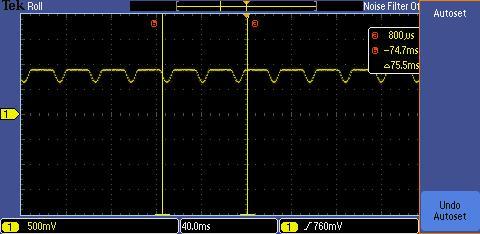
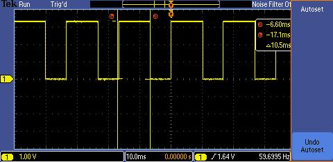
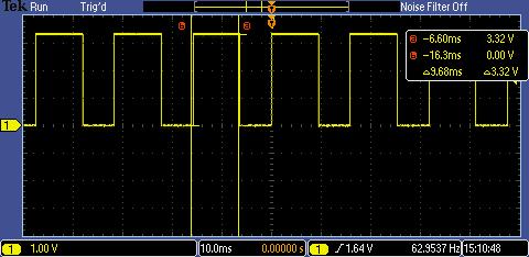
8 C) Software Design Our software design for this project consists of four major modules: an accelerometer handler, a button handler, a screen interface, and a sound/dac interface. Our main takes button inputs to start/stop playing notes or sound and to navigate menus, and then takes accelerometer input to alter the frequency of our DAC output to the speaker. This allows our instrument to play different notes based on accelerometer tilt. Menus and various measures of the note being played are displayed on the LCD. Our inputs, the accelerometer and buttons, are primarily handled through interrupts. The accelerometer uses a timer-based edge triggered interrupt to take the period of time that the accelerometer s PWM output is high. This allows our software to parse the varying PWM output that the accelerometer outputs, and then put that value through calculations to get a frequency value to output to the DAC. The buttons are edge-trigger interrupted with a timer-based wait to debounce them. The speakers are interfaced using SSI. Since the LM3S811 has only one SSI module, we manually operated an SSI transmission procedure to the DAC using GPIO output. The screen portion of our software uses the microcontroller s SSI module. D) Measurement Data DAC output testing based on accelerometer tilt: 5
9 6
10 Testing of accelerometer output based on tilt: 7

11 DAC Testing: DAC output value Voltage (V) Power consumption: The system runs at 3.3V and at a maximum of about 125 ma. This means that our system draws W at maximum. 8
12 E) Analysis and Discussion We can clearly see on the oscilloscope that the frequency of the waveform outputted to the DAC varies significantly based on tilt. The same goes for the accelerometer input. However, the accelerometer s PWM output would occasionally shake or jump in terms of the high period. Furthermore, we do not get the full 12-bit precision of our DAC, as evidenced by our DAC testing. We get about 11 bits of precision, likely from noise in our system. Because of these two factors, our sound output was not as clean as we had hoped, though it did vary recognizably with tilt. Our system draws significantly more current than we expected. Our predictions for our system s power consumption were based on a previous speaker-based project which drew at maximum 88 ma at 3.3V. Since our system sometimes drew 125 ma, our chosen voltage regulator was likely unable to handle the load of our system. Although the voltage regulator could regulate a 4.5 and 9 Volts to 3.3 Volts, it became extremely hot very quickly, and a nearby capacitor in the voltage regulator circuit popped. We likely should have used the LM2937 voltage regulator, which can handle up to 500 ma. However, due to time constraints we were unable to collect these parts in time for demonstration of our project, and had to do the majority of our testing using power from a DC power supply. During our soldering process, we also may have damaged our audio amplifier, or the noise in our system ruined its output. When testing the amplifier on an oscilloscope, it seemed to output random noise rather than the relatively clean DAC signal that we were outputting. We bypassed this problem by resoldering our speaker directly to the DAC. This made our sound output quieter, but significantly cleaned up our sound output. For future development, we might consider switching to a higher-power voltage regulator and switching out the surface-mount audio amplifier for a through-part component. Additionally, for the end user, we might try to reshape our PCB to make it more ergonomically accessible. 9
Final Report 26 April 2012
 EEL 4924 Electrical Engineering Design (Senior Design) Final Report 26 April 2012 Project Title: Keyboard Jockey Team Members: Name: Jeffrey Kaufman Name: Jacob Meacham Project Abstract Our project is
Rear Distance Detection with Ultrasonic Sensors Project Report
 Rear Distance Detection with Ultrasonic Sensors Project Report 11.29.2017 Group #6 Farnaz Behnia Kimia Zamiri Azar Osaze Shears ECE 511: Microprocessors Fall 2017 1 Table of Contents 1. Abstract 3 2. Motivation
Blobo Clone Angry Birds Toy Upgrade. Requirement and implementation specification and test plan
 Blobo Clone Angry Birds Toy Upgrade Requirement and implementation specification and test plan DOCUMENT INFORMATION Subject: Authors:, Keywords: Comments: Creation date: 10 December 2012 Revision date:
AUDIO AMPLIFIER PROJECT
 Intro to Electronics 110 - Audio Amplifier Project AUDIO AMPLIFIER PROJECT In this project, you will learn how to master a device by studying all the parts and building it with a partner. Our test subject:
Virtual Grand Piano. 1. Introduction Objective Background
 Virtual Grand Piano Team 64 - Zhi Lu, Jeongsub Lee and Hammad Khan ECE 445 Project Proposal - Spring 2018 TA: Mickey Zhang 1. Introduction 1.1. Objective Digital pianos currently available in the market
TEXAS INSTRUMENTS ANALOG UNIVERSITY PROGRAM DESIGN CONTEST MIXED SIGNAL TEST INTERFACE CHRISTOPHER EDMONDS, DANIEL KEESE, RICHARD PRZYBYLA SCHOOL OF
 TEXASINSTRUMENTSANALOGUNIVERSITYPROGRAMDESIGNCONTEST MIXED SIGNALTESTINTERFACE CHRISTOPHEREDMONDS,DANIELKEESE,RICHARDPRZYBYLA SCHOOLOFELECTRICALENGINEERINGANDCOMPUTERSCIENCE OREGONSTATEUNIVERSITY I. PROJECT
09/05/2014. Engaging electronics for the new D&T curriculum. Geoff Hampson Managing Director of Kitronik. Presentation overview
 Presentation overview Engaging electronics for the new D&T curriculum Geoff Hampson Managing Director of Kitronik What to include Free web resources Electronic project ideas Using programmable components
Design & Interface of Voice Module for Deaf and Dumb
 Design & Interface of Voice Module for Deaf and Dumb 1 Ch. Naveen, 2 J.Kavya Sree, 3 V. Raghu Charan, 4 CH. Manoj, 5 R. Kumara Swamy 1,2,3,4 Research Scholar, 5 Assistant Professor Dept. of E.C.E, NSRIT
EEL4914 Senior Final Design Report Beatbox Sensei
 Team Mic Jones EEL4914 Senior Final Design Report Beatbox Sensei Spring 2008 Submitted April 21, 2008 The project is inspired by a hip hop art called beatboxing. Beatboxing primarily involves the art of
EE445L Fall 2012 Quiz 2B Page 1 of 6
 EE445L Fall 2012 Quiz 2B Page 1 of 6 Jonathan W. Valvano First: Last: November 16, 2012, 10:00-10:50am. Open book, open notes, calculator (no laptops, phones, devices with screens larger than a TI-89 calculator,
ARM: Microcontroller Touch-switch Design & Test (Part 1)
") ARM: Microcontroller Touch-switch Design & Test (Part 1) 2 nd Year Electronics Lab IMPERIAL COLLEGE LONDON v2.00 Table of Contents Equipment... 2 Aims... 2 Objectives... 2 Recommended Timetable... 2 Introduction
ARM: Microcontroller Touch-switch Design & Test (Part 1) 2 nd Year Electronics Lab IMPERIAL COLLEGE LONDON v2.00 Table of Contents Equipment... 2 Aims... 2 Objectives... 2 Recommended Timetable... 2 Introduction
EMBEDDED SYSTEMS COURSE CURRICULUM
 On a Mission to Transform Talent EMBEDDED SYSTEMS COURSE CURRICULUM Table of Contents Module 1: Basic Electronics and PCB Software Overview (Duration: 1 Week)...2 Module 2: Embedded C Programming (Duration:
solutions for teaching and learning
 RKAmp3 Component List and Instructions PCB layout Constructed PCB Schematic RKAmp3 Stereo Amplifier Page 1 Description The RKAmp3 stereo amplifier PCB has been designed around the 2 x 7watt stereo amplifier
NEDSP1068-PCBA NEDSP1068-PCBA-MIC DSP
 bhi Ltd PO Box 318, Burgess Hill, RH15 9NR England. Tel: +44 (0)1444 870333 Fax: +44 (0)845 217 9936 info@bhi-ltd.com, www.bhi-ltd.com NEDSP1068-PCBA NEDSP1068-PCBA-MIC DSP Noise Cancelling Modules With
MP3 audio amplifier. Build Instructions. Issue 2.0
 MP3 audio amplifier Build Instructions Issue 2.0 Build Instructions Before you put any components in the board or pick up the soldering iron, just take a look at the Printed Circuit Board (PCB). The components
Comprehensive Design Review. Sync-In March 4, 2015
 Comprehensive Design Review Sync-In March 4, 2015 Advisor: Professor Gao 1 Sync-In Ajwad Alam, EE Amplifier/Power Joseph Bellve, EE ADC Levis Agaba, CSE DAC Carl Senecal, CSE Networking/Integration Advisor:
Group 10 Programmable Sensor Output Simulator Progress Report #2
 Department of Electrical Engineering University of Victoria ELEC 499 Design Project Group 10 Programmable Sensor Output Simulator Progress Report #2 March 5, 2005 Submitted by: Group No.: 10 Team: Exfour
Button Code Kit. Assembly Instructions and User Guide. Single Button Code Entry System
 Button Code Kit Single Button Code Entry System Assembly Instructions and User Guide Rev 1.0 December 2009 www.alan-parekh.com Copyright 2009 Alan Electronic Projects Inc. 1. Introduction... 4 1.1 Concept
DELUXE STEREO AMPLIFIER KIT
 ESSENTIAL INFORMATION BUILD INSTRUCTIONS CHECKING YOUR PCB & FAULT-FINDING MECHANICAL DETAILS HOW THE KIT WORKS CREATE YOUR OWN SPEAKER DOCK WITH THIS DELUXE STEREO AMPLIFIER KIT Version 2.0 Build Instructions
acsequencer Audio Sequencer unit partially controlled via a mobile application. Group 10:
 acsequencer Audio Sequencer unit partially controlled via a mobile application. Group 10: Brandon Marcoux (CpE) Giani Francis (Cpe) Miguel Chavez (Cpe) Alexis San Javier (Cpe) What is an Audio Sequencer?
VLSI AppNote: VSx053 Simple DSP Board
 : VSx053 Simple DSP Board Description This document describes the VS1053 / VS8053 Simple DPS Board and the VSx053 Simple DSP Host Board. Schematics, layouts and pinouts of both cards are included. The
Build Your Own Home Security System
 Build Your Own Home Security System Student Lab Guide Engineering Teaching Laboratory Name Date Lab Partner(s) NEW TERMS Electric Circuit: Electric circuits are paths for transmitting electric current,
Design Document. May Logging DC Wattmeter. Team Member: Advisor : Ailing Mei. Collin Christy. Andrew Kom. Client: Chongli Cai
 Design Document May13-06 Logging DC Wattmeter Team Member: Ailing Mei Andrew Kom Chongli Cai David Hoffman Advisor : Collin Christy Client: Garmin International Qiaoya Cui 0 Table of Contents EXECUTIVE
EE445L Fall 2018 Final EID: Page 1 of 7
 EE445L Fall 2018 Final EID: Page 1 of 7 Jonathan W. Valvano First: Last: This is the closed book section. Calculator is allowed (no laptops, phones, devices with wireless communication). You must put your
Cookie User Manual. For NuMicro Edition 1.0. Rev. 1.0 Release: forum.coocox.org.
 Cookie User Manual For NuMicro Edition 1.0 Rev. 1.0 Release: 2012-08-09 Website: Forum: Techinal: Market: www.coocox.org forum.coocox.org master@coocox.com market@coocox.com 1 Introduction Cookie is an
Embedded Piano Interfaced with LCD
 Embedded Piano Interfaced with LCD Akshita Vinod Nichani U.G. Student, Electronics and Telecommunication Department, DJSCE Shruti Tushar Pistolwala U.G. Student, Electronics and Telecommunication Department,
Application Report. 1 Hardware Description. John Fahrenbruch... MSP430 Applications
 Application Report SLAA309 June 2006 Low-Power Tilt Sensor Using the MSP430F2012 John Fahrenbruch... MSP430 Applications ABSTRACT The MSP430 family of low-power microcontrollers are ideal for low-power
TINA-TI Simulation Software. Application Note
 TINA-TI Simulation Software Application Note Phil Jaworski Design Team 6 11/16/2012 Abstract TINA-TI is a circuit design and simulation tool created by both Texas Instruments and DesignSoft that has helped
Homework 6: Printed Circuit Board Layout Design Narrative Due: Friday, February 27, at NOON
 Homework 6: Printed Circuit Board Layout Design Narrative Due: Friday, February 27, at NOON Team Code Name: _Magic Wand Group No. 5 Team Member Completing This Homework: Michelle Zhang E-mail Address of
Olfaction Satisfaction Week #10 April 5, 2006 Senior Design Team 8
 Olfaction Satisfaction Week #10 April 5, 2006 Senior Design Team 8 Work Completed The first task for Emily this week was to finish debugging the circuit. The sound chip problem was finally figured out.
INSTRUCTION MANUAL A141 High Level Audible Warning System
 24V DC (18V to 30V DC range) 115 or 230VAC (90V to 264V AC range) Operating Temp: -20 to +55 C IP Rating: IP65 Marking: 3) Installation Requirements 1) Introduction The A141 high level audible warning
Homework 6: Printed Circuit Board Layout Design Narrative
 Homework 6: Printed Circuit Board Layout Design Narrative Team Code Name: Home Kinection Group No. 1 Team Member Completing This Homework: Stephen Larew E-mail Address of Team Member: sglarew @ purdue.edu
Preliminary Design Report
 EEL 4924 Electrical Engineering Design (Senior Design) Preliminary Design Report 31 Jan 2012 Project Title: Keyboard Jockey Team Members: Name: Jeffrey Kaufman Name: Jacob Meacham Project Abstract Our
PIC DESIGN (version 1) 2/11/2009
 2/11/2009") PIC DESIGN (version 1) 2/11/2009 The decision to design and construct a custom microcontroller was dictated by both practical and educational reasons. Although microcontroller development boards are readily
PIC DESIGN (version 1) 2/11/2009 The decision to design and construct a custom microcontroller was dictated by both practical and educational reasons. Although microcontroller development boards are readily
ECG (EKG) Primer Jingxi Zhang ABSTRACT
 Primer Jingxi Zhang ABSTRACT") ECG (EKG) Primer Jingxi Zhang ABSTRACT This project is for detecting human ECG (Electrocardiogram, or EKG). A tiny amplifier is embedded (
ECG (EKG) Primer Jingxi Zhang ABSTRACT This project is for detecting human ECG (Electrocardiogram, or EKG). A tiny amplifier is embedded (
STAGE INTERCOM KIT 1.1 SPECIFICATION. General: The lower section is a small power amplifier designed to drive headphones or a small 8ohm speaker.
 STAGE INTERCOM KIT Version 2.1.1 - March 2018 - EduTek Ltd 1.0 DESCRIPTION This intercom module comprises of two separate circuits sharing the same supply. The upper section is a pre-amplifier designed
GROUP 14: ESSENCE OF MUSIC. Joshua Garber EE Baron Dolletski-Lazar CpE Nelson Tan - CpE
 GROUP 14: ESSENCE OF MUSIC Joshua Garber EE Baron Dolletski-Lazar CpE Nelson Tan - CpE Motivation Gain experience working with Audio Signals Implementing multiple systems to operate simultaneously (Audio
Accelerometer Mouse: Hardware Description
 Accelerometer Mouse: Hardware Description Chris Wittmier ET474 Professor Todd Morton Western Washington University 04/19/2005 Introduction The accelerometer mouse is a wireless USB mouse that operates
Exclusive 2.5 GHz Frequency Counter
 Exclusive 2.5 GHz Frequency Counter with blue 2 x 16 LCD display This manual will guide you how to assemble, test and tune this frequency counter KIT. Features: Frequency range from 5 MHz to 2.5GHz Factory
Preliminary Design Report
 Preliminary Design Report EEL4924-Electrical Engineering Design 2 University of Florida 25 January 2012 Team Members: Ryan Griffin & Brie Colon Project Abstract: Our project consists of designing an electronic
8051 Intermidiate Development Board. Product Manual. Contents. 1) Overview 2) Features 3) Using the board 4) Troubleshooting and getting help
 Overview 2) Features 3) Using the board 4) Troubleshooting and getting help") 8051 Intermidiate Development Board Product Manual Contents 1) Overview 2) Features 3) Using the board 4) Troubleshooting and getting help 1. Overview 2. Features The board is built on a high quality FR-4(1.6
8051 Intermidiate Development Board Product Manual Contents 1) Overview 2) Features 3) Using the board 4) Troubleshooting and getting help 1. Overview 2. Features The board is built on a high quality FR-4(1.6
Lost Item Pager. Project Description. Russ Kinley
 Lost Item Pager Project Description Russ Kinley Introduction The lost item pager will have a base unit that is stationary, consisting of a few page buttons and a digital display. Each of the buttons will
HARDWARE OPERATIONS MANUAL
 HARDWARE OPERATIONS MANUAL Table of Contents INTRODUCTION... 2 SECTION 1: HARDWARE COMPONENT ASSEMBLIES... 2 MECHANICAL HARDWARE AND CASE... 2 PCB ASSEMBLY... 4 ISD RECORDING CIRCUIT... 5 BREADBOARD ASSEMBLY...
AVR Intermediate Development Board. Product Manual. Contents. 1) Overview 2) Features 3) Using the board 4) Troubleshooting and getting help
 Overview 2) Features 3) Using the board 4) Troubleshooting and getting help") AVR Intermediate Development Board Product Manual Contents 1) Overview 2) Features 3) Using the board 4) Troubleshooting and getting help 1. Overview 2. Features The board is built on a high quality FR-4(1.6
AVR Intermediate Development Board Product Manual Contents 1) Overview 2) Features 3) Using the board 4) Troubleshooting and getting help 1. Overview 2. Features The board is built on a high quality FR-4(1.6
Goal: We want to build an autonomous vehicle (robot)
") Goal: We want to build an autonomous vehicle (robot) This means it will have to think for itself, its going to need a brain Our robot s brain will be a tiny computer called a microcontroller Specifically
Goal: We want to build an autonomous vehicle (robot) This means it will have to think for itself, its going to need a brain Our robot s brain will be a tiny computer called a microcontroller Specifically
Freescale Semiconductor Inc. Microcontroller Solutions Group. FRDM-KL46Z User s Manual FRDM-KL46Z-UM Rev. 1.0
 Freescale Semiconductor Inc. Microcontroller Solutions Group FRDM-KL46Z User s Manual FRDM-KL46Z-UM Rev. 1.0 Table of Contents 1 FRDM-KL46Z Overview... 3 2 References documents... 3 3 Getting started...
Propeller Board of Education (#32900)
") Web Site: www.parallax.com Forums: forums.parallax.com Sales: sales@parallax.com Technical: support@parallax.com Office: (916) 624-8333 Fax: (916) 624-8003 Sales: (888) 512-1024 Tech Support: (888) 997-8267
Web Site: www.parallax.com Forums: forums.parallax.com Sales: sales@parallax.com Technical: support@parallax.com Office: (916) 624-8333 Fax: (916) 624-8003 Sales: (888) 512-1024 Tech Support: (888) 997-8267
Embedded Systems Laboratory
 Embedded Systems Laboratory Using ARM Cortex M4 From the Basics to Applications Internet of Things Why M4? Market share Complexity Parallelism Verification 1 Outline 1. Objectives 2. Approach 5 Takeaways
Real-Time Parking Information Solution. Team 9. Them Le - EE Danny Russell - CpE Carlos Pereda -
 Real-Time Parking Information Solution Team 9 Them Le - EE Danny Russell - CpE Carlos Pereda - Division of Tasks Them Le (EE) Power System, Hardware, Eagle CAD drawings. Carlos Pereda (CpE) Database, Back-end
Open Sesame. Grant Apodaca Jeffrey Bolin Eric Taba Richie Agpaoa Evin Sellin
 Open Sesame Grant Apodaca Jeffrey Bolin Eric Taba Richie Agpaoa Evin Sellin 1 Description Open Sesame is a portable, affordable, compact and easyto-use door security accessory, that can unlock your door
Stellaris LM3S3748 Evaluation Kit README FIRST
 Stellaris LM3S3748 Evaluation Kit README FIRST The Stellaris LM3S3748 Evaluation Kit provides a low-cost way to start designing applications with Stellaris microcontrollers on a compact and versatile evaluation
Pacific Antenna Two Tone Generator
 Pacific Antenna Two Tone Generator Description Our Two Tone Generator kit provides two non-harmonic, sine wave signals for testing audio circuits Outputs of approximately 700Hz and 1900Hz and the combination
Homework 3: Design Constraint Analysis and Component Selection Rationale
 Homework 3: Design Constraint Analysis and Component Selection Rationale Team Code Name: 2D-MPR Group No. 12 Team Member Completing This Homework: James Phillips E-mail Address of Team Member: jephilli@
MP3 Boombox ECE 511 PROJECT GROUP 11 12/03/2013 CARLOS R ARAUJO BRIAN D JARVIS SHAWN WILKINSON DIVYA CHINTHALAPURI LEEGIA S JACOB
 MP3 Boombox ECE 511 PROJECT GROUP 11 12/03/2013 CARLOS R ARAUJO BRIAN D JARVIS SHAWN WILKINSON DIVYA CHINTHALAPURI LEEGIA S JACOB Abstract For this project, the motivation was to create a product which
Arduino Uno. Arduino Uno R3 Front. Arduino Uno R2 Front
 Arduino Uno Arduino Uno R3 Front Arduino Uno R2 Front Arduino Uno SMD Arduino Uno R3 Back Arduino Uno Front Arduino Uno Back Overview The Arduino Uno is a microcontroller board based on the ATmega328 (datasheet).
Homework 5: Circuit Design and Theory of Operation Due: Friday, February 24, at NOON
 Homework 5: Circuit Design and Theory of Operation Due: Friday, February 24, at NOON Team Code Name: Motion Tracking Laser Platform Group No.: 9 Team Member Completing This Homework: David Kristof NOTE:
ASV 2008 Son of a Boatname. Group 1 Michael Podel Gor Beglaryan Kiran Bernard Christina Sylvia
 ASV 2008 Son of a Boatname Group 1 Michael Podel Gor Beglaryan Kiran Bernard Christina Sylvia ASV 2009 SS Boatname ASV 2010 Boatname the Brave Autonomous Surface Vehicle Robotics Club at UCF AUVSI and
ECE 189A Senior Capstone December 16, 2014 Team Leader: Will Miller Charles Crain, Isaac Flores, Brian Phan, Sarah Pilkington
 ECE 189A Senior Capstone December 16, 2014 Team Leader: Will Miller Charles Crain, Isaac Flores, Brian Phan, Sarah Pilkington Agenda Project Overview Parts Power Distribution Schematic and Bill of Materials
Introduction to MATLABs Data Acquisition Toolbox, the USB DAQ, and accelerometers
 Introduction to MATLABs Data Acquisition Toolbox, the USB DAQ, and accelerometers This week we will start to learn the software that we will use through the course, MATLAB s Data Acquisition Toolbox. This
Design Requirements: Workstation Test System
 Design Requirements: Workstation Test System ECE 4890 - Senior Sear April 16, 2010 By: Andrew Dunn & Holly Peterson Faculty Advisor: Bob Kressin Sponsor: Tim Figge, Agilent Table of Contents Overview...
Major Components Parts Power System Power supplies Ground Reset System Clocks and Timing Inputs and Outputs
 Troubleshooting and Debugging Pieces Hardware Software Drawings and source code Hardware Major Components Parts Power System Power supplies Ground Reset System Clocks and Timing Inputs and Outputs Parts
ARDUINO MICRO WITHOUT HEADERS Code: A000093
 ARDUINO MICRO WITHOUT HEADERS Code: A000093 Arduino Micro is the smallest board of the family, easy to integrate it in everyday objects to make them interactive. The Micro is based on the ATmega32U4 microcontroller
AC : DESIGN OF DATA ACQUISITION SYSTEM FOR COMPUTER ENGINEERING EDUCATION
 AC 2007-3083: DESIGN OF DATA ACQUISITION SYSTEM FOR COMPUTER ENGINEERING EDUCATION Yoon Kim, Virginia State University YOON G. KIM is an Assistant Professor of Computer Engineering in the Department of
Figure 1. A test controller communicates with User I/O, the DUT, a DMM, and a PC (for program development).
.") Build a microcontroller-based functional tester Save money by embedding test capabilities into fixtures, enclosures, or larger systems. Overton Claborne, Overton Instruments A typical PC-based test system
Build a microcontroller-based functional tester Save money by embedding test capabilities into fixtures, enclosures, or larger systems. Overton Claborne, Overton Instruments A typical PC-based test system
Wireless OBD II CAN Bus Embedded System Design
 Wireless OBD II CAN Bus Embedded System Design Carmen Bovalino January 2014 Table of Contents Objective... 1 Background... 1 Description of Proposal... 2 System Operation... 3 System Requirements... 3
Variable Power Supply Digital Control Circuit Diagram Using Lm317
 Variable Power Supply Digital Control Circuit Diagram Using Lm317 DIGITAL POWER SUPPLY USING LM317 A Major Project Report Submitted partial fulfillment of the requirement for the award of the Degree of
EE445L Fall 2014 Final Version A Page 1 of 7
 EE445L Fall 2014 Final Version A Page 1 of 7 Jonathan W. Valvano First: Last: This is the closed book section. You must put your answers in the boxes. When you are done, you turn in the closed-book part
LCD Prototype Circuit on Solderless Breadboard. 840 Pin Solderless Breadboard (http://www.digikey.com/ # ND)
") Solderless Breadboard Tutorial Cornerstone Electronics Technology and Robotics I Week 3 Solderless Breadboards: o Solderless breadboards are commonly used in experimentation or to make a prototype of a
Solderless Breadboard Tutorial Cornerstone Electronics Technology and Robotics I Week 3 Solderless Breadboards: o Solderless breadboards are commonly used in experimentation or to make a prototype of a
EECS 211 CAD Tutorial. 1. Introduction
 EECS 211 CAD Tutorial 1. Introduction This tutorial has been devised to run through all the steps involved in the design and simulation of an audio tone control amplifier using the Mentor Graphics CAD
Homework 6: Printed Circuit Board Layout Design Narrative
 Homework 6: Printed Circuit Board Layout Design Narrative Team Code Name: Treasure Chess Group No. 2 Team Member Completing This Homework: Sidharth Malik E-mail Address of Team Member: malik @ purdue.edu
Clicker 2 for Kinetis
 Page 1 of 6 Clicker 2 for Kinetis From MikroElektonika Documentation clicker 2 for Kinetis is a compact dev. kit with two mikrobus sockets for click board connectivity. You can use it to quickly build
[Note: Power adapter is not included in the kits. Users need to prepare a 9 12 V ( >300mA capacity ) DC power supply]
![[Note: Power adapter is not included in the kits. Users need to prepare a 9 12 V ( >300mA capacity ) DC power supply]](/thumbs/76/74094055.jpg "[Note: Power adapter is not included in the kits. Users need to prepare a 9 12 V ( >300mA capacity ) DC power supply]") 062 LCD Oscilloscope Assembly Notes Applicable Models: 06203KP, 06204KP DN062-18v02 Important Notes 1. Some components shown in the schematic and PCB layout are for options or adjustments. They do not
062 LCD Oscilloscope Assembly Notes Applicable Models: 06203KP, 06204KP DN062-18v02 Important Notes 1. Some components shown in the schematic and PCB layout are for options or adjustments. They do not
PicoBoo AC. OPERATING MANUAL V1.1 (Sep 8, 2011) 6 Oakside Court Barrie, Ontario L4N 5V5 Tel: or
 6 Oakside Court Barrie, Ontario L4N 5V5 Tel: or") PicoBoo AC OPERATING MANUAL V1.1 (Sep 8, 2011) 6 Oakside Court Barrie, Ontario L4N 5V5 Tel: 1-877-815-5744 or 905-803-9274 www.frightideas.com Getting Familiar with your PicoBoo PicoBoo AC Operating Manual
PicoBoo AC OPERATING MANUAL V1.1 (Sep 8, 2011) 6 Oakside Court Barrie, Ontario L4N 5V5 Tel: 1-877-815-5744 or 905-803-9274 www.frightideas.com Getting Familiar with your PicoBoo PicoBoo AC Operating Manual
Overview of Microcontroller and Embedded Systems
 UNIT-III Overview of Microcontroller and Embedded Systems Embedded Hardware and Various Building Blocks: The basic hardware components of an embedded system shown in a block diagram in below figure. These
Home Security System with Remote Home Automation Control
 Home Security System with Remote Home Automation Control Justin Klumpp Senior Project Hardware Description Western Washington University April 24 2005 Professor Todd Morton Introduction: This document
Smart Lights. By: Group 2 Ryad Hafeez Kevin Patel Anthony Chand James Harrison
 Smart Lights By: Group 2 Ryad Hafeez Kevin Patel Anthony Chand James Harrison Project Overview Using a Android application, a user can control their lights. A user will be able to play a song and have
CSE 466 Exam 1 Winter, 2010
 This take-home exam has 100 points and is due at the beginning of class on Friday, Feb. 13. (!!!) Please submit printed output if possible. Otherwise, write legibly. Both the Word document and the PDF
Transcendent Frequency Counter
 Transcendent Frequency Counter with blue 2 x 16 LCD display This manual will guide you how to assemble, test and operate this frequency counter KIT. Features: The transcendent counter has two input channels
TPA4861 Audio Power Amplifier Evaluation Module DATA MANUAL: SLOU004
 TPA4861 Audio Power Amplifier Evaluation Module DATA MANUAL: SLOU004 Date: July 1997 IMPORTANT NOTICE Texas Instruments and its subsidiaries (TI) reserve the right to make changes to their products or
Blobo Clone Angry Birds Toy Upgrade. Schedule of the project and log of work done
 Blobo Clone Angry Birds Toy Upgrade Schedule of the project and log of work done DOCUMENT INFORMATION Subject: Authors:, Keywords: Comments: Creation date: 10 December 2012 Revision date: 02/21/13 Print
TI Designs: TIDA Power Supply Reference Design for Automotive Microcontroller in Gateway and Body Control Module
 TI Designs: TIDA-1412 Power Supply Reference Design for Automotive Microcontroller in Gateway Description This discrete power supply reference design demonstrates a complete power solution for the Freescale
iphone Noise Filtration Hardware
 Iowa State University ECPE Senior Design iphone Noise Filtration Hardware Design Plan Michael Bullis Andrew Mungons Yang Yang 2011 Client Rockwell Collins Faculty Advisor Dr. Zhengdao Wang G r o u p M
Bill of Materials: Handheld Game System PART NO
 Handheld Game System PART NO. 2245108 Build your own Handheld Game System with graphics and sound! This game kit includes a custom designed circuit board along with custom built tools and programming to
SpokePOV. Bicycle Wheel Persistence of Vision Device. Jared Myren Patrick Hyland
 SpokePOV Bicycle Wheel Persistence of Vision Device Jared Myren jmyren@calpoly.edu Patrick Hyland phyland@calpoly.edu Materials Engineering Department, Cal Poly SLO Spring Quarter 2011 Abstract The objective
utinkerer v1.1 User s Manual
 utinkerer v1.1 User s Manual Last Updated January 6, 2013 2 WARNING READ BEFORE USE!!! 1) DO NOT OVERLOAD OR SHORT POWER RAILS. out of the Box is not responsible for any damage to personal property through
Outline. A Computerbased. Instrument for Measuring Distance for a Soccer Free- Kick 10/16/2016. Andy Vongphachanh Matthew Weeks
 A Computerbased Instrument for Measuring Distance for a Soccer Free- Kick Andy Vongphachanh Matthew Weeks Outline Introduction Scope Physical Diagram System Architecture Hardware Software Construction
High Power (15W + 15W) Stereo Amplifier
 Stereo Amplifier") High Power (15W + 15W) Stereo Amplifier Build Instructions Issue 1.0 Build Instructions Before you put any components in the board or pick up the soldering iron, just take a look at the Printed Circuit
High Power (15W + 15W) Stereo Amplifier Build Instructions Issue 1.0 Build Instructions Before you put any components in the board or pick up the soldering iron, just take a look at the Printed Circuit
MAXREFDES108#: NON-ISOLATED 12V/1A POE POWERED DEVICE POWER SUPPLY
 System Board 6289 MAXREFDES108#: NON-ISOLATED 12V/1A POE POWERED DEVICE POWER SUPPLY To meet the increasing demands for non-isolated Power over Ethernet (PoE) power solutions, Maxim has developed innovative,
ACU6. Technical Reference Manual. Specifications Interfacing Dimensions. Document topics. ANSARI Controller Unit Type 6 technical reference manual
 ACU6 Technical Reference Manual ANSARI Controller Unit Type 6 technical reference manual Document topics Specifications Interfacing Dimensions Document Version: 1.03 13. January 2013 By ANSARI GmbH Friedrich-Ebert-Damm
Saber Hand Wind Audio Player User Guide
 Saber Hand Wind Audio Player User Guide February 2014 globalrecordings.net/saber Table of Contents 1.Introduction...3 1.1 Before You Start...3 1.2 Other information available...3 1.3 Contact Details...3
2005 Pioneer Home Audio Seminar VSX49TX
 2005 Pioneer Home Audio Seminar VSX49TX Pioneer Electronic Service, Inc. 2005 Introduction Why the VSX49TX? The VSX49TX is not current product, however it tends to be the most difficult to repair! What
solutions for teaching and learning
 Circuit Construction Op-Amp Comparator Project The circuit diagram on the right is the circuit for your project, it is called an op-amp comparator circuit, it is called a comparator circuit as it compares
Input/Output Modes Chapter 8
 Input/Output Modes Chapter 8 Microcomputers can communicate with a variety of I/O devices This information can be either data or control Data is usually encoded in numeric or alphanumeric forms such as
ARDUINO YÚN Code: A000008
 ARDUINO YÚN Code: A000008 Arduino YÚN is the perfect board to use when designing connected devices and, more in general, Internet of Things projects. It combines the power of Linux with the ease of use
LPC2148 DEV BOARD. User Manual.
 LPC2148 DEV BOARD User Manual www.coineltech.com www.coineltech.com Designed by CoiNel Technology Solutions LLP No-816, 2 nd Floor, 4 th B Cross, 9 th A Main, RPC Layout, Vijaynagar, Bangalore-560040 State:
November 2000 Mixed-Signal Products SLOU086
 User s Guide November 2000 Mixed-Signal Products SLOU086 IMPORTANT NOTICE Texas Instruments and its subsidiaries (TI) reserve the right to make changes to their products or to discontinue any product or
BLUETOOTH AMPLIFIER KIT
 PRODUCT INFORMATION BUILD INSTRUCTIONS CHECKING YOUR PCB & FAULT-FINDING MECHANICAL DETAILS HOW THE KIT WORKS CREATE YOUR OWN WIRELESS SPEAKER WITH THIS BLUETOOTH AMPLIFIER KIT Version 1.2 Index of Sheets
Test Methods for DC/DC Power Modules
 Test Methods for DC/DC Power Modules Design Note 027 Flex Power Modules Precautions Abstract A user may have the desire to verify or characterize the performance of DC/DC power modules outside the system
EZ-Bv4 Datasheet v0.7
 EZ-Bv4 Datasheet v0.7 Table of Contents Introduction... 2 Electrical Characteristics... 3 Regulated and Unregulated Power Pins... 4 Low Battery Warning... 4 Hardware Features Main CPU... 5 Fuse Protection...
// middle priority ISR Status.flag = 1; Status.y = 6;
 EE445L Spring 2018 Quiz 1A Page 1 of 6 Jonathan W. Valvano First: Last: March 1, 2018, 3:30pm-4:45pm. This is a closed book exam, with one 8.5 by 11-inch crib sheet. You have 75 minutes, so please allocate