MTP INSTRUCTION MANUAL
|
|
|
- Gary Garrison
- 5 years ago
- Views:
Transcription

1 MTP INSTRUCTION MANUAL Wireless Electricity Monitor Model MTP-3100 MTP Instruments Inc.
2 Table of Content 1. Introduction Page 1 2. Safety and Maintenance Information Page 1 3. Features / Specifications Page 2 4. Package Content Page 2 5. Product Layout Page 3 6. Display Screen Information and Clearing Data Page 4 7. Installation / Set-up Page Installation of Sensor Clamp Page Linking the Transmitter with the Display Page Display Screen Set-up Instructions Page 10 8 Operation Page 15 9 Frequently Asked Questions Page 21
3 1. Introduction Congratulations on the purchase of this smart wireless electricity monitor, Model MTP This product was designed to monitor and better manage electricity consumption. This guide is aimed at helping you in the set-up of the wireless monitoring system. Careful use of this device will provide years of reliable service Please note this manual will refer to the below devices in the following manner: Receiver = Monitor (M) Sender = Transmitter (T) 2. Safety and Maintenance Information Before installation, please pay attention to the following information: Please read all instructions before you use the monitoring system. Please shake the display unit and the power transmitter first, before installation. Do not use if you hear any sound from inside of the parts and communicate with your authorized distributor for replacement. Do not allow children or people unfamiliar with these instructions to use your monitoring system. Keep the monitor, transmitter and sensor clamp away from sources of heat, water or any other liquid. Place the monitor, transmitter and sensor clamp where children can not touch or pull. Do not try to disassemble or modify any parts of the monitoring system. In case of problem, please consult your representative. Do not use the monitoring system if you find your electric wire in abnormal condition, such as loose wire, exposed copper wire, burnt mark on wire insulation layer, holes on wire layer or damage on electric meter. In case of such abnormalities, please consult a professional electrician immediately. Periodically check all wires and components to ensure there is no damage. Use a dry cloth to clean. Do not use solvent, abrasive cleaners or water. For installation, it is recommended that you contact a qualified electrician. In some countries, the electrical panel can only be accessed by qualified electricians. Contact MTP Instruments Inc. to find out if it s mandatory in the country you live in. 1
4 3. Features / Specifications 1. Model Name / Number: MTP Frequency: 433MHz 3. Transmission Time: 10s, 15s, 20s (settable) 4. Transmission Range: 70m 5. Voltage Range: 90V to 600V 6. Measuring Current: 100A (max) 7. Accuracy: 0.15A-1A ± 30% / 1A-100A ± 7% 8. Tariff Periods: Three (3) periods 9. Temperature: Celsius and Fahrenheit 10. History: Instant, Daily, Weekly, Monthly 11. Display: Instant Energy (kw), Energy Consumed (kwh), Dollar Value ($), Pollution (kg. CO2) Backlight: See page 17 Warranty: One (1) year 12. Certifications: IC, FCC, ETL 13. Country of Origin: China 14. Size of Monitor: 145 x 109 x 60mm 15. Size of Transmitter: 92 x 72 x 43mm 16. Weight of Monitor: 300g with "AA" batteries 17. Weight of Transmitter: 320g with 2 type "C" batteries 18. Diameter of Clamps: 18mm 19. Operating Temperature: 0 C to 50 C 20. Storage Temperature: -10 C to 50 C 4. Package Content If any of the parts listed below are missing, please contact your authorized distributor immediately. 1 x Display Unit (Monitor) 1 x Wireless Transmitter (includes x 2 type "C" batteries) 2 x Sensor Clamps w/ 18mm diameter 1 x Data Cable RJ45-USB 3m 1 x Power Adapter 1 x User Manual in English and French 1 x Mini CD for Software Note: Batteries for Monitor not included. Monitor requires (x03) AA batteries. It is recommended to use Lithium batteries. 2

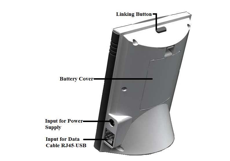
5 5. Product Layout 3
, the LCD screen will automatically return to the default screen.")
6 6. Display Screen Information and Clearing Data Soon after successfully pairing the monitor and transmitter, the LCD screen will automatically return to the default display. Furthermore, when there is no button operation (for a period of time), the LCD screen will automatically return to the default screen. Below is an example of the default LCD screen. 4

. At this point, the data contained in the memory should be cleared.")
7 Resetting and Data Clearance When the default screen is displayed, simultaneously press and hold down the SET/MODE and HISTORY keys. The full LCD screen will appear for 10 seconds (See Fig. 1). The red LED light will then flash. At this point, release SET/MODE and HISTORY keys. At this point, release the SET/MODE and HISTORY keys. The LED light will go on and the programming version will be displayed on the LCD screen for approximately 3 seconds (See Fig. 2). The LED light will then turn off and the LCD screen will return to the default display with no signal condition (See Fig. 3). At this point, the data contained in the memory should be cleared. Note: Resetting the memory will display the factory settings (Date: 01/01/2011 and Time: 00:00). Fig. 1 Fig. 2 Fig Installation / Set-up IMPORTANT: It is recommended to contact a qualified electrician for the installation of this product. 7.1 Installation of Sensor Clamp Clip the sensor clamp around the "Live Wire" of the electricity panel. The live wire is usually located behind a metal cover. (Please contact a qualified electrician). Regarding three phase supply, a third sensor clamp is needed (sold separately). Please contact MTP Instruments for additional sensors. Installing the sensor clamp to the live wire. First, push the release cap. Second, place it on the correct live wire. Third, close the sensor clamp. Finally, ensure that the sensor clamp(s) is/are plugged into the transmitter. 5
8 Note: It is normal when installing the (detachable) sensor clamp on a live wire, that the sensor emits a vibrating sound when it is not plugged into the transmitter. Once the sensor is connected to the live wire and plugged to the transmitter, the vibrating sound will cease. Note: Detachable sensor clamp can be plugged into any of the two inputs of the transmitter, when making connection. To ensure that the connection of the sensor clamp is successful, verify if the sensor clamp symbol is displayed on the top left corner of the monitor (eg. if two sensors are connected, the monitor should display two sensor clamp symbols). 6


.")
9 IMPORTANT NOTICE: Please contact a qualified electrician to carry out the installation. We will not be held responsible for damage as a result of a wrong connection. Please note that monitor displays the Apparent Power (VA) and not the Active Power (watts). Installation on standard 200A panel Unscrew the four corners to remove the electrical panel protection cover. Fit the two enclosed 100A clip-on sensors (sensors are suitable for use with wire diameters up to 18mm) to the live feed cables of the electrical panel. Insert each jack on the end of the white wire into any of the input sockets of the transmitter. The clip-on sensor acts as a current sensor and relays the current being drawn into the home to the transmitter. From there, it is sent wirelessly to the monitor display unit. Link the transmitter to the monitor. Please refer to the instructions on page 9 of the instruction manual. (Ensure three AA batteries are inserted in the transmitter and the display unit). Transmitter Please refer to pages 10 to 15 for set-up of the monitor. IMPORTANT : Select 120V as reference voltage Information is displayed on the monitor. Please refer to pages 15 to 20 of this instruction manual. Please note that monitor displays the Apparent Power (VA) and not the Active Power (watts). 7
10 Installation on a 3 phase 3 wire system L1 Install the two enclosed sensors (100A), as indicated on diagram 1 (phase 1 and phase 3). Connect the two heavy duty sensors to the transmitter. Insert each jack on the end of the white wire into any of the input sockets of the transmitter. L2 The clip-on sensor acts as a current sensor and relays the current being drawn into the home to the transmitter. Link the transmitter to the monitor. Please refer to the instructions on page 9 of the instruction manual. (Ensure three AA batteries are inserted in the transmitter and the display unit). Diagram 1 L3 Please refer to pages 10 to 15 for monitor set-up. IMPORTANT: The reference voltage is equal to the voltage between phase 1 and phase 3, divided by (Ex. If voltage between phase 1 and 3 is 600V, the reference voltage will therefore be 600 / = 347V). Please refer to instructions of pages 15 to 20 for display of information on the monitor. Installation on a 3 phase 4 wire system L1 Install three sensors (100A), as indicated on diagram 2. Connect the three heavy duty sensors to the transmitter. Insert each jack on the end of the white wire into any of the input sockets of the transmitter. Neutral The clip-on sensor acts as a current sensor and relays the current being drawn into the home to the transmitter. Link the transmitter to the monitor. Please refer to the instructions on page 9 of the instruction manual. (Ensure three AA batteries are inserted in the transmitter and the display unit). Diagram 2 L2 L3 Please refer to pages 10 to 15 for monitor set-up. IMPORTANT: The reference voltage is equal to the voltage of NEUTRAL-PHASE (ex: 600V NEUTRAL-PHASE system = 347V). Please refer to pages 15 to 20 for display of information on the monitor. IMPORTANT NOTICE: Please contact a qualified electrician to carry out the installation. We will not be held responsible for damage as a result of a wrong connection. Please note that monitor displays the Apparent Power (VA) and not the Active Power (watts).
11 7.2 Linking the Transmitter with the Display 1. Remove the clear plastic tab located on the back of the transmitter (marked: REMOVE BEFORE USING). Removing the plastic tab will power the transmitter and the light on the transmitter will begin to flash. Note : During the linking process, keep the transmitter and monitor as close as possible to each other. 2. On the monitor, press and hold down the Linking button (approx. 5 seconds) until the red light flashes, then release the button. When in signal searching mode, an antenna icon will flash at the top corner of the screen while simultaneously a progress histogram will appear on the screen (See Fig. 4, 5, 6). 3. While the monitor is in signal searching mode Press and hold down the button on the front of the transmitter for 15 seconds, then release it. Once released, a red light on the transmitter will begin flickering non-stop, meaning the transmitter is in signal searching mode. Note : When the transmitter is in signal searching mode, the LED will flash rapidly and only in RED. This should not be confused with the signal frequency setting which can be programmed every 10, 15, or 20 seconds. Depending which preference is selected, the frequency of the LED flash and color will vary ( See : Signal Frequency Setting (Transmitter) on page 21). Fig. 4 Fig. 5 Fig. 6 Linking Successful Once the monitor successfully receives the signal from the transmitter, the LCD screen will return automatically to the default display (See Fig. 7). At this point, the antenna icon will appear at the top left corner of the LCD screen. Linking Failed In the situation the monitor fails to acquire a signal from the transmitter (in one minute), the LCD screen will return automatically to the default display and no antenna icon will be displayed. 9
.")
12 Fig. 7 Fig. 8 Fig Display Screen Set-up Instructions While the default screen is displayed (See Fig. 7), press and hold down the SET/MODE key for 3 seconds. Then the red LED light flashes twice, release the SET/MODE key. At this point, the monitor will enter in Setting Mode (See Fig. 8). While in Setting Mode, you may scroll UP or DOWN and select the interface that needs to be set. When scrolling UP or DOWN, the following choices will be flashing: (Voltage, Kr (Currency), Tariff, Kg CO 2, Max.P (Maximum Power Alarm), Clock, 01/01/2011 (Date), Temp. (Temperature Unit and "boff" (Buzzer). To select the desired interface, press the SET/MODE key. At any time during the set-up process, you may save and exit the Setting Mode and return to the default display by pressing the HISTORY button. Voltage Setting The adjustable range for the voltage is V. The default voltage setting when leaving the factory is 120V. When the VOLTAGE symbol flashes, press the SET/MODE key to enter the voltage setting interface (See Fig. 9). The first digit 1 will start flashing meaning that the first value (0-6) can be selected by pressing the UP or DOWN key. To confirm the first digit, press the SET/MODE key. Once the first digit is set, the second digit will start flashing. Similarly, press the UP or DOWN key to select the desired value for the second digit (0-9). To confirm the second value, press the SET/MODE key. The third digit will begin to flash and the last digit can be selected (0-9) using the UP or DOWN key. Press the SET/MODE key to confirm and return to the Setting Mode. 10
13 Currency Setting While in Setting Mode, use the UP or DOWN key to scroll through the options and select the flashing Kr symbol. To access the currency interface, press the SET/MODE key (See Fig. 10). Press the UP or DOWN key to select the desired currency and press the SET/MODE key to confirm and return to the Setting Mode. Fig. 10 Fig. 11 Fig. 12 Tariff Setting While in Setting Mode, use the UP or DOWN key to scroll through the options and select the flashing TARIFF symbol. Press the SET/MODE key to access the tariff interface (See Fig. 11). You will notice the digit 1 of TARIFF 1 will flash, this means the monitor will use a single tariff period for the day (See Fig. 11). Pressing the DOWN key will display the symbol TARIFF 12, the flashing 2 represents a two tariff period that will be applied daily (See Fig. 12). Similarly pressing the DOWN key again, will display the symbol TARIFF 123, the flashing 3 stands for a three tariff period for the day (See Fig. 13). Fig. 13 Fig. 14 Fig
14 Setting a single tariff: While in the Setting Mode, use the UP or DOWN key to scroll through the options and select the flashing TARIFF symbol. Press the SET/MODE key to access the TARIFF selection interface (See Fig. 11). In the TARIFF selection interface, select TARIFF 1 by pressing the SET/MODE key (See Fig. 11). Then using the UP or DOWN key, adjust the tariff rate by setting the values (0-9) for each flashing digit (use the SET/MODE key to confirm each digit). Once the tariff rate complete, press the SET/MODE key to confirm the tariff setting and return to the Setting Mode. Setting a two period tariff rate: While in the Setting Mode, use the UP or DOWN key to scroll through the options and select the flashing TARIFF symbol. Press the SET/MODE key to access the TARIFF selection interface (See Fig. 11). In the TARIFF selection interface, select TARIFF 12 by pressing the SET/MODE key (See Fig. 12). Then use the UP or DOWN key to set the tariff rate by selecting the desired value (0-9) for each flashing digit and use the SET/MODE key to confirm the digits. When the tariff rate for the first period has been set, press the SET/MODE key to confirm. Use the UP or DOWN key to select the starting time of the first tariff period. Set the hour (00-23) and minute (00-59) and press the SET/MODE key to confirm. Once the first tariff period has been confirmed, the second tariff period needs to be set (See Fig. 17). Repeat the same steps to set the tariff rate and starting time for the second tariff period. Once done, pressing the SET/MODE key will return you to the Setting Mode. Fig. 16 Fig. 17 Fig. 18 Setting a three period tariff rate: While in the Setting Mode, use the UP or DOWN key to scroll through the options and select the flashing TARIFF symbol. Press the SET/MODE key to access the TARIFF selection interface (See Fig. 11). In the TARIFF selection interface, select TARIFF 123 by pressing the SET/MODE key (See Fig. 13). Then, set the tariff rate and starting time for the tariff period. Use the UP or DOWN key to select the desired value for the tariff rate (0-9) and click on the SET-MODE key to confirm. Once the tariff rate has been set, the next step will be to set the starting time by using the UP or DOWN key to set the desired 12
15 hour (00-23) and minute (00-59). The confirmation of the minute value will return to the tariff value setting for the second tariff (See Fig. 18). Repeat the same steps to set the tariff value and starting time for the second and third tariff periods. Once the third tariff has been confirmed, the display will return to Setting Mode. Setting the CO 2 Factor In the Setting Mode, use the UP or DOWN key and select the flashing CO 2 symbol by pressing the SET/MODE key (See Fig. 19). Fig. 19 Fig. 20 Fig. 21 The default factory setting value for the CO 2 is When setting the value for the CO 2, the first digit "0" will start flashing. Press UP or DOWN key to set the desired number value for the first digit (0-9), to confirm press the SET/MODE key and the second digit will now flash. To set the second digit press the UP or DOWN key to display the desired number (0-9) and press SET/MODE key to confirm. Now the third digit should be flashing, once again use the UP or DOWN key to set the last digit (0-9) and press the SET/MODE key to confirm and return to the Setting Mode. Alarm Setting (Maximum Power Indicator) While in the Setting Mode, use the UP or DOWN key and scroll to the flashing symbol. Then press the SET/MODE key to access the setting interface of symbol (See Fig. 20). The default factory setting for the Maximum Power is 9999kW. The first digit will start flashing, press the UP or DOWN key to set the desired number (0-9) and then click the SET/MODE key to confirm. Next, the second digit will start flashing. Press the UP or DOWN key to adjust the second digit (0-9) and press SET/MODE to confirm. Repeat the same for the third digit when it is flashing. Pressing the SET/MODE key will confirm the number value and return to the Setting Mode display. After setting the Maximum Power, if the real power is larger than the maximum power value, the LED light (on the monitor) will flash once every 15 seconds. If the buzzer setting is ON, a sound will beep once every 15 seconds. 13
16 Time (Clock) Setting While in the Setting Mode, use the UP or DOWN key and scroll to the flashing To access the clock setting interface, press the SET/MODE key (See Fig. 21). symbol. Once in the clock setting interface, the hour value (00-23) will begin flashing and can be adjusted by pressing the UP or DOWN key. To confirm the hour value, press the SET/MODE key. The minutes will now be flashing, press the UP or DOWN key to adjust the minute value (00-59) and the SET/MODE key to confirm and return to the Setting Mode display. Date Setting While in the Setting Mode, use the UP or DOWN key and scroll to the flashing default 01/01/2011. Press the SET/MODE key to access the date setting interface (as per Fig. 22). Fig. 22 Fig. 23 The year value will now be flashing, press the UP or DOWN key to select the last two digits of the year value (0-9) and press SET/MODE key to confirm. Next, the month value will flash. Press UP or DOWN key to adjust the month (01-12) and press SET/MODE key to confirm. Finally, the day value will flash. Press the UP or DOWN key to adjust the day (01-31) and press the SET/MODE key to complete the date setting and return to the display of Setting Mode. Temperature Unit Setting While in Setting Mode, use the UP or DOWN key to scroll to the flashing TEMP. symbol. To access the temperature setting interface, click on the SET/MODE key (See Fig. 23). The Celsius (ºC) symbol will flash. To confirm the symbol, click on the SET/MODE key. Otherwise, press the UP or DOWN key to select Fahrenheit (ºF) and press SET/MODE to confirm. Pressing the SET/MODE key will complete the setup and return to the Setting Mode display. 14
17 Buzzer ON/OFF While in Setting Mode, use the UP or DOWN key to scroll to the flashing symbol. To access the buzzer setting interface, press the SET/MODE key (See Fig. 24). Use the UP or DOWN key to switch between the ON and OFF status. When the buzzer is set to ON, the bell icon will appear on the top right corner of the display screen (See Fig. 25). Fig. 24 Fig Operation Viewing History and Average Data When the default screen is displayed (See Fig. 7), click the HISTORY key to view the data that have been gathered up to present time for various time periods (Day, Week and Month). Note: When viewing the history data, if there is no button operation for 20 seconds, the display will return to default screen. The Average for each time period is displayed on the top line when viewing the History (up to now). The average for a time period (Day, Week, Month) is the forecast of a complete day, week or month based on data accumulated during a smaller time frame. Eg. As per figure 27, the current week displays an accumulated consumption of 80kWh in 6 days meaning the daily average kwh is 80/6. Hence the forecast of the complete week is calculated as 80/6*7=93kWh. 15
18 Fig. 26 Fig. 27 Fig. 28 Switching Data Type (History) When viewing the History (up to now) See Fig. 26, 27 and 28 press the SET/MODE key to change the type of data history displayed amongst any of the following options: Energy consumption (kwh) Currency ($) and CO 2 emission (kg CO 2 ). (See fig. 29, 30 and 31). Fig. 29 Fig. 30 Fig. 31 View the History Data for the last 7 days From the default display screen, click the HISTORY key one time and notice that the word "Daily" will appear on the screen (See Fig. 26 Daily). The "Daily" function stores the past 7 days of data, as well as the accumulated data up to now, from 00:00 of today. 16

19 To view the history data of yesterday, press the DOWN key once. For the history data of before yesterday, press the DOWN key twice and so on. The DOWN key can be pressed up to 7 times, this allows to view the data history of the past 7 days. The date on the display will change to be in accordance with the history data date. The average data displayed for each past day is calculated as follows: (Today s Average Data + All Past Days Real Data)/Number of days (including today). "Past Days" means from yesterday down to the history day under viewing (See Fig. 32 and 33). Fig. 32 Fig. 33 Viewing the history data of the last 52 weeks From the default display screen, click on the HISTORY key two times and notice that "Weekly" will be displayed on the screen (See Fig. 27 Weekly). The Weekly function stores the past 52 weeks of data, as well as the accumulated data up to now, from 00:00 Monday of current week. To view the history data of last week, press the DOWN key once. To view the history data of the week before last week, press the DOWN key twice and so on. The DOWN key can be pressed up to 52 times to view the history data of 52 weeks ago. When viewing the weekly history, the number will change in accordance with the history data week. The number of the week is represented by the calendar week number. The average data displayed for each week (when in history) is calculated as follows: (This Weeks Average Data + All Past Weeks Real Data)/Number of Weeks (including this week). "All Past Weeks" means from last week down to the history week under viewing (See Fig. 34, 35 and 36). 17
. The Monthly function stores the past 24 months of data, as well as the accumulated data up to now from 00:00 of the 1 st of current month.")
20 Fig. 34 Fig. 35 Fig. 36 Viewing the history data of the last 24 months From the default screen, click on the HISTORY key three times and notice that "Monthly" will be displayed on the screen (See Fig. 28 Monthly). The Monthly function stores the past 24 months of data, as well as the accumulated data up to now from 00:00 of the 1 st of current month. To view the history data of last month, press the DOWN key once. To view the history data of the month before last month, press the DOWN key twice and so on. The DOWN key can be pressed up to 24 times to view the history data of up to 24 months ago. When viewing monthly history, the date on the display will change to display the month with the year in accordance with the history data (See fig. 38). The average data for the month (when in history) is calculated as follows: (This Month s Average Data + All Past Months Real Data)/Number of Months (including this month). "All Past Months" represents the last 24 months as well as the present month from time 00:00 of the 1 st day of the current month (See Fig. 37 and 38). Fig. 37 Fig
21 Antenna Icon and Sensor Clamp Icon on the display When the monitor successfully receives signals from the transmitter, the antenna icon appears on the top left corner of the display screen. Located beside the antenna icon on the display, is the sensor clamp icon which indicates the number of sensor clamps connected to the transmitter (See Fig. 39, 40 and 41). Fig. 39 Fig. 40 Fig. 41 Battery Status The default screen also indicates the battery status of the monitor/receiver (Battery icon with an "M"), located at the top of the screen. The icon displays as full, when the total remaining batteries is over 3.9v. The icon displays as half-full when the remaining batteries are between 3.1V and 3.9V. When the icon displays as blank, the batteries are under 3.1V (See Fig. 42, 43 and 44). Fig. 42 Fig. 43 Fig
.")
22 Only when the total battery power for the transmitter / Sender is below 2.3V will the low battery warning icon appear. The low battery indicator for the transmitter is represented by a battery icon with an "T". The warning icon will flash once every second to remind the user to replace the batteries (See Fig. 45). Backlight When powered with batteries, the backlight of the monitor is available only between 6:00 p.m. and 8:00 a.m. when there is key operation. On the other hand, when the monitor is powered by the external power adapter, the display backlight goes on whenever there is a key operation. Histogram The purpose of the histogram (on the default display screen) is to demonstrate the energy consumption tendency for the week. The number of bars displayed on the histogram for each day can range between zero (meaning no energy consumption) to five (5). The bars appear once the value has reached more than 1/3 of the real value. Depending of the energy consumption, if the highest consumption is equal to or below 10kWh, the full scale of the histogram will be displayed as 10kWh. This means that each bar in the histogram has a value of 2kWh or (10kWh/5 = 2kWh) (See Fig. 46). If the highest daily energy consumption is between 10kWh and 100kWh, the scale on the histogram will be displayed as 100kWh. This means that the value of each bar is 20kWh (See Fig. 45). If the highest daily energy consumption exceeds 100kWh, the scale on the histogram will be displayed as 1000kWh. This means each bar has a value of 200kWh (See Fig. 47). Note: The histogram will appear once sufficient data has been gathered. 20
23 Signal Frequency Setting (Transmitter) To adjust the signal frequency setting, push the button located on the transmitter. Push and hold the button for 3 seconds, the LED light will change color. To change the light color again, release the button and push again for 3 seconds. Once set, the LED will flash in the selected color. The light color codes represent the following signal frequencies. Red light = 10s Blue light = 15s Blue + Red light = 20s 9. Frequently Asked Questions (FAQ) Q: How can the data stored in the receiver be cleared? A: Please refer to the section 6, Display Screen Information, on page 4 of this manual Q: What is the maximum distance the device can transmit signals? A: 70 meters Q: The transmitter and receiver do not seem to communicate with one another, what should be done? A: If the transmitter and receiver do not seem to communicate, please contact MTP Instruments at info@mtpinc.com Q: The backlight on the monitor does not always work, is there a reason? A: When powered with power adapter, the backlight goes on whenever there is key operation. When powered with batteries, the backlight is only available between 18:00 and 24:00 with key operation. Limited Warranty and Limitations of Liability MTP Instruments warrants this instrument to be free of defects in parts and workmanship for one (1) year from date of shipment. This warranty does not apply to defects resulting from action of the user such as misuse, improper wiring, operation outside of specification, improper maintenance or repair, or unauthorized modification. MTP Instruments specifically disclaims any implied warranties or merchantability or fitness for a specific purpose and will not be held liable for any direct, indirect, incidental or consequential damages. MTP Instruments total liability is limited to repair or replacement of the product. 21
24 Les Instruments MTP Instruments Head Office 4409 Charleroi street Montreal-North, Quebec H1H 1T6 Telephone: (514) Fax: (514) Toll Free Number: Web Site : info@mtpinc.com Distributed by :
True RMS AC Voltage/Current Datalogger
 User's Guide True RMS AC Voltage/Current Datalogger Model DL150 Introduction Congratulations on your purchase of this Voltage or Current datalogger. With this meter, you can monitor and log data over long
User's Manual Sound Level Alert Model SL130
 User's Manual Sound Level Alert Model SL130 Meets ANSI and IEC Type 2 Sound Level Meter Standards Settable High Limit with large bright High/Low indication and Alarm Output Wall or Desk mountable Extra
User Guide. Moisture Meter. Model MO250
 User Guide Moisture Meter Model MO250 Introduction Congratulations on your purchase of the Extech MO250 Moisture Meter. The MO250 detects moisture in wood and other building materials such as brick, wall
MTP INSTRUCTION MANUAL
 DT-118B MTP INSTRUCTION MANUAL Pocket Autoranging Digital Multimeter 3 in 1 Model MTP-1025 Auto Ran ging DMM Hz% A OFF V AU TO PO WER OFF MTP Instruments Table of Contents Introduction Page 1 Features
Heavy Duty Datalogging Light Meter
 User's Guide Heavy Duty Datalogging Light Meter with PC Interface Model HD450 Introduction Congratulations on your purchase of the Extech HD450 Digital Light Meter. The HD450 measures illuminance in Lux
User's Guide Video Borescope Model BR200
 User's Guide Video Borescope Model BR200 Introduction Congratulations on your purchase of this Extech BR200 Video Borescope. This instrument was designed for use as a remote inspection device. It can be
INSTRUCTION MANUAL. Model True RMS AC/DC 30A Mini Clamp-on Meter. Introduction. True RMS AC Current and Voltage
 INSTRUCTION MANUAL Model 380942 True RMS AC/DC 30A Mini Clamp-on Meter True RMS AC Current and Voltage Measure low current with high resolution to 0.1mA AC and 1mA DC Auto Power Off One touch DCA zero
Mini Photo Tachometer Model Mini Contact Tachometer Model
 User's Guide Mini Photo Tachometer Model 461700 Mini Contact Tachometer Model 461750 Introduction Congratulations on your purchase of the Extech Tachometer. The Model 461700 Photo Tachometer uses precision
Integrating Sound Level Datalogger Model
 User's Guide Integrating Sound Level Datalogger Model 407780 Introduction Congratulations on your purchase of the Extech 407780 Integrating Sound Level Meter. The 407780 with programmable integrating time
RS Stock No Instruction Manual RS Input Data Logging Thermometer
 RS Stock No. 730-0458 Instruction Manual RS-1384 4 Input Data Logging Thermometer EN FR IT DE ES TABLE OF CONTENTS / EN TITLE TABLE OF CONTENTS PAGE 1. INTRODUCTION FEATURE... 1 2. SPECIFICATIONS... 2
Model P4470 Save A Watt Operation Manual
 Model P4470 Save A Watt Operation Manual Thank you for purchasing the P4470 Save A Watt. This operating manual will provide an overview of the product, safety instructions, a quick guide to operation,
INSIDE-OUTSIDE THERMOMETER WITH MIN/MAX MEMORY USER S MANUAL
 INSIDE-OUTSIDE THERMOMETER WITH MIN/MAX MEMORY USER S MANUAL DTR900 Please read this manual carefully and thoroughly before using this product. TABLE OF CONTENTS Introduction...................... 3 4
ARTiPRO. User Manual. (Model 910 & 920)
") ARTiPRO User Manual (Model 910 & 920) www.rtihub.com Main Keys & Interfaces 1. Main LCD display 2. / button 1 2 3 4 5 8 6 3. button 4. / button 5. Power & Alert LED 6.
ARTiPRO User Manual (Model 910 & 920) www.rtihub.com Main Keys & Interfaces 1. Main LCD display 2. / button 1 2 3 4 5 8 6 3. button 4. / button 5. Power & Alert LED 6.
User Guide. Model Temperature Datalogger Kit Model Temperature and Humidity Datalogger Kit Model SW276 Datalogging Software SW276
 User Guide Model 42265 Temperature Datalogger Kit Model 42275 Temperature and Humidity Datalogger Kit Model SW276 Datalogging Software SW276 Introduction Congratulations on your purchase of Extech Instrument
INSTRUCTION MANUAL. Model Dual Input RTD Thermometer. Measures two temperatures simultaneously. Dual RTD probe inputs
 INSTRUCTION MANUAL Model 421504 Dual Input RTD Thermometer Measures two temperatures simultaneously Dual RTD probe inputs Clock and Elapsed Timer functions Special functions include Data Hold, MIN/MAX/AVG,
User's Guide. Extech AM A AC Analog Clamp Meter
 User's Guide Extech AM300 300A AC Analog Clamp Meter Introduction Congratulations on your purchase of the Extech AM300 Analog Clamp Meter. This device measure AC Voltage and Current, DC Voltage, and Resistance.
User s Guide. 600A True RMS AC/DC Clamp Meter. Model 38389
 User s Guide 600A True RMS AC/DC Clamp Meter Model 38389 Safety International Safety Symbols This symbol, adjacent to another symbol or terminal, indicates the user must refer to the manual for further
User's Guide. Cup Thermo-Anemometer. Model AN400
 User's Guide Cup Thermo-Anemometer Model AN400 Introduction Congratulations on your purchase of the Extech Cup Thermo-Anemometer. The AN400 measures air velocity in five units of measure: feet per minute
DVI KVM. Extra Long Range Extender Over One CAT5. User Manual EXT-DVIKVM-ELR. Release A8
 DVI KVM Extra Long Range Extender Over One CAT5 EXT-DVIKVM-ELR User Manual Release A8 Important Safety Instructions 1 Read these instructions 2 Keep these instructions 3 Heed all warnings 4 Follow all
User's Guide. Model High Precision Quad Output DC Power Supply
 User's Guide Model 382270 High Precision Quad Output DC Power Supply Introduction Congratulations on your purchase of the Extech 382270 DC Power Supply. The Model 382270 can be used for many applications
Pipit 500. In-home Display Quick Start Guide. Before you get started. Overview BGX R03
 Pipit 500 In-home Display Quick Start Guide BGX501-792-R03 Before you get started Overview Pipit 500 is an in-home display unit that collects energy usage information from your Smart Meter 1 and displays
Power Analyzer Datalogger Model
 User's Guide Power Analyzer Model 380801 Power Analyzer Datalogger Model 380803 Extech 380803 Appliance Tester/Power Analyzer Extech 380803 True RMS Power Analyzer Data Logger Extech 380803-NIST True RMS
SuperHeat Psychrometer Models RH350 and RH355 (kit)
") User's Guide SuperHeat Psychrometer Models RH350 and RH355 (kit) Introduction Congratulations on your purchase of the Extech RH350 SuperHeat Psychrometer. This device measures Differential Temperature
User's Guide SuperHeat Psychrometer Models RH350 and RH355 (kit) Introduction Congratulations on your purchase of the Extech RH350 SuperHeat Psychrometer. This device measures Differential Temperature
Users Manual OPN Pocket Memory Scanner
 Users Manual OPN 2001 Pocket Memory Scanner CAUTION: This user s manual may be revised or withdrawn at any time without prior notice. Copyright 2006 Opticon Sensors Europe B.V. All rights reserved. This
An energy metering system that gives flexibility, security and control. Century House, Roman Road, Blackburn, BB1 2LD
 An energy metering system that gives flexibility, security and control 1 Contents 1. Before you get started...4 What s inside the box?...4 What is vpro2? Why do you have it? How does it work?...4 Liberty
PA39085 INSTRUCTION MANUAL
 Power Meter Model Number: PA39085 INSTRUCTION MANUAL Power Meter Warranty Details The product is guaranteed to be free from defects in workmanship and parts for a period of 12 months from the date of purchase.
User s Guide. 600A AC Clamp Meter. Model 38387
 User s Guide 600A AC Clamp Meter Model 38387 Safety International Safety Symbols This symbol, adjacent to another symbol or terminal, indicates the user must refer to the manual for further information.
Instruction Manual RS-1660
 Instruction Manual RS-1660 Transformer Turns Ratio Meter This unit passes the following tests: Safety Symbols EN 61010-1: 2010 EN 61010-2-030: 2010 CAT IV 50V Pollution Degree 2 EN 61326-1: 2013 (CISPR
User's Guide. Phase Sequence and Motor Rotation Tester Model
 User's Guide Phase Sequence and Motor Rotation Tester Model 480403 Introduction Congratulations on your purchase of the Extech Model 408403 Motor and Phase Rotation Indicator. This handheld instrument
User's Guide. Power Analyzer Model Power Analyzer Datalogger Model Introduction
 User's Guide Power Analyzer Model 380801 Power Analyzer Datalogger Model 380803 Introduction Congratulations on your purchase of the Extech 380801 or 380803 Power Analyzer Datalogger. This device offers
Heavy Duty Psychrometer + IR Thermometer Model HD500
 User Guide Heavy Duty Psychrometer + IR Thermometer Model HD500 Introduction Congratulations on your purchase of the Extech HD500 Psychrometer. This handheld meter measures and displays Air Temperature,
Datalogging Conductivity/ TDS Meter. Instruction Manual
 Datalogging Conductivity/ TDS Meter 850039 Instruction Manual 1 TABLE OF CONTENTS 1. INTRODUCTION...3 2. PANEL DESCRIPTION...4 3. MEASURING PROCEDURE...5 3-A General Measurement...5 3-B Auto and Manual
P4472 Save A Watt HD Operation Manual
 P4472 Save A Watt HD Operation Manual Thank you for purchasing the P4472 Save A Watt HD. This operating manual will provide an overview of the product, safety instructions, a quick guide to operation,
Digital Room Thermostat
 Salus RT500 Manual 002:89 23/11/10 11:06 Page 1 Digital Room Thermostat Instruction Manual Model No RT500 2 Salus RT500 Manual 002:89 23/11/10 11:06 Page 2 PRODUCT COMPLIANCE This product complies with
Wireless Lighting Control ZRM-M80 Z-Wave Smart Plug (with switch and energy meter) USER MANUAL
 USER MANUAL") Wireless Lighting Control ZRM-M80 Z-Wave Smart Plug (with switch and energy meter) USER MANUAL Introduction Thank you for choosing ZRM-M80 (Smart Plug with switch and energy meter) Z-Wave control product.
Wireless Lighting Control ZRM-M80 Z-Wave Smart Plug (with switch and energy meter) USER MANUAL Introduction Thank you for choosing ZRM-M80 (Smart Plug with switch and energy meter) Z-Wave control product.
Heavy Duty Datalogger Module
 User's Guide Heavy Duty Datalogger Module Model 380340 Introduction Congratulations on your purchase of Extech s 380340 Datalogger Module. The Datalogger connects to and records data from Extech Heavy
DIGITAL POCKET HEAT INDEX MONITORS USER S MANUAL
 DIGITAL POCKET HEAT INDEX MONITORS USER S MANUAL Please read this manual carefully and thoroughly before using this product. SAM800HI (Sports Model) SAM800IND (Industrial Model) 99 Washington Street Melrose,
User's Guide. Heavy Duty Vane Thermo-Anemometer. Model
 User's Guide Heavy Duty Vane Thermo-Anemometer Model 407112 407112 Warranty EXTECH INSTRUMENTS CORPORATION warrants this instrument to be free of defects in parts and workmanship for one year from date
GPS mini Watch User Manual Introduction. Getting Started. Caution: Step 1) Know your Watch:
 Know your Watch:") Watch User Manual Introduction Thank you for purchasing the GPS Watch. This GPS Watch is packed with personal Training features like speed, trip time, laps, etc. Watch features include but not limited
Watch User Manual Introduction Thank you for purchasing the GPS Watch. This GPS Watch is packed with personal Training features like speed, trip time, laps, etc. Watch features include but not limited
DVI Detective. User Manual EXT-DVI-EDIDN. Release A3
 DVI Detective EXT-DVI-EDIDN User Manual Release A3 Important Safety Instructions 1. Read these instructions. 2. Keep these instructions. 3. Heed all warnings. 4. Follow all instructions. 5. Do not use
3-Axis G-Force Datalogger
 User's Guide 3-Axis G-Force Datalogger Model VB300 Introduction Congratulations on your purchase of the VB300 G-Force Datalogger. The Model VB300 can measure and record shock and vibration (acceleration)
User's Manual. Model Heavy Duty Datalogging Module with Windows Software
 User's Manual Model 380340 Heavy Duty Datalogging Module with Windows Software Stores data for later recall and analysis Can be used with any Extech Heavy Duty meter Selectable recording interval Battery
Digital Sound Level Meter
 User's Guide Digital Sound Level Meter Model 407732 Test Equipment Depot - 800.517.8431-99 Washington Street Melrose, MA 02176 FAX 781.665.0780 - TestEquipmentDepot.com information. A Return Authorization
Elapsed Timer Control Panel
 Installation Manual V6.2 Elapsed Timer Control Panel Current as of August 2017 The Sapling Company, Inc. Elapsed Timer Control Panel Table of Contents Table of Contents 2 Important Safety Instructions
Mini Digital Multimeter
 User's Guide Mini Digital Multimeter Model MN15 Introduction Congratulations on your purchase of the Extech MN15 MultiMeter. The MN15 offers AC/DC Voltage, AC/DC Current, Resistance, Diode, and Continuity
Heavy Duty Datalogger Module
 User's Guide Heavy Duty Datalogger Module Model 380340 Introduction Congratulations on your purchase of Extech s 380340 Datalogger Module. The Datalogger connects to and records data from Extech Heavy
Heavy Duty Vibration Meter
 User Guide Heavy Duty Vibration Meter Model 407860 Introduction Congratulations on your purchase of the Extech 407860 Vibration Meter. The Model 407860 measures vibration levels in industrial machinery.
Audio. one CAT-5 EXT-DVI-1CAT5-SR. User Manual. Release A2
 Audio DVI 3GSDI ELR Lite Embedder Extender over one CAT-5 EXT-DVI-1CAT5-SR User Manual Release A2 DVI ELR Lite Extender over one CAT-5 Important Safety Instructions 1. Read these instructions. 2. Keep
W IRELESS8000 T. Powerful Universal Portable Charger PLEASE READ BEFORE OPERATING THIS EQUIPMENT
 W IRELESS8000 T M Powerful Universal Portable Charger PLEASE READ BEFORE OPERATING THIS EQUIPMENT HALO WIRELESS 8000 Thank you for choosing HALO. The HALO WIRELESS 8000 is a portable charger with 8000mAh
User s Manual. Model and Sound Level Calibrators
 User s Manual Model 407744 and 407766 Sound Level Calibrators Introduction Congratulations on your purchase of Extech s Sound Level Calibrator. Extech Calibrators accommodate Sound Level Meters with 0.5
If you get stuck at any point, please let us know! We love talking to our customers! You can reach us at the number below:
 Thank you for purchasing the HomeMinder Remote Video and Temperature Monitoring System. We wrote these instructions so you can get the most out of your HomeMinder, regardless of your technical knowledge.
Audio. one CAT-5 EXT-DVI-1CAT5-SR. User Manual. Release A2
 Audio DVI 3GSDI ELR Lite Embedder Extender over one CAT-5 EXT-DVI-1CAT5-SR User Manual Release A2 DVI ELR Lite Extender over one CAT-5 Important Safety Instructions 1. Read these instructions. 2. Keep
EXT-DVI-FM1000P User Manual
 EXT-DVI-FM1000P User Manual www.gefen.com ASKING FOR ASSISTANCE Technical Support: Telephone (818) 772-9100 (800) 545-6900 Fax (818) 772-9120 Technical Support Hours: 8:00 AM to 5:00 PM Monday through
Digital Vane Thermo-Anemometer Model
 User's Guide Digital Vane Thermo-Anemometer Model 451104 Warranty EXTECH INSTRUMENTS CORPORATION warrants this instrument to be free of defects in parts and workmanship for one year from date of shipment
User's Guide. Video Borescope. Model BR100
 User's Guide Video Borescope Model BR100 Introduction Congratulations on your purchase of this Extech BR100 Video Borescope. This instrument was designed for use as an inspection device. It can be used
DM-918 OPERATIONS MANUAL AUTORANGING MULTIMETER
 DM-918 OPERATIONS MANUAL AUTORANGING MULTIMETER SAFETY INFORMATION The following safety information must be observed to ensure maximum personal safety during the operation of this meter: This meter is
Atomic Projection Alarm
 Atomic Projection Alarm Model: T83721 Quick Setup Guide 1 Snooze/Backlight Projection Lens Projection Arm Rotation (Front and Back) FRONT VIEW 2 3 4 5 6 7 Buttons 8 Projection Focus AC Power Jack BACK
FRX3 Hand Turbine AM/FM/Weather Alert Radio with USB Smartphone Charger
 FRX3 Hand Turbine AM/FM/Weather Alert Radio with USB Smartphone Charger Owner s manual NEED HELP? CONTACT US. Etón Corporation, 1015 Corporation Way, Palo Alto, CA 94303, USA. 1-800-872-2228 (U.S.); 1-800-637-1648
User's Guide. Vibration Meter and Laser Combination Tachometer Model
 User's Guide Vibration Meter and Laser Combination Tachometer Model 461880 Introduction Congratulations on your purchase of the Extech 461880 Vibration Meter and Combination Laser Tachometer. The 461880
Digital Timer Outlet Model No.: EDT-1USA. Questions or Concerns? (855)
") Digital Timer Outlet Model No.: EDT-1USA Questions or Concerns? (855) 686-3835 support@etekcity.com Thank You. Thank you for purchasing the EDT-1USA Digital Timer Outlet by Etekcity. We are dedicated to
Digital Timer Outlet Model No.: EDT-1USA Questions or Concerns? (855) 686-3835 support@etekcity.com Thank You. Thank you for purchasing the EDT-1USA Digital Timer Outlet by Etekcity. We are dedicated to
User's Guide. MiniTec TM Series Model MN25 MultiMeter
 User's Guide MiniTec TM Series Model MN25 MultiMeter Warranty EXTECH INSTRUMENTS CORPORATION warrants this instrument to be free of defects in parts and workmanship for one year from date of shipment (a
User's Guide. Model RPM10 Laser Photo / Contact Tachometer with IR Thermometer. Patented
 User's Guide 99 Washington Street Melrose, MA 02176 Fax 781-665-0780 TestEquipmentDepot.com Model RPM10 Laser Photo / Contact Tachometer with IR Thermometer Patented Introduction Congratulations on your
Energy Logger. User's Guide. Model EM Washington Street Melrose, MA Phone Toll Free
 User's Guide 99 Washington Street Melrose, MA 02176 Phone 781-665-1400 Toll Free 1-800-517-8431 Visit us at www.testequipmentdepot.com Energy Logger Model EM100 Introduction Congratulations on your purchase
Introduction. Getting Started. Step 1) Know your watch: GPS 2.0 Watch Instruction Manual. Push button location:
 Know your watch: GPS 2.0 Watch Instruction Manual. Push button location:") GPS 2.0 Watch Instruction Manual Introduction Thank you for purchasing the GPS watch. This GPS watch is packed with personal Training features like speed, trip time, laps, etc. GPS can display your current
GPS 2.0 Watch Instruction Manual Introduction Thank you for purchasing the GPS watch. This GPS watch is packed with personal Training features like speed, trip time, laps, etc. GPS can display your current
USER MANUAL. Uninterruptible Power Supply Line-interactive VCL Series UPS VA. GE Critical Power
 Critical Power USER MANUAL Uninterruptible Power Supply Line-interactive VCL Series UPS 400 600 800 1000 1500 VA GE Consumer & Industrial SA General Electric Company CH 6595 Riazzino (Locarno) Switzerland
USER GUIDE. Dual Input True RMS AC Voltage/Current Datalogger. Model DL160
 USER GUIDE Dual Input True RMS AC Voltage/Current Datalogger Model DL160 Introduction Congratulations on your purchase of this Dual Input Voltage / Current datalogger. With this meter, you can monitor
PTT-100-VZ Wireless Speaker Microphone
 Federal Communication Commission Interference Statement This equipment has been tested and found to comply with the limits for a Class B digital device, pursuant to Part 15 of the FCC Rules. These limits
Remote Control for Inverter RC-300. Owner's Manual. Please read this manual BEFORE operating your RC-300 Remote Control
 Remote Control for Inverter RC-300 Owner's Manual Please read this manual BEFORE operating your RC-300 Remote Control OWNER'S MANUAL Index SECTION 1 Safety...3 SECTION 2 Description...3 SECTION 3 Layout
AE21 SERIES DISPLAY CONTROL TERMINAL
 FN:AE21MAN1.DOC AE21 SERIES DISPLAY CONTROL TERMINAL DESCRIPTION The AE21 Series Display Control Terminal is used for implementing various display functions. It consists of a control terminal, the AE21,
Customer Service:
 TM www.turbolock.com Customer Service: 855-850-8031 Table of Contents Section 1 Information & Safety Warnings 4 1.1 Introduction 4 1.2 Safety Warnings 4 1.3 Disposal at End-of-Life 5 Section 2 Lock Functions
Operating Your System
 Operating Your System With the MX-810 COMPLETE CONTROL Universal Remote Control This remote control was Custom Programmed for you by: For questions about your Custom Programming call: Custom Programming
3.5 TFT LCD CCTV Service Viewer with Wristband LCD35SV
 User Manual 3.5 TFT LCD CCTV Service Viewer with Wristband LCD35SV LCD35SV is a type of product that summarizes views of first-line safety engineers and it is developed specially for technical personnel
Swifty User Guide. USB Switch Interface Model: SW2.
 Swifty User Guide USB Switch Interface Model: SW2 www.orin.com Table of Contents Table of Contents... 2 Legal Notices... 3 FCC / CE Notice... 3 Application Disclaimer... 4 Introduction... 5 Questions and
INSTALLATION AND USER GUIDE 2800MWB SINGLE LINE BASIC FEATURE TELEPHONE
 INSTALLATION AND USER GUIDE 2800MWB SINGLE LINE BASIC FEATURE TELEPHONE TeleMatrix Copyright 2005 COMPLIANCE AND SAFETY As specified by FCC regulation, we are required to inform you of specific governmental
Bluetooth/USB Data Logger USER S MANUAL. Hantek 365A/B/C/D/E/F V
 Bluetooth/USB Data Logger USER S MANUAL Hantek 365A/B/C/D/E/F V 1.0.3 www.hantek.com Content General Safety Summary... 1 Chapter 1 Getting Start... 3 1.1 General Check... 4 1.2 The User interface... 5
PILLBOX TIMER WITH PULSEMETER
 PILLBOX TIMER WITH PULSEMETER MODEL: PMP238 INSTRUCTION MANUAL INTRODUCTION Congratulations on your purchase of Oregon Scientific's easy-to-use Pillbox timer with Pulsemeter (PMP238). This product combines
User's Guide. Temperature / Humidity Datalogger. Model 42270
 User's Guide Temperature / Humidity Datalogger Model 42270 Warranty EXTECH INSTRUMENTS CORPORATION warrants this instrument to be free of defects in parts and workmanship for one year from date of shipment
12-CHANNEL TEMPERATURE RECORDER WITH EXCEL-FORMATTED DATA LOGGING SD CARD USER S MANUAL
 12-CHANNEL TEMPERATURE RECORDER WITH EXCEL-FORMATTED DATA LOGGING SD CARD USER S MANUAL 12- GENREC005 Please read this manual carefully and thoroughly before using this product. TABLE OF CONTENTS Introduction.................................
Heavy Duty Mini Vane CFM Thermo Anemometer
 User's Manual Heavy Duty Mini Vane CFM Thermo Anemometer Model 407117 WARRANTY EXTECH INSTRUMENTS CORPORATION warrants this instrument to be free of defects in parts and workmanship for three years from
Swifty User Guide. USB Switch Interface Model: SW2. Table of Contents.
 Table of Contents Swifty User Guide USB Switch Interface Model: SW2 Table of Contents... 2 Legal Notices... 3 FCC / CE Notice... 3 Application Disclaimer... 4 Introduction... 5 Questions and Answers...
User Guide. ExStik TM Model RE300 Waterproof ORP Meter. Patent Pending RE300 ORP
 0 User Guide ExStik TM Model RE300 Waterproof ORP Meter Patent Pending 500 MV 1000 TM RE300 ORP ExStik TM Description Front Panel Controls 1. Battery compartment cap 2. LCD Display 3. MODE button 4. CAL
24h TEMPERATURE MONITOR CONTINUOUS TEMPERATURE MONITOR USER INSTRUCTIONS. Model KD-2300 CE 0118
 24h TEMPERATURE MONITOR CONTINUOUS TEMPERATURE MONITOR USER INSTRUCTIONS Model KD-2300 CE 0118 Geratherm Medical AG Fahrenheitstraße 1 D-98716 Geschwenda Germany Contents Contents... 2 Introduction...
RST INSTRUMENTS LTD.
 Carlson/RST MA-7 Readout Instruction Manual 1 RST INSTRUMENTS LTD. Carlson/RST MA-7 Readout Instruction Manual Ltd. 11545 Kingston St Maple Ridge, BC Canada V2X 0Z5 Tel: (604) 540-1100 Fax: (604) 540-1005
TR100-A / TR200-A. Temperature / Humidity Data Loggers. Users Manual. For detailed specifications and ordering info go to
 TR100-A / TR200-A Temperature / Humidity Data Loggers Users Manual For detailed specifications and ordering info go to www.testequipmentdepot.com TR100-A / TR200-A Temperature / Humidity Data Loggers English
PACKAGE CONTENTS LOCATION OF CONTROLS. The package comes with the following items: PC Camera User s Manual Microphone
 PACKAGE CONTENTS The package comes with the following items: PC Camera User s Manual Microphone LOCATION OF CONTROLS 1 2 3 1. Focus Ring Manual Focus 2. USB Cable 3. Swivel Mounting Clamp 1 INSTALLATION
IV-18 (ИВ-18) VFD Tube Clock. Instructions. Contents. v Energy Pillar
 VFD Tube Clock. Instructions. Contents. v Energy Pillar") IV-18 (ИВ-18) VFD Tube Clock Energy Pillar Instructions v1.2.0 Designer: Yan Zeyuan. China Website: E-mail: yanzeyuan@163.com Contents Attention..... 2 Functional Features.. 2 Technical Specifications....
IV-18 (ИВ-18) VFD Tube Clock Energy Pillar Instructions v1.2.0 Designer: Yan Zeyuan. China Website: E-mail: yanzeyuan@163.com Contents Attention..... 2 Functional Features.. 2 Technical Specifications....
RS Stock No Instruction Manual RS Input Data Logging Thermometer
 RS Stock No. 730-0458 Instruction Manual RS-1384 4 Input Data Logging Thermometer EN FR IT DE ES TABLE OF CONTENTS / EN TITLE TABLE OF CONTENTS PAGE 1. INTRODUCTION FEATURE... 1 2. SPECIFICATIONS... 2
USER MANUAL REFEREE WATCH AR022
 USER MANUAL REFEREE WATCH AR022 INTRODUCTION Congratulations on your new referee watch! This watch is a user-friendly tool to keep track of your time in multiple ways in various situations. To develop
Remote Control for Inverter RC-200. Manual. Please read this manual before operating your RC-200 Remote Control
 Remote Control for Inverter RC-200 Owner's Manual Please read this manual before operating your RC-200 Remote Control Owner's Manual Index SECTION 1 Safety...3 SECTION 2 Description...3 SECTION 3 Layout
USB DIGITAL SOUND LEVEL DATA LOGGER USER S MANUAL DSM20
 USB DIGITAL SOUND LEVEL DATA LOGGER USER S MANUAL DSM20 Please read this manual carefully and thoroughly before using this product. TABLE OF CONTENTS Introduction................................. 2 3 Key
24/7 Sprinkler Monitor. The Ultimate Rain/Freeze Sensor
 24/7 Sprinkler Monitor The Ultimate Rain/Freeze Sensor User s Manual PIONEER SALES, LTD. 5529 Redfield St. Dallas, TX 75235 Phone: (214) 276-0306 Fax: (214) 631-4218 Toll Free: 1-(866) 501-7745 1 Table
1031B55-o.fr5 Page -1 Tuesday, July 7, :57 PM A USER GUIDE
 A USER GUIDE Introduction... 1 Getting Started... 2 Installing/Replacing the Battery... 2 Sending a Test Page to Yourself... 3 Control Buttons... 4 Turning Your Pager On... 5 Turning Your Pager Off...
User Guide. ExStik FL700. Fluoride Meter
 User Guide ExStik FL700 Fluoride Meter Introduction The model FL700 is a system specifically designed for the quick and accurate measurement of fluoride ions in drinking water and other aqueous samples.
User Guide. Heavy Duty Differential Pressure Manometer. Model HD750
 User Guide Heavy Duty Differential Pressure Manometer Model HD750 Warranty EXTECH INSTRUMENTS CORPORATION (A FLIR COMPANY) warrants this instrument to be free of defects in parts and workmanship for three
Freetalk Bluetooth Speakerphone
 Freetalk Bluetooth Speakerphone USER GUIDE Three Colours Available! 1713164 - Storm Blue 1713168 - Titanium 1713169 - Pure White Contents 1. About Bluetooth Speakerphone...3 2. About Bluetooth Technology...3
User's Guide. Digital Sound Level Meter. Model
 User's Guide Digital Sound Level Meter Model 407730 Introduction Congratulations on your purchase of the Extech 407730 Digital Sound Level Meter. The 407730 measures and displays sound pressure levels
700 Series 200 Amp Clamp Meters
 700 Series 200 Amp Clamp Meters #61-700 #61-701 #61-702 1 2 3 6 5 7 4 8 1. Non-contact voltage (NCV) (#61-701 and #61-702) With the NCV tab on the tip of the clamp close to an AC voltage, press the NCV
Solo II LED: Microgeneration USER MANUAL
 Solo II LED: Microgeneration USER MANUAL Solo II LED: Microgeneration 1 Contents Welcome 3 Safety information 3 What s in the box? 4 Solo II LED: Microgeneration 5 Setting up Advanced configuration PV
Digital Photo Keychain MY LIFE
 Digital Photo Keychain MY LIFE Table of contents Warnings and Cautions................................................. 2-3 Location of Controls...................................................... 4
HI HI N HI HI
 Instruction Manual HI 935005 - HI 935005N HI 935002 - HI 935009 Portable K-Thermocouple Thermometers www.hannainst.com These Instruments are in Compliance with the CE Directives Dear Customer, Thank you