MAC3 Wind Speed Alarm & Controller. Installation Instructions
|
|
|
- Nora McGee
- 5 years ago
- Views:
Transcription


1 MAC3 Wind Speed Alarm & Controller Installation Instructions
2 Table of Contents Overview... 3 Installation... 3 Optional Equipment Dual Sensor Operation Other Optional Equipment Operation Manual MAC3 Data Display Additional Features Display Adjustments Wind Settings Alarm & Control Settings Tests Troubleshooting Specifications Components
3 Overview Thank you for purchasing the MAC3 wind speed alarm and controller. This manual is designed to lead you through a step-by-step process to install and operate the MAC3 properly. Please read thoroughly prior to installation. Note: If this unit is being used as an ALARM, it is to be used as an aide to your current safety program, and it is not to be used exclusively in operations that may affect personal and/or property safety. Please do not use the time delay feature when using the instrument as a wind speed alarm. It is advisable to bench test your MAC3prior to final installation. Installation PROPER INSTALLATION IS IMPORTANT. IF YOU NEED ASSISTANCE, CONSULT A CONTRACTOR, ELECTRICIAN, TELEVISION ANTENNA INSTALLER, OR HOME ELECTRONICS SPECIALIST. CHECK LOCAL BUILDING CODES PRIOR TO INSTALLATION. 1. Determine where the MAC3 read out and wind speed sensor(s) will be located. A. Feed the terminal lug end of the shielded wind speed cable through the bottom of the enclosed rubber boot and connect the lugs to the terminals on the bottom of the wind speed sensor (no polarity) using the supplied 4-40 nuts in the hardware bag. Do not adjust the nuts that are already on the sensor. 3
4 B. Slide the stub mast through the rubber boot and insert the stub mast into the bottom of the wind speed sensor. Secure the sensor to the mast using the cotter pin supplied in the hardware bag. Coat all wire connections with a rubber silicone sealant and slip the boot over the sensor. 4
 with the two hose clamps supplied in the")


5 C. Secure the sensor and the stub mast to your antenna mast (not supplied, but available) with the two hose clamps supplied in the hardware bag. Choose a mount that best suits your location and provides at least eight feet of vertical clearance. D. Follow the instructions suplied with the antenna mount (not included, but available). Secure the wire to the building or structure using proper cable clips (not included). 5

 4 = Green = Sensor 1 (no polarity) 5 = Orange =")
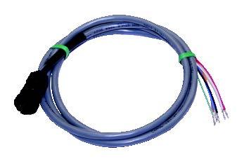
6 E. Wire the included MAC3 power/sensor shielded cable to the terminal strip supplied in the hardware bag. Terminal strip is marked 1-6, where: 1 = Red = +12VDC/24VDC 2 = Black = Common from Power Supply 3 = White = Sensor 1 (no polarity) 4 = Green = Sensor 1 (no polarity) 5 = Orange = Sensor 2 (optional, no polarity) 6 = Blue = Sensor 2 (optional no polarity) 6
7 F. Attach the MAC3 power/sensor shielded cable to the left socket and twist the cap to lock it in place. G. Apply proper voltage (12VDC to 24VDC) to terminals 1 and 2 of the terminal strip. Follow screen prompts on the MAC3 (see operating instructions). 7
8 H. Secure MAC3 indicator in a proper mounting location using the screws supplied in the hardware bag. Secure the terminal strip with the screws supplied in the hardware bag to ensure the wire connections are stable. The MAC3 indicator and anemometer are weather-tight to the IP65 standard and are rated for use from -40 F to 158 F (-40 C to 70 C). 8
9 Relay Cable With the relay cable (EA077) you have access to the output of two (2) 5A SPDT relays that can control external devices. To install: 1. Remove the waterproof cap on the right connector on the MAC3 indicator. 2. Plug the relay cable (EA077) into the connector. 9
10 Optional Equipment Dual Sensor Operation The MAC3 can be configured for simultaneous use with dual sensors to monitor wind speed in two separate locations. An optional second sensor (Kit-#400) can be installed to the orange and blue wires from the power/sensor cable. Follow the set up instructions to select 2 sensor operation. Other Optional Equipment Part #: EA065 Part #: WM033 Part #: WM030 Part #: EH110 12VDC Power Supply Conductor Shielded Cable 2-Conductor Shielded Cable sold by the foot, 1000 maximum length External Siren Operation Manual 1. Connect the MAC3 to a 12 or 24VDC power source per the installation instructions. a. MAC3 will conduct a self-test at initial power-up. Once complete, you will see the welcome screen (only for initial set up). 10
11 2. Keypad a. The MAC3 keypad allows the user to navigate through the screens and options of the wind speed alarm & controller. Up/Down Arrow Keys: BACK: CANCEL: DISPLAY: LEDs: Allows user to navigate through the options to select proper setting. Brings the user to the previous screen. Will cancel the selection and bring the user back to the Data display screen. Enable the main Menu while in the Data display screen. The left LED will turn on YELLOW when set-point 1 is reached as a visual aide. The right LED will turn on RED when set-point 2 is reached as a visual aide. 3. Guided Set-Up a. Follow the screen prompts through the set-up procedure. To cancel set-up mode, press the CANCEL button on the keypad at any time. Press the BACK button at any time to return to the previous step. Setting any feature to 0000 disables that function. 11
12 4. Select Units of Measure a. Using the up/down arrow keys scroll to select the desired UNITS (of measurement), press OK. 5. Select Sensors a. Using the up/down arrow keys, select the NUMBER OF SENSORS installed, press OK. 12
13 6. Set Points a. Using the up/down arrow keys, select the hundred s value for Set Point 1, press OK. b. Using the up/down arrow keys, select the ten s value for Set Point 1, press OK. c. Using the up/down arrow keys, select the one s value for Set Point 1, press OK. d. Using the up/down arrow keys, select the hundred s value for Set Point 2, press OK. e. Using the up/down arrow keys, select the ten s value for Set Point 2, press OK. f. Using the up/down arrow keys, select the one s value for Set Point 2, press OK. g. Follow Steps 1-6 if you selected the optional two sensor installation to set values for sensor Controller Lock The CONTROLLER LOCK feature allows the user to lock out unauthorized personnel from changing the controller settings. If the Lock Code is set and is then lost, the unit will need to be returned to the factory to reset the code. By pressing the CANCEL button, no Lock Code will be retained and the 13
14 MAC3 will display current conditions and settings. If the code is set to 0000, the lock feature will be disabled. a. Using the up/down arrow keys select the first number, press OK. b. Using the up/down arrow keys select the second number; press OK. c. Using the arrow keys select the third number, press OK. d. Using the arrow keys select the fourth number, press OK. Once the fourth number is set, the lock feature will be enabled. e. Enter an Employee number as a record of who entered the Lock Code. Using the up/down arrow keys select the first number, press OK. f. Using the up/down arrow keys select the second number; press OK. g. Using the up/down arrow keys select the third number, press OK. h. Using the up/down arrow keys select the fourth number, press OK. The MAC3 is now fully operational. Set-Point 1 controls relay #1, Set-Point 2 controls relay #2. Relays will activate when the wind speed reaches the selected SETPOINTS. When the wind speed reaches a single Set-Point, the buzzer will sound every second. When both Set-Points have been met, the buzzer will sound continuously. 14
15 MAC3 Data Display 1. With one (1) installed sensor a. When 1 installed sensor is selected, the display will show the current wind speed in the units of measurement previously selected; a running 1-minute average wind speed (unless the average was changed to 2, 5, or 10 minutes); the MAX wind gust since last reset, and the Set-Point values currently selected. b. When Set-Point 1 is reached, the buzzer will sound an alternating beep, the word TRIP will be highlighted on the display above the word LOW, and the yellow LED on the keypad will light. When Set- Point 2 is reached, the beep will become steady and the word TRIP will be highlighted on the display above the words LOW and HIGH, and the red LED on the keypad will light. c. Gust Reading: The MAX wind gust reading may be reset by pressing the OK and BACK buttons simultaneously. 2. With two (2) installed sensors 15
16 a. When an optional 2 sensor set up is used, the screen will split and display the current wind speed in the units of measurement selected for both sensors; a running 1-minute average (unless the average was changed to 2, 5, or 10 minutes); the MAX wind gust since last reset, and the Set-Point values selected for the individual Set-Points as SP1 and SP2. b. When Set-Point 1 is reached, the buzzer will sound an alternating beep and the word SP1 will change to TRIP, which will be highlighted, and the yellow LED on the keypad will light. When Set- Point 2 is reached, the beep will become steady and the word SP2 will change to TRIP, which will be highlighted, and the red LED on the keypad will light. This will be the same for sensors 1 and 2. c. Gust Reading: The MAX wind gust reading may be reset by pressing the OK and BACK buttons simultaneously. Additional Features The MAC3 Wind Speed Alarm & Controller has many features that can be customized for your particular installation. If the indicator s lock out feature has been enabled, you will need the unlock code prior to proceeding with changes. If the indicator s features have not been locked you will be able to access the MAIN MENU by pressing the DISPLAY button on the indicator. Please note that the screen will revert to the data display if it detects no keypad activity for 1 minute. 1. Changing the Unlock Code 16
17 a. Select CHANGE UNLOCK CODE using the up/down arrow keys, then press OK. A code of 0000 will disable the lock feature. If the MAC3 has been locked and the unlock code is not known, you can return the unit to Maximum to have the code reset. b. Using the up/down arrow keys, set the first number of the CURRENT CODE, press OK. c. Using the up/down arrow keys, set the second number of the CURRENT CODE, press OK. d. Using the up/down arrow keys, set the third number of the CURRENT CODE, press OK. e. Using the up/down arrow keys, set the fourth number of the CURRENT CODE, press OK. f. Using the up/down arrow keys, set the first number of the NEW CODE, press OK. g. Using the up/down arrow keys, set the second number of the NEW CODE, press OK. h. Using the up/down arrow keys, set the third number of the NEW CODE, press OK. i. Using the up/down arrow keys, set the fourth number of the NEW CODE, press OK. 17
18 j. Using the up/down arrow keys, set the first number of the EMPLOYEE CODE, press OK. k. Using the up/down arrow keys, set the second number of the EMPLOYEE CODE, press OK. l. Using the up/down arrow keys, set the third number of the EMPLOYEE CODE, press OK. m. Using the up/down arrow keys, set the fourth number of the EMPLOYEE CODE, press OK. MAC3 will return to the data display screen when the final number is entered. Display Adjustments 1. Brightness/Contrast: Adjust the brightness and contrast of the display using the buttons on the indicator. This feature will only work on the data display, not when inside one of the menus. a. To adjust Brightness, press and hold the BACK button on the indicator. Use the up/down arrow keys to adjust the display to the desired brightness level. b. To adjust Contrast, press and hold the CANCEL button on the indicator. Use the up/down arrow keys adjust the display to the desired contrast level. Wind Settings The MAC3 Wind Speed Alarm & Controller offers several user-selectable settings for wind speed measurement. The instructions below detail these setting options. 1. Units of Measure: Press the DISPLAY button to access the MAIN MENU. 18
19 a. Using the up/down arrow keys, select WIND SETTINGS on the Main Menu, press OK. b. Using the up/down arrow keys, advance to UNITS OF MEASURE, press OK. c. Using the up/down arrow keys, select the desired unit of measure, press OK. 19
20 2. Measurement Type: Choose the type of wind speed measurement that appears on the display. Choose from: CURRENT/PEAK, 1 MINUTE AVERAGE, 2 MINUTE AVERAGE, 5 MINUTE AVERAGE or 10 MINUTE AVERAGE. Press the DISPLAY button to access the MAIN MENU. a. Using the up/down arrow keys, select WIND SETTINGS from the Main Menu, press OK. b. Using the up/down arrow keys, advance to MEASUREMENT TYPE, press OK. 20
21 c. Using the up/down arrow keys, select the desired setting, press OK. d. When selecting an Alarm to operate on an average mode, the individual Set-Point will be controlled by the average time specified. For example: If the MAC3 is set to display wind speed over a 2 MINUTE AVERAGE, wind speeds will need to escalate until the 2- minute average reaches the previously determined Set-Point speed. The alarm will remain on until the 2-minute average drops below that Set-Point. 3. Installed Sensors: The MAC3 is capable of measuring 2 sensors simultaneously. Use this menu to select the number of sensors installed. Press the DISPLAY button to access the MAIN MENU. a. Using the up/down arrow keys, select WIND SETTINGS from the Main Menu, press OK. 21
22 b. Using the up/down arrow keys, advance to INSTALLED SENSORS, press OK. c. Using the up/down arrow keys, select the desired setting, press OK. Alarm & Control Settings The MAC3 Wind Speed Alarm & Controller can be used in various configurations. IMPORTANT: When using the MAC3 as aide to your safety program, it should only be used in either the NORMAL ALARM or LATCHING OUTPUTS mode. The RANGE ALARM and TIME DELAY OUTPUT modes are suitable when the MAC3 is being used as a controlling device only. 1. Normal Alarm: Use this feature to customize the Set-Points of the MAC3. In NORMAL ALARM mode, the alarm and relay Set-Point will activate when the wind speed reaches the Set-Point value. The alarm and relay will deactivate when the wind speed drops below the same Set-Point. 22
23 a. Press the DISPLAY button to access the Main Menu. b. Using the up/down arrow keys, select ALARM & CONTROL SETTINGS, press OK c. Using the up/down arrow keys, select NORMAL ALARM, press OK. d. Using the up/down arrow keys, set the first number of SENSOR 1, SET POINT 1, press OK. 23
24 e. Using the up/down arrow keys, set the second number of SENSOR 1, SET POINT 1, press OK. f. Using the up/down arrow keys, set the third number of SENSOR 1, SET POINT 1, press OK. g. Using the up/down arrow keys, set the first number of SENSOR 1, SET POINT 2, press OK. h. Using the up/down arrow keys, set the second number of SENSOR 1, SET POINT 2, press OK. i. Using the up/down arrow keys, set the third number of SENSOR 1, SET POINT 2, press OK. If you have a second sensor installed follow the same procedure to set for Normal Alarm Sensor Range Alarm: In RANGE ALARM mode, both the alarm and relay will activate at the selected ON SPEED set point. They will remain active until the wind speed reaches the OFF SPEED set point. The MAC3 can be used as two types of range alarms: 1.) A window comparison where the On Set-Point is less than the Off Set-Point, or as a comparison with hysteresis where the On Set-Point is greater than the Off Set-Point. a. Using the up/down arrow keys, select RANGE ALARM in ALARM & CONTROL SETTINGS, press OK. 24
25 b. Using the up/down arrow keys, set the first number of SENSOR #1, ON SPEED, press OK. c. Using the up/down arrow keys, set the second number of SENSOR #1, ON SPEED, press OK. d. Using the up/down arrow keys, set the third number of SENSOR #1, ON SPEED, press OK. e. Using the up/down arrow keys, set the first number of SENSOR # 1, OFF SPEED, press OK. f. Using the up/down arrow keys, set the second number of SENSOR #1, OFF SPEED, press OK. g. Using the up/down arrow keys, set the third number of SENSOR #1, OFF SPEED, press OK. If a second sensor is installed, follow the same procedure to set for RANGE, SENSOR #2. 3. Time Delayed Outputs: In TIME DELAY mode, the alarm and relay will activate when the Set-Point is reached. Both will remain active for a specified period of time. After that time has elapsed, if the wind speed remains higher than the Set-Point, the timer will reset and continue the delay for the same period of time. Otherwise, it will return to a normal state. 25
26 a. Using the up/down arrow keys, select TIME DELAYED OUTPUTS in ALARM & CONTROL SETTINGS, press OK. b. Using the up/down arrow keys, set the hours delay for SENSOR #1, OUTPUT #1, press OK. c. Using the up/down arrow keys, set the minutes delay for SENSOR #1, OUTPUT #1, press OK. d. Using the up/down arrow keys, set the seconds delay for SENSOR #1, OUTPUT #1, press OK. e. Using the up/down arrow keys, set hour delay for SENSOR #1, OUTPUT #2, press OK. f. Using the up/down arrow keys, set the minutes delay for SENSOR #1, OUTPUT #2, press OK. 26
27 g. Using the up/down arrow keys, set the seconds delay for SENSOR #1, OUTPUT #2, press OK. If a second sensor is installed, follow the same procedure to set TIME DELAY for SENSOR #2. 4. Latching Outputs: In the LATCHING OUTPUTS mode, both the alarm and relay will activate at the level you set, and will remain active until the operator releases the latch. To release the latch, press the OK button and UP arrow simultaneously. The latching value will be equal to the SET POINT 1 setting made during the NORMAL ALARM setting procedure. a. Using the up/down arrow keys to select LATCHING OUTPUTS in ALARM & CONTROL SETTINGS, press OK. b. Using the up/down arrow keys, set the desired LATCH mode, press OK. 27
28 If a second sensor is installed, follow the same procedure to set a LATCH for SENSOR #2. 5. Sound: You can Enable or Disable the built in buzzer. Note: In safety sensitive installations, the buzzer can be a valuable feature. You may also connect a louder external siren (EH110 or EH111) and have it controlled by the external relays. a. Using the up/down arrow keys, select SOUND in ALARM & CONTROL SETTINGS, press OK. b. Using the up/down arrow keys, select the desired ENABLED or DISABLED setting, press OK. 28
29 Tests The MAC3 Wind Speed Alarm & Controller has built-in test routines that assist with troubleshooting the instrument. Press the DISPLAY Button to reach the MAIN MENU and using the up/down arrow keys, select TESTS, press OK. 1. Sensor/Cable Status: Using the up/down arrow keys, select SENSOR/CABLE STATUS, press OK. 29
30 a. The MAC3 will run a continuous test on the sensors/cables, and display the results. Press the CANCEL button at any time to return the system to normal operation. 2. Test Outputs: Using the up/down arrow keys select TEST OUTPUTS, press OK. a. Using the up/down arrow keys, select LEFT LED, press OK to toggle the left LED on and off. b. Using the up/down arrow keys, select RIGHT LED, press OK to toggle the right LED on and off. c. Using the up/down arrow keys, select RELAY 1, press OK to toggle relay 1 output on and off. d. Using the up/down arrow keys, select RELAY 2, press OK to toggle relay 2 output on and off. 30
31 e. Using the up/down arrow keys, select BUZZER, press OK to toggle the buzzer sound on and off. Press the CANCEL button at any time to return the system to normal operation. 3. System Status: This feature will display system specifics such as operating temperature, firmware version, etc. Using the up/down arrow keys, select SYSTEM STATUS, press OK. 31
 to -70 C (158 F). The MAC3 will shut down if it exceeds these temperatures.")
32 a. Once System Status has been selected, the MAC3 will display its current SYSTEM STATUS on the screen. Press the CANCEL button at any time to return the system to normal operation. Troubleshooting Please note, the operating temperature of the MAC3 is -40 C (-40 F) to -70 C (158 F). The MAC3 will shut down if it exceeds these temperatures. Prior to reaching these temperatures, the screen will show a warning to alert the user. 1. No Display: Check to make sure that the power supply is connected and verify its rated output with a multi-meter. If still no display, unplug the power cord from the MAC3, wait 5 minutes and re-apply power. a. When the ambient temperature is close to an operating limit, the MAC3 internal temperature may fall outside of the limit and it will not be able to power up. If the ambient temperature is less than -22 F /-30 C or greater than +140 F/+60 C, warm or cool the MAC3 and then re-try powering up. 32
33 2. Sensor/Cable failure: If the wind speed display changes to CONTINUITY TEST FAILURE HIGH RESISTANCE, or HIGH OHMS in 2-sensor operation, check to ensure that there are no breaks in the cable. To test the sensor, disconnect the cable and, using a multi-meter, measure the resistance across the terminals of the sensor. If the sensor is good it will show aprroximately 700 ohms. 3. Change Lock Code Screen: If the entered old code is wrong, then the screen values are all reset to zero and the first digit of the old code value is re-selected. Specifications Measurement range: Accuracy: Sample Rate: 0 255MPH ± 2 MPH of input and ± 1 digit 1.7 seconds Sound: 85 db(a)/10cm 3.1kHz, -40 to 70 C Relays: Operating Temperature: Power: Current Draw: Sensor: Dimensions: Two SPDT relays (rated at 5A at 30VDC) -40 to +158 F (-40 to +70 C) 150mA; 75mA 120mA Max with heater off 970mA Max with heater on 3-Cup #400 anemometer 7.39 height x 5.08 width x 2.26 depth Viewing Display: x Weight: 1.3 LBS 33
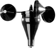


34 Components #400 Anemometer Power Cable 100 Shielded Sensor Cable Rubber Sensor Boot 14 Stainless Steel Mast Mounting Hardware 34
35 30 Samuel Barnet Boulevard New Bedford, MA (508)
M A C 3 Wind Speed Alarm & Controller
 M A C 3 Wind Speed Alarm & Controller Installation Instructions Thank you for purchasing the MAC3 wind speed alarm and controller. This manual is designed to lead you through a step-by-step process to
CF3000 Dealer Diagnostic Tool Instruction Manual
 CF3000 Dealer Diagnostic Tool Instruction Manual Table of Contents: About the CF3000......3 Important Precautions......4 Components....5 Charging the CF3000......7 Licensing the CF3000.......8 Updating
M2 OLED Temperature Monitor Instructions PN 1841
 M2 OLED Temperature Monitor Instructions PN 1841 Installation Checklist Check for components included Read Warning and Cautions Read page 3 for mounting instructions Read System Overview, Mounting Considerations,
AC M2 OLED Meter Instructions PN 1836/ PN 1837 / PN 1838
 AC M2 OLED Meter Instructions PN 1836/ PN 1837 / PN 1838 Installation Checklist Check for components included Read Warning and Cautions Read QuickStart Installation Guide for mounting instructions Read
Digital Keypad Introduction
 K2 Digital Keypad Introduction The K02 uses the latest microprocessor technology to operate door strikes and security systems that require a momentary (timed) or latching dry contact closure. All programming
4. How to Connect the Fixture 3-Pin and 5-Pin XLR DMX Connectors:
 TABLE OF CONTENTS 1. Safety Instructions 2. Technical Specifications 3. Installation 4. How to Connect the Fixture 5. DMX512 Configuration 6. DMX512 Connections 7. How to Set the Unit 8. Troubleshooting
IPM650 Intelligent Panel-Mount Display
 Quick Start Guide IPM650 Intelligent Panel-Mount Display Sensor Solutions Source Load Torque Pressure Multi Component Calibration Instruments Software www.futek.com Getting Help TECHNICAL SUPPORT For more
Instruction Manual. M Pump Motor Controller. For file reference, please record the following data:
 Instruction Manual M Pump Motor Controller For file reference, please record the following data: Model No: Serial No: Installation Date: Installation Location: When ordering replacement parts for your
5450 NW 33rd Ave, Suite 104 Fort Lauderdale, FL Fruitland Ave Los Angeles, CA UM Channel Monitor.
 5450 NW 33rd Ave, Suite 104 Fort Lauderdale, FL 33309 3211 Fruitland Ave Los Angeles, CA 90058 UM-600 6-Channel Monitor Version 2 Installation and Operation Manual Rev. G P/N145F-12990 PCO 00007462 (c)
TOUCHLOCK compact. Master code: Paxton Access Ltd. ins TOUCHLOCK compact kit. Document Contents. Instructions for the following:
 ins-016 160499 TOUCHLOCK compact 100-050 TOUCHLOCK compact kit Instructions for the following: 526-886 TOUCHLOCK compact keypad 100-050 TOUCHLOCK compact kit Master code: Document Contents About this product...2
MYRIAD QLC 4-CHANNEL MONITOR/CONTROLLER INSTRUCTION MANUAL
 MYRIAD QLC 4-CHANNEL MONITOR/CONTROLLER INSTRUCTION MANUAL VISIT OUR WEBSITE SIGMACONTROLS.COM MYR QLC MANUAL 013114 2 TABLE OF CONTENTS INTRODUCTION 3 Ordering Information Specifications Features WIRING
MINI-MAX WIRELESS. RECEIVER WIRING WHITE...to...TERMINAL #1
 MINI-MAX INSTALLATION THIS MANUAL IS DESIGNED TO LEAD YOU STEP BY STEP THROUGH THE PROCEDURES REQUIRED TO TEST, INSTALL AND USE YOUR MINI-MAX. BY FOLLOWING THESE PROCEDURES AND SETTING UP THE SYSTEM CORRECTLY
DIRECT POWER LIGHTING MANUAL
 SS2 -RGBW RGBW-18L DIRECT POWER LIGHTING MANUAL Coloronix, Inc. 5461 West Jefferson Boulevard Los Angeles, California 90016 (323) 677-4242 http://www.rgbw.com Summary Introduction RGB Color Changing Adjustable
TC-9102 Series Surface Mount Temperature Controllers
 TC-9102 Series Surface Mount Temperature Controllers General Description & Applications The TC-9102 Series Temperature Controller offers a versatile solution for a wide variety of applications that may
SL2000E. Status Output. Electronic Code Lock. Features. Input. Exit Button Input. Introduction. Door Contact Input. Functional Description.
 SL2000E Electronic Code Lock Features Door Relay output Status transistor output Aux transistor output Door Contact input Exit Button input INSTALLER code for programming MASTER code for arming/disarming
the Interactive Catalog
 Interactive Catalog Supplements Catalog PDFs If you need detailed product information, or help choosing the right product for your application, see our Interactive Catalog Use the Interactive Catalog to
TARA CONTROLS AGC-5. UCI Random Start USER S GUIDE. With Optional Warning Flashes for the Hearing Impaired. TARA CONTROLS by Cartessa Corporation
 TARA CONTROLS AGC-5 UCI Random Start USER S GUIDE With Optional Warning Flashes for the Hearing Impaired TARA CONTROLS by Cartessa Corporation 4825 Cincinnati-Brookville Road Shandon, Ohio 45063 Phone:
RAINWATCH WIRELESS RECEIVER WIRING
 RAINWATCH INSTALLATION THIS MANUAL IS DESIGNED TO LEAD YOU STEP BY STEP THROUGH THE PROCEDURES REQUIRED TO TEST, INSTALL AND USE YOUR RAINWATCH. BY FOLLOWING THESE PROCEDURES AND SETTING UP THE SYSTEM
M2 OLED Tank Monitor Instructions PN 1839
 M2 OLED Tank Monitor Instructions PN 1839 Installation Checklist Check for components included Read Warning and Cautions Read QuickStart Installation Guide for mounting instructions Read System Overview,
INSTALLATION INSTRUCTIONS
 CONSOLE CONNECTOR KIT 7830 FOR USE WITH: LESLIE Speaker Model 130 Various single and double channel organs INSTALLATION INSTRUCTIONS KIT CONTENT Console Connector 137283 Switch Assembly, Cable Assembly,
Keypad Lock. Operation and Service Manual. Order parts online
 Keypad Lock Order parts online www.follettice.com Operation and Service Manual 801 Church Lane Easton, PA 18040, USA Toll free (800) 523-9361 (610) 252-7301 Fax (610) 250-0696 www.follettice.com 00163345R00
e-ask electronic Access Security Keyless-entry OEM / Dealer / Installer Cargo Lock / Unlock Version Installation & Instructions (UM04 ~ )
") e-ask electronic Access Security Keyless-entry OEM / Dealer / Installer Cargo Lock / Unlock Version Installation & Instructions (UM04 ~ 18990-04) Table of Contents Introduction... 1 e-fob Operation and
e-ask electronic Access Security Keyless-entry OEM / Dealer / Installer Cargo Lock / Unlock Version Installation & Instructions (UM04 ~ 18990-04) Table of Contents Introduction... 1 e-fob Operation and
Relay Switch. Relay Ports. Front. Do not use this sensor in hazardous (classified) locations or life safety applications.
 locations or life safety applications.") AVTECH Switch AVTECH s Switch turns on and off up to 4 electrical devices. You may individually control each of the 4 relay outputs separately. Switch Package Contents One (1) Switch Two (2) mounting screws
AVTECH Switch AVTECH s Switch turns on and off up to 4 electrical devices. You may individually control each of the 4 relay outputs separately. Switch Package Contents One (1) Switch Two (2) mounting screws
Click Save to return to the main Setup screen.
 ON-SITE Setup Guide Thank you for purchasing the ON-SITE. This guide will assist you in the setup of the system. You can call for FREE technical support to get help anytime at 757-258-0910. Please note,
2000 Series e/em Style Keypad Installation and Programming Manual
 2000 Series e/em Style Keypad Installation and Programming Manual Document Number: 6054022 Revision: 0 Date: 12/21/06 Table of Contents Table of Contents Section 1: Introduction... 6 1 Product Description...6
Holland Computers, Inc. Crane Kit Manual Part Number RA-CRANE-KIT
 Holland Computers, Inc. Crane Kit Manual Part Number RA-CRANE-KIT SECTION 1 - Introduction Description This kit has been manufactured as a replacement gantry and electronics for existing machines using
BEP 600-ACSM AC SYSTEMS MONITOR. Installation and Operating Instructions. Page 1
 BEP 600-ACSM AC SYSTEMS MONITOR Installation and Operating Instructions Page 1 This page has been deliberately left blank Page 2 Table of Contents 1. BASICS 4 WARNING AND CAUTION 4 WARNING 4 CAUTION 4
CDD4 Duct Carbon Dioxide Transmitter
 Drill or punch a 1-1/8 or 1-1/4 hole in the duct at the preferred location and insert the probe into the hole to mark the enclosure mounting holes. Remove the unit and drill the four mounting holes. Clean
Operating and installation instructions Differential pressure monitor
 Operating and installation instructions Differential pressure monitor RM-DPC Micro SensorLine Table of contents 1 Safety instructions...3 2 Equipment specification...3 3 Assembly...4 4 Step-by-step installation...4
Installation, Start-up and Operating Instructions
 Installation, Start-up and Operating Instructions EVOLUTION SMART SENSOR FOR ZONING Cancels: NEW II ZONESMS-0-1 7-04 NOTE: Read the entire instruction manual before starting the installation. This symbol
Quick Start Guide. Preparation. Installation. Operation. Support. Vaisala NOMAD 3 Data Logger. Online manuals
 Quick Start Guide www.vaisala.com Vaisala NOMAD 3 Data Logger Preparation Package Contents Plan Instrumentation Create a SkyServe Account Activating the Nomad 3 Nomad 3 Toolbox Create Setup Files 2 4 5
AX3000 Platine Terminal Ethernet TCP/IP
 AX3000 Platine Terminal Ethernet TCP/IP Model 80WMS Installation Guide January 2012 - Ref: I80ME0922-2 Model AX3000/M80M Type EA The reproduction of this material, in part or whole, is strictly prohibited.
DC M2 OLED Meter Instructions PN 1830 / PN 1832 / PN 1833 / PN 1834
 DC M2 OLED Meter Instructions PN 1830 / PN 1832 / PN 1833 / PN 1834 Installation Checklist Check for components included Read Warning and Cautions Read QuickStart Installation Guide for mounting instructions
Model KT 53 Cooling incubators with thermoelectric cooling
 Model KT 53 Cooling incubators with thermoelectric cooling The KT series combines outstanding performance with impressive energy efficiency and environmental friendliness. The cooled incubators of the
Echotouch, EchoSpan & EchoSwitch Ultrasonic Liquid
 Echotouch, EchoSpan & EchoSwitch Ultrasonic Liquid The Echotouch, EchoSpan and EchoSwitch are innovative ultrasonic liquid level sensor families that replace float, conductance and pressure sensors that
EcoFlex LED Neon Manual
 Manual Part number: LN-ECO-XXXX-10m from Environmental Lights is one of the most flexible and cost-effective members of our line of LED Neon products. It allows you to achieve the creative potential of
Signet Pressure Transmitter
 Signet 850 Pressure English *850.090* 850.090 Rev. H /06 English CAUTION! Remove power to unit before wiring input and output connections. Follow instructions carefully to avoid personal injury. Contents.
Plus-X 300. Installation and Operation Manual
 Plus-X 300 Installation and Operation Manual Table of Contents Introduction... 1 Compatibility... 1 Installation... 1 Configuration... 2 Operation... 5 Getting Help... 6 Warranty... 6 Appendix A: Specifications...
Quick Start Installation and User Manual
 1 Quick Start Installation and User Manual Contents 1. Overview 2. Technical Specifications 3. Installation Mounting Electrical Installation Clamp Installation Wiring Diagrams 4. Installation Settings
+GF+ SIGNET 5800CR Conductivity/Resistivity Monitor Instructions
 GF SIGNET 5800CR Conductivity/Resistivity Monitor Instructions ENGLISH 35800CR.0901 D1/98 CAUTION! Refer to instruction manual for more details. Remove power to unit before wiring input and output connections.
8000 Series: Installation Supplement R2-1-12
 8000 Series: Installation Supplement R2-1-12 Smartscan Incorporated, 33083 Eight Mile Road, Livonia MI 48152 Tel: (248) 477-2900 Fax: (248) 477-7453 Web: www.smartscaninc.com SMARTSCAN INCORPORATED Livonia,
Omni. User Manual. Economic Self-Tune PID Temperature Controller. Omni 96. Omni 72 72X72. Omni ~ 265 V AC SUPPLY
 Omni Economic Self-Tune PID Temperature Controller Omni 7 Omni 4 6 5 4 3 1 7X7 7 1 11 5 ~ 65 V AC SUPPLY Omni 6 CONTENTS 1. PANEL MOUNTING & ELECTRICAL CONNECTIONS 1. FRONT PANEL : LAYOUT AND OPERATION
INSTRUCTION MANUAL DIGI-LOCK. Keyless Entry System. Installation. Programming. Troubleshooting. BASE Industries
 INSTRUCTION MANUAL DIGI-LOCK Keyless Entry System Installation Programming Troubleshooting BASE Industries 45 Pomona Rd. Corona, CA. 9880 Revision F TABLE OF CONTENTS OWNER REGISTRATION CARD INTRODUCTION
User Manual. Heavy Duty Hot Wire CFM Thermo-Anemometer. Model
 User Manual Heavy Duty Hot Wire CFM Thermo-Anemometer Model 407119 Introduction Congratulations on your purchase of the Extech 407119 Thermo-Anemometer. The 407119 measures air velocity, air volume, and
Stock Weigh 300. Operators Manual HELLO. Ft. Atkinson, Wisconsin USA. Panningen, The Netherlands
 Stock Weigh 300 Operators Manual HELLO Ft. Atkinson, Wisconsin USA Panningen, The Netherlands www.digi-star.com D3734-US REV E October 31 st, 2012 SW300 User s Manual D3734-US REV E TABLE OF CONTENTS Table
T4HD: Installation Supplement R8.1.13
 THD: Installation Supplement R8.. Smartscan Incorporated 08 Eight Mile Road Livonia MI 8 Tel: (8)77-900 Fax: (8) 77-7 Web: www.smartscaninc.com Smartscan Incorporated Livonia, Michigan THD The use of this
6-Channel Monitor. Installation and Operation Manual
 3211 Fruitland Ave Los Angeles, CA 90058 Catalyst Monitor 6-Channel Monitor Version 2 Installation and Operation Manual Rev. H P/N145F-12964 PCO - 00009743 (c) Copyright 2015, Barksdale, Inc. All Rights
GCI-5K INSTALLATION AND OPERATOR S MANUAL
 GCI-5K INSTALLATION AND OPERATOR S MANUAL Grid-tied inverter for wind Ningbo Ginlong Technologies 1 INTRODUCTION 2 SAFETY GUIDELINES AND WARNINGS 3 INSTALLATION 3.1 Selecting a location for the inverter
Progressive Industries, Inc. EMS Electrical Management System
 Progressive Industries, Inc. EMS Electrical Management System Complete Installation Guide and Operating Instructions for: Model EMS-LCHW50 Rated at 240V/50A Manufactured by: Progressive Industries, Inc.
CDD Carbon Dioxide Transmitter
 Introduction The OSA CO2 transmitter uses Infrared Technology to monitor CO2 levels within a range of 0 2000 ppm and outputs a linear 4-20 ma or 0-5/0-10 Vdc signal. The enclosure is designed to operate
WARNING!!!!!!!!! IMPORTANT INFORMATION: READ BEFORE INSTALLATION!
 V_Net Relay Module Installation Instructions: Part Number: 230-VM-RELAY WARNING!!!!!!!!! IMPORTANT INFORMATION: READ BEFORE INSTALLATION! The relay outputs of the 230-VM-RELAY module may turn on when not
212iL Rev. 1.1
 212iL 1 International Electronics, Inc. 427 Turnpike Street Canton, Massachusetts 02021 212iL (illuminated Luxury) Keypad Single Unit Keypad- Control Installation Manual Features: 120 User Capability Illuminated
VR2 R-NET LED R-NET LCD. Controller System Operation
 VR2 R-NET LED R-NET LCD Controller System Operation 1.VR2 Controller Operation 1.1 Controls/JSM 1.2 Button/Indicator 1.3 Control System Status indication 1.4 Module Wiring 1.5 VR2 Locking / Unlocking The
MODEL 8000MP LEVEL SENSOR
 1 MODEL 8000MP LEVEL SENSOR INSTRUCTIONS FOR INSTALLATION, OPERATION & MAINTENANCE VISIT OUR WEBSITE SIGMACONTROLS.COM 2 SERIES 8000MP LEVEL SENSOR 1. DESCRIPTION The Model 8000MP Submersible Level Sensor
User Manual. PCKeypad Wireless Keypad
 User Manual PCKeypad Wireless Keypad Description The PCKeypad is a wireless keypad with a PentaCODE transmitter built-in. It works with all of Elsema s PCR series receivers. The installer has the option
Single Door Standalone Access Control User Manual
 Single Door Standalone Access Control User Manual Reading this manual carefully before install and use the device 1. Packing List Name Quantity Remarks Keypad User manual Screw driver Rubber plug Self
CO-485USB USB to RS-485 CONVERTER TECHNICAL REFERENCE
 TABLE OF CONTENTS CO-485USB USB to CONVERTER TECHNICAL REFERENCE Specifications, Description and Technical Support... page 1 Connection Diagram... page 2 Set-Up & Testing... page 3 & 4 Power Supply Shunts...
INSTALLATION INSTRUCTIONS Model 930 EntryCheck
 SECURITY DOOR CONTROLS 3580 Willow Lane, Westlake Village, CA 91361-4921 (805) 494-0622 Fax: (805) 494-8861 www.sdcsecurity.com E-mail: service@sdcsecurity.com INSTALLATION INSTRUCTIONS Model 930 EntryCheck
Installation Manual. 65 Interactive LED/LCD. Model: HILF65101 (64.56 )
") Installation Manual 65 (64.56 ) Model: HILF65101 65 Interactive LED/LCD QUICK SETUP GUIDE For further information, see the user manual. Please contact directly if you have questions on the use of the touch
Installation Manual 65 (64.56 ) Model: HILF65101 65 Interactive LED/LCD QUICK SETUP GUIDE For further information, see the user manual. Please contact directly if you have questions on the use of the touch
Instruction Manual. Electrical Management System (EMS) EMS-HW30C & EMS-HW50C
 EMS-HW30C & EMS-HW50C") Instruction Manual Electrical Management System (EMS) EMS-HW30C & EMS-HW50C EMS-HW50C EMS-HW30C! CAUTION These instructions are intended to provide assistance with the installation of this product, and
Instruction Manual Electrical Management System (EMS) EMS-HW30C & EMS-HW50C EMS-HW50C EMS-HW30C! CAUTION These instructions are intended to provide assistance with the installation of this product, and
KP2000E/EM Series Style Keypad
 23852973 KP2000E/EM Series Style Keypad Installation and Programming Instructions Models KP2000EXX and KP2000EMXX Specifications Parameter Voltage Requirements Keypad Current Requirements (Max) Relay Contact
DG-800 Stand-Alone Proximity Reader Instruction Manual
 DG-800 Stand-Alone Proximity Reader Instruction Manual I. Features 1. Memory volume up to 1000+10 proximity cards/tokens and PINs with the programming time up to 0.5 seconds. 2. Access modes: a. Only Proximity
ADC7520 SERIES. 1600W Battery Chargers and Power Supplies
 ADC7520 SERIES 1600W Battery Chargers and Power Supplies Wide output adjustment range 0 72VDC Analog control by external 0-5VDC voltage Temp.comp charging, sense as on option Power fail relay alarm Master-Slave
NETRONICS HS3500 CONTROLLER
 NETRONICS HS3500 CONTROLLER CUSTOMER NAME CONTROLLER SERIAL # CONTROLLER PART # PERSONALITY SWITCH SETTINGS BULLET PRESS CONFIGURATION DELIVERY DATE Contact the factory for help setting up your application.
SINAMICS G130. Terminal Module 150 (TM150) Operating Instructions 03/2013 SINAMICS
 Operating Instructions 03/2013 SINAMICS") SINAMICS G130 Operating Instructions 03/2013 SINAMICS s Safety information 1 General information 2 SINAMICS SINAMICS G130 Mechanical installation 3 Electrical installation 4 Technical specifications 5
SINAMICS G130 Operating Instructions 03/2013 SINAMICS s Safety information 1 General information 2 SINAMICS SINAMICS G130 Mechanical installation 3 Electrical installation 4 Technical specifications 5
Cellular Alert PRO PRODUCT MANUAL
 Cellular Alert PRO PRODUCT MANUAL Item # 3451, 3452, and 3453 Family of devices CONTENTS General Overview 3 Contents 3 Specifications 4 Important SIM Card Information 5 Setup 6 Sensor 8 Battery Setup 9
ULTRASTAT23 Operating Instructions For the MEC-110 with ENHANCED SMS 10-Product Cooking Controller
 ULTRASTAT23 Operating Instructions For the MEC-110 with ENHANCED SMS 10-Product Cooking Controller THIS APPLIANCE IS FOR PROFESSIONAL USE AND IS TO BE USED ONLY BY QUALIFIED PERSONNEL 302 Spencer Lane
1. Installation. 2. Configuration - Operation. 3. Specifications. Safety
 Safety 1. Installation 1.1 OP_ext: Services 1.2 Driver Card Installation 1.3 Sensor Types 1.4 Sensor Wiring 1.5 Controller Wiring 2. Configuration - Operation 2.1 Replaces ph Sensor 2.2 AS -Flex Series
Installing Keypad and Backplate
 Installing Keypad and Backplate Fig.1 Positioning of Fixing Holes and Cable Outlet Cable Outlet, Drill Diameter 10mm for Cable Access Remove the back plate, which is fitted to rear of the keypad, using
Installation and Start-Up Instructions
 EVERVU Touch Screen Display for EVERGREEN 19XR,XRV, 23XRV Chillers with PIC II or PIC III Controls Installation and Start-Up Instructions Part No: 33CNTVIEW CONTENTS SAFETY CONSIDERATIONS......................
Waterproof. Keypad/Reader/Controller
 Waterproof Keypad/Reader/Controller User Manual W1-C W3-C User manual 1. Packing List Name Quantity Remarks Digital Keypad-W1-C/W3-C 1 User manual 1 Screw driver 1 Rubber bungs 4 6*27mm, used for fixing
Standalone Keypad Access Control. User Manual. SS-TS2000 Size:120*80*25 mm
 Standalone Keypad Access Control User Manual SS-TS2000 Size:120*80*25 mm Please read the manual carefully before use this unit 1. Packing List Name Quantity Remarks Keypad 1 User manual 1 Screw driver
AirTest Model CN9000 Series Sensor Controller
 AirTest Model CN9000 Series Sensor Controller AirTest Model CN9000 Series Sensor Controller THEORY OF OPERATION A basic CN9000 configuration consists of Input/Process/Display combination modules, a 3 relay
KOBOLD Compact Electronics
 KOBOLD Compact Electronics User Instructions KOBOLD Instruments Inc. 1801 Parkway View Drive Pittsburgh PA 15205 Phone (412) 788-2830 Fax (412)-788-4890 www.koboldusa.com Manual-compactelectronics_2262002
Instruction Manual CTC-1
 Troubleshooting & Specs CTC-1 Amps / Volts requirements Min / Max operating temperature Min / Max operating Humidity Temperature Measurement range Temperature Accuracy CO2 sensor type CO2 Measurement range
RT2Y Compact temperature switch intrinsic safety
 ompact temperature switch intrinsic safety Main Features Excellent repeatability Fix dead band for control and alarm Resistant to accidental overtemperature Intrinsic safety Hazardous area 0, 1, 2 pplications
TABLE OF CONTENTS 1. Safety Instructions 2. Technical Specifications 3. Installation 4. How to Connect the Fixture 5. DMX512 Connections 6.
 TABLE OF CONTENTS 1. Safety Instructions 2. Technical Specifications 3. Installation 4. How to Connect the Fixture 5. DMX512 Connections 6. How to Set the Unit 7. DMX Configuration 8. IR Remote Control
CDD4 Series Room CO2 Transmitter Installation Instructions
 CDD4 Series Room CO2 Transmitter Installation Instructions Introduction The CO2 transmitter uses Infrared Technology to monitor CO2 levels and outputs a linear 4-20 ma or 0-5/0-10 Vdc signal. Options include
ETC Installation Guide
 ColorSource PAR v1.7 Overview The ColorSource PAR is an affordable LED fixture that uses the RGB-L (red, green, blue, and lime) color system to provide a rich, bright light. The ColorSource PAR is available
CV-550SPK V2 Waterproof Keypad/Reader/Controller Installation Instructions
 CV-550SPK V2 Waterproof Keypad/Reader/Controller Installation Instructions Packing List NAME MODEL/SIZE QTY Self tapping screw 0.15 x 1.06 (4mm 27 mm) Rubber plug 0.23 x 1.2 (6mm 30 mm) Star screw driver
SERIES CMT CARBON MONOXIDE GAS TRANSMITTER
 SERIES CMT CARBON MONOXIDE GAS TRANSMITTER INSTALLATION OPERATION AND MAINTENANCE MANUAL DWYER INTRUMENTS, INC. PO BOX 373, MICHIGAN CITY, IN. 46360 USA PHONE: 800-872-9141 FAX: 219-872-9057 Web: www.dwyer-inst.com
CARLO GAVAZZI Automation Components
 CARLO GAVAZZI Automation Components UDM 35/40 Digital Panel Meter Programming Guide Index Description 2 Programming Fundamentals 3 Access to Programming Mode/Password Protection 4 Programming 5-18 Inputs
Series SD-3PB Digital THERMOSTAT + TIMER
 SD-3PB Thermostat and Interval Timer in one Unit. This microcomputer based controller consists of two sections: The Digital Timer and Digital Thermostat, working together to control the power switched
NOTE: Read the instructions completely through before beginning actual installation.
 CONSOLE CONNECTOR KIT 7850 INSTALLATION INSTRUCTIONS FOR USE WITH: Various Two-channel Organs LESLIE Speaker Models 705, 705C, 720 KIT CONTENT Console Connector 138488 Switch Assembly, Cable Assembly,
Section 11. Electrical System. 42--CF200--MA--09 (formerly 42-65) Issued 5/96 P/N B. E 1996 Nordson Corporation All rights reserved
 Issued 5/96 P/N B. E 1996 Nordson Corporation All rights reserved") ection 11 Electrical ystem 11-0 Electrical ystem Table of Contents i Table of Contents ection 11 Electrical ystem 1. Introduction... 11-1 Electrical Operation... 11-2 Heating Zones... 11-2 2. Electrical
ection 11 Electrical ystem 11-0 Electrical ystem Table of Contents i Table of Contents ection 11 Electrical ystem 1. Introduction... 11-1 Electrical Operation... 11-2 Heating Zones... 11-2 2. Electrical
CP150B Vandal & Weather Resistant Keypad Security Systems
 Vandal & Weather Resistant Keypad Security Systems EN Security System CP150B - Vandal & Weather Resistant Keypad The CP150B keypad provides alarm and or access control functionality when used on selected
ABM International, Inc. Lightning Stitch Checklist 9/13/2013
 ABM International, Inc. Lightning Stitch Checklist 9/13/2013 1) Piggy backed board assembly (1) Piggy back board assembly tested? Yes No 24v passed XB passed XA passed YB passed YA passed SAFE passed S/S
Panel Indicators. NEW 4~20mA Panel Display. Process Indicators INTECH INSTRUMENTS.
 The LPI-LCD-6-4~20mA panel display is ideal for displaying a variety of process variables, and is easy to scale to your required engineering units. LPI-LCD-6 4~20mA Panel Display. Loop powered. Loop powered
Secured Series: Hub Plus Kit Single Door Controller Package Installation Manual
 Secured Series: Hub Plus Kit Single Door Controller Package Installation Manual This package is designed to simplify the connections to our Secured Series Hub Plus Controller. This will translate into
Omni + User Manual. Dual Setpoint Temperature Controller with Programmable Input & TIMER. Omni 96+ Omni 72+ Omni 48+ TMR TMR TMR
 Omni + Dual Setpoint Temperature Controller with Programmable Input & TIMER Omni 72+ Omni 48+ TMR TMR Omni 96+ TMR CONTENTS 1. PANEL MOUNTING & ELECTRICAL CONNECTIONS 1 2. FRONT PANEL : LAYOUT AND OPERATION
Partizan PAB-FC2. Fingerprint scan time Fingerprint identification time. <0.5 s < % <0.0198% Ingress protection rating
 1. Features & Technical Parameters 1.1 Features: Partizan PAB-FC2 Metal vandalproof housing Secure and reliable biometric fingerprint recognition Simple for using, wiring can be done by a user without
CII: Current Input, Isolated
 Safety 1. Application CII Driver Card 2. Installation 2.1 Services 2.2 Driver Card Installation 2.3 Driver Wiring 3. Configuration - Operation 3.1 Diagnostics 3.2 Calibration 4. Specifications Safety Electrical
Heavy Duty Hot Wire CFM Thermo-Anemometer
 User's Guide 99 Washington Street Melrose, MA 02176 Phone 781-665-1400 Toll Free 1-800-517-8431 Visit us at www.testequipmentdepot.com Back to the Extecch 407119 Product Page Heavy Duty Hot Wire CFM Thermo-Anemometer
E3S-A. Built-in Amplifier Photoelectric Sensor (Medium Size) Ordering Information. Built-in Amplifier Photoelectric Sensors. Horizontal. 7 m.
 Ordering Information. Built-in Amplifier Photoelectric Sensors. Horizontal. 7 m.") Built-in Amplifier (Medium Size) ES-A CSM_ES-A_DS_E Be sure to read Safety Precautions on page 0. Ordering Information Built-in Amplifier s Red light Infrared light Sensing method Appearance Connection
Built-in Amplifier (Medium Size) ES-A CSM_ES-A_DS_E Be sure to read Safety Precautions on page 0. Ordering Information Built-in Amplifier s Red light Infrared light Sensing method Appearance Connection
TraceTek Leak Detection Master Module Installation Instructions TOOLS REQUIRED STORAGE
 TTDM-128 TraceTek Leak Detection Master Module Installation Instructions TRACETEK APPROVALS AND CERTIFICATIONS TYPE NM General Signaling Equipment 76LJ GENERAL INFORMATION Please read these instructions
Zonit μats TM Users Guide μats1-lv Version 1.2
 Zonit μats TM Users Guide μats1-lv Version 1.2 Table of Contents Product Overview...2 Pre-Installation Considerations...2 Product Features...3 Installation...4 Optional Accessories...4 μats TM Operational
CV-110SPK Standalone Keypad/Prox Access Control Installation Instructions
 CV-110SPK Standalone Keypad/Prox Access Control Installation Instructions 1. Packing List Qty Name Remarks 1 1 1 2 2 1 Keypad User manual Screwdriver Wall plugs Self-tapping screws Torx screw 0.8 x 2.4
F6-Fingerprint. Access Control/Reader. User Manual. F6 - Simplified Instruction. (Master Code) # (Factory default:1234) Enter the Programming Mode
 # (Factory default:1234) Enter the Programming Mode") -Fingerprint Access Control/Reader Function Description Enter the Programming Mode - Simplified Instruction Operation (Factory default:1234) Change the Master Code Add Fingerprint User Add Card User Add
-Fingerprint Access Control/Reader Function Description Enter the Programming Mode - Simplified Instruction Operation (Factory default:1234) Change the Master Code Add Fingerprint User Add Card User Add
RKAT Audit Trail Module RK-LINK TM Software For the Radio Key 600 Series
 RKAT Audit Trail Module RK-LINK TM Software For the Radio Key 600 Series INSTALLATION & OPERATING GUIDE Rev. B P/N 3321515 www.securakeystore.com (800) 878-7829 sales@securakeystore.com COPYRIGHT 2001
STRATUS INSTALLATION. 30 Barnet Boulevard New Bedford, MA (508) WOOD SCREWS COVER SENSOR CAULK BRONZE 8" MIN SENSOR HOUSE CABLE CLIP
 WOOD SCREWS COVER SENSOR CAULK BRONZE 8 MIN SENSOR HOUSE CABLE CLIP") INSTALLATION PROPER INSTALLATION IS IMPORTANT. IF YOU NEED ASSISTANCE, CONSULT A CONTRACTOR, ELECTRICIAN OR TELEVISION ANTENNA INSTALLER (CHECK WITH YOUR LOCAL BUILDING SUPPLY, OR HARDWARE STORE FOR REFERRALS).
INSTALLATION PROPER INSTALLATION IS IMPORTANT. IF YOU NEED ASSISTANCE, CONSULT A CONTRACTOR, ELECTRICIAN OR TELEVISION ANTENNA INSTALLER (CHECK WITH YOUR LOCAL BUILDING SUPPLY, OR HARDWARE STORE FOR REFERRALS).