AIR FORCE INSTITUTE OF TECHNOLOGY
|
|
|
- Allison Cross
- 6 years ago
- Views:
Transcription

1 i DETECTING MAN-IN-THE-MIDDLE ATTACKS AGAINST TRANSPORT LAYER SECURITY CONNECTIONS WITH TIMING ANALYSIS THESIS Lauren M. Wagoner, Civilian, USAF AFIT/GCO/ENG/11-16 DEPARTMENT OF THE AIR FORCE AIR UNIVERSITY AIR FORCE INSTITUTE OF TECHNOLOGY Wright-Patterson Air Force Base, Ohio APPROVED FOR PUBLIC RELEASE; DISTRIBUTION IS UNLIMITED.
2 The views expressed in this thesis are those of the author and do not reflect the official policy or position of the United States Air Force, Department of Defense, or the United States Government. This material is declared a work of the U.S. Government and is not subject to copyright protection in the United States.
3 AFIT/GCO/ENG/11-16 DETECTING MAN-IN-THE-MIDDLE ATTACKS AGAINST TRANSPORT LAYER SECURITY CONNECTIONS WITH TIMING ANALYSIS THESIS Presented to the Faculty Department of Electrical and Computer Engineering Graduate School of Engineering and Management Air Force Institute of Technology Air University Air Education and Training Command In Partial Fulfillment of the Requirements for the Degree of Master of Science Lauren M. Wagoner, BS Civilian, USAF September 2011 APPROVED FOR PUBLIC RELEASE; DISTRIBUTION IS UNLIMITED.
4
5 AFIT/GCO/ENG/11-16 Abstract The Transport Layer Security (TLS) protocol is a vital component to the protection of data as it traverses across networks. From e-commerce websites to Virtual Private Networks (VPNs), TLS protects massive amounts of private information, and protecting this data from Man-in-the-Middle (MitM) attacks is imperative to keeping the information secure. This thesis illustrates how an attacker can successfully perform a MitM attack against a TLS connection without alerting the user to his activities. By deceiving the client machine into using a false certificate, an attacker takes away the only active defense mechanism a user has against a MitM. The goal for this research is to determine if a time threshold exists that can indicate the presence of a MitM in this scenario. An analysis of the completion times between TLS handshakes without a MitM, with a passive MitM, and with an active MitM is used to determine if this threshold is calculable. Any conclusive findings supporting the existence of a timing baseline can be considered the first steps toward finding the value of the threshold and creating a second layer defense to actively protect against a MitM. iv
6 Table of Contents Abstract..iv List of Figures... vii List of Tables... viii I. Introduction... 1 II. Background Cryptography Symmetric Key Cryptography Public Key Cryptography Public Key Infrastructure Public Key Infrastructure Entities and Functionality Public Key Certificates Network Protocols The Transport Layer Security Protocol The Record Protocol The Handshake Protocol ClientHello Message ServerHello Message Certificate Messages ServerHelloDone Message ClientKeyExchange Message Finished Message ChangeCipherSpec Protocol Alert Protocol Application Data Security Parameters The Pseudorandom Function Bulk Encryption Algorithm Message Authentication Code Algorithm v
7 Compression Algorithm The Master Secret The Session Keys A Man-in-the-Middle Attack against a TLS Connection III. Experimentation Research Goal Methodology and Approach Experiment Set-up Parameters and Factors Assumptions during Experimentation Data Representation and Statistical Analysis Expected Results IV. Results and Analysis Results AES-128 CBC with SHA RC4-128 with MD RC4-128 with SHA DES CBC with SHA Comparison of Trial Comparison of Trial Comparison of Trial Result Findings V. Conclusions and Recommendations Conclusions Recommendations Appendix A: TLS Protocol Error Alert Types Appendix B: Additional Background Information Appendix C: Scapy Appendix D: Raw Data Interpretation Bibliography 108 vi
8 List of Figures Figure 1. Certification Hierarchy Figure 2. X.509 Version 3 Certificate Structure Figure 3. The TCP/IP Model Figure 4. TCP Three-Way Handshake Figure 5. Message Flow for Full TLS Handshake Figure 6. Man-in-theMiddle Attack on a TLS Connection Figure 7. Network Environment for the Experiment Figure 8. Interpretation of the p-value Figure 9. Scatter Plot of TLS Handshake Times AES-128 CBC with SHA Figure 10. Box Plot AES-128 CBC with SHA Figure 11. TLS Handshake Times RC4-128 with MD Figure 12. Box Plot RC4-128 with MD Figure 13. TLS Handshake Times RC4-128 with SHA Figure 14. Box Plot RC4-128 with SHA Figure 15. TLS Handshake Times 3DES with SHA Figure 16. Box Plot 3DES with SHA Figure 17. TLS Handshake Times Trial Figure 18. Box Plot for Trial 1 across all Cipher Suites Figure 19. TLS Handshake Times Trial Figure 20. Box Plot Trial Figure 21. TLS Handshake Times Trial Figure 22. Box Plot Trial vii
9 List of Tables Table 1. Session Parameters for TLS Handshake Protocol Table 2. Parameters for Finished Message Table 3. Security Parameters for a Connection State in the Record layer Table 4. Statistical Results Table 1 for AES-128 CBC with SHA Table 5. Statistical Results Table 2 for AES-128 CBC with SHA Table 6. Statistical Results Table 3 for AES-128 CBC with SHA Table 7. Statistical Results Table 1 for RC4-128 with MD Table 8. Statistical Results Table 2 for RC4-128 with MD Table 9. Statistical Results Table 3 for RC4-128 with SHA Table 10. Statistical Results Table 1 for RC4-128 with SHA Table 11. Statistical Results Table 2 for RC4-128 with SHA Table 12. Statistical Results Table 3 for RC4-128 with SHA Table 13. Statistical Results Table 1 for 3DES with SHA Table 14. Statistical Results Table 2 for 3DES with SHA Table 15. Statistical Results Table 3 for 3DES with SHA Table 16. Statistical Results Table 1 for No MitM Action across Cipher Suites Table 17. Statistical Results Table 2 for No MitM Action across Cipher Suites Table 18. Statistical Results Table 3 for No MitM Action across Cipher Suites Table 19. Statistical Results Table 1 for a Passive MitM across Cipher Suites Table 20. Statistical Results Table 2 for a Passive MitM across Cipher Suites Table 21. Statistical Results Table 3 for a Passive MitM across Cipher Suites viii
10 Table 22. Statistical Results Table 1 for an Active MitM across Cipher Suites Table 23. Statistical Results Table 2 for an Active MitM across Cipher Suites Table 24. Statistical Results Table 3 for an Active MitM across Cipher Suites Table 25. Results of Comparisons between Different MitM Involvment Indicating Probability of Statistical Difference Table 26. Results of Comparisons between Cipher Suites Indicating Probability of Statistical Difference ix
11 Conventions Used in This Paper The terms client, server, user, and Man-in-the-Middle (MitM) are consistently used throughout this thesis. The term client is used to refer to the machine that initiates a Transport Layer Security connection to a secure website. The server refers to the machine that hosts the web server that the client is connecting to. The term user indicates the person using the client machine. This person is the one who connects to and requires information from the secure website. The term Man-in-the-Middle or MitM refers to both the attacker and his machine. The MitM is the one trying to glean information from the connection between the client and the server. Two different adjectives are associated with the MitM throughout this report. A passive MitM refers to when an attacker is acting as a proxy between the client and the server but is not making any changes to the packets. An active MitM refers to when an attacker is not only acting as a proxy, but is manipulating the packets in order to obtain the session keys for the connection.. x
12 DETECTING MAN-IN-THE-MIDDLE ATTACKS AGAINST TRANSPORT LAYER SECURITY CONNECTIONS WITH TIMING ANALYSIS I. Introduction The Transport Layer Security (TLS) protocol is responsible for protecting nearly all secure web browsing on the Internet today. From e-commerce websites to Virtual Private Networks (VPNs), TLS protects private information exchanged across a network. This information includes, but is not limited to, passwords, bank account information, and personal identifiable information. As the use and dependency of the Internet increases, so does the quantity of data that needs to be protected. And while the TLS protocol is considered to be cryptographically secure, implementation and general user practices leave the protocol prone to vulnerabilities. The TLS protocol has many techniques that protect against a number of well known attacks such as the Man-in-the-Middle (MitM). This attack is an eavesdropping method that allows an adversary to gather and potentially alter data transmitted across a network. With the proper implementation and use of public key certificates, TLS prevents a MitM from obtaining any private data shared between a client and a server. A public key certificate ensures that the client is communicating with a legitimate server and that only the server is able to decrypt data used to generate session keys. These 1
13 session keys allow the two entities to communicate using encryption methods that prevent any outsider from acquiring information that he should not have access to. Thus protecting the session keys is imperative to protecting any sensitive data. Currently a MitM has two options if he wants to garner the session keys for a particular TLS connection. The first method is to obtain the server s private key in order to decrypt the data needed to create the session keys. Decrypting this message without access to the server s private key is computationally infeasible, and attaining a server s private key is very difficult. The second method a MitM can use to get the session keys is install his own server certificate that is trusted by the client. The client encrypts the data used to create the session keys with the public key from the certificate it receives. With this certificate switch and a few other packet manipulations so that the connection is not aborted, a MitM can generate the session keys needed to read all the application data from the TLS connection. A client defends against this second method by verifying all certificates it receives. When it is given an unauthenticated certificate, the client issues a warning to the user suggesting that the connection should be closed. Creating a valid, fake certificate is not easy to accomplish. Instead tricking the client into accepting a false certificate is much simpler for the MitM. If an attacker can perform this deception, the only active defense mechanism the client has against a MitM attack is rendered useless. In this scenario a user no longer has knowledge of whether a MitM exists allowing the attacker to glean as much information from the connection as he wants. An attacker can take one of two approaches when trying to deceive a client. The first method is exploiting weaknesses in the organizations that issue certificates. As long 2
14 as a client trusts the organization, any certificate created and signed by that company is accepted by the client. If an attacker is able to obtain a certificate issued by one of these organizations, he can use the certificate with the client without tripping any alerts. For example, on March 15, 2011 Comodo, a Certificate Authority (CA), had one of its user accounts breached. The account was used to issue nine valid certificates with domain names such as mail.google.com and login.yahoo.com (Comodo, 2011). While the breach was discovered quickly, the attacker could have stolen numerous usernames and passwords to google and yahoo before the certificates were revoked. This incident only illustrates one of the many ways a MitM can posses a fraudulent certificate that is always accepted by a client. The second approach a MitM can use to deceive a client is to plant his false certificate on the client s machine. When a client receives any certificate, it starts the validation process by checking internal lists of approved certificates and CAs. The client considers any certificate in one of these lists to be authentic and will continue with the connection. If an attacker can place his certificate in one of these lists, the client will always validate the fake certificate. Therefore, [a]n even greater risk is posed by unprotected systems when an attacker can preload his/her own trusted root authority certificates (Burkholder, 2002:1). Finding an unsecure client machine is much easier than exploiting a CA. When an attacker successfully deceives a client, the user loses his only active defense against a MitM attack. In this scenario the user needs to be aware of other indications that may point to a MitM. A successful MitM attack requires the adversary to be a proxy between two entities, redirecting all traffic in the connection to his own 3
15 machine and then forwarding packets to their correct destination. This redirect incurs a timing delay not normally seen in a clean connection. A user may become wary when a connection hangs, but without a certificate error warning he does not know if the timing delay is caused by a real MitM or other network factors. Yet even if a user is suspicious of a MitM because of a slow connection time, he can assume that the attacker can only see encrypted data. A user has no way of knowing when a MitM is seeing encrypted data or when he has successfully deceived the client and obtained the session keys. The goal of this research is to determine if a threshold based on connection time can be established, indicating if a MitM exists and whether he is intercepting encrypted or plaintext data. Showing that a statistical difference exists between a normal TLS connection, a connection with a passive MitM, and a connection with a MitM who has gotten the session keys is the first step in establishing if a baseline can be found. The results from this research can potentially be used to determine the value of the threshold, which in turn can be used to create a second warning layer against a MitM attack. The data collected in this experiment looks at the completion time for a TLS handshake only. This part of the protocol is where the two entities authenticate each other and negotiate the session keys. When the MitM sends his own certificate to the client so that he can obtain the session keys, the attacker is then required to complete the handshake separately with each entity in order for the connection to not be terminated. No matter if the MitM uses the session keys to decrypt the messages offline or live on the network, he must always perform the same manipulations in the TLS handshake. Thus, only the time it takes to complete the handshake is relevant to this thesis. 4
16 The scope of this research only looks at the handshake connection for TLS version 1.0. This experiment also focuses on four of the many available cipher suites used with TLS. A cipher suite is composed of a key exchange algorithm, a cipher algorithm, and a MAC algorithm, and it is negotiated during the TLS handshake. The four cipher suites considered in this experiment are chosen because they contain commonly used algorithms. The four cipher suites are tls_rsa_with_rc4_128_md5, tls_rsa_with_rc4_128_sha, tls_rsa_with_aes_128_cbc_sha, and tls_rsa_with_3des_cbc_sha. Each component in the cipher suite is used at least once during the TLS handshake, thus variations between the algorithms used may affect the results. If no statistical difference can be determined when comparing the results from each cipher suite, then any statistical difference between the trials will be the result of the MitMs actions and not the cipher suite. The novelty of this research is that it is quantifying the delay induced by a a MitM attack. This thesis takes the first steps in analyzing MitM attacks to determine if a baseline can be established that will indicate when a MitM is present. Because of its widespread use, many studies have been conducted analyzing MitM attacks and providing suggestions on how to prevent them. Yet while similarities exist, all of the previous studies that were found did not have the same goals or scope as this thesis. For example, in 2002 Peter Burkholder published a report on MitM attacks against the Secure Socket Layer (SSL) protocol, which is the predecessor to TLS. He 5
17 demonstrates how a MitM can be successful against systems that properly implement SSL, faulty Internet Explorer (IE) versions, and misconfigured clients (Burkholder, 2002). Burkholder discusses the likelihood of a MitM attack in each case and provides some recommendations on how to prevent them. But unlike the goals for this thesis, these suggestions only provide ways to avoid MitM attacks, not how actively stop them. Another more recent study was conducted that analyzes a MitM attack against the Diffie-Hellman (DH) key exchange protocol, which is one of the few available key exchanges for TLS. In September 2009, Aaron Geary presented his Master s thesis with details on how to avoid a MitM attack while using the DH key exchange (Geary, 2009). The recommendations in this report provide tweaks to the implementation of the protocol that would render it more secure. Again, these suggestions only indicate ways to avoid a MitM attack and not how to actively stop it. Also Geary s study focused on the DH key exchange, while the experimentation done for this thesis looks at the use of the RSA key exchange algorithm in the TLS protocol. A third study done by Benjamin Aziz and Geoff Hamilton looks at how to detect MitM attacks using precise timing. The research focuses on the ability of mobile systems, such as wireless sensors networks, in detecting Mi[t]M attacks in a timely fashion (Aziz and Hamilton, 2009: 1). The scope of their research looks at these types of networks, which rely on distance-bounding protocols. The similarity between Aziz and Hamilton s report and this thesis is that both try to determine the existence of a MitM using timing. The difference between the two is that these authors focus on networks using distance-bounding protocols while this thesis looks at the use of the TLS protocol. 6
18 The remainder of this paper is divided into four main parts. Chapter 2 gives a background on all the pertinent information needed to understand this experiment. This section includes a general overview of public and private key cryptosystems, the Public Key Infrastructure (PKI) and certificates, and a thorough look at the TLS protocol and how a MitM would attack it. Chapter 3 describes the methodology and approach for this research. This chapter summarizes the experiment, annotates the parameters and variables, and gives an explanation for the motivation behind certain network configurations. Chapter 4 reveals the results of the experiment along with an analysis of the data collected. Finally, Chapter 5 finishes with a summary of the thesis and any suggestions for improvement and future work. 7
19 II. Background The Public Key Infrastructure (PKI) is a framework of policies that implements public key cryptography in an efficient way. This chapter discusses two cryptographic key types, symmetric key and public key, followed by how the PKI is structured to manage the public keys. The chapter then shifts to an overview of the IP/TCP network model. This topic explains how information is sent and received between two entities on a network. Finally, the chapter concludes with an in-depth discussion of the Transport Layer Security (TLS) Protocol. This protocol is used to as a secure authentication process in the PKI, providing capabilities such as secure web browsing Cryptography Symmetric Key Cryptography. Symmetric key cryptography is where two people or entities share a secret key that allows them to exchange encrypted data. The shared key specifies how to change plaintext to ciphertext and then back again. For this system to work the key must satisfy one of two properties. Either both the key to encrypt the plaintext and the key to decrypt the corresponding ciphertext are the same, or by knowing one of the keys, the other key is easily derived (Adams and others, 2003). Stream ciphers and block ciphers are two methods for encryption with a symmetric key. Stream ciphers feed data into an algorithm a small piece at a time. For example, if a sentence is encrypted with a stream cipher, each character is independently 8
20 fed into the algorithm. The output is concatenated to the end of the previous result to create a full ciphertext. An example of a stream cipher is the Rivest Cipher 4, which was created by Ron Rivest in 1987 (Mantin, 2001). The second method of encryption that uses a symmetric key is called a block cipher. Instead of small pieces, this type of cipher feeds blocks of data through an algorithm, where the resulting data block is often used in processing the next chunk of data. Well known examples of block ciphers include the Data Encryption Standard (DES) and Advanced Encryption Standard (AES) families. Many advantages are offered with symmetric key cryptography. The implementation of this cryptosystem takes very little time, memory, and computing power (Adams and others, 2003:9). No matter the size of the plaintext or ciphertext, encrypting and decrypting text is fast and efficient. Yet even with the small implementation size, using symmetric keys has its disadvantages. The first drawback is that the secret key needs to be shared securely between two entities. An out-of-band exchange of keys must take place, which becomes more difficult as the distance between the entities grow. Another disadvantage of using symmetric keys is the inability to determine if a new entity is an imposter or not. Before a new key is shared, the identity of the new contact must be verified, but without prior knowledge of the person, no one would know that Alice is in fact Mallory. The last major shortcoming of using a symmetric key cryptosystem is that it is not easily scalable. A different key is needed for each unique connection. For example, if Bob has 12 different contacts, he needs 12 different keys to securely communicate with each person. To generalize, for n number of users, up to n 2 /2 unique keys may be required (Adams and others, 2003:10). Thus as an 9
21 organization grows, the storage and maintenance for all of the keys becomes too unwieldy to manage Public Key Cryptography. Whitfield Diffie and Martin Hellman first suggested the concept of a public key cryptosystem in 1970 (Trappe and Washington, 2006:164). This notion was unprecedented because it required the encryption key to be publically known. Today, public key cryptosystems are widely used and is defined by the following conditions. For M set of possible messages, K set of keys, the encryption function E k, and the decryption function D k, 1. and for every and every. 2. For every m and every k, the values of and are easy to compute. 3. For almost every if someone knows only the function E k, it is computationally infeasible to find an algorithm to compute D k. 4. Given it is easy to find functions E k and D k. (Trappe and Washington, 2006:190) The first condition ensures that the encryption and decryption are inverse transforms. Even though the two keys are distinctly different, the encryption function results in a ciphertext that the decryption function must transform correctly back to the plaintext. The second condition ensures that the encryption and decryption functions are efficient. Any benefits of a public key cryptosystem are nullified if the implementation is not proficient. The third condition states that a public key must exist. This property is what makes a public key cryptosystem novel compared to using a symmetric key. The public key maintains security because the generation of the key incorporates concepts pulled from mathematically hard problems. For example, knowing that factoring a large number 10
22 into two large primes is still computationally infeasible allows for the generation of secure key pairs. The final condition states that given a key, the encryption and decryption functions must be easily identifiable. In other words, the algorithm for encryption and decryption are publically known. Security rests in the generation of key pairs and should not depend on keeping the algorithm proprietary. Because of the public key, this cryptosystem has many advantages that a symmetric key cannot provide. Authentication is the first benefit a public key can offer. Public keys are bound to entities in objects called certificates. With trust in how these certificates are created and managed, posing as another person is nearly impossible. Unlike with symmetric keys, two parties previously unknown to each other can be confident that the other person is who he claims to be. Public keys also allow for Confidentiality, which means that the intended receiver is the only person that can read the data. Yet encrypting and decrypting data with a public key system becomes computationally intensive as the size of the plaintext grows (Trappe and Washington, 2006:5). The longer the plaintext, the more time, memory, and computing power is needed. Therefore confidentiality is provided through the establishment of a symmetric key, since they are more efficient in encrypting large amounts of data. Key establishment can occur in two ways; either through key transfer or key agreement. With key transfer, Alice generates the symmetric key, encrypts it with Bob s public key, and then sends the resulting ciphertext to Bob. With key agreement, Alice and Bob both generate variables, exchange them, and then uses those variables to generate the symmetric key locally. At least one or more of these variables are encrypted with a public key to be sent securely across the network. 11
23 Integrity provides confidence to a user that data has not been changed or corrupted either during transfer or over time (Adams and others, 2003:37). A public key cryptosystem provides integrity with the use of hash functions. Hash functions take a message of an arbitrary length as input and produces a fixed length result called a message digest. A cryptographic hash function must have the following three properties: 1. Given a message m, the message digest h(m) can be calculated quickly. 2. Given a y, it is computationally infeasible to find an m with h(m ) = y 3. It is computationally infeasible to find messages m 1 and m 2 with h(m 1 ) = h(m 2 ) (Trappe and Washington, ) The first property assures that the hash is efficient. The second property states that the hash function must be one-way. In other words, given a particular hash value finding an input value that results in that hash value is computationally hard. Finally, the third property says that finding two different input values that hash to the same output value must also be computationally infeasible. The most commonly used hashes come from the Secure Hash Algorithm (SHA) and the Message Digest (MD) families. To provide integrity to data, hash algorithms are used as a basis for creating a Message Authentication Code (MAC). The data to be secured is combined with a secret key to be inputs for a hash function. Commonly known as keyed-hash algorithms, this method provides added security to the data by using a secret key negotiated with public key cryptography. Many different keyed-hash algorithms exist with the most prevalent being the Keyed Hash Message Authentication Code (HMAC). The final result of the keyed hash algorithm is the MAC, which is appended to the data. Because of the MAC, any changes to or corruption of the data is easily noticeable. One would only have to 12
24 recalculate the MAC and compare it to the original value. If the two values are different then the data has been altered in some way. Non-repudiation means that one cannot deny any data that he has sent. A public key cryptosystem provides non-repudiation through the use of digital signatures. A digital signature is created when data, usually the MAC, is encrypted with the private key. In this way the digital signature cannot be forged as long as the private key is kept secret. Anyone else having access and use of the private key besides the owner is considered to be computationally infeasible. The signature itself is easily verified by any entity since the public key is openly accessible to all users. Two of the most commonly used public key algorithms today are the Diffie-Hellman (DH) algorithm and the RSA algorithm Public Key Infrastructure The Public Key Infrastructure (PKI) was developed to generate and manage the keys of a public key cryptosystem. Some of the services that a PKI can provide to users are secure , secure web access, and Virtual Private Networks (VPNS). The PKI consists of policies defining rules under which the cryptographic systems operate (Trappe and Washington, 2006:270). Trust is a key element to PKI, and users must trust that the policies are implemented correctly and securely. Without confidence in the generation, authenticity, and validity of the public keys and how they are managed, PKI would fall apart. 13
25 Public Key Infrastructure Entities and Functionality. A Certificate Authority (CA) is responsible for creating all public and private key pairs for an organization in the PKI. When the CA creates a new key pair, it must verify that the client requesting the keys is not an imposter. After verification of the client, the CA creates a new key pair, giving the private key to the client and putting the public key, along with information about the client, in a data structure called a certificate. The CA then uses its own private key that it generated to digitally sign the certificate information. The resulting signature is appended to the end of the certificate. In this way the CA binds each entity to a public key. Since the CA creates its own public and private key, users must fully trust the CA because its certificate cannot be authenticated. But, with this trust a user can be confident in the authenticity of any certificate that the CA signs. The CA has the ability to appoint a Registration Authority (RA) to also perform bindings. In implementing a PKI for a large organization an RA provides scalability and decrease [in] operational costs (Adams and others, 2003:86). The responsibilities of the RA can include confirming the identities of clients, requesting a new certificate from the CA on behalf of a user, and generating new key material for clients (Adams and others, 2003:86-87). The RA is able to perform these and many other functions with a certificate that is signed by the CA. Since the CA is deemed trustworthy, then any certificate signed by the RA is considered to be legitimate as well. This concept is called Certificate Hierarchy and is illustrated in Figure 1. Besides the CA and RA, the PKI incorporates many other entities and functionality. Certificate Repositories are databases containing the public certificates that 14
26 CA RA Client Client Client Client Client Figure 1. Certification Hierarchy (Trappe and Washington, 2006:272) have been signed and published by the CA. Any user in the PKI must have access to all the public keys for the organization in order for the cryptosystem to work. The repositories allow for quick and easy access to the certificates. Certificate Revocation Lists (CRLs) are records containing all the certificates that are not longer valid. An invalid certificate has either been compromised or has expired. Every user must know if a certificate should no longer be used, and the CRLs provide the mechanism for checking the certificates. The PKI also facilitates Key Back-Up and Recovery system. A user forgetting his password, break the medium holding the private key, or in any other way render the private key unusable is not uncommon. Without the private key any data that has been encrypted with the corresponding public key is no longer accessible. This same situation arises when a certificate has been either compromised or expired. The Key Back-Up and Recovery structure stores the decrypting key for every certificate, but never the signing 15
27 key. Therefore, a user would be able to recover any encrypted data, but does not have the ability to sign or encrypt any new data Public Key Certificates. Certificates are signed data structures that bind an entity to a public key. Loren Kohnfelder was the first to suggest the concept of a certificate in 1978 (Adams and others, 2003:70). Two types of certificates exist; identity certificates and credential certificates. Identity certificate are more commonly used, and they contain a public key and the information about the entity that owns it. Credential certificates are used for defining access rights to certain objects. Many certificate formats are used in the world today, but the most prevalent format is the X.509 Public Key certificate. The X.509 certificate has three different versions and the structure for version 3 if found in Figure 2. Key elements of this figure are the Subject Public Key Info and the Digital Signature. The Subject Public Key Info contains the public key and an ID to know what algorithm the public key is used with. The Digital Signature is used to validate the integrity of the data and person associated with the certificate. If a client can verify the Digital Signature, then he knows that the certificate was issued by an authorized entity, the owner of the certificate is who he says he is, and data in the certificate has not been changed in anyway Network Protocols Interoperability between systems is essential. Computers need to be able to communicate and work together with no information about each other beyond 16
28 compliance with certain standards (Loshin, 2003:25). These standards are known as protocols, which are a set of rules used to define every type of communication going across a network. Every protocol created must specify and define the following: 1. how an interaction is initiated, 2. what type of interactions are permitted, 3. what constitutes as a valid request and response, 4. what to do when an invalid message is received, 5. what proper formatting is for both data packaging and protocol messages, and 6. rules on what behaviors and types of data are acceptable, unacceptable, or preferred. These specifications ensure that all data is sent and received across a network properly and efficiently. Different protocols have been developed for each stage of transportation across a network, and these protocols are sorted based upon which layer they operate in, as defined in the TCP/IP model. The approach for this model is to implement the protocol first and then specify it second. This method allows for greater flexibility and less structure, as compared to the OSI model (Kurose and Ross, 2010: 53-54). The TCP/IP model specifies four layers; the Application layer, Transport layer, Internet layer, and Network Interface layer; but allows for the use of other layers as well. The model also details how the layers are ordered, but does not mandate that the ordering has to be followed. Figure 3 illustrates the four layers of the TCP/IP model and how they can be layered on top of each other. 17
29 18 Signed Data Version Serial Number Signature Issuer Validity Subject Subject Public Key Info Issuer Unique ID Subject Unique ID Extensions Digital Signature Identifies the Version of the Certificate Optional Extensions Unique Integer Identifier for the Certificate Unique Name of the Certificate Issuer Unique Name of the Owner Optional Unique ID of the Issuing CA Algorithm and Digital Signature Algorithm ID used to sign the Certificate Not Before and Not After Validity Time Public Key (and Algorithm ID) of the Owner Optional Unique ID of the Subject Figure 2. X.509 Version 3 Certificate Structure (Adams and others, 2003:72)
30 APPLICATION TRANSPORT INTERNET LINK Figure 3. The TCP/IP Model (Loshin, 2003:80) The Network Interface layer is considered the lowest level of the TCP/IP model. Interaction on this layer occurs directly between two IP nodes, where data is transmitted between Media Access Control (MAC) addresses. One of the most well known protocols at this level is the Address Resolution Protocol (ARP). Across Ethernet networks, ARP provides the mechanisms for mapping MAC addresses to Internet layer addresses. The Internet layer is the second lowest layer of the TCP/IP model. This layer provides abstraction by enabling seamless interoperation between nodes on any local network, using any operating system, any hardware platform, and with no prior knowledge about communicating nodes beyond their internet addresses (Loshin, 2003:96). Many functions for network communication are provided by the internet layer, including transmitting data between the network interface layer, routing data to its correct destination, and handling packet fragmentation and errors. One of the greatest advantages of this layer is its ability to sustain large and dynamic networks where speed 19
31 and availability can drastically fluctuate at any moment. The most common internet layer protocol is the Internet Protocol (IP). This protocol defines how nodes communicate across the internet, how IP nodes handle IP packets, and how outbound packets are addressed. This protocol is also responsible for defining the internet address space. The Transport layer follows the Internet layer in the TCP/IP model. This layer facilitates the communication between running processes on different nodes. The transport layer acts as a go between for the network and application. Application data is prepared and sent over the network and receiving data is processed back into readable data for the application. The two most widely used protocols in the Transport layer are the User Data Protocol (UDP) and the Transmission Control Protocol (TCP). UDP provides the bare minimum to the Transport layer. This protocol is a best effort one that is unable to correct for corrupt or lost messages. TCP, on the other hand, allows for a reliable connection with guaranteed delivery of data. TCP provides many services, including basic data transfer, reliability, flow control, and multiplexing. The services provided by a TCP connection is established through a synchronization process known as a Three-Way Handshake, as illustrated in Figure 4. Host A begins by requesting to open a TCP connection with Host B. If Host B wants to continue the connection, it sends a segment acknowledging the request made by Host A as well as making its own request for connection. Host A then completes the handshake with a third message by acknowledging the request made by Host B. With this final 20
32 Host A Send TCP open request -SYN bit set -Sequence Number = 167 Three-Way Handshake Host B Receive the open request Send a response -SYN, ACK bits set -Sequence Number = 321 -Acknowledgment Number = 168 Receive the Acknowledgement Send a response -ACK bit set -Sequence Number = Acknowledgment Number = 322 Receive the Acknowledgment Handshake is complete Figure 4. TCP Three-Way Handshake (Loshin, 2003:367) message a TCP connection is established and application data can be sent. Either host can then initiate the end of the connection by sending a close segment. The Application layer is the final and top most layer of the TCP/IP model. The communication in this layer can be between people, people and systems, or systems. The functionality for the application layer includes, but is not limited to, file sharing, network management, and even video conferencing. This layer also addresses the formatting of application data using standards such as Hyper Text Markup Language (HTML) to do so. 21
33 2.4. The Transport Layer Security Protocol In the early 1990 s, Netscape introduced a web browser named Navigator, which used the proprietary Secure Socket Layer (SSL) protocol (Loshin, 2003:335). Shortly after Navigator s release, SSL was made public, which allowed the community to help improve the protocol. SSL soon became the most widespread standard for secure web browsing and still is today. In 1999, the SSL protocol received an overhaul and the resulting version become known as the Transport Layer Security (TLS). This protocol operates between the application and transport layers by encrypting and decrypting the data. TLS consists of multiple sub-protocols, each with its own functionality that adds to the establishment and security of the connection. The following sections detail each of these sub-protocols and discuss the security and cryptographic elements incorporated in TLS The Record Protocol. The Record Protocol, or the record layer, is used to ensure that a connection is confidential and trustworthy. This layer is responsible for preparing and unpacking the data between the application and network. On the sending side, the data preparation includes fragmenting, encrypting, and possibly compressing the data before it is sent. The record layer unpacks the data by reassembling, decrypting, and decompressing it. The data is then verified before it is sent up to the application. In order for the record layer to perform the data preparation correctly, it must have a shared connection state with other entity. The connection state consists of a 22
34 compression algorithm, an encryption algorithm, and a MAC algorithm along with any parameters that is needed to perform them. This state is negotiated with the Handshake Protocol and instantiated with the Change Cipher Spec Protocol. Once the connection state is agreed upon, but before it can be used, the record layer generates all the secret keys needed for the connection. When a connection state is established, the record layer can begin securing data for transmission. If the data to be sent is greater than 2 14 bytes, the record layer begins the preparation process with fragmentation. Once the data is in blocks of 2 14 bytes or less, it data is compressed based upon the negotiated compression method. Finally a MAC is calculated and appended to the end of the data before it is encrypted as indicated by the connection state. The data is then sent across the network to the receiving host. On the receiving end, the data must be unpacked based upon the connection state and verified by the Record layer. First, the data is decrypted and the MAC value is checked to make sure that the data has not been altered in any way. If the MAC value is verified the data is decompressed. When all parts of the data have been collected, the record layer reassembles any and all fragments before sending it up to the application The Handshake Protocol. The Handshake Protocol is responsible for negotiating session variables between clients through a handshaking process. A synopsis of all of the session parameters can be found in Table 1. By the end of the handshake exchange the clients have agreed upon the version of TLS to use, a public key encryption method, a cipher algorithm, and a MAC algorithm. The handshake is also used to authenticate the entities to each other. 23
35 Parameters Session Identifier Peer Certificate Compression Method Cipher Spec Master Secret Is Resumable Table 1. Session Parameters for TLS Handshake Protocol Definitions An arbitrary byte sequence chosen by the server to identify an active or resumable session state. X509v3 certificate of the peer. This element of the state may be null The algorithm used to compress data prior to encryption Specifies the pseudorandom function (PRF) used to generate keying material, the bulk data encryption algorithm and the MAC algorithm. It also defines cryptographic attributes such as the mac_length. 48-byte secret shared between the client and server A flag indicating whether the session can be used to initiate new connections. (Dierks and Rescorla, 2008: 27) Client ClientHello > Certificate* ClientKeyExchange CertificateVerify* [ChangeCipherSpec] Finished > Server ServerHello Certificate* ServerKeyExchange* CertificateRequest* < ServerHelloDone [ChangeCipherSpec] < Finished Application Data < > Application Data Figure 5. Message Flow for Full TLS Handshake (Dierks and Rescorla, 2008:35) *Indicates optional or situation-dependent messages that are not always sent 24
36 The server is always authenticated by its certificate, but client authentication is only optional. The TLS Handshake Protocol consists of nine messages, five of which must always be sent. Figure 5 illustrates these messages and how they are sent during the handshake. These messages are used to accomplish the following tasks: 1. Exchange hello messages to agree on algorithms, exchange random values, and check for session resumption. 2. Exchange the necessary cryptographic parameters to allow the client and server to agree on a premaster secret. 3. Exchange certificates and cryptographic information to allow the client and server to authenticate themselves. 4. Generate a master secret from the premaster secret and exchanged random values. 5. Provide security parameters to the record layer. 6. Allow the client and server to verify that their peers has calculated the same security parameters and that the handshake occurred without tampering by an attacker. (Deirks and Rescorla, 2008:34) The following sections describe each of these messages and how they contribute to the protocol. The scope of this thesis only pertains to the ClientHello, ServerHello, Certificate, ServerHelloDone, ClientKeyExchange, and Finished messages. More information about the other optional messages can be found in (Deirks and Rescorla, 2008). As in the RFC 2246, the messages are presented in the order they must be sent ClientHello Message. The ClientHello message is sent by the client to initiate a connection with a server. This message contains five key elements to be sent to the server that help determine the session variables. These items are a protocol version, a random value, a session ID, cipher suites, and compression methods. The protocol version indicates to the 25
37 server the highest TLS Protocol that the client supports. Each version has a slightly different implementation, which means that the client and server must agree on the best protocol available to both entities. The random value is an integer generated by the client in two parts. The first four bytes of this number is the current date and time based upon the internal clock of the client machine. This timestamp is represented in the standard UNIX 32-bit format. For the second part of the value, the client randomly generates 28 bytes. The resulting 32 byte number is considered the client random value and it is sent to the server to be used later in the protocol. The session ID is a 32 byte number that the server creates during the handshake to associate each client with a particular session. If a client wants to use the same security parameters from a previous session, then it sends the session ID from that connection to the server in the ClientHello. If this field is empty, the client either has never connected to the server before or wants to negotiate new security parameters. A new session ID becomes valid when the handshaking is complete and remains so for as long as the server implementation specifies. The client then composes a list of cipher suites and compression methods that it is capable of executing. A cipher suite consists of a key exchange algorithm, a bulk encryption algorithm, and a MAC algorithm. There is no limit to how many cipher suites and compression methods the client can send. When sent in the ClientHello, these lists are ordered based upon the client s preference with the most desirable first. 26
38 ServerHello Message. The server sends a ServerHello message in response to the ClientHello. This message also has five key elements, each in response to the ones in the ClientHello. Based on the protocol version sent by the client, the server determines the highest version supported by both entities. The version sent in the ServerHello is the one to be adhered to throughout the rest of the connection. The server also generates a 32 byte random value following the same format as the client random number. This value must be generated independently of the client nonce. The server random value is combined with the client random value later in the protocol to generate keying material. If a session ID is sent in the ClientHello message, the server looks in a cache for a match. If one exists the server may decide to use the same security parameters from that previous session. In this case, the server echoes back the same session ID value in the ServerHello. The two entities can then proceed straight to the Finished messages. The server may decide that it does not want to use the previous security parameters. The server also may not be able to find a match to the session ID in the cache, or the client might have left the field empty. In all of these cases the server creates a new session ID. This new value is sent back to the client in the ServerHello, indicating that a new session was created. If the server does not support caching of security parameters it leaves this field blank. Finally, the server decides the cipher suite and compression algorithm to use in the connection. Based upon the lists sent in the ClientHello message, the server ensures that the most secure cipher suite and compression algorithm is chosen. The selected 27
39 algorithms are sent to the client in the ServerHello. If the server decides to resume a previous session, the cipher suite and compression method from that previous session are sent in the message Certificate Messages. After the ServerHello message, the server sends its X.509 certificate to the client in the Certificate message. This message must be sent if the key exchange method requires the use of certificates for authentication. The server should make sure that the certificate it sends is appropriate for the key exchange. The message itself contains the certificate chain for the server s certificate. The first certificate in the message is the server s followed by the certificate that signed it. Each proceeding certificate is the one that signed the previous certificate in the list. This chain continues with all certificates up to, but not necessarily including, the root certificate. The root certificate may be omitted since the client should already posses it ServerHelloDone Message. After the server has sent all required messages in the initial handshake segment, it sends the ServerHelloDone. This message indicates that the server is done sending messages for the key exchange and is now waiting for the client s response. Once the client receives the ServerHelloDone message, it verifies that the server s certificate is authentic before continuing on with the handshake. 28
40 ClientKeyExchange Message. The ClientKeyExchange is sent by the client after the ServerHelloDone message. The singular purpose of this message is to securely exchange information that is later used to create the session keys. Depending upon the key exchange method, the information in this message is either the premaster secret or variables used to create the premaster secret. For the RSA algorithm, the client generates a 48 byte premaster secret to send to the server. The first 2 bytes of the premaster secret is the protocol version that the client sent in the ClientHello. This version number may not be the same one the protocol is currently running under. This value is used to protect the connection from a playback attack. The next 46 bytes is a random value securely generated by the client. The premaster secret is then encrypted with the server s public key, which was sent in the Certificate message. Once encrypted, the premaster secret is sent to the server in the ClientKeyExchange message. For a DH key exchange, the ClientKeyExchange message is used to send the DH public value. The public value could have been sent in the Certificate message as part of the server s certificate. In this case, the ClientKeyExchange is still sent but remains empty. After the ClientKeyExchange message is sent, each entity uses the DH variables to compute the premaster secret independently. 29
41 Finished Message. The Finished message is used to verify that the key exchange between the client and server was successful. This message must always be sent after the Change Cipher Spec message. The Finished message is the first one sent using the newly negotiated secrets, keys, and algorithms. Both sides compute and send this message, usually with the client sending the message first. The data in the Finished message is computed as follows: verify_data = PRF(master_secret, finished_label, Hash(handshake_messages)) [0.. verify_data_length] (1) where the parameters are defined in Table 2. When a Finished message is received, the entity must compare the PRF value it computed with the one in the message. If the values are the same, then the key exchange was successful and the application data can now be sent. If the values are different, then the message cannot be authenticated and a fatal error occurs ChangeCipherSpec Protocol. The ChangeCipherSpec protocol is used to instantiate the newly negotiated connection state. From this point forward Record layer compresses and encrypts the data based on the agreed algorithms. This message is sent in the middle of the handshake by both entities. The ChangeCipherSpec message comes after the authentication and key exchange messages, but it must come before the Finished messages. 30
42 Parameters master_secret finished_label handshake_messages Hash verify_data_length Table 2. Parameters for Finished Message Definitions Value generated by each entity independently based upon variables sent through the Handshake message For Finished messages sent by the client, the string client finished. For Finished messages sent by the server, the string server finished. All of the data from all messages in this handshake (not including any HelloRequest messages) up to, but not including, this message. This is only data visible at the handshake layer and does not include record layer headers. The Hash must be the same one defined and used the PRF The length depends on the chosen cipher suite, but the default is 12 bytes. Any other value must at least be 12 bytes. (Dierks and Rescorla, 2008:63-64) Alert Protocol. Alert messages are sent to notify an entity of an error. Errors have two severity types; warning and fatal. If a fatal error occurs, the connection ends immediately, and the session ID becomes invalid, preventing the security parameters of that session from being used again. If an error occurs with a warning level the appropriate alert is sent and the receiving end decides if it wants to continues or terminate the connection. If the entity decides to terminate the connection it sends a fatal error. The two types of alerts defined in the TLS Protocol are Closure Alerts and Error Alerts. A closure alert indicates that messages will no longer be sent. Any data received after the close notify alert is ignored. Both the client and server are able to send this message. When received, the entity must immediately send its own closure alert and shut down the connection. Error alert messages notify the other entity that an error has occurred in the process of executing the protocol. A list of all the error alerts and their definitions can be found in Appendix A. 31
43 Application Data. The Application Data is used only after a successful handshake. This protocol is encapsulated within the Record layer and contains the data from the higher level client. This data can include HTTP requests and file transfer data Security Parameters. The Security Parameters are the variables negotiated between the client and server during the handshake. These parameters are used by the record layer to determine the current connection state and create the session keys. All of the security parameters are enumerated and defined in Table 3. The first parameter, the Connection End, simply defines which entity is the client and which entity is the server. Table 3. Parameters Connection End PRF Algorithm Bulk Encryption Algorithm MAC Algorithm Compression Algorithm Master Secret Client Random Server Random Security Parameters for a Connection State in the Record layer Definitions Is this entity the client or the server in the connection The pseudorandom function is an algorithm used to generate keys from a master secret Includes key size of the algorithm, whether it is a block, stream, or AEAD cipher, the block size of the cipher, and the lengths of explicit and implicit nonces Used for message authentication. Includes the size of the value returned by the MAC algorithm Used for data compression. This includes all parameters needed in order to perform the compression a 48-byte secret shared between the two entities of the connection a 32-byte value provided by the client a 32-byte value provided by the server (Deirks and Rescorla, 2008:16-17) 32
44 The Pseudorandom Function. The Pseudorandom Function (PRF) is used for key generation as well as verification between the client and the server. The PRF is a function that takes in three variables; a secret, a seed, and a label; and returns an output value of some arbitrary length. The equation for the general PRF is as follows: PRF(secret, label, seed) = P_hash(secret, label seed) (2) where secret is a shared key, label is a defined string, and seed is the data that the PRF is used on. The P_hash function is defined as follows: P_hash(secret, seed) = HMAC_hash(secret, A(1) seed) HMAC_hash(secret, A(2) seed) HMAC_hash(secret, A(3) seed) (3) where the function A( ) is defined as: A(0) = seed A(i) = HMAC_hash(secret, A(i-1)) (4) The HMAC_hash that is used here is explicitly defined in the RFC, and varies between TLS Version 1.1 and TLS Version 1.2. The P_hash function is then iterated as many times needed to produce the number of bytes required Bulk Encryption Algorithm. The encryption algorithm is used by the Record layer to change the plaintext data into ciphertext before sending it across the network. The available cipher options vary between the three versions of TLS as well as implementations. 33
45 Message Authentication Code Algorithm. The MAC is used in TLS for message authentication. The MAC is computed using the compressed data as input, and the resulting value is appended to the end of the data before it is encrypted. The HMAC is the algorithm used to calculate the MAC, and the hash used for the basis of the HMAC is negotiated in the handshake. The available hash algorithms is dependent upon the TLS version and implementation in use. The equation for calculating the MAC is as follows: HMAC_hash (MAC_write_secret, seq_num TLStype TLSversion TLSlength TLSfragment) (5) where MAC_write_secret is computed from the key block, seq_num is the sequence number for the Record message, TLStype, TLSversion, and TLSlength, are the header information for the Record layer, and TLSfragment is the data being sent. The sequence number is an 8 byte value used as a security measure in the Record layer. When a new connection state is made active the sequence number is set to zero in the first message sent under the new connection state. The sequence number is incremented by one after each message that is sent in that connection state Compression Algorithm. The compression algorithm is used in the Record layer to compress data before it is encrypted. The current TLS Protocol defines the compression algorithm as null, with no other options available. Thus, the Record layer does not compress any of the data that it sends to another entity. Yet, while the TLS Protocol does not define any compression 34
46 algorithms, (Hollenbeck, 2004) does define one that can be used. This RFC also describes how to negotiate this algorithm as well as how to specify any additional algorithms one might want to use The Master Secret. The master secret is a 48 byte shared key that both the client and the server generate independently based upon shared variables. The master secret is used to generate all the session keys for the connection, and it is used in the Finished message to verify that the client and server are the same entities that began the connection. The master secret is calculated as follows: master_secret = PRF(premaster_secret, master secret, client_random server_random)[0 47] (6) where premaster_secret is generated in the handshake, client_random is the 32 byte value from the client, and server_random is the 32 byte value from the server. The first 48 bytes resulting from the PRF becomes the master secret The Session Keys. When a connection state has been negotiated, but before it can be used, the Record layer needs to generate the session keys. Up to six different keys may be produced based upon the selected algorithms in the connection state. These keys are as follows: client MAC key, server MAC key, client encryption key, server encryption key, client IV and server IV. The client uses the client variables for processing the sending data and it uses the server variables for processing the receiving data. The server follows 35
47 the same pattern using the server variables for outgoing data and the client variables for incoming data. To calculate these variables the Record layer uses the PRF to create a key block as follows: key_block = PRF(master_secret, key expansion, server_random client_random) (7) where master_secret is a shared secret, and server_random and client_random are provided in the handshake. Once the key_block is created, it is divided to the different keys. This partitioning can be represented as follows: key_block = client_mac_key [mac_key_length] server_mac_key [mac_key_length] client_key [encrypt_key_length] server_key [encrypt_key_length] client_iv [fixed_nonce_length] server_iv [fixed_nonce_length] (8) The lengths of each key vary based upon the connection state. Any keys that are not needed for a particular connection are left empty A Man-in-the-Middle Attack against a TLS Connection In order for a MitM to be successful against a TLS connection, the MitM must acquire the pre-master secret. With this value the MitM can create all the session keys for the current connection and decrypt the messages at his leisure. To obtain the session 36
48 keys without notice, the MitM needs to have full control over the TLS protocol and must be able to execute all parts of the TLS handshake. A diagram of a MitM attack on a TLS connection can be found in Figure 6. To begin, the client sends the ClientHello message to the server. The MitM allows this message to reach the server, while recording the client random value in the process. The server replies with three messages; the ServerHello, the Certificate, and the ServerDone messages. The MitM saves the server random value, the chosen TLS version, and the chosen cipher suite from the ServerHello without making any alterations. Then the MitM replaces the server s certificate with his own before passing the message on to the client. From the server s certificate the MitM obtains the public key of the server to use later. The certificate message is also stored for the calculation of the final finish message. The ServerDone message has no relevant information for the MitM. This message is stored for the final finish message and passed to the client without any changes. When the client receives the messages from the server it replies with three messages of its own; the ClientKeyExchange, the ChangeCipherSpec, and the encrypted Finished messages. Since the client received the MitM s certificate, it encrypted the pre-master secret with the MitM s public key. The MitM decrypts this message to get the pre-master secret and then re-encrypts the message with the server s public key. The ChangeCipherSpec message is not altered in anyway and does not need to be stored since it is not used in the final finish message. The MitM then decrypts the Finished message to store, but it must not send it to the server. Since the MitM sent the client a different certificate then what the server sent, the calculated finish hash value is different between the server and client. The MitM must create the correct Finished hash that corresponds 37
49 CLIENT MITIM SERVER ClientHello ServerHello MitMCertificate ServerDone ServerHello ServerCertificate ServerDone ClientKeyExchange ChangeCipherSpec EncrytpedFinished ClientKeyExchange ChangeCipherSpec EncrytpedFinished ChangeCipherSpec EncryptedFinished ChangeCipherSpec EncryptedFinished ApplicationData ApplicationData ApplicationData ApplicationData Figure 6. Man-in-theMiddle Attack on a TLS Connection (dashed boxes indicate messages changed by the MitM) with the messages sent and received by the server. When the MitM makes all the appropriate changes it sends all three messages to the server. Upon receipt of the three messages from the client the server decrypts the ClientKeyExchange to get the pre-master secret, calculates the session keys, and then 38
50 verifies the Finished message. When the message is verified the server responds to the client with its own ChangeCipherSpec and encrypted Finished message. Again, the ChangeCipherSpec is not changed and does not need to be stored. The MitM may want to decrypt the server s Finished message if the cipher that is used is a chaining block cipher, but after that the message can be discarded. Instead, the MitM creates the Finished hash that corresponds with the messages sent and received by the client, encrypts it, and sends both the ChangeCipherSpec and encrypted Finished message to the client. When the client verifies the server s Finished message the TLS Handshake is complete. The client can now continue with the connection by sending a request for data to the server, and the server responds with the information. This exchange is encrypted and seen as Application Data in the TLS connection. Since the MitM has successfully gained the session keys he has two options. The first is to store all the data sent in the connection to be decrypted at a later time. The second option is that the MitM can decrypt the messages live. 39
51 III. Experimentation 3.1. Research Goal When a Man-in-the-Middle (MitM) is able to trick the client into accepting his own certification he can successfully obtain information from a TLS connection without a warning being sent to the client. As the protection of data becomes more vital with the increase of network usage, knowing when an attacker has access to that information is imperative. The invalid certificate warning is the only active defense mechanism a user has to know that an attacker is present, and it allows the user the opportunity to discontinue the connection before any data can be stolen. When the MitM suppresses this message, the user no longer has a real-time defense against a MitM attack. The goal of this research is to quantify the delay imposed by a MitM attack. This research will determine if developing a signature based on the completion time of the TLS handshake is possible, which will detect a MitM. If discovered, this baseline can potentially be used to create a secondary defense mechanism after the certificate warning message to alert a user of a MitM Methodology and Approach The experiment for this research involves running three trials four different times, once for each cipher suite used. Trial 1 is considered to be the baseline of the experiment. In this first trial, a client connects to a web server using TLS without the presence of a MitM. Trial 2 adds the MitM as a proxy between the client and server, but 40
52 without any manipulation of the packets. This trial represents when an attacker has successfully set himself up as a MitM, but can only read encrypted data from the connection. Trial 3 is where the MitM effectively obtains the session keys. This trial represents when a MitM has provided the client with a certificate that does not trip a warning. In this way the attacker has hidden himself from the user and can now read the data from the connection in plaintext. Each trial consists of 100 TLS connections from the client to the server. This number is determined based upon the law of large numbers and the central limit theorem. The law of large numbers states that as a sample size increases the average of the results gets closer to the expected average value (Hoggs and Tanis, 2006:258). Thus for a sufficiently large number of connections in each trial, the average should represent a close approximation to the expected average. The central limit theorem is used to determine when a sample size is sufficiently large. Generally the theorem notes that if the sample size is greater than 30, then it is considered to be sufficiently large (Hoggs and Tanis, 2006:292). The data collected for this experiment is the completion time of the TLS handshake from each of these connections. This time begins with the initial TCP SYN packet sent by the client and ends when the client sends the first application data packet. The TCP SYN packet was chosen as the starting point because it is the initial packet sent to the server by the client. While this message is not considered a part of the TLS handshake, by starting the time with this packet the collected data encompasses the time the client takes to form and send the ClientHello. Also since every connection begins with the TCP three-way handshake, adding the time to complete it does not skew the 41
53 data. The time ends when the client sends the first application data packet. By sending this message the client indicates that it has received the final message of the TLS handshake from the server and has verified all the information from it. Ending the time with the application data packet guarantees that the time the client takes to verify the final finish message is incorporated into the collected data. The time for each TLS handshake is collected using the network packet analyzer Wireshark. Wireshark is a tool that displays the details of all the packets that the machine s Network Interface Card (NIC) sees. This display shows each packet in the TLS connection, allowing for where the handshake begins and where it ends to be easily discernable. Wireshark also adds a time stamp to each packet as it is captured. The tool gets the time stamps form the libcap (WinCap) library, which supports microsecond resolution, and in turn gets the time stamps from the operating system kernel (Sharpe, 2011). Wireshark usually displays the time stamps as the time elapsed since the capture began. Many options can be set to show different timing, but the most useful is the time toggle that can be placed on any packet. This toggle sets the time stamp of that packet to zero and every packet afterwards shows the elapsed time since that toggled packet was received. Therefore when collecting the data, a toggle can be set on each TCP SYN packet, handily providing the completion time of the TLS handshake without any extraneous calculations. Finally, the data collection for this experiment occurs on the client machine. The greatest motivation for collecting the data from the client is found by looking at the long term goal of this thesis. The hope is that this thesis will provide the stepping stones to 42
54 one day create a defense mechanism against MitM attacks that will be place on client machines. If some kind of alert can be created, it will base its warning off of the TLS handshake timing. Thus the data of this experiment should reflect the timing that the client should see. The results should not be in the perspective of the server or of a network node Experiment Set-up The implementation for this experiment requires a TCP/IP-enabled test environment consisting of three separate machines; the server, the client, and the MitM. For this experiment these machines are isolated on a separate network by themselves. Each machine is connected to a single switch as represented in Figure 7. This isolated network allows for more control over the environment. Any incidental factors, such as high network traffic and router outages, should be limited. SWITCH Server Client Man-in-the-Middle Figure 7. Network Environment for the Experiment 43
55 The server machine must be able to run an SSL/TLS webpage that the client can connect to. Apache is a free open source HTTP server that runs the webpage on the server machine. Apache is chosen for this experiment because it is capable of SSL/TLS connections and it is freely available for download. The software also comes with the source code which is useful in any possible debugging situations. The operating system (OS) chosen for the server machine is Ubuntu The Ubuntu OS is readily available and allows for simpler manipulation of the Apache server than what is provided on a Windows machine. Finally due to convenience, the server is set-up as a virtual machine using VMWare for this experiment. The fact that the server is virtualized does not affect the results of this experiment since the data collection is done on the client machine. The client machine needs to be able to connect to the server and access the secure webpage. The client should not be virtualized because it is the machine that the data is collected from. Since the data that is collected involves timing a virtualized machine can have unwanted effects on the data that easily be avoided. The client OS must be able to run Wireshark for data collection and Visual Studio for the script that connects the client to the server. The client script also uses a WebBrowser control, which is a Windows Forms that is a wrapper for Internet Explorer. The dependability of the script requires the client OS to be Windows. The OS used in this experiment is Windows 7, but any recent Windows OS will suffice. The MitM machine must be able to execute all parts of the TLS protocol in order to successfully obtain the session keys. An attacker needs some tool that gives him the flexibility to perform each step of the TLS handshake. Scapy is an open source Python program that provides a myriad of capabilities by enabling users to send, sniff and 44
56 dissect, and forge network packets (Biondi, 2010:3). This program provides many benefits to this experiment by combining many capabilities into one tool. Thus Scapy is chosen as the base program to run the MitM scripts that are need. A separate script is required for both Trial 2 and Trial 3. More information about Scapy and why it was chosen for this experimentation can be found in Appendix D. The OS for the MitM machine is Ubuntu This OS is chosen because of the compatibility of Scapy with Linux environments. While Scapy is available for Windows, a user has more capabilities and a greater control over the Scapy functionality on Linux machines. The MitM machine is not virtualized for this experiment, but it could be if needed since no data is calculated from this machine Parameters and Factors The parameters in this experiment encompass the entire network set-up. For each trial the network configuration stays consistent in order to reduce any environmental factors that may arise. This experiment comprises two separate variables. The first variable is the TLS connection and the actions made on it. The first trial runs the connection without any outside influence from a MitM. Trial 2 runs the connection with a MitM as a proxy, but without any packet manipulation. The final trial is the TLS connection with the MitM as a proxy performing packet manipulation in order to get the session keys. The second variable in this experiment is the cipher suite used for each TLS connection. Each trial is run four times, once for each of the cipher suites dealt with in this experiment. The 45
57 cipher suites are chosen as a variable in order to determine if the choice of cipher suite affects the completion time of the TLS connection. The four cipher suites used in this experiment are tls_rsa_with_aes_128_cbc_sha, tls_rsa_with_rc4_128_md5, tls_rsa_with_rc4_128_sha, and tls_rsa_with_3des_cbc_sha Assumptions during Experimentation Two different assumptions are made during the execution of this experiment. The first assumption is that the MitM can successfully perform ARP cache poisoning. In order for an attacker to be a MitM, he needs to redirect all the packets between the client and the server to his own MitM machine. By sending out gratuitous ARP packets the MitM can make the client believe that the server s IP address is associated with the MitM s MAC address. The attacker repeats this process with the server so that it believes the client s IP address is associated with the MitM s MAC address. In this way all packets go first to the MitM where the MitM can make any changes he needs before forwarding the packets to the correct entity. Executing the ARP poisoning is possible, but it is abstracted out for this experiment. Instead static ARP entries are added to the client and server that mimics a successful ARP poisoning. This abstraction guarantees that each connection made in Trials 2 and 3 are correctly directed to the MitM. The second assumption made in this experiment is that the MitM can create an appropriate certificate, and he can plant the certificate on the client s machine. Due to time constraints this experiment has the MitM forwarding the server s certificate on to the client without replacing it with his own certificate. Since the server s private key is 46
58 known through the course of this experiment, the MitM can still perform the necessary calculations to obtain the pre-master secret. While the MitM is not actually replacing the server s certificate, he still performs all necessary calculations as if he did send his own certificate to the client. If a correctly crafted certificate can be created for the MitM, then it can replace the server s certificate and the script will perform exactly the same. This simple substitution does not cause any errors or changes to the performance of the MitM Data Representation and Statistical Analysis The results of this experiment are presented graphically in two ways. The first graph chosen is a basic scatter plot. The x-axis represents the 100 TLS connections made in each trial. The y-axis indicates the time in seconds the TLS handshake took to complete. Each graph shows the results of multiple data sets at a time. The scatter plot is chosen as the initial representation of the data because it allows for immediate observations of the results. The second type of graph used is side-by-side box plots. Box plots are used to graphically display the middle 50% of the collected data, the upper and lower 25% of the data, and any outliers (Ramsey and Schafer, 2002:17). The box in these graphs represents the middle 50% of the data, with the horizontal line depicting the median. The vertical lines, or the whiskers, show the upper and lower 25% of data within 1.5 box lengths of the box. The dots on the graph represent any outliers that are within the scale of the graph. Any outliers outside the scale of the y-axis, which represents the time of a 47
59 connection in seconds, are listed at the top of the graph above the corresponding trial. The box plot is used because it allows for a simple visual comparison between data sets. After the graphs of the data are presented, a statistical summary of each trial is offered. The first table after the graphs provides statistics on each individual trial. The first value n is the sample size of the data, which is 100 for each trial. The sample size is followed by the range of the collected data sets, indicating the minimum and maximum value. Next comes the average TLS handshake completion time for each trial. The final value in the table is the standard deviation, which represents the typical distance between a single [data point] and the [trial s] average (Ramsey and Schafer, 2002:21). The standard deviation is calculated as (9) where Y 1,, Y n is the set of numbers in the sample, is the average, and n is the sample size. The second table begins the statistical comparison of each pair of trials. The results are analyzed using t-distribution inference for two samples. These calculations enable a conclusion to be made on whether or not the results of the trials are statistically different or not. The first value given in this second table is the calculated difference between trials averages, which is calculated as follows: (10) where is the average of trial i and is the average of trial j as found in the first results table. 48
60 The next value in the second results table is the pooled standard deviation calculated using the standard deviation of the two trials being compared. The pooled standard deviation is calculated as follows: (11) where is the sample size and is the standard deviation for trial i and is the sample (12) size and is the standard deviation for trial j. These values can be found in the first results table. The final column in the second results table is the standard error for differences. The standard error is an estimate of the standard deviation in its sampling distribution (Ramsey and Schafer, 2002:33). This value is used later in determining if the data collected from the trials are statistically different. The standard error for the difference of two averages is calculated as follows: (13) where is the calculated pooled standard deviation for trials i and j, and is the sample size for trial i and is the sample size for trial j. The final table of the statistical summary contains the t-statistic and one-sided probability value, or p-value, for trials i and j. This table holds the data the represents whether the trials are significantly different or not. The t-statistic tells how many standard errors [an] estimate is away from [a] hypothesized parameter (Ramsey and Schafer, 2002:42). For this experiment the estimate is the difference between trial 49
61 averages calculated in the first table, and the hypothesized value represents the believed difference of sample means. The t-statistic is calculated as follows: (13) where is the difference between averages as calculated in the first results table, is the standard error for difference calculated in the second results table, and is the hypothesized difference of sample means. A null hypothesis assumes that the hypothesized value is zero. In other words, a statistical difference does not exist between the trials that are being compared. Thus the t-statistic can be recalculated as follows:. (14) The resulting value of the t-statistic represents how far away the estimated difference of trail averages is away from the hypothesized mean. Once the t-statistic is calculated the p-value is determined, which is the last column in the final results table. The p-value is defined as the probability, under the null hypothesis, that the test statistic is equal to or exceeds the observed value of a test statistic in the direction of the alternate hypothesis (Hogg and Tanis, 2006:473). In other words, the evidence that the null hypothesis is incorrect increases as the p-value gets smaller. Using the calculated t-statistic and the appropriate degree of freedom, a t- distribution table can be consulted to determine the p-value. Once a p-value is found the result can be used to conclude if the data collected points to the null hypothesis being true or not. Generally, the smaller the p-value become the greater the probability that the null hypothesis of no statistical difference is incorrect. 50
62 For this experiment, the smaller the p-value is the more likely a statistical difference exists between the trials that are being compared. The larger the p-value the more likely the data between the trials have no statistical difference. Figure 8 represents how a p- value size should be interpreted. p-value Convincing Moderate Suggestive, but inconclusive No Figure 8. Interpretation of the p-value (Hogg and Tanis, 2006:47) The final two tables of the statistical summary should be read as follows. The first column and the second row indicate the trial or cipher suite data that is being compared. The intersection of a certain column and row gives the result of the particular calculation based upon those two trials Expected Results The results of this experiment are expected to illustrate a statistical difference in connection times between each trial. Trial 1 is the baseline and should take the least amount of time because changes are not made in how the TLS connection. The packets 51
63 in this trial travel directly between the client and server. Trial 2 should show a significant difference compared to Trial 1 because all of the packets are being routed through the MitM before arriving at their destination. The timing results between Trial 2 and Trial 3 should show some variation as the MitM has to perform extra calculations because it is recreating TLS handshake packets to send to the client and server. Whether this difference is significant will have to be determined by looking at the results of the experiment. A statistical difference is expected to be observed between Trial 1 and Trial 3 because the greatest change to the TLS connection occurs between these two trials. The observations from all of the trial comparisons should hopefully point to a time threshold that a client can use to determine if a MitM exists and if the MitM has access to the session keys. Slight timing variations are expected to be observed between the trials with the use of different cipher suites. These variations are expected to be minimal and show no significant difference. While some algorithms in the cipher suites require more calculations and time to complete, the difference between the algorithms should not be observable. 52
64 IV. Results and Analysis This chapter provides the results of the experiment described in Chapter III and is divided into three major sections. The first portion presents the results in several groups, providing graphical representations of the data, a statistical summary, and analysis of the results. The chapter then concludes with a discussion of the findings from this experiment Results AES-128 CBC with SHA. This first data group represents Trials 1, 2, and 3 executed with the TLS cipher suite tls_rsa_with_aes_128_cbc_sha. Figure 9 provides a scatter plot of the data points for these trials. Initial observations indicate a statistical difference between Trial 1 and the other two trials. A comparison of the data between Trial 2 and Trial 3 has a less distinct variance, but a general observation can be made that the times in Trial 3 are greater than those from Trial 2. The next graph shown in Figure 10 has the box plots for the three trials. This graph illustrates more distinctly the large variance between Trial 1 and the other two trials. The box plots also provide a better visual comparison of Trials 2 and 3. This graph shows that while the upper 25% of Trial 2 and the lower 25% of Trial 3 overlap, the middle 50% of the two data sets do not intersect. While this graph shows a difference 53
65 Time (s) Trial 1 Trial 2 Trial Connection Figure 9. Scatter Plot of TLS Handshake Times AES-128 CBC with SHA between Trials 2 and 3, nothing conclusive can be determined at this point without a statistical analysis. Tables 4, 5, and 6 provide the statistical summary of this group of data. The p- values in Table 6 show that comparing Trial 1 with Trial 2 and Trial 1 with Trial 3 results in a very small. This small value means that the likelihood that the null hypothesis is incorrect is very high. The p-value from the comparison of Trial 2 and Trial 3 is 0.08, which is very close to 1. This large p-value means that the null hypothesis is highly probably for this comparison. By these results one can conclude that the Trials 1 and 2 and Trials 1 and 3 are statistically different while Trials 2 and 3 are not. 54
66 Time (s) Outlier - ( ) Outliers - ( , , , , , ) Trial 1 Trial 2 Trial 3 Figure 10. Box Plot AES-128 CBC with SHA Table 4. Statistical Results Table 1 for AES-128 CBC with SHA Trial n Range (s) Average (s) Standard Deviation Table 5. Statistical Results Table 2 for AES-128 CBC with SHA Trial Difference between Trial Averages Pooled Standard Deviation Standard Error for Differences Trial 2 Trial 3 Trial 2 Trial 3 Trial 2 Trial
67 Table 6. Statistical Results Table 3 for AES-128 CBC with SHA Trial t-statistic for Null Hypothesis One-sided p-value Trial 2 Trial 3 Trial 2 Trial << <<< RC4-128 with MD5. This group of data consists of Trials 1, 2, and 3 executed with the TLS cipher suite tls_rsa_with_rc4_128_md5. Figure 11 is the scatter plot of these data sets. Like the previous data group, a significant difference is seen between Trial 1 and the other two trials. The graph for this group though shows the results of Trial 2 and Trial 3 to be very similar to one another. No variation between the two trials can be seen in this graph. Like the previous data group, the scatter plot shows a few outliers for Trial 2 and Trial 3. These outliers are most likely due to the performance of the MitM machine. Unlike the other graph though, this scatter plot show more variation among the data points for Trial 1. Ten time stamps for the TLS handshake are noticeable higher than the rest of the results, but these ten data points are comparable to each other. In Wireshark the extra time delay for these points are noticed between when the server sends the acknowledgement of the ClientKeyExchange, ChangeCipherSpec, and encrypted Finished messages and when the server sends its own ChangeCipherSpec and encrypted Finish messages. Between these messages the server is verifying the client s finished message and creating its own. A delay may occur when the server machine is calculating the algorithms to perform this task. 56
68 Time (s) Trial 1 Trial 2 Trial Connection Figure 11. TLS Handshake Times RC4-128 with MD5 The next graph is the box plot for this data group, as seen in Figure 12. An initial, visual observation from this graph would conclude that Trial 1 and 2 and Trial 1 and 3 are significantly different, but that Trial 2 and Trial 3 are not. The boxes for both Trial 2 and Trial 3 are almost identical in placement, which means that the middle 50% of the data from these sets are within the same range. Tables 7, 8, and 9 give the statistical summary of the data in this group. Table 9 gives the p-values for the data sets. The p-values for the comparison of Trial 1 and 2 and Trial 1 and 3 are very small. Thus a conclusion can be made that the results between these trials are statistically different. The p-value for the comparison of Trial 2 and 3 is 57
69 Time (s) Outliers - ( , ) Outlier- ( ) Trial 1 Trial 2 Trial 3 Figure 12. Box Plot RC4-128 with MD5 Table 7. Statistical Results Table 1 for RC4-128 with MD5 Trial n Range (s) Average (s) Standard Deviation Table 8. Statistical Results Table 2 for RC4-128 with MD5 Trial Difference between sample averages Pooled Standard Deviation Standard Error for differences Trial 2 Trial 3 Trial 2 Trial 3 Trial 2 Trial
70 Table 9. Statistical Results Table 3 for RC4-128 with SHA Trial t-statistic for Null Hypothesis One-sided p-value Trial 2 Trial 3 Trial 2 Trial <<<<< <<<<< , which is a very large number. A conclusion can be made that the results between these two data sets are not significantly different RC4-128 with SHA. The data represented in this group are Trials 1, 2, and 3 executed with the TLS cipher suite tls_rsa_with_rc4_128_sha. The first graph presented in Figure 13 is the scatter plot for this data series. The scatter plot shows similar trends compared with the previous scatter plots from the other groups. The results of Trial 1 are significantly less than those of Trial 2 and Trial 3. The data from Trial 2 and Trial 3 are very similar, but the results from Trial 3 are observably larger than those of Trial 2. Outliers for Trial 2 and Trial 3 are minimal in this graph. The outliers for Trial 1 follow the same trend as seen in the scatter plot for the trials executed with RC4-128 with MD5. The next graph presented is the box plots of the data found in Figure 14. The box pot of Trial 1 is obviously different from the box plots of Trial 2 and 3. The box plots of Trial 2 and 3 show some variance, but are very close in location. The entire box of Trial 3 overlaps with the upper whisker of Trial 2. This intersection means that 50% of the data from Trial 3 lies in the same range as the upper 25% of the data from Trial 2. 59
71 Time (s) Trial 1 Trial 2 Trial Connection Figure 13. TLS Handshake Times RC4-128 with SHA Tables 10, 11, and 12 are statistical summaries of the data sets in this group. Table 12 contains the p-values of the trial comparisons. The three p-values in this table are all less than The conclusion made from this analysis is that all the trials are statistically different from each other. This data group is the first to show a statistical difference between Trials 2 and DES CBC with SHA. The data represented in this group are Trials 1, 2, and 3 executed with the TLS cipher suite tls_rsa_with_3des_cbc_sha. Figure 14 is the scatter plot for this data series. 60
72 Time (s) Outlier - ( ) Trial 1 Trial 2 Trial 3 Figure 14. Box Plot RC4-128 with SHA Table 10. Statistical Results Table 1 for RC4-128 with SHA Trial n Range (s) Average (s) Standard Deviation Table 11. Statistical Results Table 2 for RC4-128 with SHA Trial Difference between sample averages Pooled SD SE for differences Trial 2 Trial 3 Trial 2 Trial 3 Trial 2 Trial
73 Time (s) Table 12. Statistical Results Table 3 for RC4-128 with SHA Trial t-statistic for Null Hypothesis One-sided p-value Trial 2 Trial 3 Trial 2 Trial <<<<< <<<<< << Trial 1 Trial 2 Trial Connection Figure 15. TLS Handshake Times 3DES with SHA Visual observation concludes that Trial 1 is significantly different from Trial 2 and 3. The data from Trial 2 and 3 show a similar trend with the data from Trial 3 being slightly higher than those from Trial 2. 62
74 Outliers are minimal on this graph for Trials 2 and 3 and show similar tendencies as compared with the previous scatter plots. The data results from Trial 1 also show a similar pattern with a few points being noticeable higher than the rest, but comparable to each other. This scatter plot though shows one major outlier from Trial 1 that has not been seen previously. Upon investigation into the raw Wireshark capture, the delay is noticed at the same point in the TLS handshake as the other minor outliers. A larger elapsed time is visible between when the server sends the acknowledgement of the ClientKeyExchange, ChangeCipherSpec, and encrypted Finished messages and when the server sends his own ChangeCipherSpec and encrypted Finished messages. The box plots for this data series can be found in Figure 15. As previously noted in other box plots, Trial 1 is observably different from those of Trial 2 and 3. The box plots for Trial 2 and 3 in this graph show a slightly greater variation as compared to the previous box plot. The actual boxes for these trials do not overlap. The upper whisker for Trial 2 lands about halfway between the box for Trial 3. Thus an observation can be made that a difference between the trials are seen, but statistical analysis is needed to determine if they are significantly different. The statistical summary for this data series can be found in Table 13, 14, and 15, with the p-values in Table 15. The p-values for the trial comparisons are all less than These small p-values can lead to the conclusion that the trials run using 3DES with SHA are all statistically different. This data group is the second of the four that shows a statistical difference between Trial 2 and 3. 63
75 Time (s) Outlier - (0.5235) Outlier - ( ) Trial 1 Trial 2 Trial 3 Figure 16. Box Plot 3DES with SHA Table 13. Statistical Results Table 1 for 3DES with SHA Trial n Range (s) Average (s) Standard Deviation Table 14. Statistical Results Table 2 for 3DES with SHA Trial Difference between sample averages Pooled Standard Deviation Standard Error for differences Trial 2 Trial 3 Trial 2 Trial 3 Trial 2 Trial
76 Table 15. Statistical Results Table 3 for 3DES with SHA Trial t-statistic if no difference in times One-sided p-value Trial 2 Trial 3 Trial 2 Trial <<<<< <<<<< << Comparison of Trial 1. This next comparison of data looks at Trial 1 across the four different cipher suites. This section, along with the two following, is used to determine if a statistical difference is incurred based on the use of different cipher suites. The scatter plot of all Trial 1s is found in Figure 17. A visual inspection of this graph shows all the data points for each cipher suite to be generally the same. Three of the four data sets have the same minimal outliers with the trial run with 3DES having one major outlier. Figure 18 is the box plots of all the Trial 1s. An observation based upon this graph can be made that the results from each data set are very similar. Visually the results from the cipher suite with AES-128 seem to be slightly lower than the rest of the box plots. The middle 50% box for the AES-128 data does not overlap with the boxes from any other Trial 1, but the upper whisker lies in the same range as the rest of the boxes. The middle 50% ranges for the other three Trial 1s are nearly identical. Tables 16, 17 and 18 represent the statistical summary of all Trial 1s. Table 18 contains the p-values for the comparisons of the different trials. The p-value between the cipher suite using AES-128 and the cipher suites using RC4-128 are very small. The low values strongly imply that the data between these trials are statistically different. The p- value between the cipher suite using AES-128 and 3DES is While this value is 65
77 Time (s) AES-128 with SHA RC4-128 with MD5 RC4_128 with SHA 3DES with SHA Connection Figure 17. TLS Handshake Times Trial 1 small enough to suggest that the data sets might be different, the value cannot be used to make a conclusive decision on the data. The p-values for the rest of the trial comparisons are very large, which means that these data sets are not statistically different from one another Comparison of Trial 2. The data sets compared in this section are all Trial 2s executed with the different cipher suites. The scatter plot for these trials is in Figure 19. A visual observation of this graph can conclude that all the data sets are similar to each other. Only one major outlier 66
78 Time (s) AES-128 with SHA RC4-128 with MD5 RC4-128 with SHA 3DES with SHA Figure 18. Box Plot for Trial 1 across all Cipher Suites Table 16. Statistical Results Table 1 for No MitM Action across Cipher Suites Cipher Suite n Range (s) Average (s) Standard Deviation AES-128 CBC with SHA RC4-128 with MD RC4-128 with SHA DES with SHA exists for Trial 2 run with the AES-128 cipher suite. Figure 20 is the side-by-side comparison of the box plots for these trials. Unlike the scatter plot, this graph illustrates the variance between the data sets. The results from the trial run with 3DES is observed 67
79 Table 17. Statistical Results Table 2 for No MitM Action across Cipher Suites Cipher Suite Difference between sample averages Pooled Standard Deviation RC4-128 /MD5 RC4-128 /SHA 3DES /SHA RC4-128 /MD5 RC4-128 /SHA 3DES /SHA AES/SHA RC4/MD RC428/SHA Standard Error for differences AES/SHA RC4/MD RC4/SHA Table 18. Statistical Results Table 3 for No MitM Action across Cipher Suites Cipher Suite t-statistic for Null Hypothesis One-sided p-value RC4/MD5 RC4/SHA 3DES/SHA RC4/MD5 RC4/SHA 3DES/SHA AES/SHA < RC4/D RC4/SHA to be the data set with the smallest time values followed by the results from the trial with AES. The two trials using the RC4 cipher are visually similar based upon the box plots. The statistical summary for these data series is found in Table 19, 20, and 21 with the p-values in Table 21. Only the p-values for the comparisons of the two RC4 ciphers and the comparison of the RC4 with MD5 and 3DES cipher suites are small enough to suggest that these data results are statistically different. The remaining p-values are all very large, which leads to the conclusion that the rest of the data sets have no significant difference when compared to each other. 68
80 Time (s) AES-128 with SHA RC4-128 with MD5 RC4-128 with SHA 3DES with SHA Connection Figure 19. TLS Handshake Times Trial Comparison of Trial 3. This section looks at the results of all Trial 3s from the four different cipher suites. The scatter plot for these data sets is in Figure 21. The scatter plot reveals that the results are nearly identical across the different instances of Trial 3. The only variation seen between the trials is that the trial using AES-128 has more outliers than the others. These outliers might be seen with one cipher suite and not the others because the MitM machine at times may have required more computations to encrypt using one cipher 69
81 Time (s) Outlier - ( ) AES-128 with SHA RC4-128 with MD5 RC4-128 with SHA 3DES with SHA Figure 20. Box Plot Trial 2 Table 19. Statistical Results Table 1 for a Passive MitM across Cipher Suites Cipher Suite n Range (s) Average (s) Standard Deviation AES-128 CBC with SHA RC4-128 with MD RC4-128 with SHA DES with SHA
82 Table 20. Statistical Results Table 2 for a Passive MitM across Cipher Suites Cipher Suite Difference between sample averages Pooled Standard Deviation RC4-128 /MD5 RC4-128 /SHA 3DES /SHA RC4-128 /MD5 RC4-128 /SHA 3DES /SHA AES/SHA RC4/MD RC428/SHA Standard Error for differences AES/SHA RC4/MD RC4/SHA Table 21. Statistical Results Table 3 for a Passive MitM across Cipher Suites Cipher Suite t-statistic for Null Hypothesis One-sided p-value RC4/MD5 RC4/SHA 3DES/SHA RC4/MD5 RC4/SHA 3DES/SHA AES/SHA RC4/D < < RC4/SHA compared to another. These outliers can also indicate that some interference occurred when the Trial 3 was run with AES-128 that did not manifest with the other trials. The side-by-side box plots for the four Trial 3s are in Figure 22. The observation made from the box plots is that the trial executed with AES-128 produced larger data values than the other three trials. The box plot most likely reflects the outliers seen in the scatter plot. The other three Trial 3s using the two RC4 ciphers and the 3DES cipher seem nearly identical. The middle 50% represented by the boxes for these trials have very similar data ranges. Thus a conclusion based on the box plots is that the trial executed with AES may be statistically different from the others while no difference is seen in the remaining three trials. 71
83 Time (s) AES-128 with SHA RC4-128 with MD5 RC4-128 with SHA 3DES with SHA Connection Figure 21. TLS Handshake Times Trial 3 The statistical summary of the four Trial 3s is found in Tables 22, 23, and 24 with the p-values residing in Table 24. The p-values comparing the trial using AES-128 with the other three trials are 0.024, 0.019, and The interpretation for these values is that the probability that the null hypothesis of no difference is incorrect is moderate but not convincing. Thus while these values highly suggest that the data series are different, they are not small enough to give a persuasive conclusion. The p-values comparing the final three cipher suites are very large, which indicates that these results are not statistically different. 72
84 Time (s) Outliers - ( , ) AES-128 with SHA RC4-128 with MD5 RC4-128 with SHA 3DES with SHA Figure 22. Box Plot Trial 3 Table 22. Statistical Results Table 1 for an Active MitM across Cipher Suites Cipher Suite n Range (s) Average (s) Standard Deviation AES-128 CBC with SHA RC4-128 with MD RC4-128 with SHA DES with SHA
85 Table 23. Statistical Results Table 2 for an Active MitM across Cipher Suites Cipher Suite Difference between sample averages Pooled Standard Deviation RC4-128 /MD5 RC4-128 /SHA 3DES /SHA RC4-128 /MD5 RC4-128 /SHA 3DES /SHA AES/SHA RC4/MD RC428/SHA Standard Error for differences AES/SHA RC4/MD RC4/SHA Table 24. Statistical Results Table 3 for an Active MitM across Cipher Suites Cipher Suite t-statistic for Null Hypothesis One-sided p-value RC4/MD5 RC4/SHA 3DES/SHA RC4/MD5 RC4/SHA 3DES/SHA AES/SHA RC4/D RC4/SHA Result Findings This discussion on the findings of this experiment begins with the comparisons of Trials 1, 2, and 3. For each cipher suite used Trial 1 was found to be statistically different from Trials 2 and 3. For the trials using RC4-128 with SHA and 3DES CBC with SHA, the p-values provide a convincing argument that the results from Trials 2 and 3 are significantly different. The p-values comparing Trials 2 and 3 using AES-128 with SHA and RC4-128 with MD5 though suggests a high probability that no statistical difference is evident between the trials. 74
86 A number of conclusions can be drawn from these results. The first conclusion is that no matter if a MitM is reading encrypted data or plaintext from a TLS connection, his presence can be detectable based upon the timing of the TLS handshake. The results of Trial 1 do showcase few outliers, but in general if a TLS handshake takes a significant amount of time longer than average the probability that a MitM is on the connection is very high. The results can point to a timing threshold that the client can use to monitor the TLS handshake and close the connection when it suspects that a MitM is present. In this way a client machine would be able to prevent any more data loss to a MitM that would have been exchanged during the application data portion of the TLS connection. Further study needs to be conducted to find the exact value of this threshold and to determine what other network factors could cause this same type of delay. The second conclusion that can be drawn from only these findings is that whether the client is able to detect if a MitM has obtained the session keys or not is inconclusive. A statistical difference was noticed between Trials 2 and 3 using the cipher suites RC4-128 with SHA and 3DES CBC with SHA. This result suggests that a timing threshold to determine an active MitM compared to a passive MitM may be possible. By taking into consideration that Trials 2 and 3 showed no statistical difference for the cipher suites AES-128 CBC with SHA and RC4-128 with MD5 makes the possibility of finding this threshold undeterminable. The question that arises with these results is determining what factors caused a variation between the cipher suites. If the use of any one of the four cipher suites used in this experiment is shown to have no effect on the resulting data, then further study needs to be conducted to determine what is causing the variation in the observed results. 75
87 The next part of this discussion analyzes the comparison results between each cipher suite. As seen by the findings of the trial comparisons, these results can help to conclude if a timing threshold to determine an active MitM can be established. Again, if no statistical difference is found between the different uses of the cipher suites, then the cipher suites do not affect the timing results of the TLS handshake. Looking at the results for the baseline, the data from Trial 1 with AES-128 CBC with SHA is significantly different compared to the Trial 1 from the other cipher suites. This finding suggests that using the AES-128 CBC with SHA may affect the timing results, where the other cipher suites do not. If this statement is true then this trend should be seen with the use of AES-128 CBC with SHA in Trials 2 and 3. When inspecting the findings comparing the results of Trial 2 though, only the use of the cipher RC4-128 with MD5 is seen to have a statistical difference from the use of the cipher suites RC4-128 with SHA and 3DES CBC with SHA. This result was not seen in the findings of Trial 1, which would indicate that RC4-128 with MD5 affects the outcome of the TLS handshake timing. Since this variance is first seen in Trial 2, a look at the results of Trial 3 is needed to determine if the cipher suite or another factor is resulting in the discrepancy. For Trial 2, the AES-128 CBC with SHA cipher suite no longer shows any statistical difference when compared with the other cipher suites. If this cipher suite was affecting the results of the TLS handshake, the statistical difference should have been carried over from Trial 1 into Trial 2. Since this variation is no longer evident, this finding points to some other factor that may be altering the outcome of the data. 76
88 Looking at the results for Trial 3 shows that a moderately high probability exists that using the AES-128 CBC with SHA cipher suite results in significantly different data compared with the other cipher suites. This probability is not as conclusive as that seen in Trial 1, but lends to the tendency that the AES-128 cipher affects the TLS timing results. If this theory is correct though, this same difference should have been seen in Trial 2. Further study needs to be conducted to determine what is causing the AES-128 CBC with SHA to be statistically different in Trials 1 and 3 but not Trial 2. Some unknown factor could be playing a role in these findings, but that factor is undeterminable at this time. The rest of the cipher suites used in Trial 3 are seen as having no statistical difference from one another. This finding shows the anomaly seen with the RC4-128 with MD5 cipher suite in Trial 2. If the same statistical difference seen in Trial 2 carried over into Trial 3, then a conclusion can be made that the performance of the MitM machine with this cipher suite is causing the difference in results. Since the RC4-128 with MD5 has not statistical difference when compared with RC4-128 with SHA and 3DES CBC with SHA, then some other factor must be influencing the results in Trial 2. Further study is needed to determine the nature of this factor. The only two cipher suites that showed no statistical difference between each other through all three trials are the RC4-128 with SHA and 3DES CBC with SHA cipher suites. This finding can be used with those in the first part of this discussion to conclude that a timing threshold may actually be possible to establish. From the first part of this section, the results showed that Trials 2 and 3 were not statistically different when using the two above cipher suites. Since no statistical difference could be found in whether the 77
89 RC4-128 with SHA or 3DES CBC with SHA cipher suite was used, then the previous result seen between Trials 2 and 3 can be attributed to the manipulations the MitM is performing on the packets. This finding lends credit to the theory that a constant timing threshold to detect when a MitM has obtained the TLS session keys may be calculable. Since this result could not be concluded for the use of all cipher suites, further study is needed in order to conclusively assert this theory. 78
90 V. Conclusions and Recommendations 5.1. Conclusions The Transport Layer Security protocol is a vital component to the protection of data as it traverses across networks. Protecting sensitive data from Man-in-the-Middle attacks is imperative to keeping the information secure. This thesis illustrates how an attacker can successfully perform a MitM attack against a TLS connection without alerting the user to his activities. By deceiving the client machine into using a false certificate, an attacker takes away the only active defense mechanism a user has against a MitM. The goal for this research is to determine if a time threshold exists that can indicate the presence of a MitM in this scenario. Any conclusive finding supporting the existence of a timing baseline can be considered the first steps toward finding the value of the threshold and creating a second layer defense to actively protect against a MitM. The experiment for this thesis involves comparing the TLS handshake completion times from three different trials. Trial 1 is considered the baseline where a clear TLS connection is made without any MitM manipulation. Trial 2 adds the MitM as a proxy between the client and the server. The MitM in this trial is forwarding the packets without making any alterations to them. The final trial, Trial 3, has the MitM as a proxy between the client and the server where he is manipulating packets in order to obtain the session keys. The results from these trials are used to determine if a client can potentially differentiate between a clean TLS connection and a connection with a MitM and whether or not the client can differentiate between an active and a passive MitM. 79
91 Each of the three trials is run four different times, once for each cipher suite used in this experiment. The four cipher suites are tls_rsa_with_rc4_128_md5, tls_rsa_with_rc4_128_sha, tls_rsa_with_aes-128_cbc_sha, and tls_rsa_with_3des_cbc_sha. A comparison of the cipher suites is used to determine if the results collected are influenced differently based upon the chosen cipher suite. No statistical difference between the cipher suites means that any statistical difference found between the three trials is most likely influenced by the MitM s involvement in the TLS connection. The results from each trial were collected and compared to determine if the data sets can be considered statistically different. Table 25 gives a high level account of the comparison of the results between the three trials. Table 26 gives the high level account of the comparison of the results between the cipher suites. Table 25. Results of Comparisons between Different MitM Involvment Indicating Probability of Statistical Difference Trial AES-128/SHA RC4-128/MD5 RC4-128/SHA 3DES/SHA Trial 2 Trial 3 Trial 2 Trial 3 Trial 2 Trial 3 Trial 2 Trial 3 1 Y Y Y Y Y Y Y Y 2 N N Y Y (Y=Yes, N=No) The first conclusion that can be made based upon the results is that a threshold can be calculated that will indicate the probability that a TLS connection is clean and when a MitM is present. This finding is based on the result that Trial 1 is statistically 80
92 Table 26. Cipher Suite AES /SHA RC4 /MD5 RC4 /SHA Results of Comparisons between Cipher Suites Indicating Probability of Statistical Difference Trial 1 Trial 2 Trial 3 RC4 RC4 3DES RC4 RC4 3DES RC4 RC4 3DES /MD5 /SHA /SHA /MD5 /SHA /SHA /MD5 /SHA /SHA Y Y S N N N M M M N N Y Y N N N N N (Y=Yes, N=No, S=Suggestive, M=Moderate) different from Trials 2 and 3 for all cipher suites. This result does not specify if a threshold can be calculated that can determine if the MitM is active or passive. The second conclusion is that a threshold to differentiate between an active and a passive MitM likely exists, but further study needs to be conducted to find anything conclusive. Only half of the cipher suites had the results of Trial 2 and 3 as statistically different. When reviewing the comparisons of the cipher suites, these same two cipher suites were not statistically different for any trial. By the results from these two cipher suites alone a conclusion can be made that a threshold is determinable. The fact that no statistical difference was recorded between the two cipher suites indicates a high probability that the statistical difference observed between their Trials 2 and 3 is due to the MitM. When consulting the results from using the cipher suite AES-128 and RC4-128 with MD5, the conclusion that a threshold to determine an active versus a passive MitM weakens. The comparisons of Trials 2 and 3 for these results show now statistical 81
93 difference. The comparisons of the cipher suites themselves show intermittent statistical differences across the three trials. To conclude that the results are statistically different due to the use of a cipher suite requires a statistical difference between cipher suites in all three trials. This trend is not seen with either of these two cipher suites. Thus a conclusion can be made that some other environmental factor may have caused the observed results. Two final conclusions can be made for this experiment. The first is that a threshold can be calculated in order to determine the presence of a MitM. This result means that a client can potentially use the threshold value to determine the likelihood of a MitM no matter if he is reading encrypted data or plaintext. The second conclusion is that while a calculable threshold to differentiate between an active and a passive MitM seems likely, further study needs to be conducted to strengthen this deduction Recommendations This experiment is thought of as a building block for further study and experimentation. In that light, recommendations for future work are made, some based on limitations and findings from this experiment and the other based on how the experiment can be expanded. 1. Repeat experimentation to collect more data This experiment only executed Trials 1, 2, and 3 once for each cipher suite. This small amount of data proved to be a limitation to the analysis of the results. If the experiment can be repeated running each trial multiple times 82
94 per cipher suite, stronger conclusions can be made. More data points might have allowed for an explanation of the unexpected results from this experiment. More data could also lead to the discovery that a cipher suite is or an unknown environmental factor is affecting the results. 2. Analyze more cipher suites This experiment only focused on four out of the many possible TLS cipher suites that can be used. While this thesis is a great starting point, an analysis of all possible cipher suites is needed in order to make a conclusion on whether each cipher suites affect the results differently. Once this conclusion can be made, whether a separate threshold value for each cipher suite or a constant threshold value is required can be determined. 3. Determine environmental factors on isolated network This experiment was conducted on an isolated network with only three machines and a switch. A limitation of this experiment is the assumption that this isolated network meant that the environmental factors were very minimal and would not affect the resulting data. This experiment can be improved if all the environmental factors on this isolated network and their influence on the data can be determined. 4. Add network variability As mentioned in the previous recommendation, this experiment was conducted on an isolated network containing three machines and a switch. Once all the environmental factors can be determined for the isolated network the next step would be to add more environmental factors that are seen 83
95 normally on a live network. These factors can include the level of network traffic and the distance between nodes. The effect of these new factors on the TLS connections needs to be studied as well. 5. Determine the threshold value This experiment only asks the question of whether or not the threshold to determine a MitM exists. Calculating the value of this threshold is outside the scope of this experiment and is left for future work. Once this value is calculated, it can be used in further experimentation and study. 6. Determine the probability that timing delay is due to a MitM Once a threshold value can be determined the next step is to calculate the probability that a connection time higher than the threshold is actually caused by a MitM and not an environmental factor. If the probability that a MitM causes a time delay above the threshold is only 50% the any defense mechanism based of this threshold will have a lot of false positives. This probability needs to be determined to know if the threshold value might have any useful application 84
96 Appendix A: TLS Protocol Error Alert Types Parameters Definitions unexpected_error An inappropriate message was received. This alert is always fatal and should never be observed in communication between proper implementations. bad_record_mac This alert is returned if a record is received with an incorrect MAC. This alert also must be returned if an alert is sent because a TLSCiphertext decrypted in an invalid way. This message is always fatal and should never be observed in communication between proper implementation. decryption_failed This alert was used in some earlier versions of TLS, and may have permitted certain attacks against the CBC mode. It must not be sent by compliant implementations. record_overflow A TLSCiphertext record was received that had a length more than 2^ bytes, or a record decrypted to a TLSCompressed record with more than 2^ bytes. This message is always fatal and should never be observed in communication between proper implementations. decompression_failure The decompression function received improper input. This message is always fatal and should never be observed in communication between proper implementations. handshake_failure Reception of a handshake_failure alert message indicates that the sender was unable to negotiate an acceptable set of security parameters given the option available. This is a fatal error. no_certificate_ This alert was used in SSLv3 but not any versions of TLS. It must not be sent by compliant implementations. bad_certificate A certificate was corrupt, contained signatures that did not verify correctly, etc. unsupported_certificate A certificate was of an unsupported type. certificate_revoked A certificate was revoked by its signer. certificate_expired A certificate has expired or is not currently valid. certificate_unknown Some other (unspecified) issue arose in processing the certificate, rendering it unacceptable. illegal_parameter A field in the handshake was out of range or inconsistent with other fields. This message is always fatal. unknown_ca A valid certificate chain or partial chain was received, but the certificate was not accepted because the CA certificate could not be located or could not be matched with a known, trusted CA. This message is always fatal. 85
97 access_denied decode_error decrypt_error export_restriction_ RESERVED protocol_version insufficient_security internal_error user_cancelled no_renegotiation A valid certificate was received, but when access control was applied, the sender decided not to proceed with negotiation. This message is always fatal. A message could not be decoded because some field was out of the specified range or the length of the message was incorrect. This message is always fatal and should never be observed in communication between proper implementations. A handshake cryptographic operation failed, including being unable to correctly verify a signature or validate a Finished message. This message is always fatal. This alert was used in some earlier version of TLS. It must not be sent by compliant implementations. The protocol version the client has attempted to negotiate is recognized but not supported. This message is always fatal. Returned instead of handshake_failure when a negotiation has failed specifically because the server requires ciphers more secure than those supported by the client. This message is always fatal. An internal error unrelated to the peer or the correctness of the protocol makes it impossible to continue. This message is always fatal. This handshake is being canceled for some reason unrelated to a protocol failure. If the user cancels an operation after the handshake is complete, just closing the connection by sending a close_notify is more appropriate. This alert should be followed by a close_notify. This message is generally a warning. Sent by the client in response to a hello request or by the server in response to a client hello after initial handshaking. Either of these would normally lead to renegotiation; when that is not appropriate, the recipient should respond with this alert. At that point, the original requester can decide whether to proceed with the connection. This message is always a warning. unsupported_extensions Sent by the clients that receive an extended server hello containing an extension that they did not put in the corresponding client hello. This message is always fatal. (Dierks and Rescorla, 2008:30-33) 86
98 Appendix B: Additional Background Information RC4 Rivest Cipher 4 (RC4) was created by Ron Rivest in 1987 and is an example of a stream cipher (Stamp and Low, 2007:103). The algorithm for RC4 is proprietary, but in 1994 an anonymous source reverse-engineered the algorithm and published what was the believed specifications. The published algorithm has not officially been standardized, but can still be found in use today in protocols such as the Secure Socket Layer (SSL) (Stamp and Low, 2007:103). DES The Data Encryption Standard (DES) is an example of a block cipher. This algorithm uses portions of a 64-bit key to encrypt a block of data. The 64-bit result is concatenated to the end of the previous result to create a full ciphertext. Since its creation, many weaknesses have been found in DES, and because of this the DES algorithm has been updated with Triple DES (3DES). This method runs each data block through the algorithm three times using different part of the encryption key for each pass. AES The Advanced Encryption Standard (AES) is another example of a block cipher. Even though 3DES is more secure than DES alone, weaknesses still riddled the algorithm prompting the National Institute of Standards and Technology (NIST) to search for a replacement in 1997 (Trappe and others, 2006:151). AES was the result of that search. 87
99 Unlike DES, AES keys could vary between 128, 192, and 256 bits in length, and the output for the algorithm is a 128 bit block. SHA SHA was originally developed by the National Security Agency (NSA) and published in 1993 as a Federal Information Processing Standard (FIPS) (Trappe and others, 2006:224). Weaknesses found in SHA lead to an updated version named SHA-1, which was published in 1995 (Trappe and others, 2006:224). The SHA-1 algorithm can be found described in detail in the figure below. In short, the algorithm takes the input data and breaks it into blocks. Each block is passed through a function using the result of the previous block as extra input, with the first block being processed using initial values standardized in the algorithm. The final output of the hash results in a 160-bit message digest. SHA-1 alone only provides for 80 bits of security, thus the SHA-256, SHA-384, and SHA-512 algorithms were added to the family (NIST, 1993). MD5 The MD family began with the MD2 algorithm since the first MD function was never published (Trappe and others, 2006:224). The MD4 algorithm, created by Ron Rivest, was soon to follow (Stamp and Low, 2007:225). Weakness became evident in both of these algorithms, prompting Rivest to publish the MD5 algorithm. MD5 is the most commonly used algorithm of the MD family and was designed as an improvement to MD4. The algorithm functions similarly to the SHA-1 algorithm. The data to be hashed is broken into 16-word blocks. 88
100 The SHA-1 Algorithm 1. Start with a message m. Append bits (padding) to obtain a message y of the form y = m 1 m 2 m L, where each m i has 512 bits. 2. Initialize H 0 = , H 1 = efcdab89, H 2 = 98badcfe, H 3 = , H 4 = c3d2e1f0 3. For i = 0 to L 1, do the following: (a) Write m i = W 0 W 1 W 15, where each W j has 32 bits (b) For t = 16 to 79, let W t = (W t-3 W t-8 W t-14 W t-16 ) << 1 (c) Let A = H 0, B = H 1, C = H 2, D = H 3, E = H 4 (d) For t = 0 to 79, do the following steps in succession: T = (A << 5) + f t (B, C, D) + E + W t + K t E = D D = C C = (B << 30) B = A A = T (e) Let H 0 = H 0 + A, H 1 = H 1 + B, H 2 = H 2 + C, H 3 = H 3 + D, H 4 = H 4 + E 4. Output H 0 H 1 H 2 H 3 H 4 This is the 160-bit hash value SHA-1 Algorithm (Trappe and others, 2006:226) An initial block is defined and used to process the first block of data through an algorithm consisting of 4 Rounds (Rivest, 1992). The result of the first block is then used to compute the second block. This process continues until all blocks are processed, producing a 128-bit message digest (Rivest, 1992). The figure below depicts the MD5 algorithm in pseudo code. For more information about the MD5 hash, refer to (Rivest, 1992). Today, the MD5 algorithm is considered to be broken (Stamp and Low, 2007:225). While some life remains in the algorithm, it should be phased out of any implementation needing a hash algorithm. 89
101 MD5 Algorithm // M = (Y 0, Y 1,, Y N-1 ), message to hash, after padding // Each Y i is a 32-bit word and N is a multiple of 16 MD5(M) // initialize (A, B, C, D) = IV (A, B, C, D) = (0x , 0xefcdab89, 0x98badcfe, 0x ) for i = 0 to N/16 1 // Copy block i in into X X j = Y 16i +j, for j = 0 to 15 // Copy X to W W j = X σ(j), for j = 0 to 63 // initialize Q (Q -4, Q -3, Q -2, Q -1 ) = (A, B, C, D) //Round 0, 1, 2, and 3 Round0(Q, W) Round1(Q, W) Round2(Q, W) Round3(Q, W) //Each addition is modulo 2 32 (A, B, C, D) = (Q 60 + Q -4, Q 63 + Q -1, Q 62 + Q -2, Q 61 + Q -3 ) next i return A, B, C, D end MD5 MD5 Algorithm (Stamp and Low, 2007:226) HMAC The equation for calculating the MAC using HMAC is as follows: MAC(text) = HMAC(K, text) = H[(K 0 opad) H(K 0 ipad) text)) (1) where text is the input value, K 0 is the key after any necessary preprocessing, opad is the byte 0x5c repeated B times, and ipad is the byte 0x36 repeated B times, where B is the block size (NIST, 2002). The table below describes the HMAC algorithm in detail. 90
102 The HMAC Algorithm STEPS Step-By-Step Description Step 1 If the length of K = B: set K 0 = K. Go to step 4 Step 2 If the length of K > B: hash K to obtain an L byte string, then append (B-L) zeros to create a B-byte string K 0 (K 0 = H(K) 00 00). Go to step 4 Step 3 If the length of K < B: append zeros to the end of K to create a B-byte string K 0 (K 0 = K 00 00) Step 4 Exclusive-Or K 0 with ipad to produce a B-byte string: K 0 ipad Step 5 Append the stream of data text to the string resulting from step 4: K 0 ipad) text Step 6 Apply H to the stream generated in step 5: H((K 0 ipad) text) Step 7 Exclusive-Or K 0 with opad: K 0 opad Step 8 Append the result from step 6 to step 7: K 0 opad H((K 0 ipad) text) Step 9 Apply H to the result from step 8: H(K 0 opad H((K 0 ipad) text)) Step 10 Select the leftmost t bytes of the result of step 9 as the MAC Variables B Block size (in bytes) of the approved Hash function H an approved Hash function ipad Inner pad; the byte x 36 repeated B times K shared secret key K 0 key K after an preprocessing to form a B byte key L Block size (in bytes) of the output for the approved hash opad Outer pad; the byte x 5c repeated B times t - The number of bytes of MAC - concatenation - Exclusive-Or operation (NIST, 2002) Diffie-Hellman Algorithm Diffie-Hellman (DH) and RSA are two of the most common public key algorithms used today. DH was the first public key algorithm created by the same men who first suggested the idea of a public key cryptosystem. This algorithm provides key establishment through a simple key agreement method. DH is based upon the difficulty of computing discrete logarithms, and the resulting key is at least 1024-bit long. For more information about the DH algorithm refer to (Rescorla, 1999). 91
103 RSA Algorithm and PKCS #1 Encoding The most successful implementation of a public key cryptosystem is with the use of the RSA algorithm (Trappe and others, 2006:164). This algorithm was published in 1978 and is named after its creators Ron Rivest, Adi Shamir, and Len Adleman (Adams and Lloyd, 2003:17). The security of RSA is based upon the mathematical difficulty of factoring integers into two large primes. The figure below illustrates the RSA algorithm, from key generation to encryption and decryption. A public key contains both the resulting modulus, which must be at least 1024 bits in length, and the encryption exponent. The RSA Algorithm 1. Bob chooses secure prime p and q and computes n = pq 2. Bob chooses e with gcd(e, (p-1)(q-1))=1 3. Bob computes d with de 1(mod(p-1)(q-)) 4. Bob makes n and e public, keep p, q, d secret 5. Alice encrypts m as c m e (mod n) and sends c to Bob 6. Bob decrypts by computing m c d (mod n) RSA Algorithm (Trappe and others, 2006:165) When encrypting with RSA, the data is formatted with the Public-Key Cryptography Standard (PKCS) #1. Version 1.5 of PKCS #1 describes a four-step process to encryption. The first step is called the Encryption-Block Formatting. In this phase data is formatted as follows: EB = 00 BT PS 00 D (2) where EB is the resulting encryption block with the length equal to the that of the modulus, BT is the block type, PS is a padding string, and D is the data. The block type 92
104 lets the entity decrypting the data know how the block was formatted. Three block types are available; 00, 01, and 02, where the first two are used for private key encryption and last one is used for public key encryption. The content of the padding string varies based upon the block type, and the length of the padding string depends on the modulus and data lengths. For the content, if BT = 00 then each byte in the padding string is equal to 00, if BT = 01 each byte equals FF, and if BT = 02 then the bytes are randomly generated, nonzero values. The padding string helps the decrypting end in parsing the string. The entire encryption block must equal the length of the modulus in bytes. Thus the length of the padding string is equal to the length of the modulus minus the length of the data minus three for the block type and the two 0x00 bytes in the heading. A security condition also states that the length of PS must be at least 8 bytes. Therefore the length of the data is constrained to the length of the modulus minus 11 in order t0 accommodate this condition and the rest of the bytes in the heading (Kaliski, 1998). The last three steps of the RSA encryption are fairly straightforward. First, the encryption block is converted from a byte string to an integer. Next, that integer is used in the RSA algorithm along with the appropriate modulus and exponent values to create a ciphertext. The resulting ciphertext is an integer value, and for the final step, it is converted back into a byte string. X.509 Certificates The X.509 certificate has three formats and Figure 2 shows the certificate structure for the Version 3 certificate. The Version is the first field, indicating which of 93
105 the three formats the certificate is following. The Serial Number comes next. Each certificate signed by the CA receives a unique serial number, which helps in managing all of the certificates in the PKI. The Signature field identifies the algorithm used to create the digital signature in the certificate. The Issuer contains identifying information about the entity that signed and issued the certificate. This information can include the organization name, the organizational unit name, and even the country name where the entity is located. The Validity of the certificate is a field containing two timestamps. These timestamps indicate a window of time that the certificate is valid for. The Subject contains the identifying information about the owner of the certificate. Like the Issuer information, the Subject information can include the organizational unit name, the organization name, and the country name. The Subject Public Key information identifies the algorithm and the public key that is used with it. The Subject Unique ID is a field that may optionally be used in Versions 2 and 3 certificates only. This unique value is attached to the subject to help identify any reuse of a subject name over time. Extensions can only appear in Version 3 certificates. Extensions provide methods for associating additional attributes with users or public keys and for managing the certification hierarchy (Housley and others, 1999:24). Each extension can be marked as critical or noncritical. A critical extension must be processed, and when that is not possible or the extension is not recognized, the certificate must be rejected. For noncritical extensions, an entity must try to process it, but upon failure the extension can be ignored. Many optional extension are defined in (Housley and others, 1999), ten of which are described here. 94
106 The Authority Key Identifier is a pointer to the public key that is needed to authenticate the digital signature of the certificate. The Subject Key Identifier is a unique value attached to a certificate. If one certificate is used to sign other certificates, the value of the Subject Key Identifier in the first certificate becomes the Authority Key Identifier in the new certificates. The Key Usage extension is a bit string that identifies the allowed usage or purpose of the certificate. The nine functions identified in the Key Usage are as follows: Digital Signature, Non-repudiation, Key Encipherment, Data Encipherment, Key Agreement, Certificate Signature, CRL Signature, Encipher Only, and Decipher Only. The Extended Key Usage indicates one or more purposes for which the certified public key may be used, in addition to or in place of the basic purposes indicated in the Key Usage extensions (Cooper and others, 2008:44). The CRL Distribution Points define locations for the CRLs. This extension can list a single value or a number of general names, each of which describes a different mechanism to obtain the same CRL (Cooper and others, 2008). If this extension contains a single value, then that value is a fragment that, when appended to the CRL Issuer name as found in the extension, gives the name of the distribution point. If multiple values are listed, they can either be a directory name or a Uniform Resource Identifier (URI). The directory name specifies the most current CRL and the URI is a pointer that CRL. The Certificate Policies contains guidelines for the acceptable use of the certificate. These policies give a high-level statement of requirements and restrictions with the intended use of the certificates issued under that policy (Adams and Lloyd, 95
107 2003:83). This extension allows for applications with specific requirements to easily confirm if a presented certificate is compliant or not. Certificate Policies allow for easier interoperability between applications. The Subject Alternative Name and Issuer Alternative Name let other names or information be bound to the Subject and Issuer respectively. These other identifiers can include an address, a DNS name, an IP address, or a URI (Cooper and others, 2008). The Subject Directory Attributes is an extension that also adds to the certificate information about the Subject, such as nationality. The final extension is the Basic Constraints, which is used to specify whether the certificate is that of the CA or not. The Basic Constraints also specifies how many certificates can follow the CA certificate in the hierarchy chain. IP Header Format Version IHL Type of Service Total Length Identification Flags Fragment Offset Time to Live Protocol Header Checksum Source Address Destination Address Options Padding Internet Datagram Header (Internet Protocol, 1981) 96
108 UDP UDP is considered to be connectionless, which means that it sends data without knowing if the receiving end is prepared for it. UDP does allow for fast transmission of data. This makes the protocol ideal for applications such as Voice Over IP (VoIP) where data needs to be transferred quickly and a dropped packet here and there does not disrupt the application. TCP The first of which is Basic Data Transfer. This function defines and executes how data is packaged, sent, and received. This description includes how data is packaged into segments, how many bytes to use per segment, and also when to send the data. On the receiving side, the application is guaranteed byte stream service, which means that the data is delivered in order. TCP gives Reliability to the data transfer across the network. The protocol is designed to detect when data has been damaged in transit, received out of order, received more than once, or not received at all. TCP uses sequence numbers in each segment to handle out of order or duplicated segments, a checksum as verification that the data has not been corrupted in transit, and acknowledgements to mitigate lost data. Flow Control lets TCP manage how much data to send across the network. The transmission window specifies how much data the receiving end can accept and buffer at one time. The transmission window tells the sending node how much data it can send before another acknowledgment message is received. The protocol allows this window to fluctuate in size depending on current network variables. 97
109 Mulitplexing or Multiprocessing lets a node process data from multiple sources at once. TCP defines port numbers for both the source and the destination of the data. These port numbers are how multiple connections can occur over a single socket. Each connection is uniquely identified based upon the two port numbers and the two IP addresses from both the TCP segment and the IP datagram. A TCP header encapsulates the application data, when it is packaged for the network. The format for the TCP header is seen in the figure below. A standard header for TCP is 20 bytes long (at a minimum), but can be longer if TCP Options are present. The first two elements in the TCP header are the Source and Destination Ports, each 2 bytes long. The port numbers are followed by the Sequence and the Acknowledgement (ACK) Numbers. These values both have a length of 4 bytes. The sequence number is arbitrarily chosen to begin with and is incremented for each byte of data that is sent. The ACK number identifies the last byte of data that was received and is set to the next expected sequence number from the other entity. The Data Offset is a byte long and identifies the number of words in the TCP header, where a word is equal to 2 bytes. The data offset acts as a pointer indicating the beginning of the segment data. The Reserved Field is left open for any future functionality that may need to be added to the TCP header. The Flags come next and total a byte in length. Each bit signifies a different flag and each flag signifies a different functionality. Six flags were originally defined with two more added later to the protocol. Since the two new flags are not relevant to this study, they are not discussed here. The six original flags are URG, ACK, PSH, RST, SYN, and FIN. URG stands for Urgent and means that the segment is considered urgent 98
110 Source Port Destination Port Sequence Number Acknowledgment Number Data U A P R S F Offset Reserved R C S S Y I Window G K H T N N Checksum Urgent Pointer Options Padding data TCP Header Format (Transmission Control Protocol, 1981) and should be processed immediately. ACK means Acknowledgment and signifies that the ACK number in the segment header is valid. The ACK bit should be set in every segment of the connection except for the initial, first message. The PSH flag stands for Push. This flag indicates that the segment data should be pushed up to the application as soon as possible. The RST, or Reset, flag is used to reset the current TCP connection. Usually this flag is set in response to a segment being sent to the wrong port or when the entity needs to terminate the connection. SYN stands for Synchronize. This flag indicates that a TCP connection is being established and it should only be seen in the first message sent by each entity. The final flag FIN, or Finish, signifies that the sender has no more data to send and that the connection should be closed. The preferred method for terminating a connection is to use the FIN flag instead of the RST flag. The Window field is 2 bytes long and indicates the number of bytes that the sender is willing to accept at one time. The Checksum is a 2 byte field that is used to 99
111 determine if the data has been change or corrupted in transit. The Urgent Pointer indicates the Sequence Number of the last byte to be considered part of the urgent data when the URG flag is set. This field is 2 bytes in longs. The Options field was created to allow for any extensions or modifications to TCP. Instead of having to completely upgrade the protocol for every adjustment, one could add to the existing protocol using the options. This field is always located after the required part of the header and before the segment data. The length of the options can vary depending on which options are used. The format of every option starts with a bytes that indicates its kind. Only two options are available the just consist of the kind. For the other multi-byte options, the length follows the kind. The length is only 1 byte long and includes both the kind and the length in its count. Up to 58 bytes are available for the options. The End-of-Option List (EOL) is the first option kind, which has a value of 0x00. This option indicates that there are no more options left in the list. The EOL is not used if the options end in a 4 byte boundary. The other single byte option is the No-Operation (NOP). The value of this option is 0x01 and means that the node should do nothing. The NOP is usually used as a separator or placeholder in the list of Options. The Window Scale Option (WSOPT) adds higher performance capabilities to TCP. This option allows the two entities to negotiate a window scaling factor, which means that the entities can change the default maximum buffer size. This option has 3 bytes; the kind, the length, and the scaling factor. The scaling factor is applied to the sending entity s receive window. This option must be negotiated in the SYN segments, and both sides must send this option in order for it to apply to the current connection. 100
112 The Timestamp Option was also created to add higher performance capabilities to TCP. This option lets each entity check the other s clock, as well as ensuring that old segments are not acknowledged. The format for this option is as follows: the kind, length, a 4 byte TSvalue, and a 4 byte TS echo (TSecr) value. The TSvalue is the current timestamp of the sending entity. The TSecr value is the timestamp value the other entity sent in the last received segment. This option must be sent in the SYN messages or it is ignored in the rest of the connection. Also, if the Timestamp option is used, it must always be sent and echoed from both sides. The Selective Acknowledgement (SACK) Option optimizes the acknowledgement process of the data. As originally described in the TCP standard, the ACK numbers indicate all of the bytes in sequence, up to the ACK number, that has been received. The advantage of this method is that every segment does not need an acknowledgment. The disadvantage is when a segment is lost, for any segment sent after the lost one must also be resent. To optimize this process, the SACK Option is used to specify ranges of data that has been received. Thus if one segment is lost, only that segment is resent because the host can still acknowledge all the data received after that lost segment. Two different option formats are used for the SACK Option. The first is the SACK-Permitted, which is 2 bytes long. This option indicates that the entity can perform Selective Acknowledgements. Both entities must send this option in the SYN messages before it can be used. The second option is the SACK itself, which consists of the kind, the length, and up to four distinct blocks of data. Each block contains two values; the first for the first byte received and the second for the last byte received in the block. 101
113 The Padding field in the TCP header is only used if the TCP header length does not end in a 4 byte boundary. This uneven length can only occur when TCP Options are present in the header. Finally, after the all of header information comes the application data. MAC calculation for TLS Protocol Before encryption, a MAC of the data in its current form is calculated and added to the data. For stream ciphers, the MAC is just appended to the end of the data before it is encrypted. For block ciphers, the length of the data block must be a multiple of eight before it can be encrypted. Thus the data block is as follows: data MAC paddinglen paddingstr (3) where paddinglen is a byte indicating the length of paddingstr, and each byte in paddingstr is equal to paddinglen. If the cipher algorithm is null, then the data remains unencrypted and the MAC size is zero. Difference of PRF between TLSv1.1 and TLSv1.2 For TLS Versions 1.0 and 1.1, the HMAC_hash used is a combination of both MD5 and SHA-1. Thus the PRF for these versions is calculated as follows: PRF(secret, label, seed) = P_MD5 (S1, label seed) XOR P_SHA1(S2, label seed) (4) where S1 and S2 are part of secret. If the length of the secret is even, then S1 S2 = secret where the S1 and S2 are of equal length. If the length of secret is odd, then S1 S2[1:] = secret, where S1 and S2 are of equal length and the last byte of S1 is also the first 102
114 byte of S2. For Version 1.2, the PRF function just uses SHA256 as the basis of the HMAC. The PRF for this version is calculated as follows: PRF(secret, label, seed) = P_SHA256 (secret, label seed) (9) For all versions of the PRF, the P_hash function is iterated as many times needed to produce the number of bytes required. For example, suppose 100 bytes of data is needed as an output from the PRF. For the first version, the P_MD5 hash is run 7 times and the last 12 bytes are dropped to get 100 bytes. The P_SHA1 hash is run 5 times to get an even 100 bytes. These two values are then XORed to get the final PRF result. For the second version, P_SHA256 is run 4 times and the last 28 bytes is dropped to get the final result of 100 bytes. 103
115 Appendix C: Scapy In order for the MitM machine to accomplish the above attack, some tool is needed that gives the MitM the flexibility he needs to perform each step. For this experiment Scapy is chosen to be the tool running on the MitM machine. Scapy is an open source Python program that provides a myriad of capabilities by enabling users to send, sniff and dissect, and forge network packets (Biondi, 2010:3). This program provides many benefits to this experiment, combining many capabilities into one tool. First the MitM needs to be able to sniff packets off the network and quickly grab the vital information that is needed from the packet. Scapy s sniffing capability not only allows a user to sniff and store all packets on the network, but also lets a user sniff for particular packets based on protocol fields. For example, a user can ask Scapy to filter and store all packets from a particular IP address and with a specific destination port number. This capability allows the MitM to pick up just the TLS packets that it needs and not have to sort through a long list to find them. Scapy inherently contains many common protocols and can quickly parse captured packets into each protocol layer and their subsequent fields. If a protocol that a user needs does not already exist in Scapy, it can easily be coded and added to the program. A captured packet can then displayed as a whole showing all protocols used and their fields, or each individual field can be accessed and stored. This feature allows the MitM to store all the TLS Handshake messages to be used later in the Finished hash. This feature also lets the MitM store individual pieces of information, such as the 104
116 clientrandom value from the ClientHello packet, which is used in generating the session keys. Not only does the MitM need to sniff and have access to the data in the packets, he also needs to be able to generate packets from scratch to send to the server and the client. Scapy is a very handy packet generator that allows a user to create packets however she wishes, even if the packet does not comply with protocol standards. Also, many of the fields for the protocols contain default values or automatically fill in values. For example, the IP Header Checksum is automatically calculated and entered into the field by Scapy when the packet is sent. Yet, if the user wishes to put her own value in as the header checksum she can do so. This capability allows the MitM to quickly craft packets, adding or changing only the data that is required and not having to worrying about creating the entire packet. Scapy also has a nice send and receive functionality. Users can create and send packets without any care for the responses. Scapy can also send packets created by the user and receive and store the responses. The user can tell Scapy to store all the responses or just the first response received. The send and receive functionality benefits the MitM greatly. For example, the MitM only has to forward the sniffed ClientHello packet to the server and tell Scapy to receive the first response. Automatically the server s reply is grabbed and stored by Scapy without the MitM needing to sniff the network to find the packet. 105

117 Appendix D: Raw Data Interpretation The raw data for this experiment was collected using Wireshark. Each packet capture was exported into a Comma Separate Values summary so that it can be opened into an Excel spreadsheet. The Excel sheet indicates the start of each TLS Handshake and end packet that the data result was taken from. All information related to the data collection, including the Wireshark captures and the Excel spreadsheets, as well as the script used to run and collect the data can be found in the companion CD.
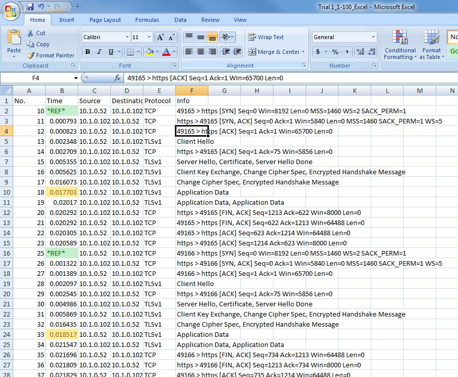
118
Overview. SSL Cryptography Overview CHAPTER 1
 CHAPTER 1 Secure Sockets Layer (SSL) is an application-level protocol that provides encryption technology for the Internet. SSL ensures the secure transmission of data between a client and a server through
CSCE 715: Network Systems Security
 CSCE 715: Network Systems Security Chin-Tser Huang huangct@cse.sc.edu University of South Carolina Web Security Web is now widely used by business, government, and individuals But Internet and Web are
Cryptography (Overview)
") Cryptography (Overview) Some history Caesar cipher, rot13 substitution ciphers, etc. Enigma (Turing) Modern secret key cryptography DES, AES Public key cryptography RSA, digital signatures Cryptography
Cryptography (Overview) Some history Caesar cipher, rot13 substitution ciphers, etc. Enigma (Turing) Modern secret key cryptography DES, AES Public key cryptography RSA, digital signatures Cryptography
Lecture 9a: Secure Sockets Layer (SSL) March, 2004
 March, 2004") Internet and Intranet Protocols and Applications Lecture 9a: Secure Sockets Layer (SSL) March, 2004 Arthur Goldberg Computer Science Department New York University artg@cs.nyu.edu Security Achieved by
Internet and Intranet Protocols and Applications Lecture 9a: Secure Sockets Layer (SSL) March, 2004 Arthur Goldberg Computer Science Department New York University artg@cs.nyu.edu Security Achieved by
TLS. RFC2246: The TLS Protocol. (c) A. Mariën -
 A. Mariën -") TLS RFC2246: The TLS Protocol What does it achieve? Confidentiality and integrity of the communication Server authentication Eventually: client authentication What is does not do Protect the server Protect
TLS RFC2246: The TLS Protocol What does it achieve? Confidentiality and integrity of the communication Server authentication Eventually: client authentication What is does not do Protect the server Protect
Chapter 4: Securing TCP connections
 Managing and Securing Computer Networks Guy Leduc Chapter 5: Securing TCP connections Computer Networking: A Top Down Approach, 6 th edition. Jim Kurose, Keith Ross Addison-Wesley, March 2012. (section
(2½ hours) Total Marks: 75
 Total Marks: 75") (2½ hours) Total Marks: 75 N. B.: (1) All questions are compulsory. (2) Makesuitable assumptions wherever necessary and state the assumptions made. (3) Answers to the same question must be written together.
(2½ hours) Total Marks: 75 N. B.: (1) All questions are compulsory. (2) Makesuitable assumptions wherever necessary and state the assumptions made. (3) Answers to the same question must be written together.
E-commerce security: SSL/TLS, SET and others. 4.1
 E-commerce security: SSL/TLS, SET and others. 4.1 1 Electronic payment systems Purpose: facilitate the safe and secure transfer of monetary value electronically between multiple parties Participating parties:
Protocols, Technologies and Standards Secure network protocols for the OSI stack P2.1 WLAN Security WPA, WPA2, IEEE i, IEEE 802.1X P2.
 P2 Protocols, Technologies and Standards Secure network protocols for the OSI stack P2.1 WLAN Security WPA, WPA2, IEEE 802.11i, IEEE 802.1X P2.2 IP Security IPsec transport mode (host-to-host), ESP and
CSE 3461/5461: Introduction to Computer Networking and Internet Technologies. Network Security. Presentation L
 CS 3461/5461: Introduction to Computer Networking and Internet Technologies Network Security Study: 21.1 21.5 Kannan Srinivasan 11-27-2012 Security Attacks, Services and Mechanisms Security Attack: Any
Transport Layer Security
 CEN585 Computer and Network Security Transport Layer Security Dr. Mostafa Dahshan Department of Computer Engineering College of Computer and Information Sciences King Saud University mdahshan@ksu.edu.sa
The World Wide Web is widely used by businesses, government agencies, and many individuals. But the Internet and the Web are extremely vulnerable to
 1 The World Wide Web is widely used by businesses, government agencies, and many individuals. But the Internet and the Web are extremely vulnerable to compromises of various sorts, with a range of threats
CS 393 Network Security. Nasir Memon Polytechnic University Module 12 SSL
 CS 393 Network Security Nasir Memon Polytechnic University Module 12 SSL Course Logistics HW 4 due today. HW 5 will be posted later today. Due in a week. Group homework. DoD Scholarships? NSF Scholarships?
CS 356 Internet Security Protocols. Fall 2013
 CS 356 Internet Security Protocols Fall 2013 Review Chapter 1: Basic Concepts and Terminology Chapter 2: Basic Cryptographic Tools Chapter 3 User Authentication Chapter 4 Access Control Lists Chapter 5
Overview of SSL/TLS. Luke Anderson. 12 th May University Of Sydney.
 Overview of SSL/TLS Luke Anderson luke@lukeanderson.com.au 12 th May 2017 University Of Sydney Overview 1. Introduction 1.1 Raw HTTP 1.2 Introducing SSL/TLS 2. Certificates 3. Attacks Introduction Raw
Cristina Nita-Rotaru. CS355: Cryptography. Lecture 17: X509. PGP. Authentication protocols. Key establishment.
 CS355: Cryptography Lecture 17: X509. PGP. Authentication protocols. Key establishment. Public Keys and Trust Public Key:P A Secret key: S A Public Key:P B Secret key: S B How are public keys stored How
Encryption. INST 346, Section 0201 April 3, 2018
 Encryption INST 346, Section 0201 April 3, 2018 Goals for Today Symmetric Key Encryption Public Key Encryption Certificate Authorities Secure Sockets Layer Simple encryption scheme substitution cipher:
Security Protocols and Infrastructures. Winter Term 2010/2011
 Winter Term 2010/2011 Chapter 4: Transport Layer Security Protocol Contents Overview Record Protocol Cipher Suites in TLS 1.2 Handshaking Protocols Final Discussion 2 Contents Overview Record Protocol
Lecture Nov. 21 st 2006 Dan Wendlandt ISP D ISP B ISP C ISP A. Bob. Alice. Denial-of-Service. Password Cracking. Traffic.
 15-441 Lecture Nov. 21 st 2006 Dan Wendlandt Worms & Viruses Phishing End-host impersonation Denial-of-Service Route Hijacks Traffic modification Spyware Trojan Horse Password Cracking IP Spoofing DNS
MTAT Applied Cryptography
 MTAT.07.017 Applied Cryptography Transport Layer Security (TLS) Advanced Features University of Tartu Spring 2016 1 / 16 Client Server Authenticated TLS ClientHello ServerHello, Certificate, ServerHelloDone
Secure Socket Layer. Security Threat Classifications
 Secure Socket Layer 1 Security Threat Classifications One way to classify Web security threats in terms of the type of the threat: Passive threats Active threats Another way to classify Web security threats
WAP Security. Helsinki University of Technology S Security of Communication Protocols
 WAP Security Helsinki University of Technology S-38.153 Security of Communication Protocols Mikko.Kerava@iki.fi 15.4.2003 Contents 1. Introduction to WAP 2. Wireless Transport Layer Security 3. Other WAP
Security Protocols and Infrastructures. Winter Term 2015/2016
 Winter Term 2015/2016 Nicolas Buchmann (Harald Baier) Chapter 8: Transport Layer Security Protocol Key Questions Application context of TLS? Which security goals shall be achieved? Approaches? 2 Contents
Computer Security. 10r. Recitation assignment & concept review. Paul Krzyzanowski. Rutgers University. Spring 2018
 Computer Security 10r. Recitation assignment & concept review Paul Krzyzanowski Rutgers University Spring 2018 April 3, 2018 CS 419 2018 Paul Krzyzanowski 1 1. What is a necessary condition for perfect
Public-key Cryptography: Theory and Practice
 Public-key Cryptography Theory and Practice Department of Computer Science and Engineering Indian Institute of Technology Kharagpur Chapter 1: Overview What is Cryptography? Cryptography is the study of
Kurose & Ross, Chapters (5 th ed.)
") Kurose & Ross, Chapters 8.2-8.3 (5 th ed.) Slides adapted from: J. Kurose & K. Ross \ Computer Networking: A Top Down Approach (5 th ed.) Addison-Wesley, April 2009. Copyright 1996-2010, J.F Kurose and
Kurose & Ross, Chapters 8.2-8.3 (5 th ed.) Slides adapted from: J. Kurose & K. Ross \ Computer Networking: A Top Down Approach (5 th ed.) Addison-Wesley, April 2009. Copyright 1996-2010, J.F Kurose and
Internet security and privacy
 Internet security and privacy SSL/TLS 1 Application layer App. TCP/UDP IP L2 L1 2 Application layer App. SSL/TLS TCP/UDP IP L2 L1 3 History of SSL/TLS Originally, SSL Secure Socket Layer, was developed
L13. Reviews. Rocky K. C. Chang, April 10, 2015
 L13. Reviews Rocky K. C. Chang, April 10, 2015 1 Foci of this course Understand the 3 fundamental cryptographic functions and how they are used in network security. Understand the main elements in securing
Chapter 8 Web Security
 Chapter 8 Web Security Web security includes three parts: security of server, security of client, and network traffic security between a browser and a server. Security of server and security of client
Chapter 9: Key Management
 Chapter 9: Key Management Session and Interchange Keys Key Exchange Cryptographic Key Infrastructure Storing and Revoking Keys Digital Signatures Slide #9-1 Overview Key exchange Session vs. interchange
Universität Hamburg. SSL & Company. Fachbereich Informatik SVS Sicherheit in Verteilten Systemen. Security in TCP/IP. UH, FB Inf, SVS, 18-Okt-04 2
 Universität Hamburg SSL & Company Fachbereich Informatik SVS Sicherheit in Verteilten Systemen Security in TCP/IP UH, FB Inf, SVS, 18-Okt-04 2 SSL/TLS Overview SSL/TLS provides security at TCP layer. Uses
Public Key Algorithms
 CSE597B: Special Topics in Network and Systems Security Public Key Cryptography Instructor: Sencun Zhu The Pennsylvania State University Public Key Algorithms Public key algorithms RSA: encryption and
Lecture 1 Applied Cryptography (Part 1)
") Lecture 1 Applied Cryptography (Part 1) Patrick P. C. Lee Tsinghua Summer Course 2010 1-1 Roadmap Introduction to Security Introduction to Cryptography Symmetric key cryptography Hash and message authentication
Lecture 1 Applied Cryptography (Part 1) Patrick P. C. Lee Tsinghua Summer Course 2010 1-1 Roadmap Introduction to Security Introduction to Cryptography Symmetric key cryptography Hash and message authentication
Network Security: TLS/SSL. Tuomas Aura T Network security Aalto University, Nov-Dec 2010
 Network Security: TLS/SSL Tuomas Aura T-110.5240 Network security Aalto University, Nov-Dec 2010 Outline 1. Diffie-Hellman 2. Key exchange using public-key encryption 3. Goals of authenticated key exchange
IBM i Version 7.2. Security Digital Certificate Manager IBM
 IBM i Version 7.2 Security Digital Certificate Manager IBM IBM i Version 7.2 Security Digital Certificate Manager IBM Note Before using this information and the product it supports, read the information
Key Management. Digital signatures: classical and public key Classic and Public Key exchange. Handwritten Signature
 Key Management Digital signatures: classical and public key Classic and Public Key exchange 1 Handwritten Signature Used everyday in a letter, on a check, sign a contract A signature on a signed paper
Network Security: TLS/SSL. Tuomas Aura T Network security Aalto University, Nov-Dec 2014
 Network Security: TLS/SSL Tuomas Aura T-110.5241 Network security Aalto University, Nov-Dec 2014 Outline 1. Diffie-Hellman key exchange (recall from earlier) 2. Key exchange using public-key encryption
Lecture 2 Applied Cryptography (Part 2)
") Lecture 2 Applied Cryptography (Part 2) Patrick P. C. Lee Tsinghua Summer Course 2010 2-1 Roadmap Number theory Public key cryptography RSA Diffie-Hellman DSA Certificates Tsinghua Summer Course 2010 2-2
Lecture 2 Applied Cryptography (Part 2) Patrick P. C. Lee Tsinghua Summer Course 2010 2-1 Roadmap Number theory Public key cryptography RSA Diffie-Hellman DSA Certificates Tsinghua Summer Course 2010 2-2
Digital Certificates Demystified
 Digital Certificates Demystified Ross Cooper, CISSP IBM Corporation RACF/PKI Development Poughkeepsie, NY Email: rdc@us.ibm.com August 9 th, 2012 Session 11622 Agenda Cryptography What are Digital Certificates
CS Computer Networks 1: Authentication
 CS 3251- Computer Networks 1: Authentication Professor Patrick Traynor 4/14/11 Lecture 25 Announcements Homework 3 is due next class. Submit via T-Square or in person. Project 3 has been graded. Scores
SSL/TLS & 3D Secure. CS 470 Introduction to Applied Cryptography. Ali Aydın Selçuk. CS470, A.A.Selçuk SSL/TLS & 3DSec 1
 SSL/TLS & 3D Secure CS 470 Introduction to Applied Cryptography Ali Aydın Selçuk CS470, A.A.Selçuk SSL/TLS & 3DSec 1 SSLv2 Brief History of SSL/TLS Released in 1995 with Netscape 1.1 Key generation algorithm
Crypto meets Web Security: Certificates and SSL/TLS
 CSE 484 / CSE M 584: Computer Security and Privacy Crypto meets Web Security: Certificates and SSL/TLS Spring 2016 Franziska (Franzi) Roesner franzi@cs.washington.edu Thanks to Dan Boneh, Dieter Gollmann,
Introduction to SSL. Copyright 2005 by Sericon Technology Inc.
 Introduction to SSL The cornerstone of e-commerce is a Web site s ability to prevent eavesdropping on data transmitted to and from its site. Without this, consumers would justifiably be afraid to enter
Transport Layer Security
 Cryptography and Security in Communication Networks Transport Layer Security ETTI - Master - Advanced Wireless Telecommunications Secure channels Secure data delivery on insecure networks Create a secure
MTAT Applied Cryptography
 MTAT.07.017 Applied Cryptography Transport Layer Security (TLS) University of Tartu Spring 2017 1 / 22 Transport Layer Security TLS is cryptographic protocol that provides communication security over the
Computer Security. 08r. Pre-exam 2 Last-minute Review Cryptography. Paul Krzyzanowski. Rutgers University. Spring 2018
 Computer Security 08r. Pre-exam 2 Last-minute Review Cryptography Paul Krzyzanowski Rutgers University Spring 2018 March 26, 2018 CS 419 2018 Paul Krzyzanowski 1 Cryptographic Systems March 26, 2018 CS
Transport Level Security
 2 Transport Level Security : Security and Cryptography Sirindhorn International Institute of Technology Thammasat University Prepared by Steven Gordon on 28 October 2013 css322y13s2l12, Steve/Courses/2013/s2/css322/lectures/transport.tex,
Datasäkerhetsmetoder föreläsning 7
 Datasäkerhetsmetoder föreläsning 7 Nyckelhantering Jan-Åke Larsson Cryptography A security tool, not a general solution Cryptography usually converts a communication security problem into a key management
Cryptography and Network Security Chapter 14
 Cryptography and Network Security Chapter 14 Fifth Edition by William Stallings Lecture slides by Lawrie Brown Chapter 14 Key Management and Distribution No Singhalese, whether man or woman, would venture
Security. Communication security. System Security
 Security Communication security security of data channel typical assumption: adversary has access to the physical link over which data is transmitted cryptographic separation is necessary System Security
Security Protocols and Infrastructures
 Security Protocols and Infrastructures Dr. Michael Schneider michael.schneider@h-da.de Chapter 8: The Transport Layer Security Protocol (TLS) December 4, 2017 h_da WS2017/18 Dr. Michael Schneider 1 1 Overview
Modern cryptography 2. CSCI 470: Web Science Keith Vertanen
 Modern cryptography 2 CSCI 470: Web Science Keith Vertanen Modern cryptography Overview Asymmetric cryptography Diffie-Hellman key exchange (last time) Pubic key: RSA Pretty Good Privacy (PGP) Digital
INF3510 Information Security University of Oslo Spring Lecture 9 Communication Security. Audun Jøsang
 INF3510 Information Security University of Oslo Spring 2011 Lecture 9 Communication Security Audun Jøsang Outline Network security concepts Communication security Perimeter security Protocol architecture
SharkFest 17 Europe. SSL/TLS Decryption. uncovering secrets. Wednesday November 8th, Peter Wu Wireshark Core Developer
 SharkFest 17 Europe SSL/TLS Decryption uncovering secrets Wednesday November 8th, 2017 Peter Wu Wireshark Core Developer peter@lekensteyn.nl 1 About me Wireshark contributor since 2013, core developer
Security Digital Certificate Manager
 System i Security Digital Certificate Manager Version 6 Release 1 System i Security Digital Certificate Manager Version 6 Release 1 Note Before using this information and the product it supports, be sure
ח'/סיון/תשע "א. RSA: getting ready. Public Key Cryptography. Public key cryptography. Public key encryption algorithms
 Public Key Cryptography Kurose & Ross, Chapters 8.28.3 (5 th ed.) Slides adapted from: J. Kurose & K. Ross \ Computer Networking: A Top Down Approach (5 th ed.) AddisonWesley, April 2009. Copyright 19962010,
Cryptography SSL/TLS. Network Security Workshop. 3-5 October 2017 Port Moresby, Papua New Guinea
 Cryptography SSL/TLS Network Security Workshop 3-5 October 2017 Port Moresby, Papua New Guinea 1 History Secure Sockets Layer was developed by Netscape in 1994 as a protocol which permitted persistent
Issues. Separation of. Distributed system security. Security services. Security policies. Security mechanism
 Module 9 - Security Issues Separation of Security policies Precise definition of which entities in the system can take what actions Security mechanism Means of enforcing that policy Distributed system
Cryptography and secure channel. May 17, Networks and Security. Thibault Debatty. Outline. Cryptography. Public-key encryption
 and secure channel May 17, 2018 1 / 45 1 2 3 4 5 2 / 45 Introduction Simplified model for and decryption key decryption key plain text X KE algorithm KD Y = E(KE, X ) decryption ciphertext algorithm X
Computer Networks 1 (Mạng Máy Tính 1) Lectured by: Dr. Phạm Trần Vũ
 Lectured by: Dr. Phạm Trần Vũ") Computer Networks 1 (Mạng Máy Tính 1) Lectured by: Dr. Phạm Trần Vũ Chapter 8 Network Security Computer Networking: A Top Down Approach, 5 th edition. Jim Kurose, Keith Ross Addison-Wesley, April 2009.
Computer Networks 1 (Mạng Máy Tính 1) Lectured by: Dr. Phạm Trần Vũ Chapter 8 Network Security Computer Networking: A Top Down Approach, 5 th edition. Jim Kurose, Keith Ross Addison-Wesley, April 2009.
Information Security. message M. fingerprint f = H(M) one-way hash. 4/19/2006 Information Security 1
 one-way hash. 4/19/2006 Information Security 1") Information Security message M one-way hash fingerprint f = H(M) 4/19/2006 Information Security 1 Outline and Reading Digital signatures Definition RSA signature and verification One-way hash functions
Information Security message M one-way hash fingerprint f = H(M) 4/19/2006 Information Security 1 Outline and Reading Digital signatures Definition RSA signature and verification One-way hash functions
White Paper for Wacom: Cryptography in the STU-541 Tablet
 Issue 0.2 Commercial In Confidence 1 White Paper for Wacom: Cryptography in the STU-541 Tablet Matthew Dodd matthew@cryptocraft.co.uk Cryptocraft Ltd. Chapel Cottage Broadchalke Salisbury Wiltshire SP5
Verteilte Systeme (Distributed Systems)
") Verteilte Systeme (Distributed Systems) Lorenz Froihofer l.froihofer@infosys.tuwien.ac.at http://www.infosys.tuwien.ac.at/teaching/courses/ VerteilteSysteme/ Security Threats, mechanisms, design issues
Verteilte Systeme (Distributed Systems) Lorenz Froihofer l.froihofer@infosys.tuwien.ac.at http://www.infosys.tuwien.ac.at/teaching/courses/ VerteilteSysteme/ Security Threats, mechanisms, design issues
Configuring SSL. SSL Overview CHAPTER
 7 CHAPTER This topic describes the steps required to configure your ACE appliance as a virtual Secure Sockets Layer (SSL) server for SSL initiation or termination. The topics included in this section are:
Cryptography & Key Exchange Protocols. Faculty of Computer Science & Engineering HCMC University of Technology
 Cryptography & Key Exchange Protocols Faculty of Computer Science & Engineering HCMC University of Technology Outline 1 Cryptography-related concepts 2 3 4 5 6 7 Key channel for symmetric cryptosystems
Information Security CS 526
 Information Security CS 526 Topic 14: Key Distribution & Agreement, Secure Communication Topic 14: Secure Communication 1 Readings for This Lecture On Wikipedia Needham-Schroeder protocol (only the symmetric
From Coulouris, Dollimore and Kindberg Distributed Systems: Concepts and Design. Edition 4 Pearson Education 2005
 Chapter 7: Security From Coulouris, Dollimore and Kindberg Distributed Systems: Concepts and Design Edition 4 Introduction Security policies Provide for the sharing of resources within specified limits
CSC 774 Network Security
 CSC 774 Network Security Topic 2. Review of Cryptographic Techniques CSC 774 Dr. Peng Ning 1 Outline Encryption/Decryption Digital signatures Hash functions Pseudo random functions Key exchange/agreement/distribution
Configuring SSL CHAPTER
 7 CHAPTER This chapter describes the steps required to configure your ACE appliance as a virtual Secure Sockets Layer (SSL) server for SSL initiation or termination. The topics included in this section
Configuring SSL. SSL Overview CHAPTER
 CHAPTER 8 Date: 4/23/09 This topic describes the steps required to configure your ACE (both the ACE module and the ACE appliance) as a virtual Secure Sockets Layer (SSL) server for SSL initiation or termination.
Protecting Information Assets - Week 11 - Cryptography, Public Key Encryption and Digital Signatures. MIS 5206 Protecting Information Assets
 Protecting Information Assets - Week 11 - Cryptography, Public Key Encryption and Digital Signatures MIS5206 Week 11 Identity and Access Control Week 10 continued Cryptography, Public Key Encryption and
CSC/ECE 774 Advanced Network Security
 Computer Science CSC/ECE 774 Advanced Network Security Topic 2. Network Security Primitives CSC/ECE 774 Dr. Peng Ning 1 Outline Absolute basics Encryption/Decryption; Digital signatures; D-H key exchange;
Data Security and Privacy. Topic 14: Authentication and Key Establishment
 Data Security and Privacy Topic 14: Authentication and Key Establishment 1 Announcements Mid-term Exam Tuesday March 6, during class 2 Need for Key Establishment Encrypt K (M) C = Encrypt K (M) M = Decrypt
David Wetherall, with some slides from Radia Perlman s security lectures.
 David Wetherall, with some slides from Radia Perlman s security lectures. djw@cs.washington.edu Networks are shared: Want to secure communication between legitimate participants from others with (passive
Cryptographic Checksums
 Cryptographic Checksums Mathematical function to generate a set of k bits from a set of n bits (where k n). k is smaller then n except in unusual circumstances Example: ASCII parity bit ASCII has 7 bits;
Lecture Notes 14 : Public-Key Infrastructure
 6.857 Computer and Network Security October 24, 2002 Lecture Notes 14 : Public-Key Infrastructure Lecturer: Ron Rivest Scribe: Armour/Johann-Berkel/Owsley/Quealy [These notes come from Fall 2001. These
Authentication CHAPTER 17
 Authentication CHAPTER 17 Authentication Authentication is the process by which you decide that someone is who they say they are and therefore permitted to access the requested resources. getting entrance
Understanding Traffic Decryption
 The following topics provide an overview of SSL inspection, describe the prerequisites for SSL inspection configuration, and detail deployment scenarios. Traffic Decryption Overview, page 1 SSL Handshake
CSCE 715: Network Systems Security
 CSCE 715: Network Systems Security Chin-Tser Huang huangct@cse.sc.edu University of South Carolina Next Topic in Cryptographic Tools Symmetric key encryption Asymmetric key encryption Hash functions and
Displaying SSL Configuration Information and Statistics
 CHAPTER 7 Displaying SSL Configuration Information and Statistics This chapter describes the show commands available for displaying CSS SSL configuration information and statistics and an explanation of
CIS 5373 Systems Security
 CIS 5373 Systems Security Topic 4.3: Network Security SSL/TLS Endadul Hoque Slide Acknowledgment Contents are based on slides from Cristina Nita-Rotaru (Northeastern) Analysis of the HTTPS Certificate
key distribution requirements for public key algorithms asymmetric (or public) key algorithms
 key algorithms") topics: cis3.2 electronic commerce 24 april 2006 lecture # 22 internet security (part 2) finish from last time: symmetric (single key) and asymmetric (public key) methods different cryptographic systems
topics: cis3.2 electronic commerce 24 april 2006 lecture # 22 internet security (part 2) finish from last time: symmetric (single key) and asymmetric (public key) methods different cryptographic systems
Securing Internet Communication: TLS
 Securing Internet Communication: TLS CS 161: Computer Security Prof. David Wagner March 11, 2016 Today s Lecture Applying crypto technology in practice Two simple abstractions cover 80% of the use cases
Auth. Key Exchange. Dan Boneh
 Auth. Key Exchange Review: key exchange Alice and want to generate a secret key Saw key exchange secure against eavesdropping Alice k eavesdropper?? k This lecture: Authenticated Key Exchange (AKE) key
CPSC 467b: Cryptography and Computer Security
 CPSC 467b: Cryptography and Computer Security Michael J. Fischer Lecture 24 April 16, 2012 CPSC 467b, Lecture 24 1/33 Kerberos Secure Shell (SSH) Transport Layer Security (TLS) Digital Rights Management
Security issues: Encryption algorithms. Threats Methods of attack. Secret-key Public-key Hybrid protocols. CS550: Distributed OS.
 Security issues: Threats Methods of attack Encryption algorithms Secret-key Public-key Hybrid protocols Lecture 15 Page 2 1965-75 1975-89 1990-99 Current Platforms Multi-user timesharing computers Distributed
IBM. Security Digital Certificate Manager. IBM i 7.1
 IBM IBM i Security Digital Certificate Manager 7.1 IBM IBM i Security Digital Certificate Manager 7.1 Note Before using this information and the product it supports, be sure to read the information in
Principles of Information Security, Fourth Edition. Chapter 8 Cryptography
 Principles of Information Security, Fourth Edition Chapter 8 Cryptography Learning Objectives Upon completion of this material, you should be able to: Chronicle the most significant events and discoveries
Proving who you are. Passwords and TLS
 Proving who you are Passwords and TLS Basic, fundamental problem Client ( user ) How do you prove to someone that you are who you claim to be? Any system with access control must solve this Users and servers
14. Internet Security (J. Kurose)
") 14. Internet Security (J. Kurose) 1 Network security Foundations: what is security? cryptography authentication message integrity key distribution and certification Security in practice: application layer:
14. Internet Security (J. Kurose) 1 Network security Foundations: what is security? cryptography authentication message integrity key distribution and certification Security in practice: application layer:
Transport Layer Security
 Transport Layer Security TRANSPORT LAYER SECURITY PERFORMANCE TESTING OVERVIEW Transport Layer Security (TLS) and its predecessor Secure Sockets Layer (SSL), are the most popular cryptographic protocols
TLS Extensions Project IMT Network Security Spring 2004
 TLS Extensions Project IMT4101 - Network Security Spring 2004 Ole Martin Dahl [ole.dahl@hig.no] Torkjel Søndrol [torkjel.soendrol@hig.no] Fredrik Skarderud [fredrik.skarderud@hig.no] Ole Kasper Olsen [ole.olsen@hig.no]
Cryptographic Concepts
 Outline Identify the different types of cryptography Learn about current cryptographic methods Chapter #23: Cryptography Understand how cryptography is applied for security Given a scenario, utilize general
CS 161 Computer Security
 Raluca Ada Popa Spring 2018 CS 161 Computer Security Discussion 6 Week of February 26, 2018 Question 1 TLS threats (10 min) An attacker is trying to attack the company Boogle and its users. Assume that
CSC 5930/9010 Modern Cryptography: Public-Key Infrastructure
 CSC 5930/9010 Modern Cryptography: Public-Key Infrastructure Professor Henry Carter Fall 2018 Recap Digital signatures provide message authenticity and integrity in the public-key setting As well as public
TLSnotary - a mechanism for independently audited https sessions
 TLSnotary - a mechanism for independently audited https sessions September 10, 2014 1 Abstract TLSnotary allows a client to provide evidence to a third party auditor that certain web traffic occurred between
Chapter 7. WEB Security. Dr. BHARGAVI H. GOSWAMI Department of Computer Science Christ University
 Chapter 7 WEB Security Dr. BHARGAVI H. GOSWAMI Department of Computer Science Christ University +91 9426669020 bhargavigoswami@gmail.com Topic List 1. Web Security Considerations 2. Secure Socket Layer
KALASALINGAM UNIVERSITY
 KALASALINGAM UNIVERSITY (Kalasalingam Academy of Research and Education) DEPARTMENT OF COMPUTER SCIENCE AND ENGINEERING CLASS NOTES CRYPTOGRAPHY AND NETWOTK SECURITY (CSE 405) Prepared by M.RAJA AP/CSE
Cryptography III. Public-Key Cryptography Digital Signatures. 2/1/18 Cryptography III
 Cryptography III Public-Key Cryptography Digital Signatures 2/1/18 Cryptography III 1 Public Key Cryptography 2/1/18 Cryptography III 2 Key pair Public key: shared with everyone Secret key: kept secret,
9/30/2016. Cryptography Basics. Outline. Encryption/Decryption. Cryptanalysis. Caesar Cipher. Mono-Alphabetic Ciphers
 Cryptography Basics IT443 Network Security Administration Slides courtesy of Bo Sheng Basic concepts in cryptography systems Secret cryptography Public cryptography 1 2 Encryption/Decryption Cryptanalysis