MSP 432. A compact starter kit with your favorite microcontroller and a socket for click add-on boards. New ideas are just a click away.
|
|
|
- Stephen Nash
- 5 years ago
- Views:
Transcription


1 MSP 432 A compact starter kit with your favorite microcontroller and a socket for click add-on boards. New ideas are just a click away.
2 TO OUR VALUED CUSTOMERS I want to express my thanks to you for being interested in our products and for having confidence in MikroElektronika. The primary aim of our company is to design and produce high quality electronic products and to constantly improve the performance thereof in order to better suit your needs. Nebojsa Matic General Manager The PIC and Windows logos and product names are trademarks of Microchip Technology and Microsoft in the U.S.A. and other countries. Page 2
3 Table of contents. What is STM32 M4 clicker? 4 2. Power supply 7 3. STM32F45RG microcontroller 9 Key microcontroller features 9 4. Programming the microcontroller 0 Programming with mikrobootloader step Connecting STM32 M4 clicker step 2 Browsing for.hex file 2 step 3 Selecting.HEX file 2 step 4 Uploading.HEX file 3 step 5 Finish upload 4 Programming with mikroprog programmer 5 mikroprog Suite for ARM software 6 5. Buttons and LEDs 8 6. click boards are plug and play! Dimensions 22 Page 3

4 . What is MSP432 clicker? Micro USB connector Voltage Regulator khz Crystal 06 SWO/Jtag programmer connector 03 Power Indication LED 9 05 MSP432 MCU 04 GPIO pinout 07 microbus TM socket 03 Reset Button MSP432 clicker is an amazingly compact starter development kit which brings the innovative mikrobus socket to your favorite microcontroller. It features MSP432, a 32- bit ARM Cortex -M4 microcontroller, two indication LEDs, two general purpose buttons, a reset button, a USB Micro connector and a single mikrobus socket. A JTAG connector and pads for interfacing with external electronics are provided as well. The mikrobus connector consists of two x8 female headers with SPI, I 2 C, UART, RST, PWM, Analog and Interrupt lines as well as 3.3V, 5V and power lines. MSP432 clicker board can be powered over a USB cable. Push Buttons 0 0 LEDs Push Buttons Page 4
5 Page 5 T2 T AN RST CS SCK MISO MOSI 3.3V PWM INT RX TX SCL SDA 5V MIKROBUS MIKROBUS HOST CONN R8 k R7 k LD2 LD JTAG_TMS JTAG_TDI JTAG_TDO JTAG_TCK C FP AVCC MCU_RST C9 Y kHz C0 C5 C6 C7 R2 0R R 47k MCU_RST MCU_RST C4 nf R 9k C 2pF C2 2pF OSC 2 OSC2 3 4 Y 48MHz C2 2pF C3 2pF AVCC AVCC P8.0_LED P8._LED2 P.0_BUTTON P._BUTTON2 P2.5_PWM P.6_SPI_MOSI P.5_SPI_CLK P.7_SPI_MISO P.4_SPI_CS P5.5_AN0 P5.4_AN P5.3_AN2 P5._AN4 P.2_UART_RX P.3_UART_TX P3.7I2C_SCL P3.6_I2C_SDA JTAG_TDO JTAG_TDI JTAG_TCK JTAG_TMS OSC OSC2 L 0µH C8 VCC-5V P.6_SPI_MOSI P.5_SPI_CLK P.7_SPI_MISO P8.0_LED P8._LED2 P2.5_PWM P3.7I2C_SCL P3.6_I2C_SDA P5.5_AN0 P5.4_AN P5.3_AN2 P.0_BUTTON P._BUTTON P3.3 P3.2 P3. P3.0 PJ.0 AVSS3 P. P.2 P.3 P.4 P5.5 P5.4 P5.3 P4. AVSS PJ. P9. P6.0 P6. P4.0 DCOR AVCC P7.3 P7.2 P7. PJ.5 P7.0 AVCC2 AVSS2 RSTn P.0 P0.3 P9.6 P9.5 P9.4 SWCLK/TCK SWDIO/TMS PJ.4 VCORE P7.6 P2.7 P2.6 P2.5 P2.4 P2.3 P2.2 P5.7 P5.6 P9.0 P8.7 VSW P.7 P.6 P3.5 P9.7 P0.0 P0. P0.2 P7.5 P7.4 P0.5 P0.4 P8.4 P8.5 P5.2 P4.5 P8.2 P8.3 P4.2 P3.6 P4.3 P4.6 PJ.3 P2. P2.0 DVSS P3.4 P3.7 P4.4 P5. PJ.2 P8. P8.0 P7.7 DVCC P.5 P4.7 P5.0 DVSS2 P6.4 P6.2 DVCC2 P9.2 P9.3 P6.3 P6.5 P6.6 P6.7 DVSS3 P8.6 MSP432P40R U T3 TASTER 2-PIN J HM2X5 C24 C2 C23 C HD P3.5_USB_DET P8.2_FTD_RST P6.0_AN5 P6.0_AN5 P5.6_RST P5.6_RST P5.0_SPI_CS P5.0_SPI_CS P2.7_PWM P2.7_PWM P2.4_INT P2.4_INT P3.2_UART_RX P3.3_UART_TX P3.2_UART_RX P3.3_UART_TX P6.4_I2C_SDA P6.5_I2C_SCL P6.4_I2C_SDA P6.5_I2C_SCL P7.5_PWM P7.5_PWM P5._AN4 R9 0k R0 0k R3 0k R4 0k R5 0k R6 0k Figure -2: MSP432 clicker schematic
6 Page 6 VCC-USB USB-D_P USB-D_N USB-D_P USB-D_N D_N D_P C20 R22 M R6 27 R5 27 VCCIO RXD CTS CB2 RST VCC CB CB0 RTS TXD CB3 DP DM 3V3 PAD U3 FT230x FP2 C7 0000pF R3 8.2k R2 4.7k FP3 C9 µf C8 VCC-USB VCC-5V R8 470 PWR LED GREEN USB_RX USB_TX R R24 k 2 3 IN OUT 5 4 EN ADJ U2 SPX389M5 R4 47k R7 27k R20 k C3 0 F R2 0k C5 0µF VCC-USB VCC-USB P.2_UART_RX P.3_UART_TX ID D+ D- VBUS CN LF P3.5_USB_DET P8.2_FTD_RST C4 0.0µF C6 0.0µF R25 0k Figure -3: MSP432 clicker schematic


7 2. Power supply Figure 2-: Connecting USB power supply through CN connector When the board is powered up the power indication LED will be automatically turned on. The USB connection can provide up to 500mA of current which is more than enough for the operation of all on-board and additional modules. Page 7
8 VCC-USB VCC-USB C3 0 F C4 0.0µF R2 0k U2 2 IN OUT 3 EN ADJ SPX389M5 5 4 R4 47k R7 27k R20 k C5 0µF C6 0.0µF PWR LED GREEN R8 470 VCC-USB VCC-5V FP3 C8 C9 µf Figure 2-2: Power supply schematic Page 8

9 3. MSP432 microcontroller The MSP432 clicker development tool comes with the MSP432 microcontroller. This 32-bit high performance microcontroller is rich with on-chip peripherals and features 024KB of Flash and 92KB of SRAM. It has integrated full speed USB 2.0. support. Key microcontroller features - Up to 68 MHz operation - 32-bit ARM Cortex -M4 architecture - 024KB of Flash memory - 92KB SRAM - 64 pin LQFP - 3x 6 ch, 2-bit ADC - USB 2.0, UART, RTC, SPI, I 2 C, etc. Page 9


10 4. Programming the microcontroller Figure 4-: MSP432 microcontroller The microcontroller can be programmed in two ways: 0 02 Using USB HID mikrobootloader, Using external mikroprog for MSP432 programmer. Page 0
 which can be downloaded from: https://download.mikroe.")
11 Programming with mikrobootloader You can program the microcontroller with a bootloader which is preprogrammed by default. To transfer.hex file from a PC to MCU you need bootloader software (mikrobootloader USB HID) which can be downloaded from: zipzip After the mikrobootloader software is downloaded, unzip it to desired location and start it. step Connecting MSP432 clicker 0 Figure 4-2: USB HID mikrobootloader window 0 To start, connect the USB cable, or if already connected press the Reset button on your MSP432. Click the Connect button within 5s to enter the bootloader mode, otherwise existing microcontroller program will execute. Page

12 step 2 Browsing for.hex file step 3 Selecting.HEX file Figure 4-3: Browse for HEX Figure 4-4: Selecting HEX 0 Click the Browse for HEX button and from a 0 Select.HEX file using open dialog window. pop-up window (Figure 3.4) choose the.hex file which will be uploaded to MCU memory. 02 Click the Open button. Page 2


13 step 4 Uploading.HEX file 0 0 Figure 4-5: Begin uploading Figure 4-6: Progress bar 0 To start.hex file bootloading click the 0 Begin uploading button. Progress bar enables you to monitor.hex file uploading. Page 3


14 step 5 Finish upload 0 Figure 4-7: Restarting MCU Figure 4-8: mikrobootloader ready for next job 0 Click OK button after the uploading process is finished. 02 Press Reset button on MSP432 clicker board and wait for 5 seconds. Your program will run automatically. Page 4


15 Programming with mikroprog programmer Figure 4-9: mikroprog connector The microcontroller can be programmed with external mikroprog for MSP432 programmer and mikroprog Suite for ARM software. The external programmer is connected to the development system via 2x5 JTAG connector soldered on the CN2 connector pads, Figure 4-9. mikroprog is a fast USB 2.0 programmer with hardware debugger support. Page 5

16 mikroprog Suite for ARM software On-board mikroprog programmer requires special programming software called mikroprog Suite for ARM. This software is used for programming of all supported microcontroller families with ARM Cortex -M3 and Cortex -M4 cores. The software has an intuitive interface and SingleClick programming technology. To begin, first locate the installation archive on the link bellow: After downloading, extract the package and double click the executable setup file, to start installation. Quick guide 0 Click the Detect MCU button in order to recognize the device ID. 02 Click the Read button to read the entire microcontroller memory. You can click the Save button to save it to the target HEX file If you want to write the HEX file into the microcontroller, first make sure to load the target HEX file using the Load button. Then click the Write button to begin programming. Click the Erase button to clear the microcontroller memory. Figure 4-0: mikroprog Suite for ARM window Page 6
17 Page 7 Page 7 Before attaching the programming connector, you have to solder the provided 2x5 male header to the JTAG (CN2) pads. Figure 4-3: mikroprog connection schematic NOTE C9 Y kHz C0 C5 C6 C7 R2 0R R 47k MCU_RST MCU_RST C4 nf R 9k C 2pF C2 2pF OSC 2 OSC2 3 4 Y 48MHz C2 2pF C3 2pF AVCC AVCC P8.0_LED P8._LED2 P.0_BUTTON P._BUTTON2 P2.5_PWM P.6_SPI_MOSI P.5_SPI_CLK P.7_SPI_MISO P.4_SPI_CS P5.5_AN0 P5.4_AN P5.3_AN2 P5._AN4 P.2_UART_RX P.3_UART_TX P3.7I2C_SCL P3.6_I2C_SDA JTAG_TDO JTAG_TDI JTAG_TCK JTAG_TMS OSC OSC2 L 0µH C P3.3 P3.2 P3. P3.0 PJ.0 AVSS3 P. P.2 P.3 P.4 P5.5 P5.4 P5.3 P4. AVSS PJ. P9. P6.0 P6. P4.0 DCOR AVCC P7.3 P7.2 P7. PJ.5 P7.0 AVCC2 AVSS2 RSTn P.0 P0.3 P9.6 P9.5 P9.4 SWCLK/TCK SWDIO/TMS PJ.4 VCORE P7.6 P2.7 P2.6 P2.5 P2.4 P2.3 P2.2 P5.7 P5.6 P9.0 P8.7 VSW P.7 P.6 P3.5 P9.7 P0.0 P0. P0.2 P7.5 P7.4 P0.5 P0.4 P8.4 P8.5 P5.2 P4.5 P8.2 P8.3 P4.2 P3.6 P4.3 P4.6 PJ.3 P2. P2.0 DVSS P3.4 P3.7 P4.4 P5. PJ.2 P8. P8.0 P7.7 DVCC P.5 P4.7 P5.0 DVSS2 P6.4 P6.2 DVCC2 P9.2 P9.3 P6.3 P6.5 P6.6 P6.7 DVSS3 P8.6 MSP432P40R U T3 TASTER 2-PIN C24 C2 C23 C22 P3.5_USB_DET P8.2_FTD_RST P6.0_AN5 P5.6_RST P5.6_RST P5.0_SPI_CS P5.0_SPI_CS P2.7_PWM P2.4_INT P3.2_UART_RX P3.3_UART_TX P6.4_I2C_SDA P6.5_I2C_SCL P7.5_PWM R9 0k R


.")
18 5. Buttons and LEDs Figure 5-: Two buttons, two LEDs and a reset button The board also contains a 0 reset button and a pair of 02 buttons and 03 LEDs. Each of these additional peripherals are located in the bottom area of the board. Reset button is used to manually reset the microcontroller. Pressing the reset button will generate a low voltage level on microcontroller s reset pin. LEDs can be used for visual indication of the logic state on two pins (P6.0 and P6.). An active LED indicates that a logic high () is present on the pin. Pressing any of these buttons can change the logic state of the microcontroller pins (P.0 and P.) from logic high () to logic low (0). Page 8
19 Page 9 Figure 5-2: Other modules connection schematic T2 T AN RST CS SCK MISO MOSI 3.3V PWM INT RX TX SCL SDA 5V MIKROBUS MIKROBUS HOST CONN R8 k R7 k LD2 LD C9 Y kHz C0 C5 C6 C7 R2 0R R 47k MCU_RST MCU_RST C4 nf R 9k C 2pF C2 2pF OSC 2 OSC2 3 4 Y 48MHz C2 2pF C3 2pF AVCC AVCC P8.0_LED P8._LED2 P.0_BUTTON P._BUTTON2 P2.5_PWM P.6_SPI_MOSI P.5_SPI_CLK P.7_SPI_MISO P.4_SPI_CS P5.5_AN0 P5.4_AN P5.3_AN2 P5._AN4 P.2_UART_RX P.3_UART_TX P3.7I2C_SCL P3.6_I2C_SDA JTAG_TDO JTAG_TDI JTAG_TCK JTAG_TMS OSC OSC2 L 0µH C8 VCC-5V P.6_SPI_MOSI P.5_SPI_CLK P.7_SPI_MISO P8.0_LED P8._LED2 P2.5_PWM P3.7I2C_SCL P3.6_I2C_SDA P5.5_AN0 P5.4_AN P5.3_AN2 P.0_BUTTON P._BUTTON P3.3 P3.2 P3. P3.0 PJ.0 AVSS3 P. P.2 P.3 P.4 P5.5 P5.4 P5.3 P4. AVSS PJ. P9. P6.0 P6. P4.0 DCOR AVCC P7.3 P7.2 P7. PJ.5 P7.0 AVCC2 AVSS2 RSTn P.0 P0.3 P9.6 P9.5 P9.4 SWCLK/TCK SWDIO/TMS PJ.4 VCORE P7.6 P2.7 P2.6 P2.5 P2.4 P2.3 P2.2 P5.7 P5.6 P9.0 P8.7 VSW P.7 P.6 P3.5 P9.7 P0.0 P0. P0.2 P7.5 P7.4 P0.5 P0.4 P8.4 P8.5 P5.2 P4.5 P8.2 P8.3 P4.2 P3.6 P4.3 P4.6 PJ.3 P2. P2.0 DVSS P3.4 P3.7 P4.4 P5. PJ.2 P8. P8.0 P7.7 DVCC P.5 P4.7 P5.0 DVSS2 P6.4 P6.2 DVCC2 P9.2 P9.3 P6.3 P6.5 P6.6 P6.7 DVSS3 P8.6 MSP432P40R U T3 TASTER 2-PIN C24 C2 C23 C HD P3.5_USB_DET P8.2_FTD_RST P6.0_AN5 P6.0_AN5 P5.6_RST P5.6_RST P5.0_SPI_CS P5.0_SPI_CS P2.7_PWM P2.7_PWM P2.4_INT P2.4_INT P3.2_UART_RX P3.3_UART_TX P3.2_UART_RX P3.3_UART_TX P6.4_I2C_SDA P6.5_I2C_SCL P6.4_I2C_SDA P6.5_I2C_SCL P7.5_PWM P7.5_PWM P5._AN4 R9 0k R0 0k


20 6. click boards are plug and play! Up to now, MikroElektronika has released more than 270 mikrobus compatible click Boards. On the average, one click board is released per week. It is our intention to provide you with as many add-on boards as possible, so you will be able to expand your development board with additional functionality. Each board comes with a set of working example code. Please visit the click boards webpage for the complete list of currently available boards: Figure 7-: MSP432 clicker driving a GSM click board Page 20


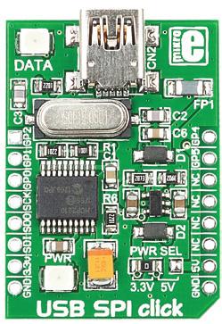
21 RFid click Relay click 8x8 click BarGraph click 7seg click THERMO click FM click Gyro click Page 2 Bluetooth2 click Thunder click USB SPI click EEPROM click LightHz click Pressure click
22 7. Dimensions Legend mm mils Mounting hole size Ø2 Ø Page 22
23 DISCLAIMER All the products owned by MikroElektronika are protected by copyright law and international copyright treaty. Therefore, this manual is to be treated as any other copyright material. No part of this manual, including product and software described herein, may be reproduced, stored in a retrieval system, translated or transmitted in any form or by any means, without the prior written permission of MikroElektronika. The manual PDF edition can be printed for private or local use, but not for distribution. Any modification of this manual is prohibited. MikroElektronika provides this manual as is without warranty of any kind, either expressed or implied, including, but not limited to, the implied warranties or conditions of merchantability or fitness for a particular purpose. MikroElektronika shall assume no responsibility or liability for any errors, omissions and inaccuracies that may appear in this manual. In no event shall MikroElektronika, its directors, officers, employees or distributors be liable for any indirect, specific, incidental or consequential damages (including damages for loss of business profits and business information, business interruption or any other pecuniary loss) arising out of the use of this manual or product, even if MikroElektronika has been advised of the possibility of such damages. MikroElektronika reserves the right to change information contained in this manual at any time without prior notice, if necessary. HIGH RISK ACTIVITIES The products of MikroElektronika are not fault tolerant nor designed, manufactured or intended for use or resale as on line control equipment in hazardous environments requiring fail safe performance, such as in the operation of nuclear facilities, aircraft navigation or communication systems, air traffic control, direct life support machines or weapons systems in which the failure of Software could lead directly to death, personal injury or severe physical or environmental damage ( High Risk Activities ). MikroElektronika and its suppliers specifically disclaim any expressed or implied warranty of fitness for High Risk Activities. TRADEMARKS The MikroElektronika name and logo, mikroc, mikrobasic, mikropascal, Visual TFT, Visual GLCD, mikroprog, Ready, MINI, mikrobus, EasyPIC, EasyAVR, Easy805, click boards and mikromedia are trademarks of MikroElektronika. All other trademarks mentioned herein are property of their respective companies. All other product and corporate names appearing in this manual may or may not be registered trademarks or copyrights of their respective companies, and are only used for identification or explanation and to the owners benefit, with no intent to infringe. Copyright 204 MikroElektronika. All Rights Reserved. Page 23
24 If you want to learn more about our products, please visit our web site at If you are experiencing some problems with any of our products or just need additional information, please place your ticket at If you have any questions, comments or business proposals, do not hesitate to contact us at
MINI-M4. development board for MSP432 MINI ARM
 MINI-M4 development board for MSP432 The whole MSP432 development board fitted in DIP40 form factor, containing powerful MSP432P4R microcontroller. MINI ARM TO OUR VALUED CUSTOMERS I want to express my
CEC1702 clicker. a great idea is just a click away
 a great idea is just a click away CEC1702 clicker A compact development board with a mikrobus socket for click board connectivity and Microchip s CEC1702, a 32-bit ARM Cortex -M4 Processor Core, with strong
PIC32MZ. A compact starter kit with your favorite microcontroller and a mikrobus socket.
 PICMZ A compact starter kit with your favorite microcontroller and a mikrobus socket. TO OUR VALUED CUSTOMERS I want to express my thanks to you for being interested in our products and for having confidence
SHIELD. mikromedia 5. for TIVA ARM
 mikromedia 5 SHIELD for TIVA ARM Expansion board pin-compatible with your mikromedia 5 for TIVA ARM which enables you to easily expand your basic board functionality. TO OUR VALUED CUSTOMERS I want to
A compact starter kit with your favorite microcontroller and a socket for click add-on boards. New ideas are just a click away.
 A compact starter kit with your favorite microcontroller and a socket for click add-on boards. New ideas are just a click away. TO OUR VALUED CUSTOMERS I want to express my thanks to you for being interested
A compact starter kit with your favorite microcontroller and two mikrobus sockets
 dspic33 A compact starter kit with your favorite microcontroller and two mikrobus sockets dspic Page 1 TO OUR VALUED CUSTOMERS I want to express my thanks to you for being interested in our products and
TO OUR VALUED CUSTOMERS
 SmartMP3 Board is ideal for creating mp3 players and adding audio and music features to your prototype devices, even with lower-performance microcontrollers. TO OUR VALUED CUSTOMERS I want to express my
user's guide to Expand development system capabilities by adding 8K EEPROM memory accessory board EEPROM
 user's guide to Expand development system capabilities by adding 8K EEPROM memory accessory board EEPROM TO OUR VALUED CUSTOMERS I want to express my thanks to you for being interested in our products
TO OUR VALUED CUSTOMERS
 mikroprog for STM32 mikroprog is a fast USB programmer with hardware debugger support. Smart engineering allows mikroprog to support all STM32 ARM Cortex -M3 and Cortex -M4 microcontrollers in a single
user's guide to Expand development system capabilities by adding 12bit Digital to Analog Converter 12bit-DAC
 user's guide to Expand development system capabilities by adding 12bit Digital to Analog Converter 12bit-DAC TO OUR VALUED CUSTOMERS I want to express my thanks to you for being interested in our products
A compact starter kit with your favorite microcontroller and two mikrobus sockets
 PIC24 A compact starter kit with your favorite microcontroller and two mikrobus sockets PIC24 Page 1 TO OUR VALUED CUSTOMERS I want to express my thanks to you for being interested in our products and
mikrommb for PIC18FJ TABLE OF CONTENTS strana
 All s development systems represent irreplaceable tools for programming and developing microcontroller-based devices. Carefully chosen components and the use of machines of the last generation for mounting
mikroprog Suite for PIC programming software
 mikroprog Suite for PIC programming software mikroprog Suite for PIC is a free software used for programming of all of Microchip microcontroller families, including PIC10, PIC12, PIC16, PIC18, dspic30/33,
mikroboard for ARM 64-pin
 All s development systems represent irreplaceable tools for programming and developing microcontroller-based devices. Carefully chosen components and the use of machines of the last generation for mounting
LV Programmer. User manual
 Programmer If you have any questions, comments or business proposals, do not hesitate to contact us at office@mikroe.com If you are experiencing some problems with any of our products or just need additional
Copyright mikroelektronika, All rights reserved.
 Copyright mikroelektronika, 22. All rights reserved. TO OUR VALUED CUSTOMERS I want to express my thanks to you for being interested in our products and for having confidence in MikroElektronika. The primary
Clicker 2 for Kinetis
 Page 1 of 6 Clicker 2 for Kinetis From MikroElektonika Documentation clicker 2 for Kinetis is a compact dev. kit with two mikrobus sockets for click board connectivity. You can use it to quickly build
Copyright mikroelektronika, January All rights reserved.
 Copyright mikroelektronika, January 22. All rights reserved. TO OUR VALUED CUSTOMERS I want to express my thanks to you for being interested in our products and for having confidence in MikroElektronika.
Development system. mikrommb for PIC32. User manual
 All s development systems represent irreplaceable tools for programming and developing microcontroller-based devices. Carefully chosen components and the use of machines of the last generation for mounting
mikroboard for ARM 144-pin
 All s development systems represent irreplaceable tools for programming and developing microcontroller-based devices. Carefully chosen components and the use of machines of the last generation for mounting
mikrobasic PRO for FT90x Creating the first project in
 mikrobasic PRO for FT90x Creating the first project in TO OUR VALUED CUSTOMERS I want to express my thanks to you for being interested in our products and for having confidence in MikroElektronika. The
GUI design made easy. Creating the First Project with. additional software
 Creating the First Project with additional software Software for rapid development of graphical user interfaces for various types of TFT displays GUI design made easy To our valued customers, I want to
A compact starter kit with your favorite microcontroller and two mikrobus sockets
 A compact starter kit with your favorite microcontroller and two mikrobus sockets To our valued customers I want to express my thanks to you for being interested in our products and for having confidence
A compact starter kit with your favorite microcontroller and two mikrobus sockets
 A compact starter kit with your favorite microcontroller and two mikrobus sockets To our valued customers I want to express my thanks to you for being interested in our products and for having confidence
AVRflash. Program. User manual
 AVRflash User manual Program AVRprog programmer is a high performance tool used for programming AVR microcontroller families from ATMEL. The AVRflash program communicates to the microcontroller through
BIG8051. Development system. User manual
 BIG8051 User manual All s development systems represent irreplaceable tools for programming and developing microcontroller-based devices. Carefully chosen components and the use of machines of the last
mikromedia for Stellaris M3 Compact multimedia development system rich with on-board peripherals for all-round development on LM3S9B95 device
 mikromedia for Stellaris M Compact multimedia development system rich with on-board peripherals for all-round development on LMS9B9 device TO OUR VALUED CUSTOMERS I want to express my thanks to you for
Simplify code portability and maximize return on investment
 Simplify code portability and maximize return on investment W H I T E P A P E R V E R S I O N 1.0 December, 2017. V E R S I O N 1.0 m i k r o S D K W H I T E P A P E R Page 1 THE TECHNOLOGICAL ADVANCEMENT
Introduction. Rev.1.2
 Introduction The Revelation board is an evaluation tool which is designed to help to start working with Riverdi TFT panels with FT8XX controllers. It can also be used as a platform to build your own application.
BIGdsPIC6. Development System. User manual
 BIGdsPIC6 User manual All s development systems represent irreplaceable tools for programming and developing microcontroller-based devices. Carefully chosen components and the use of machines of the last
Breeze Board. Type B. User Manual.
 Breeze Board Type B User Manual www.dizzy.co.za Contents Introduction... 3 Overview Top... 4 Overview Bottom... 5 Getting Started (USB Bootloader)... 6 Power Circuitry... 7 USB... 8 Microcontroller...
DATASHEET. 4.3 Embedded SPI Display. 4DLCD-FT843 Powered by the FTDI FT800 Video Engine. Document Date: 25 th September 2013 Document Revision: 0.
 DATASHEET 4.3 Embedded SPI Display 4DLCD-FT843 Powered by the FTDI FT800 Video Engine Document Date: 25 th September 2013 Document Revision: 0.4 Uncontrolled Copy when printed or downloaded. Please refer
mikromedia for STM32 Downloaded from Elcodis.com electronic components distributor
 mikromedia for STM Compact multimedia development system rich with on-board peripherals for all-round development on STMFVGT and STMFVGT devices TO OUR VALUED CUSTOMERS I want to express my thanks to you
SimPLC. User Manual.
 SimPLC User Manual www.dizzy.co.za Contents Introduction... 4 Overview Top... 5 Power Circuitry... 6 Microcontroller... 7 Real-Time Calendar and Clock (RTCC)... 7 Reset Button... 7 Oscillator Socket...
DATASHEET 4D SYSTEMS TURNING TECHNOLOGY INTO ART. microusb Programming Adaptor. USB to UART Serial Bridge
 TURNING TECHNOLOGY INTO ART DATASHEET microusb Programming Adaptor µusb-pa5 USB to UART Serial Bridge Document Date: 27 th November 2013 Document Revision: 1.1 Uncontrolled Copy when printed or downloaded.
A motorized development platform
 A motorized development platform To our valued customers I want to express my thanks to you for being interested in our products and for having confidence in MikroElektronika. The primary aim of our company
DATASHEET 4D SYSTEMS TURNING TECHNOLOGY INTO ART. USB to Serial UART Bridge Converter. Document Date: 5 th September 2012 Document Revision: 1.
 TURNING TECHNOLOGY INTO ART DATASHEET USB to Serial UART Bridge Converter µusb-mb5 Document Date: 5 th September 2012 Document Revision: 1.0 Uncontrolled Copy when printed or downloaded. Please refer to
EDBG. Description. Programmers and Debuggers USER GUIDE
 Programmers and Debuggers EDBG USER GUIDE Description The Atmel Embedded Debugger (EDBG) is an onboard debugger for integration into development kits with Atmel MCUs. In addition to programming and debugging
mikromedia for dspic33ep Compact development system rich with on-board peripherals for all-round multimedia development on dspic33ep512mu810 device.
 mikromedia for dspicep Compact development system rich with on-board peripherals for all-round multimedia development on dspicepmu device. TO OUR VALUED CUSTOMERS I want to express my thanks to you for
A compact starter kit with a very powerful microcontroller and two mikrobus sockets
 PSoC6 A compact starter kit with a very powerful microcontroller and two mikrobus sockets Page To our valued customers I want to express my thanks to you for being interested in our products and for having
mikromedia for PIC24EP Compact development system rich with on-board peripherals for all-round multimedia development on PIC24EP512GU810 device.
 mikromedia for PICEP Compact development system rich with on-board peripherals for all-round multimedia development on PICEPGU80 device. PIC TO OUR VALUED CUSTOMERS I want to express my thanks to you for
DATASHEET 4D SYSTEMS. uusb-pa5 uusb-pa5-ii. microusb Programming Adaptor TURNING TECHNOLOGY INTO ART. USB to UART Serial Bridge
 DATASHEET TURNING TECHNOLOGY INTO ART microusb Programming Adaptor -II USB to UART Serial Bridge Document Date: 17 th July 2015 Document Revision: 2.0 Uncontrolled Copy when printed or downloaded. Please
Ethernet1 Xplained Pro
 Ethernet1 Xplained Pro Part Number: ATETHERNET1-XPRO The Atmel Ethernet1 Xplained Pro is an extension board to the Atmel Xplained Pro evaluation platform. The board enables the user to experiment with
Easy24-33 v6. Development System. User manual
 Easy24-33 v6 User manual All s development systems represent irreplaceable tools for programming and developing microcontroller-based devices. Carefully chosen components and the use of machines of the
AKKON USB CONTROLLER BOARD
 TN002 AKKON USB CONTROLLER BOARD USB Microcontroller board with the PIC18F4550 * Datasheet Authors: Gerhard Burger Version: 1.0 Last update: 20.01.2006 File: Attachments: no attachments Table of versions
mikrome board for XMEGA
 user's guide to mikrome ia board for XMEGA Compact development system rich with on-board peripherals for all-round multimedia development on ATXMEGA128A1 TO OUR VALUED CUSTOMERS I want to express my thanks
mikromedia for PIC24EP Compact development system rich with on-board peripherals for all-round multimedia development on PIC24EP512GU810 device.
 mikromedia for PICEP Compact development system rich with on-board peripherals for all-round multimedia development on PICEPGU80 device. PIC TO OUR VALUED CUSTOMERS I want to express my thanks to you for
QT2 Xplained Pro. Preface. Atmel QTouch USER GUIDE
 Atmel QTouch QT2 Xplained Pro USER GUIDE Preface Atmel QT2 Xplained Pro kit is an extension board that enables the evaluation of a mutual capacitance touch surface using the Peripheral Touch Controller
DATASHEET 4D SYSTEMS. 4D Raspberry Pi Serial Adaptor TURNING TECHNOLOGY INTO ART. 4D-Serial-Pi-Adaptor
 TURNING TECHNOLOGY INTO ART DATASHEET 4D-Serial-Pi-Adaptor Document Date: 20 th November 2012 Document Revision: 1.0 Uncontrolled Copy when printed or downloaded. Please refer to the 4D Systems website
USER GUIDE. ATWINC1500 Xplained Pro. Preface
 USER GUIDE ATWINC1500 Xplained Pro Preface Atmel ATWINC1500 Xplained Pro is an extension board to the Atmel Xplained Pro evaluation platform. The extension board allows to evaluate the Atmel ATWINC1510/1500
DATASHEET 4D SYSTEMS. 4D Arduino Adaptor Shield TURNING TECHNOLOGY INTO ART. 4Display-Adaptor-Shield
 TURNING TECHNOLOGY INTO ART DATASHEET 4Display-Adaptor-Shield Document Date: 20 th November 2012 Document Revision: 1.0 Uncontrolled Copy when printed or downloaded. Please refer to the 4D Systems website
DATASHEET 4D SYSTEMS. 4D Raspberry Pi Serial Adaptor TURNING TECHNOLOGY INTO ART. 4D-Serial-Pi-Adaptor
 DATASHEET TURNING TECHNOLOGY INTO ART 4D Raspberry Pi Serial Adaptor 4D-Serial-Pi-Adaptor Document Date: 4 th September 2013 Document Revision: 1.1 Uncontrolled Copy when printed or downloaded. Please
QT3 Xplained Pro. Preface. Atmel QTouch USER GUIDE
 Atmel QTouch QT3 Xplained Pro USER GUIDE Preface The Atmel QT3 Xplained Pro is an extension board, which enables the evaluation of a capacitive touch 12 key numpad in mutual capacitance configuration.
USER GUIDE. ATmega168 Xplained Mini User Guide. Introduction
 USER GUIDE ATmega168 Xplained Mini User Guide Introduction This user guide describes how to get started with the Atmel ATmega168 Xplained Mini board. The ATmega168 Xplained Mini evalutation kit is a hardware
RE866 Interface User Guide
 RE866 Interface User Guide 1VV0301387 Rev.0 6/16/2017 [04.2016] Mod. 0809 2016-08 Rev.7 SPECIFICATIONS ARE SUBJECT TO CHANGE WITHOUT NOTICE NOTICE While reasonable efforts have been made to assure the
DATASHEET 4D SYSTEMS. 4D Raspberry Pi Serial Adaptor TURNING TECHNOLOGY INTO ART. 4D-Serial-Pi-Adaptor
 DATASHEET TURNING TECHNOLOGY INTO ART 4D Raspberry Pi Serial Adaptor 4D-Serial-Pi-Adaptor Document Date: 21 st August 2014 Document Revision: 1.2 Uncontrolled Copy when printed or downloaded. Please refer
USER GUIDE. Atmel QT6 Xplained Pro. Preface
 USER GUIDE Atmel QT6 Xplained Pro Preface Atmel QT6 Xplained Pro kit is a Xplained Pro extension board that enables the evaluation of a mutual capacitance touch suface using the Peripheral Touch Controller
USER GUIDE EDBG. Description
 USER GUIDE EDBG Description The Atmel Embedded Debugger (EDBG) is an onboard debugger for integration into development kits with Atmel MCUs. In addition to programming and debugging support through Atmel
AVR-Ready2. Additional Board. Manual. MikroElektronika
 AVR-Ready2 Manual All Mikroelektronika s development systems feature a large number of peripheral modules expanding microcontroller s range of application and making the process of program testing easier.
AVR-Ready1. Additional Board. Manual. MikroElektronika
 AVR-Ready1 Manual All Mikroelektronika s development systems feature a large number of peripheral modules expanding microcontroller s range of application and making the process of program testing easier.
PIC-32MX development board Users Manual
 PIC-32MX development board Users Manual All boards produced by Olimex are ROHS compliant Rev.A, June 2008 Copyright(c) 2008, OLIMEX Ltd, All rights reserved INTRODUCTION: The NEW PIC-32MX board uses the
Breeze Board. Type A. User Manual.
 Breeze Board Type A User Manual www.dizzy.co.za Contents Introduction... 3 Overview Top... 4 Overview Bottom... 5 Getting Started (Amicus Compiler)... 6 Power Circuitry... 7 USB... 8 Microcontroller...
USER GUIDE. Atmel OLED1 Xplained Pro. Preface
 USER GUIDE Atmel OLED1 Xplained Pro Preface Atmel OLED1 Xplained Pro is an extension board to the Atmel Xplained Pro evaluation platform. The board enables the user to experiment with user interface applications
6LoWPAN Development Platform Saker Manual
 6LoWPAN Development Platform Saker Manual WEPTECH elektronik GmbH Page 1 of 19 V.1.0.1 1. Table of Content 1. General information... 4 1.1 1.2 1.3 1.4 1.5 Copyright protection... 4 Warranty information...
DATASHEET 4D SYSTEMS. 4Display Shield with 2.2 Display TURNING TECHNOLOGY INTO ART. 4Display-Shield-22
 TURNING TECHNOLOGY INTO ART DATASHEET 4Display Shield with 2.2 Display Document Date: 31 st October 2012 Document Revision: 1.1 Uncontrolled Copy when printed or downloaded. Please refer to the 4D Systems
AVR-P20 development board Users Manual
 AVR-P20 development board Users Manual All boards produced by Olimex are ROHS compliant Revision A, October 2005 Copyright(c) 2009, OLIMEX Ltd, All rights reserved Page 1 INTRODUCTION: The AVR Microcontrollers
AVR-P development board Users Manual
 AVR-P40-8515 development board Users Manual All boards produced by Olimex are ROHS compliant Revision A, January 2002 Copyright(c) 2009, OLIMEX Ltd, All rights reserved Page 1 INTRODUCTION: The AVR Microcontroller
DATASHEET 4D SYSTEMS TURNING TECHNOLOGY INTO ART. Carrier Board for μoled-160-g1/g2 CB-160-G1
 TURNING TECHNOLOGY INTO ART DATASHEET Carrier Board for μoled-160-g1/g2 Document Date: 21 st September 2012 Document Revision: 1.0 Uncontrolled Copy when printed or downloaded. Please refer to the 4D Systems
F2MC MB90385 series Evaluation Board Documentation. Revision Date Comment V New document
 F2MC MB90385 series Evaluation Board Documentation Revision Date Comment V1.0 08.25.02 New document 1 Warranty and Disclaimer To the maximum extent permitted by applicable law, Fujitsu Microelectronics
AT88CK101 HARDWARE USER GUIDE. Atmel CryptoAuthentication Development Kit. Atmel CryptoAuthentication AT88CK101 Daughterboard
 AT88CK101 Atmel CryptoAuthentication Development Kit HARDWARE USER GUIDE Atmel CryptoAuthentication AT88CK101 Daughterboard Introduction The Atmel CryptoAuthentication AT88CK101 is a daughterboard that
I/O1 Xplained Pro. Preface. Atmel MCUs USER GUIDE
 Atmel MCUs I/O1 Xplained Pro USER GUIDE Preface Atmel I/O1 Xplained Pro is an extension board to the Atmel Xplained Pro evaluation platform. I/O1 Xplained Pro is designed to give a wide variety of functionality
PAC5523EVK1. Power Application Controllers. PAC5523EVK1 User s Guide. Copyright 2017 Active-Semi, Inc.
 PAC5523EVK1 Power Application Controllers PAC5523EVK1 User s Guide www.active-semi.com Copyright 2017 Active-Semi, Inc. CONTENTS Contents...2 Overview...3 PAC5523EVK1 Resources...5 Pinout and Signal Connectivity...5
LPC1788 Mio Board. User Manual. Revision 1.0 1
 User Manual http://coineltech.com Revision 1.0 1 Designed by CoiNel Technology Solutions LLP No-32, 2 nd Floor, HAPBCO Tower, 9 th Main, RPC Layout, Hampinagar, Bangalore-560040 State: Karnataka Country:
SBAT90USB162 Atmel. SBAT90USB162 Development Board User s Manual
 SBAT90USB162 Atmel AT90USB162 Development Board User s manual 1 1. INTRODUCTION Thank you for choosing the SBAT90USB162 Atmel AT90USB162 development board. This board is designed to give a quick and cost-effective
AT06467: Getting started with SAM D09/D10/D11. Features. Description. SMART ARM-based Microcontrollers APPLICATION NOTE
 SMART ARM-based Microcontrollers AT06467: Getting started with SAM D09/D10/D11 APPLICATION NOTE Features Getting started with Atmel SMART SAM D09/D10/D11 microcontrollers and tools Getting started with
mikromedia for PIC18FJ Compact development system rich with on-board peripherals for all-round multimedia development on PIC18F87J50 device.
 mikromedia for PIC8FJ Compact development system rich with on-board peripherals for all-round multimedia development on PIC8F87J0 device. TO OUR VALUED CUSTOMERS I want to express my thanks to you for
2 in 1. BigAVR User s Manual AVR. MikroElektronika. Software and Hardware solutions for Embedded World
 SOFTWARE AND HARDWARE SOLUTIONS FOR THE EMBEDDED WORLD - Books - Compilers User s Manual 2 in 1 USB 2.0 IN-CIRCUIT PROGRAMMER ATMEL AVR DEVELOPMENT BOARD With useful implemented peripherals, plentiful
workstation mikromedia USER'S GUIDE for PIC18FJ, dspic33, PIC24 and PIC32 Four connectors for each port Amazing Connectivity
 mikromedia workstation for PIC8FJ, dspic33, PIC4 and PIC3 v7 USER'S GUIDE 6 mikromedia boards supported PIC8FJ,dsPIC33 /PIC4 and PIC3 Many on-board modules Multimedia peripherals Easy-add extra boards
BlueEva+S42M Evaluation Kit User Guide. 1VV Rev
 BlueEva+S42M Evaluation Kit User Guide 1VV0301390 Rev. 1 2018-01-15 SPECIFICATIONS ARE SUBJECT TO CHANGE WITHOUT NOTICE NOTICE While reasonable efforts have been made to assure the accuracy of this document,
UNI-DS3. Development System. User manual
 All s development systems represent irreplaceable tools for programming and developing microcontroller-based devices. Carefully chosen components and the use of machines of the last generation for mounting
CPU369-Module Documentation. Fujitsu Microelectronics Europe GmbH Am Siebenstein Dreieich-Buchschlag, Germany
 CPU369-Module Documentation Fujitsu Microelectronics Europe GmbH Am Siebenstein 6-10 63303 Dreieich-Buchschlag, Germany History Revision Date Comment V1.0 08.03.01 New Document V1.1 17.10.03 Modifications
development solutions
 development solutions www.mikroe.com CONTENT: 5 PIC development solution 6 dspic development solution 7 PIC32 development solution 9 AVR development solution 10 Tiva development solution 11 STM32 development
ATBTLC1000 Xplained Pro. Preface. SmartConnect Bluetooth USER GUIDE
 SmartConnect Bluetooth ATBTLC1000 Xplained Pro USER GUIDE Preface Atmel ATBTLC1000 Xplained Pro is an extension board in the Atmel Xplained Pro evaluation platform. It is designed to demonstrate ultra-low
USER GUIDE. Atmel maxtouch Xplained Pro. Preface
 USER GUIDE Atmel maxtouch Xplained Pro Preface Atmel maxtouch Xplained Pro is an extension board to the Atmel Xplained Pro evaluation platform. The board enables the user to experiment with user interface
Atmel ATtiny1634 MCU Atmel ATA SBC LIN transceiver with integrated voltage regulator Touch. Three Atmel QTouch buttons One Atmel QTouch slider
 APPLICATION NOTE ATtiny1634-EK1 User Guide ATAN0080 Features Atmel ATtiny1634 MCU Atmel ATA663254 SBC LIN transceiver with integrated voltage regulator Touch Three Atmel QTouch buttons One Atmel QTouch
DATASHEET. 4.3 Embedded SPI Display. 4DLCD-FT843 Powered by the FTDI FT800 Video Engine. Document Date: 8 th January 2014 Document Revision: 1.
 DATASHEET 4.3 Embedded SPI Display 4DLCD-FT843 Powered by the FTDI FT800 Video Engine Document Date: 8 th January 2014 Document Revision: 1.2 Uncontrolled Copy when printed or downloaded. Please refer
LPC-P1114 development board Users Manual
 LPC-P1114 development board Users Manual All boards produced by Olimex are ROHS compliant Revision A, May 2010 Copyright(c) 2009, OLIMEX Ltd, All rights reserved Page 1 INTRODUCTION LPC-P1114 is development
AT03975: Getting Started with SAM L21. Descripton. Features. SMART ARM-Based Microcontroller APPLICATION NOTE
 SMART ARM-Based Microcontroller AT03975: Getting Started with SAM L21 APPLICATION NOTE Descripton This application note aims at getting started with the Atmel SAM L21 ARM Cortex -M0+ based microconroller.
APPLICATION NOTE. Atmel QT4 Xplained Pro User Guide ATAN0114. Preface
 APPLICATION NOTE Atmel QT4 Xplained Pro User Guide ATAN0114 Preface Atmel QT4 Xplained Pro kit is an extension board that enables evaluation of self-capacitance mode proximity and touch using the peripheral
Workshop 4 Installation INSTALL GUIDE. Document Date: February 4 th, Document Revision: 1.1
 INSTALL GUIDE Workshop 4 Installation Document Date: February 4 th, 2013 Document Revision: 1.1 Description This document describes how to install and configure Workshop 4, and how to install the driver
UM PCAL6524 demonstration board OM Document information
 Rev. 1 23 September 2015 User manual Document information Info Content Keywords OM13320 Fm+ development kit, OM13260 Fm+ I2C bus development board, OM13303 GPIO target board Abstract Installation guide
BlueTooth Stick. Additional Board. Manual. MikroElektronika
 BlueTooth Stick Manual All Mikroelektronika s development systems feature a large number of peripheral modules expanding microcontroller s range of application and making the process of program testing
ESPino - Specifications
 ESPino - Specifications Summary Microcontroller ESP8266 (32-bit RISC) WiFi 802.11 (station, access point, P2P) Operating Voltage 3.3V Input Voltage 4.4-15V Digital I/O Pins 9 Analog Input Pins 1 (10-bit
2 in 1. EasyAVR4 User s Manual AVR. MikroElektronika. Software and Hardware solutions for Embedded World
 SOFTWARE AND HARDWARE SOLUTIONS FOR THE EMBEDDED WORLD - Books - Compilers User s Manual 2 in 1 2.0 IN-CIRCUIT PROGRAMMER ATMEL AVR DEVELOPMENT BOARD With useful implemented peripherals, plentiful practical
keyestudio Keyestudio MEGA 2560 R3 Board
 Keyestudio MEGA 2560 R3 Board Introduction: Keyestudio Mega 2560 R3 is a microcontroller board based on the ATMEGA2560-16AU, fully compatible with ARDUINO MEGA 2560 REV3. It has 54 digital input/output
U4DIL. AVR USB Module. Rev. 1.1 Documentation Rev. 19. Reusch Elektronik Reusch Elektronik, Dipl.-Ing. (FH) Rainer Reusch
 Rainer Reusch") AVR USB Module Documentation Rev. 19 2010, Dipl.-Ing. (FH) Rainer Reusch www.reusch-elektronik.de http://products.reworld.eu/u4dil.htm File: _Manual Created: 2010-02-10 Changed: 2010-09-07 Contents 1.
AVR USB Module Documentation Rev. 19 2010, Dipl.-Ing. (FH) Rainer Reusch www.reusch-elektronik.de http://products.reworld.eu/u4dil.htm File: _Manual Created: 2010-02-10 Changed: 2010-09-07 Contents 1.
2.8 microlcd Intelligent PICASO Display Module
 Product Brief 2.8 microlcd Intelligent PICASO Display Module µlcd-28ptu www.4dsystems.com.au Rev 1.2 MESSAGE FROM THE CEO To our valued customers, Thank you for your interest in 4D Systems and the products
Arduino Diecimila Pinouts 697B B8D-A50A-61944C26074F
 mightwerk Resources for creators and innovators outs 697B1380-9797-4B8D-A50A-61944C26074F Introduction... 1 4-pin Expansion Header out... 2 6-pin ICSP Header out... 3 Map from to... 4 Map from ATmega328
APPLICATION NOTE. AT07216: SAM G55 Schematic Checklist. Atmel SMART SAM G55. Introduction
 APPLICATION NOTE AT07216: SAM G55 Schematic Checklist Atmel SMART SAM G55 Introduction A good hardware design comes from a proper schematic. Since SAM G55 devices have a fair number of pins and functions,
HVP-KV31F120M User s Guide
 Freescale Semiconductor, Inc. User s Guide Document Number: HVPKV31F120MUG Rev. 0, 12/2014 HVP-KV31F120M User s Guide by: Ivan Lovas 1 High voltage controller card HVP-KV31F120M This document supports