User s Guide. EPD EXT2 with Cypress PSoC 4 BLE module. Doc Rev. 01 (Nov 2017) Preface
|
|
|
- Ronald Hardy
- 5 years ago
- Views:
Transcription

1 User s Guide Doc Rev. 01 (Nov 2017) EPD EXT2 with Cypress PSoC 4 BLE module Preface EPD* Extension Kit Generation 2 (EXT2) is a peripheral module to Cypress PSoC 4 Bluetooth Low Energy (BLE) 4.1 Compliant Pioneer Kit development platform to drive most of Pervasive Displays EPDs. It is designed to kick-start EPD development with your microcontrollers. There are onboard headers can be bridged to any of your development kit and product. * EPD: Electrophoretic display, Electronic paper display. E-Paper display EPD EXT2 with Cypress PSoC 4 BLE module 1 [User s Guide] Rev.01
2 Table of Contents Preface Introduction Overview EXT2 kit introduction EXT2 kit contents EPD Extension Board Gen2 (EXT2 board) EPD Displays FPL (E ink Imaging film): COG (Chip on Glass): Supported EPD Display Lineup for EXT Cypress PSoC 4 Bluetooth Low Energy (BLE) 4.1 Compliant Pioneer Kit Getting Started Assembling the EXT2 board with Cypress PSoC 4 BLE kit Adjust the Jumpers of Cypress PSoC 4 BLE kit Stack BLE module onto Cypress PSoC 4 BLE kit Getting started with EXT2 kit How to bridge EXT2 with the development kit Bridge EXT2 board and Cypress PSoC 4 BLE kit Connect the EPD to the EXT2 board Programming firmware to Cypress PSoC 4 BLE kit Install Software PSoC Creator Working with Cypress PSoC Creator Project Code EPD drivers Project Change the different size EPDs and images Document revision history Evaluation board/kit important notice EPD EXT2 with Cypress PSoC 4 BLE module 2 [User s Guide] Rev.01
3 1. Introduction 1.1 Overview Thank you for purchasing the EPD Extension Kit/Board Generation 2 (EXT Gen2, EXT2) for low-power electrophoretic paper display (EPD) solutions. This document provides an overview of the kit and is organized into four main sections. 1. The EXT2 introduction and supported EPD, material and drivers 2. Getting started with the EXT2 to drive EPD 3. Working with Cypress PSoC Creator code The 1 st and 2 nd sections are most of the user guide to instruct how to use the EXT2 kit and get the EPD working. The 3 rd section are more details of developing EPDs with EXT2 kit and provided project code. The EXT2 is a new EPD Extension board, it has 20 pins header to bridge with your project/product or other development kit. The project of EXT2 is open source code provides driving waveform and command interface to update content on EPD panel for developer to start working with EPD application easily. EPD EXT2 with Cypress PSoC 4 BLE module 3 [User s Guide] Rev.01


4 1.2 EXT2 kit introduction EXT2 kit contents Model name of EXT2 Kit: B3000MS034(24 pin connector supported) The EXT2 kit contents of one EXT2 board, one 90 degrees 20 pins header and one bridging cable. EPD Extension Board Gen2 (EXT2 board) 90 degrees 20 pins header Bridging cable EPD Extension Board Gen2 (EXT2 board) Figure 1-1 EPD Extension Board Gen2 (front view) 40 pins connector for etc driver displays 24 pins connector for itc driver displays 26 pins connector for itc driver displays The EXT2 board supports driving most of the PDI s EPD panels with the 40 and 24/26 pins FPC connector. The EXT2 board has embedded EPD driving circuit which are soldered at the backside. etc and itc will be explained later. EPD EXT2 with Cypress PSoC 4 BLE module 4 [User s Guide] Rev.01

5 Figure 1-2 EPD Extension Board Gen2 (rear view) 20 pins connector for stacking on TI LaunchPads There are two 20 pins connectors at the backside of EXT2 board is able to stack on TI LaunchPads. EPD EXT2 with Cypress PSoC 4 BLE module 5 [User s Guide] Rev.01

6 1.3 EPD Displays Figure 1-3 Structure layer of EPD Protective Sheet Driver IC(COG) E-Ink Film (FPL) TFT Backplane FPL (E ink Imaging film): Made by E-ink which is embedded in PDI s EPD panels. The EXT2 board supports driving the following films: - Aurora Ma: also call V230. The display color is black and white. It supports operating at wide temperature from -20 C to +50 C. It has to load special driving waveform to get the display works. This film type display is suggested for lower temperature operation is the major criteria only. - Aurora Mb: also call V231. The display color is black and white. Most of the cases, The Aurora Mb film type display provides the best performance, faster update speed and lower power consumption. It supports operating at room temperature from 0 C to +50 C COG (Chip on Glass): also call Tcon (TC, Timing controller) or Driver IC which is mounted on TFT glass of EPD display. - etc: external Tcon, the driving waveform and flow are controlled by the host MCU (microcontroller). Developer needs to manage most of the driving stages, frame time and data flow by the MCU of host control board. The etc includes PDI s G1, G1b and G2 COG (where G1/G1b are EOL (end of life)). The pin number of FPC (flexible printed circuit) of etc is 40 pins. - itc: internal Tcon, the driving waveform and settings are managed by Lookup Table (LUT). The LUT is serial hex array includes the waveform parameters. User will need to send defined LUT and image data to COG. The COG will extract the waveform settings from the LUT to update display by following image data. The pin number of FPC of itc is 24 or 26. EPD EXT2 with Cypress PSoC 4 BLE module 6 [User s Guide] Rev.01

 Model No. FPL COG 1.")

 Aurora Ma 2.")


7 1.3.3 Supported EPD Display Lineup for EXT2+ Cypress PSoC 4 BLE Module Table 1-1 Supported EPDs for EXT2 Cypress PSoC 4 BLE module Size Picture Resolution Pixel Density (dpi) Model No. FPL COG x E1144CS021 (EOL) Aurora Mb etc E2144CS021 Aurora Mb x E1190CS021 (EOL) Aurora Mb etc E2190CS021 Aurora Mb EG020BS011 (EOL) Aurora Ma x E1200CS021 (EOL) Aurora Mb etc E2200BS021 Aurora Mb E2200CS021 Aurora Mb x E2215CS062 Aurora Mb itc x E1260CS021 (EOL) Aurora Mb etc E1271CS021 (EOL) Aurora Mb x E2271BS021 Aurora Ma etc E2271CS021 Aurora Mb EPD EXT2 with Cypress PSoC 4 BLE module 7 [User s Guide] Rev.01
8 Please keep watching on our release of sample project code, PDi website or contact PDI for more information. EPD EXT2 with Cypress PSoC 4 BLE module 8 [User s Guide] Rev.01
9 1.4 Cypress PSoC 4 Bluetooth Low Energy (BLE) 4.1 Compliant Pioneer Kit The Cypress PSoC 4 Bluetooth Low Energy (BLE) 4.1 Compliant Pioneer Kit is excluded in the EXT2 kit, so user and developer has to purchase the PSoC 4 BLE kit on Cypress official website or other online webshop. The BLE Pioneer Kit supports system-level designs using PSoC Creator For the latest information about this kit and to download kit software and hardware files, visit EPD EXT2 with Cypress PSoC 4 BLE module 9 [User s Guide] Rev.01
 Assembling the EXT2 board with Cypress PSoC 4 BLE kit (2) Programming firmware to PSoC 4 BLE kit 2.")

10 2. Getting Started This section provides instructions to set up the EXT2 kit with Cypress PSoC 4 BLE kit and use the PSoC Creator to update image on EPD display. There are two steps to prepare the kit: (1) Assembling the EXT2 board with Cypress PSoC 4 BLE kit (2) Programming firmware to PSoC 4 BLE kit 2.1 Assembling the EXT2 board with Cypress PSoC 4 BLE kit We will need to set the jumpers of Cypress PSoC 4 BLE kit in order to get it works at proper system voltage and programmable Adjust the Jumpers of Cypress PSoC 4 BLE kit Cypress PSoc 4 BLE kit - System power supply jumper (J16): - BLE power supply jumper / current measurement (J15): EPD EXT2 with Cypress PSoC 4 BLE module 10 [User s Guide] Rev.01
 1.44 2.0 0 0 0 0 0 0 1 - (etc) 1.9 2.6 2.")

11 2.1.2 Stack CY8C4248LQI-BL583 onto Cypress PSoC 4 BLE kit by BLE module headers (J10/J11) Getting started with EXT2 kit Please check with the backside of EXT2 board. You will find a table for adjusting the J7 of 8 positions of DIP switch. Table 2-1 Configuration of the DIP switch S1 S2 S3 S4 S5 S6 S7 S8 (etc) (etc) (itc) (itc) When connecting with any EPD, please always check with this table and switch each shift register from S1 to S8 accordingly. The 0 means Off and set the shift register at the bottom. The 1 means On and set the shift register to the top. The dash means (don t care) either 0 or 1 is fine. EPD EXT2 with Cypress PSoC 4 BLE module 11 [User s Guide] Rev.01
 which is pin-to-pin to J4")


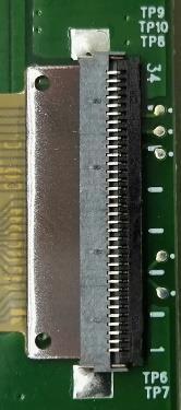
12 2.1.4 How to bridge EXT2 with the development kit If you will use our EXT2 board to bridge with your product or other development kit, there is Bridging header (J5) which is pin-to-pin to J4 and J6. The pin assignment is listed on the front side of PCB. Please use the 90 degree 20-pins header to solder on the backside of PCB like the picture below. We highly recommend cutting the protruding portion of the pin header in order to avoid breaking the EPD. After soldering the header on the EXT2 board, you are able to connect the bridging cable with the pin headers of other development kit or your product. Please note there is a white dot on the connector of bridging cable indicates the pin 1. EPD EXT2 with Cypress PSoC 4 BLE module 12 [User s Guide] Rev.01
13 The pin assignment is listed below. Table 2-2 Pin assignment of EXT2 header Jumper Pin No. Name Description 1 VCC Target supply voltage 2 GUARD2 TFT Breakage detection (option) 3 VPP Power Supply for OTP Programming 4 UART-TX TI LaunchPad default pin J4, J5 J5, J6 5 TS_SDA_MCU I 2 C data for external temperature sensor (GPIO) 6 TS_SCL_MCU I 2 C clock for external temperature sensor (GPIO) 7 SPI_CLK Clock for SPI 8 BUSY COG busy pin (GPIO) 9 D/C Data/Command control for itc (GPIO) 10 /RESET Reset signal. Low enable (GPIO) 11 PANEL_ON COG driver power control pin (GPIO) 12 DISCHARGE EPD discharge when EPD power off (GPIO) 13 BORDER_CONTROL (GUARD1) Border control pin for etc (GPIO) Breakage detection (option) 14 SPI_MISO Serial output from EPD to host MCU 15 SPI_MOSI Serial input from host MCU to EPD 16 RST/SBWTDIO TI LaunchPad default pin 17 TEST/SBWTCK TI LaunchPad default pin 18 /FLASH_CS On board flash chip select (GPIO) 19 /EPD_CS Chip Select. Low enable (GPIO) 20 GND Ground Bridge EXT2 board and Cypress PSoC 4 BLE kit After adjusting the jumpers of Cypress PSoC 4 BLE kit and soldering the 90 degree 20-pins header on J5 of EXT2 board, please use the bridging cable to connect the EXT2 board to Cypress PSoC 4 BLE kit. This 20 pins headers(j5) at the EXT2 board allows user to connect any development board. Please make sure the assembly signal headers of EXT2 board to align with Cypress PSoC 4 BLE kit ports. EPD EXT2 with Cypress PSoC 4 BLE module 13 [User s Guide] Rev.01
 13 P1.2 BUSY(EPD_Busy) 8 P0.5 /EPD_CS 19 P0.2 PWM/ D/C(EPD_DC) 9 P0.")
14 Figure 2-1 Connections between EXT2 and Cypress PSoC 4 BLE kit EPD Extension Board Gen2(EXT2) USB port PSoc 4 BLE kit Table 2-2 Connection of the EXT2 J5 header and PSoC 4 BLE kit port EXT2 J5 PSoC 4 BLE port TS_SCL_MCU 6 P3.5 SCL TS_SDA_MCU 5 P3.4 SDA TEST/SBWTCK/BS1 17 P1.5 Border_Control(EPD_border) 13 P1.2 BUSY(EPD_Busy) 8 P0.5 /EPD_CS 19 P0.2 PWM/ D/C(EPD_DC) 9 P0.4 Discharge(EPD_discharge) 12 P1.7 /REST(EPD_RST) 10 P1.0 /Flash_CS 18 P1.6 Panel_On 11 P1.1 SPI_CLK 7 P0.3 SPI_MISO 14 P0.1 SPI_MOSI 15 P0.0 VCC 1 V3.3 GND 20 GND EPD EXT2 with Cypress PSoC 4 BLE module 14 [User s Guide] Rev.01


15 2.1.6 Connect the EPD to the EXT2 board Connecting with 40-pins etc connector (J1) Open the connector Slide the FPC into connector Close the connector Note the pin1 is at the top side. Connecting with 24/26-pins itc connector (J3/J2) Open the connector Slide the FPC into connector Close the connector Note the pin1 is at the bottom side. EPD EXT2 with Cypress PSoC 4 BLE module 15 [User s Guide] Rev.01
 You will be asked to fill out your basic contact information and then you will receive an email to show the download link.")
16 2.2 Programming firmware to Cypress PSoC 4 BLE kit Before you proceed to get started with EXT2 kit, you have to download the EXT2 project source code from PDI website in advance. Download link: (Cypress PSoC 4 BLE kit) You will be asked to fill out your basic contact information and then you will receive an to show the download link. Please download and extract it (.RAR file format usually) Install Software PSoC Creator Follow these steps to install the BLE Pioneer Kit software: 1. Download the kit software from The software is available in the following formats: a. CY8CKIT-042-BLE Kit Complete Setup: This installation package contains the files related to the BLE Pioneer Kit. However, it does not include the Windows Installer or Microsoft.NET framework packages. If these packages are not on your computer, the installer directs you to download and install them from the Internet. b. CY8CKIT-042-BLE Kit Only Package: This executable file installs only the BLE Pioneer Kit contents, which include code examples, hardware files, and user documents. This package can be used if all the software prerequisites (listed in step 5) are installed on your computer. c. CY8CKIT-042-BLE DVD ISO: This file is a complete package, stored in a DVD-ROM image format, that you can use to create a DVD or extract using an ISO extraction program such as WinZip or WinRAR. The file can also be mounted similar to a virtual CD/DVD using virtual drive programs such as Virtual CloneDrive and MagicISO. This file includes all the required software, utilities, drivers, hardware files, and user documents. 2. Click Install CY8CKIT-042-BLE Kit to start the installation, as shown in Figure 2-2. Figure 2-2 Installer Screen EPD EXT2 with Cypress PSoC 4 BLE module 16 [User s Guide] Rev.01

17 3. Select the folder in which you want to install the CY8CKIT-042-BLE kit-related files. Choose the directory and click Next. 4. When you click Next, the CY8CKIT-042-BLE Kit installer automatically installs the required software, if it is not present on your computer. The following software packages are required: Note: For the Kit Only Package, download and install the following prerequisites. a. PSoC Creator 4.1 or Download the latest version from b. PSoC Programmer 3.26 or later: This is installed as part of PSoC Creator installation ( c. CySmart 1.2 SP1 or later: Download the latest version from Choose the Typical/Custom/Complete installation type in the Product Installation Overview window, as shown in Figure 2-2. Click Next after you select the installation type. Figure 2-3 Installation Overview 5. Read the license agreement and select I accept the terms in the license agreement to continue with installation. Click Next. 6. When the installation begins, a list of packages appears on the installation page. A green check mark appears next to each package after successful installation. 7. Click Finish to complete the CY8CKIT-042-BLE kit installation. 8. Enter your contact information or select the Continue Without Contact Information check box. Click Finish to complete the CY8CKIT-042-BLE kit installation. EPD EXT2 with Cypress PSoC 4 BLE module 17 [User s Guide] Rev.01

18 3. Working with Cypress PSoC Creator Project Code The Single driver will toggle between two images right away after programming the project. It helps you to simply test the basic global update function with your connected EPD. It s also the driving waveform that you will migrate to your product using the chosen EPD. The descriptions in this section will focus on the single driver. 3.1 EPD_drivers Project All of the driving waveform source code of supported EPDs with different FPL and driver are placed in this project FPL_drivers folder: You can find all the driving code under this folder for your chosen EPD. If you cannot find the model in this folder, please contact us to request the driving source code. The more advanced version of the project, the more driving code of EPDs will be supported under this folder. You will find the file format is like the configuration that we describe before: DriverType_(DriverID if etc)_size_fpl The captured picture below is for example. Your project code may be listed less or more than the example. EPD EXT2 with Cypress PSoC 4 BLE module 18 [User s Guide] Rev.01

19 - EPD_drivers.h: This file defines the main structures of EPD and COG type, the enumerations and the constants. - DriverType_Size_FPL.*: The most of driving source code for each supported EPD including the power on, initialization, update and power off stages. This is the waveform code you will migrate into your project for driving your chosen EPD. - itc_engine.*: This file is used for itc EPDs. In each of itc_size_fpl.c file, the code will always call functions from this itc_engine.c to extract the arrays (LUT) to get the corresponding data and set to each of predefined constant for later use. EPD EXT2 with Cypress PSoC 4 BLE module 19 [User s Guide] Rev.01


20 3.2 Change the different size EPD and image In main.c, you have to set both of dr_etc_bwb and sz_etc_epdsize to use the proper driving waveform. For example, if you attached 2.71 etc EPD, the code is as follows, #define USE_EPD_Type #define USE_EPD_Size dr_etc_bwb sz_etc_271 If you attached 2.15 itc epd, the code should be modified as follows, #define USE_EPD_Type #define USE_EPD_Size dr_itc_bwb sz_itc_215 images folder: You can convert any image file to a binary data and put it in this folder. EPD EXT2 with Cypress PSoC 4 BLE module 20 [User s Guide] Rev.01
21 4. Document revision history Rev. Date Comment Nov, First release - Supported driving etc: 1.44, 1.9, 2.0, 2.6 and itc: 2.15 EPD EXT2 with Cypress PSoC 4 BLE module 21 [User s Guide] Rev.01
22 5. Evaluation board/kit important notice This evaluation board/kit is intended for use for FURTHER ENGINEERING, DEVELOPMENT, DEMONSTRATION, OR EVALUATION PURPOSES ONLY. It is not a finished product and may not (yet) comply with some or any technical or legal requirements that are applicable to finished products, including, without limitation, directives regarding electromagnetic compatibility, recycling (WEEE), FCC, CE or UL (except as may be otherwise noted on the board/kit). Pervasive Displays (PDi) supplied this board/kit "AS IS," without any warranties, with all faults, at the buyer's and further users' sole risk. The user assumes all responsibility and liability for proper and safe handling of the goods. Further, the user indemnifies PDi from all claims arising from the handling or use of the goods. Due to the open construction of the product, it is the user's responsibility to take any and all appropriate precautions with regard to electrostatic discharge and any other technical or legal concerns. EXCEPT TO THE EXTENT OF THE INDEMNITY SET FORTH ABOVE, NEITHER USER NOR PDI SHALL BE LIABLE TO EACH OTHER FOR ANY INDIRECT, SPECIAL, INCIDENTAL, OR CONSEQUENTIAL DAMAGES. No license is granted under any patent right or other intellectual property right of PDi covering or relating to any machine, process, or combination in which such PDi products or services might be or are used. EPD EXT2 with Cypress PSoC 4 BLE module 22 [User s Guide] Rev.01
23 Pervasive Displays Inc. 4F, No. 28, Chuangye Rd.,Tainan Science Park, Tainan City (74144) Taiwan (R.O.C.) T: (+886)(6) Disclaimer: The information in this document is provided in connection with Pervasive Displays (PDi) products. No license, express or implied, by estoppel or otherwise, to any intellectual property right is granted by this document or in connection with the sale of PDi products. EXCEPT AS SET FORTH IN THE PDi TERMS AND CONDITIONS OF SALES LOCATED ON THE PDI WEBSITE, PDI ASSUMES NO LIABILITY WHATSOEVER AND DISCLAIMS ANY EXPRESS, IMPLIED OR STATUTORY WARRANTY RELATING TO ITS PRODUCTS INCLUDING, BUT NOT LIMITED TO, THE IMPLIED WARRANTY OF MERCHANTABILITY, FITNESS FOR A PARTICULAR PURPOSE, OR NON-INFRINGEMENT. IN NO EVENT SHALL PDI BE LIABLE FOR ANY DIRECT, INDIRECT, CONSEQUENTIAL, PUNITIVE, SPECIAL OR INCIDENTAL DAMAGES (INCLUDING, WITHOUT LIMITATION, DAMAGES FOR LOSS AND PROFITS, BUSINESS INTERRUPTION, OR LOSS OF INFORMATION) ARISING OUT OF THE USE OR INABILITY TO USE THIS DOCUMENT, EVEN IF PDI HAS BEEN ADVISED OF THE POSSIBILITY OF SUCH DAMAGES. PDi makes no representations or warranties with respect to the accuracy or completeness of the contents of this document and reserves the right to make changes to specifications and products descriptions at any time without notice. PDi does not make any commitment to update the information contained herein. Unless specifically provided otherwise, PDi products are not suitable for, and shall not be used in, automotive applications. PDi products are not intended, authorized, or warranted for use as components in applications intended to support or sustain life. EPD EXT2 with Cypress PSoC 4 BLE module 23 [User s Guide] Rev.01
User s Guide. EPD Extension Kit Gen2. Doc Rev. 05 (July 2017) Preface
 Preface") User s Guide Doc Rev. 05 (July 2017) EPD Extension Kit Gen2 Preface EPD* Extension Kit Generation 2 (EXT2) is a new generation of extension board to the Texas Instruments LaunchPad development platform
User s Guide Doc Rev. 05 (July 2017) EPD Extension Kit Gen2 Preface EPD* Extension Kit Generation 2 (EXT2) is a new generation of extension board to the Texas Instruments LaunchPad development platform
USER GUIDE. Atmel OLED1 Xplained Pro. Preface
 USER GUIDE Atmel OLED1 Xplained Pro Preface Atmel OLED1 Xplained Pro is an extension board to the Atmel Xplained Pro evaluation platform. The board enables the user to experiment with user interface applications
USER GUIDE. Atmel Segment LCD1 Xplained Pro. Preface
 USER GUIDE Atmel Segment LCD1 Xplained Pro Preface Atmel Segment LCD1 Xplained Pro is an extension board to the Atmel Xplained Pro evaluation platform. Segment LCD1 Xplained Pro is designed to kick-start
Ethernet1 Xplained Pro
 Ethernet1 Xplained Pro Part Number: ATETHERNET1-XPRO The Atmel Ethernet1 Xplained Pro is an extension board to the Atmel Xplained Pro evaluation platform. The board enables the user to experiment with
QT3 Xplained Pro. Preface. Atmel QTouch USER GUIDE
 Atmel QTouch QT3 Xplained Pro USER GUIDE Preface The Atmel QT3 Xplained Pro is an extension board, which enables the evaluation of a capacitive touch 12 key numpad in mutual capacitance configuration.
USER GUIDE. Atmel QT1 Xplained Pro. Preface
 USER GUIDE Atmel QT1 Xplained Pro Preface Atmel QT1 Xplained Pro kit is an extension board that enables evaluation of self- and mutual capacitance mode using the Peripheral Touch Controller (PTC) module.
USER GUIDE. Atmel QT6 Xplained Pro. Preface
 USER GUIDE Atmel QT6 Xplained Pro Preface Atmel QT6 Xplained Pro kit is a Xplained Pro extension board that enables the evaluation of a mutual capacitance touch suface using the Peripheral Touch Controller
USER GUIDE. ATWINC1500 Xplained Pro. Preface
 USER GUIDE ATWINC1500 Xplained Pro Preface Atmel ATWINC1500 Xplained Pro is an extension board to the Atmel Xplained Pro evaluation platform. The extension board allows to evaluate the Atmel ATWINC1510/1500
QT2 Xplained Pro. Preface. Atmel QTouch USER GUIDE
 Atmel QTouch QT2 Xplained Pro USER GUIDE Preface Atmel QT2 Xplained Pro kit is an extension board that enables the evaluation of a mutual capacitance touch surface using the Peripheral Touch Controller
AVR32901: EVKLCD100/EVKLCD101 Hardware User's Guide. 32-bit Microcontrollers. Application Note. Features. 1 Introduction
 AVR32901: EVKLCD100/EVKLCD101 Hardware User's Guide Features QVGA (EVKLCD100) or VGA (EVKLCD101) 5.7 LCD panel AC97 codec with touch controller Mono microphone input Resistive touch panel Stereo audio
USER GUIDE. Atmel PROTO1 Xplained Pro. Preface
 USER GUIDE Atmel PROTO1 Xplained Pro Preface The Atmel PROTO1 Xplained Pro extension kit is a development board that can be used to prototype small circuits and easy connect it to Xplained Pro MCU boards
Atmel CryptoAuthentication Starter Kit
 Atmel CryptoAuthentication Starter Kit Hardware User Guide Features 8-lead SOIC socket Supports the Atmel ATSHA204 CryptoAuthentication IC Supports communication protocols - I 2 C - SWI (Single wire interface)
APPLICATION NOTE. Atmel QT4 Xplained Pro User Guide ATAN0114. Preface
 APPLICATION NOTE Atmel QT4 Xplained Pro User Guide ATAN0114 Preface Atmel QT4 Xplained Pro kit is an extension board that enables evaluation of self-capacitance mode proximity and touch using the peripheral
I/O1 Xplained Pro. Preface. Atmel MCUs USER GUIDE
 Atmel MCUs I/O1 Xplained Pro USER GUIDE Preface Atmel I/O1 Xplained Pro is an extension board to the Atmel Xplained Pro evaluation platform. I/O1 Xplained Pro is designed to give a wide variety of functionality
Integrate TWR-EPD Software with MQX RTOS Based on the TWR-K21F120M Platform
 Freescale Semiconductor, Inc. Application Note Document Number: AN5069 Rev. 0, 01/2015 Integrate TWR-EPD Software with MQX RTOS Based on the TWR-K21F120M Platform 1 Introduction This application note describes
USER GUIDE. Atmel maxtouch Xplained Pro. Preface
 USER GUIDE Atmel maxtouch Xplained Pro Preface Atmel maxtouch Xplained Pro is an extension board to the Atmel Xplained Pro evaluation platform. The board enables the user to experiment with user interface
ATtiny104 Xplained Nano. Preface. AVR 8-bit Microcontrollers USER GUIDE
 AVR 8-bit Microcontrollers ATtiny104 Xplained Nano USER GUIDE Preface The Atmel ATtiny104 Xplained Nano evaluation kit is a hardware platform to evaluate the ATtiny104 microcontroller. Supported by the
Atmel AVR1926: XMEGA-B1 Xplained Getting Started Guide. 8-bit Atmel Microcontrollers. Application Note. Features. 1 Introduction
 Atmel AVR1926: XMEGA-B1 Xplained Getting Started Guide Features Easy to reprogram with just a USB cable and a preprogrammed boot loader Easy to debug code with PDI-based debugger/emulator Can be used with
AT88CK101 HARDWARE USER GUIDE. Atmel CryptoAuthentication Development Kit. Atmel CryptoAuthentication AT88CK101 Daughterboard
 AT88CK101 Atmel CryptoAuthentication Development Kit HARDWARE USER GUIDE Atmel CryptoAuthentication AT88CK101 Daughterboard Introduction The Atmel CryptoAuthentication AT88CK101 is a daughterboard that
AVR4018: Inertial Two (ATAVRSBIN2) Hardware User's Guide. 8-bit Microcontrollers. Application Note. Features. 1 Introduction
 Hardware User's Guide. 8-bit Microcontrollers. Application Note. Features. 1 Introduction") AVR4018: Inertial Two (ATAVRSBIN2) Hardware User's Guide Features Compatible with all Atmel AVR Xplain MCU boards Full nine-degree-of-freedom inertial sensing InvenSense three-axis MEMS gyroscope (IMU-3000
AVR4018: Inertial Two (ATAVRSBIN2) Hardware User's Guide Features Compatible with all Atmel AVR Xplain MCU boards Full nine-degree-of-freedom inertial sensing InvenSense three-axis MEMS gyroscope (IMU-3000
AT02667: XMEGA-E5 Xplained Hardware User's Guide. Features. Description. AVR XMEGA Microcontrollers APPLICATION NOTE
 AVR XMEGA Microcontrollers AT02667: XMEGA-E5 Xplained Hardware User's Guide APPLICATION NOTE Features Atmel AVR ATxmega32E5 microcontroller OLED display with 128 32 pixels resolution Ambient light sensor
Atmel AVR ATxmega384C3 microcontroller OLED display with 128x32 pixels resolution Analog sensors. Ambient light sensor Temperature sensor
 APPLICATION NOTE Atmel AVR1939: XMEGA-C3 Xplained Getting Started Guide Features Atmel AVR ATxmega384C3 microcontroller OLED display with 128x32 pixels resolution Analog sensors Ambient light sensor Temperature
Atmel AVR473: ATAVRSB202 Hardware User Guide. 8-bit Atmel Microcontrollers. Application Note. Features. 1 Introduction
 Atmel AVR473: ATAVRSB202 Hardware User Guide Features Atmel ATmega32HVB Smart Battery device evaluation and development kit High-side N-FETs 5mΩ sense resistor current measurements with 18-bit CC-ADC Input
Preliminary MK-CY-043. Data Sheet. Amulet Capacitive 4.3 GEMmodule. Introduction:
 Introduction: Amulet Capacitive 4.3 GEMmodule Data Sheet Preliminary The is a 4.3 fully integrated, production ready color module with smartphone-like features. Using Cypress TrueTouch technology, this
ATZB-SAMR21-XPRO. Preface. SmartConnect USER GUIDE
 SmartConnect ATZB-SAMR21-XPRO USER GUIDE Preface This user guide facilitates how to get started with the Atmel ATZB-SAMR21- XPRO extension board. ATZB-SAMR21-XPRO is targeted for evaluating the features
CMSIS DAP Setup. Document Version History Document Version ngxtechnologies.com 2
 Document Version History Document Version - 1.0 Author Vinayak ngxtechnologies.com 2 Table of Contents INTRODUCTION...4 REQUIREMENTS...4 HARDWARE...4 SOFTWARE...4 SETUP...4 DISCLAIMERS...8 ngxtechnologies.com
EPD Extension Kit User Manual
 EPD Extension Kit User Manual Date 2013/06/17 Revision 02 Model Name SK014AS0T1, SG020AS0T1, SM027AS0T1 龍亭新技股份有限公司 Pervasive Displays, Inc. No.71, Delun Rd., Rende Dist., Tainan City 71743, Taiwan (R.O.C.)
ATWINC3400-XPRO. Preface. SmartConnect USER GUIDE
 SmartConnect ATWINC3400-XPRO USER GUIDE Preface Atmel ATWINC3400-XPRO is an extension board to evaluate the performance of ATWINC3400-MR210CA, an IEEE 802.11 b/g/n RF/ Baseband/MAC Link Controller with
EDBG. Description. Programmers and Debuggers USER GUIDE
 Programmers and Debuggers EDBG USER GUIDE Description The Atmel Embedded Debugger (EDBG) is an onboard debugger for integration into development kits with Atmel MCUs. In addition to programming and debugging
USER GUIDE EDBG. Description
 USER GUIDE EDBG Description The Atmel Embedded Debugger (EDBG) is an onboard debugger for integration into development kits with Atmel MCUs. In addition to programming and debugging support through Atmel
DATASHEET. MK-070C-HP High Performance 7 Inch Capacitive Touch Display. Amulet. Technologies. July 2015 Revision A
 High Performance 7 Inch Capacitive Touch Display DATASHEET July 2015 Revision A Introduction The MK-070C is the newest family member in the Display Module product line. The new 7 Capacitive Display Module
ATBTLC1000 Xplained Pro. Preface. SmartConnect Bluetooth USER GUIDE
 SmartConnect Bluetooth ATBTLC1000 Xplained Pro USER GUIDE Preface Atmel ATBTLC1000 Xplained Pro is an extension board in the Atmel Xplained Pro evaluation platform. It is designed to demonstrate ultra-low
Atmel ATMXT143E touchscreen controller Capacitive touch ITO 320 x 240 pixel LCD display with SPI interface LED backlight
 APPLICATION NOTE Features Atmel AVR32936: mxt143e Xplained Hardware Users Guide Atmel maxtouch Touchscreen Controller 2.8 inch mxt143e LCD display module from Precision Design Associates (PDA) Atmel ATMXT143E
LPC2148 DEV BOARD. User Manual.
 LPC2148 DEV BOARD User Manual www.coineltech.com www.coineltech.com Designed by CoiNel Technology Solutions LLP No-816, 2 nd Floor, 4 th B Cross, 9 th A Main, RPC Layout, Vijaynagar, Bangalore-560040 State:
AT03975: Getting Started with SAM L21. Descripton. Features. SMART ARM-Based Microcontroller APPLICATION NOTE
 SMART ARM-Based Microcontroller AT03975: Getting Started with SAM L21 APPLICATION NOTE Descripton This application note aims at getting started with the Atmel SAM L21 ARM Cortex -M0+ based microconroller.
February 28,
 February 28, 2014 1 http://www.mattairtech.com/ Table of Contents Overview...3 Introduction...3 Features...4 Hardware...5 Main Header Pins...5 ISP Header Pins...6 Solder Jumpers...6 Onboard 3.3V, 250mA
Atmel AT32UC3A3256 microcontroller 64MBit SDRAM Analog input (to ADC) Temperature sensor RC filter
 Temperature sensor RC filter") APPLICATION NOTE Features Atmel AVR32918: UC3-A3 Xplained Hardware User s Guide Atmel AT32UC3A3256 microcontroller 64MBit SDRAM Analog input (to ADC) Temperature sensor RC filter I/O One mechanical button
APPLICATION NOTE Features Atmel AVR32918: UC3-A3 Xplained Hardware User s Guide Atmel AT32UC3A3256 microcontroller 64MBit SDRAM Analog input (to ADC) Temperature sensor RC filter I/O One mechanical button
SMART ARM-based Microcontrollers ATSAMD21E16LMOTOR USER GUIDE
 SMART ARM-based Microcontrollers ATSAMD21E16LMOTOR USER GUIDE Table of Contents 1. ATSAMD21E16L Microcontroller Card for Atmel Motor Control Starter Kit... 3 2. ATSAMD21E16LMOTOR Features... 4 3. ATSAMD21E16LMOTOR
Introduction. Rev.1.2
 Introduction The Revelation board is an evaluation tool which is designed to help to start working with Riverdi TFT panels with FT8XX controllers. It can also be used as a platform to build your own application.
AT06467: Getting started with SAM D09/D10/D11. Features. Description. SMART ARM-based Microcontrollers APPLICATION NOTE
 SMART ARM-based Microcontrollers AT06467: Getting started with SAM D09/D10/D11 APPLICATION NOTE Features Getting started with Atmel SMART SAM D09/D10/D11 microcontrollers and tools Getting started with
VENUS_ Driving Board and 39.6 Prism Display
 VENUS_ Driving Board and 39.6 Prism Display Table of Contents 1 Hardware Requirements... 1 (1) PACKAGE CONTENTS... 1 (2) VENUS Specification... 2 (3) Prism product Specification... 3 2 Hardware Guide...
F²MC-8L FAMILY MB89201 SERIES FLASH PROGRAMMING 8-BIT MICROCONTROLLER APPLICATION NOTE. Fujitsu Microelectronics Europe Application Note
 Fujitsu Microelectronics Europe Application Note MCU-AN-300001-E-V10 F²MC-8L FAMILY 8-BIT MICROCONTROLLER MB89201 SERIES FLASH PROGRAMMING APPLICATION NOTE Revision History Revision History Date 2005-02-09
TLK10081 EVM Quick Start Guide Texas Instruments Communications Interface Products
 TLK10081 EVM Quick Start Guide Texas Instruments Communications Interface Products 1 Board Overview +5 V Adapter Input Connector for voltage monitor board Connector for SMA break-out or FPGA board. Allows
AVR42789: Writing to Flash on the New tinyavr Platform Using Assembly
 AVR 8-bit Microcontrollers AVR42789: Writing to Flash on the New tinyavr Platform Using Assembly APPLICATION NOTE Table of Contents 1. What has Changed...3 1.1. What This Means and How to Adapt...4 2.
APPLICATION NOTE. Atmel AT01080: XMEGA E Schematic Checklist. Atmel AVR XMEGA E. Features. Introduction
 APPLICATION NOTE Atmel AT01080: XMEGA E Schematic Checklist Atmel AVR XMEGA E Features Power supplies Reset circuit Clocks and crystal oscillators PDI TWI Introduction This application note describes a
XDS220 Quick Start Guide
 XDS220 Quick Start Guide XDS220 1.0 SYSTEM REQUIREMENTS Cables 4 Adapters Quick Start Guide To operate the Spectrum Digital XDS220 JTAG Emulator with your system it needs to meet the following requirements:
User Manual: LPC1830-Xplorer LPC1830-Xplorer
 LPC1830-Xplorer 1 www.ngxtechnologies.com About NGX Technologies NGX Technologies is a premier supplier of development tools for the ARM7, ARM Cortex M0, M3 and M4 series of microcontrollers. NGX provides
ATtiny817 QTouch Moisture Demo User Guide. Description. Features. AVR 8-bit Microcontrollers USER GUIDE
 AVR 8-bit Microcontrollers ATtiny817 QTouch Moisture Demo User Guide USER GUIDE Description The Atmel ATtiny817 QTouch Moisture Demo Kit demonstrates the high performance capacitive touch support of the
[Type here] M907. Bluetooth 4.2 Low Energy/Zigbee/RF4CE/Thread SiP Module with MCU and integrated antenna
![[Type here] M907. Bluetooth 4.2 Low Energy/Zigbee/RF4CE/Thread SiP Module with MCU and integrated antenna](/thumbs/87/96540692.jpg "[Type here] M907. Bluetooth 4.2 Low Energy/Zigbee/RF4CE/Thread SiP Module with MCU and integrated antenna") [Type here] M907 Bluetooth 4.2 Low Energy/Zigbee/RF4CE/Thread SiP Module with MCU and integrated antenna Preliminary DATASHEET 19 th April, 2018 Table of Contents 1 Product Brief... 1 2 Features and Applications...
[Type here] M907 Bluetooth 4.2 Low Energy/Zigbee/RF4CE/Thread SiP Module with MCU and integrated antenna Preliminary DATASHEET 19 th April, 2018 Table of Contents 1 Product Brief... 1 2 Features and Applications...
LPC1788 Mio Board. User Manual. Revision 1.0 1
 User Manual http://coineltech.com Revision 1.0 1 Designed by CoiNel Technology Solutions LLP No-32, 2 nd Floor, HAPBCO Tower, 9 th Main, RPC Layout, Hampinagar, Bangalore-560040 State: Karnataka Country:
EVB-USB2640 Evaluation Board Revision A
 Copyright 2008 SMSC or its subsidiaries. All rights reserved. Circuit diagrams and other information relating to SMSC products are included as a means of illustrating typical applications. Consequently,
DATASHEET. 4.3 Embedded SPI Display. 4DLCD-FT843 Powered by the FTDI FT800 Video Engine. Document Date: 25 th September 2013 Document Revision: 0.
 DATASHEET 4.3 Embedded SPI Display 4DLCD-FT843 Powered by the FTDI FT800 Video Engine Document Date: 25 th September 2013 Document Revision: 0.4 Uncontrolled Copy when printed or downloaded. Please refer
DEMO MANUAL DC1338A LTC2990 I 2 C Temperature Voltage and Current Monitor DESCRIPTION
 DEMO MANUAL DC8A LTC990 I C Temperature Voltage and Current Monitor DESCRIPTION Demonstration circuit 8A features the LTC 990, a high performance temperature, voltage and current monitor that uses I C
Smart RF Device Family - Getting Started Guide. Features. Description. References ATAN0115 APPLICATION NOTE
 ATAN0115 Smart RF Device Family - Getting Started Guide APPLICATION NOTE Features Introduction to the Smart RF device family, including ATA82xx receivers, the ATA8520 transmitter and ATA85xx transceivers
APPLICATION NOTE. Atmel AT03304: SAM D20 I 2 C Slave Bootloader SAM D20. Description. Features
 APPLICATION NOTE Atmel AT03304: SAM D20 I 2 C Slave Bootloader SAM D20 Description As many electronic designs evolve rapidly there is a growing need for being able to update products, which have already
AT60142H/HT. Rad-Hard 512Kx8 Very Low Power CMOS SRAM ERRATA-SHEET. Active Errata List. Errata History. Abbreviations. 1.
 AT60142H/HT Rad-Hard 512Kx8 Very Low Power CMOS SRAM ERRATA-SHEET Active Errata List 1. Reading Error Errata History Lot Number Errata List All AT60142H lots 1 All AT60142HT lots 1 Abbreviations ATE :
PlainDAC. PolyVection. embedded audio solutions RASPBERRY PI SETUP GUIDE. PlainDAC chip on module page 1
 PlainDAC RASPBERRY PI SETUP GUIDE Audiophile digital-to-analog converter module with I2S input Document revision 1.0 August 2016 PlainDAC chip on module www.polyvection.com page 1 Table of Contents 1 Revision
USER GUIDE. ZigBit USB Stick User Guide. Introduction
 USER GUIDE ZigBit USB Stick User Guide Introduction This user guide describes how to get started with the Atmel ZigBit USB sticks. The ZigBit USB sticks is targeted for evaluating the USB features of the
SAM4 Reset Controller (RSTC)
") APPLICATION NOTE AT06864: SAM4 Reset Controller (RSTC) ASF PROGRAMMERS MANUAL SAM4 Reset Controller (RSTC) This driver for SAM devices provides an interface for the configuration and management of the
APPLICATION NOTE AT06864: SAM4 Reset Controller (RSTC) ASF PROGRAMMERS MANUAL SAM4 Reset Controller (RSTC) This driver for SAM devices provides an interface for the configuration and management of the
Quick Start Installation Guide
 XDS220 ISO USB/Ethernet CJTAG/JTAG Emulator Quick Start Installation Guide Items required for installation XDS220 ISO Emulator 4 Adapters 2 Cables 1.0 SYSTEM REQUIREMENTS 2 GB of free hard disk space Microsoft
APPLICATION NOTE. AT11008: Migration from ATxmega16D4/32D4 Revision E to Revision I. Atmel AVR XMEGA. Introduction. Features
 APPLICATION NOTE AT11008: Migration from ATxmega16D4/32D4 Revision E to Revision I Atmel AVR XMEGA Introduction This application note lists out the differences and changes between Revision E and Revision
EVB-USB82640 Evaluation Board Revision A User Manual
 EVB-USB82640 Evaluation Board Revision A User Manual Copyright 2009 SMSC or its subsidiaries. All rights reserved. Circuit diagrams and other information relating to SMSC products are included as a means
USB-to-I2C Basic. Hardware User s Manual.
 USB-to-I2C Basic Hardware User s Manual http://www.i2ctools.com/ Information provided in this document is solely for use with the USB-to-I2C product from SB Solutions, Inc. SB Solutions, Inc. reserves
Raspberry Pi shield board
 Raspberry Pi shield board Table of Contents Hardware Guide 1 1 Hardware Requirements 1 (1) PACKAGE CONTENTS 1 (2) Feature 1 2 Hardware Guide 2 (1) HARDWARE REQUIREMENTS 2 (2) HARDWARE CONNECTION 3 (3)
DATASHEET 4D SYSTEMS TURNING TECHNOLOGY INTO ART. microusb Programming Adaptor. USB to UART Serial Bridge
 TURNING TECHNOLOGY INTO ART DATASHEET microusb Programming Adaptor µusb-pa5 USB to UART Serial Bridge Document Date: 27 th November 2013 Document Revision: 1.1 Uncontrolled Copy when printed or downloaded.
January 2003 Digital Audio Products SLEU031
 User s Guide January 2003 Digital Audio Products SLEU031 IMPORTANT NOTICE Texas Instruments Incorporated and its subsidiaries (TI) reserve the right to make corrections, modifications, enhancements, improvements,
TMS320C5502 ezdsp Quick Start Guide
 TMS320C5502 ezdsp Quick Start Guide C5502 ezdsp USB Cable DVD Quick Start Guide 1.0 SYSTEM REQUIREMENTS To operate the Spectrum Digital XDS100 JTAG Emulator with your system it needs to meet the following
UM PCAL6524 demonstration board OM Document information
 Rev. 1 23 September 2015 User manual Document information Info Content Keywords OM13320 Fm+ development kit, OM13260 Fm+ I2C bus development board, OM13303 GPIO target board Abstract Installation guide
DATASHEET 4D SYSTEMS. uusb-pa5 uusb-pa5-ii. microusb Programming Adaptor TURNING TECHNOLOGY INTO ART. USB to UART Serial Bridge
 DATASHEET TURNING TECHNOLOGY INTO ART microusb Programming Adaptor -II USB to UART Serial Bridge Document Date: 17 th July 2015 Document Revision: 2.0 Uncontrolled Copy when printed or downloaded. Please
UM LPC General Purpose Shield (OM13082) Rev November Document information. Keywords
 Rev November Document information. Keywords") Rev. 1.0 17 November 2015 User manual Document information Info Content Keywords LPCXpresso, LPC General Purpose Shield, OM13082 Abstract LPC General Purpose Shield User Manual Revision history Rev Date
Rev. 1.0 17 November 2015 User manual Document information Info Content Keywords LPCXpresso, LPC General Purpose Shield, OM13082 Abstract LPC General Purpose Shield User Manual Revision history Rev Date
EVB-USB2514Q36-BAS, USB2513 and USB Pin QFN Evaluation Board, Revision C User Manual
 EVB-USB2514Q36-BAS, USB2513 and USB2512 36-Pin QFN Evaluation Board, Revision C User Manual Copyright 2009 SMSC or its subsidiaries. All rights reserved. Circuit diagrams and other information relating
This user guide describes how to run the Atmel ATWINC3400 Bluetooth Low Energy (BLE) Provisioning demo from out-of-box conditions.
 Provisioning demo from out-of-box conditions.") ATWINC3400 BLE ATWINC3400 BLE Provisioning - Setup and Usage USER GUIDE Introduction This user guide describes how to run the Atmel ATWINC3400 Bluetooth Low Energy (BLE) Provisioning demo from out-of-box
ATWINC3400 BLE ATWINC3400 BLE Provisioning - Setup and Usage USER GUIDE Introduction This user guide describes how to run the Atmel ATWINC3400 Bluetooth Low Energy (BLE) Provisioning demo from out-of-box
AVR1922: Xplain Board Controller Firmware 8-bit Microcontrollers Application Note Features 1 Introduction
 AVR1922: Xplain Board Controller Firmware Features USB interface - Mass-storage to on-board DataFlash memory Atmel AVR XMEGA TM reset control 1 Introduction The Xplain board controller, an AT90USB1287,
STK521. User Guide B AVR 01/12
 STK521... User Guide Table of Contents Section 1 1 Introduction 1 Features 2 Section 2 3 Using the STK521 Top Module 3 Connecting the Atmel STK521 to the Atmel STK500 Starter Kit 3 Powering the STK521
Single Cell Battery Power Solution
 Single Cell Battery Power Solution Input 5V DC Output 2.80.. 4.28V (dependent on charge state of battery) Current limited to 500mA max. Devices TPS2113A Autoswitching Power MUX TPD4S012 4-Channel USB ESD
Apollo2 EVB Quick Start Guide
 Apollo2 EVB Quick Start Guide Doc ID: QS-A2-1p00 Revision 1.0 June 2017 QS-A2-1p00 Page 1 of 11 2017 Ambiq Micro, Inc. Table of Content 1. Introduction...3 2. Documentation Revision History...3 3. Overview
EVB-USB2250 User Manual Revision B
 Copyright 2009 SMSC or its subsidiaries. All rights reserved. Circuit diagrams and other information relating to SMSC products are included as a means of illustrating typical applications. Consequently,
February 2003 PMP EVMs SLVU081
 User s Guide February 2003 PMP EVMs SLVU081 IMPORTANT NOTICE Texas Instruments Incorporated and its subsidiaries (TI) reserve the right to make corrections, modifications, enhancements, improvements, and
USB-to-I2C. Professional Hardware User s Manual.
 USB-to-I2C Professional Hardware User s Manual https://www.i2ctools.com/ Information provided in this document is solely for use with the USB-to-I2C Professional product from SB Solutions, Inc. SB Solutions,
USER GUIDE. Atmel SAM G55 Xplained Pro. Preface
 USER GUIDE Atmel SAM G55 Xplained Pro Preface The Atmel SAM G55 Xplained Pro evaluation kit is a hardware platform to evaluate the ATSAMG55J19 microcontroller. This kit is supported by the Atmel Studio
Atmel AVR1619: XMEGA-B1 Xplained Demonstration. 8-bit Atmel Microcontrollers. Application Note. Features. 1 Introduction
 Atmel AVR1619: XMEGA-B1 Xplained Demonstration Features Atmel ATxmega128B1 Atmel XMEGA -B1 Xplained kit compatible On-board LCD display USB 2.0 Full speed composite device - Mass Storage interface with
APPLICATION NOTE. AT03324: Atmel REB212BSMA-EK Quick Start Guide. Atmel MCU Wireless. Introduction
 APPLICATION NOTE AT03324: Atmel REB212BSMA-EK Quick Start Guide Atmel MCU Wireless This application note briefly describes how to set up and run the pre-flashed applications supplied with the Atmel REB212BSMA
UM NXP USB PD shield board user manual COMPANY PUBLIC. Document information
 Rev. 0.3 19 June 2017 User manual COMPANY PUBLIC Document information Information Content Keywords Abstract OM13588, USB Type-C, PD (power delivery), Alt-mode-DP, Host, Dock This user manual presents demonstration
TPS62290EVM-279. User's Guide SLVU217 July 2007
 User's Guide SLVU217 July 2007 TPS62290EVM-279 This user s guide describes the characteristics, operation, and use of the TPS62290EVM-279 evaluation module (EVM). This EVM demonstrates the Texas Instruments
CE PSoC 4: Time-Stamped ADC Data Transfer Using DMA
 CE97091- PSoC 4: Time-Stamped ADC Data Transfer Using DMA Objective This code example uses a DMA channel with two descriptors to implement a time-stamped ADC data transfer. It uses the Watch Dog Timer
AT11512: SAM L Brown Out Detector (BOD) Driver. Introduction. SMART ARM-based Microcontrollers APPLICATION NOTE
 Driver. Introduction. SMART ARM-based Microcontrollers APPLICATION NOTE") SMART ARM-based Microcontrollers AT11512: SAM L Brown Out Detector (BOD) Driver APPLICATION NOTE Introduction This driver for Atmel SMART ARM -based microcontrollers provides an interface for the configuration
SMART ARM-based Microcontrollers AT11512: SAM L Brown Out Detector (BOD) Driver APPLICATION NOTE Introduction This driver for Atmel SMART ARM -based microcontrollers provides an interface for the configuration
ATmega324PB Xplained Pro. Preface. AVR 8-bit Microcontrollers USER GUIDE
 AVR 8-bit Microcontrollers ATmega324PB Xplained Pro USER GUIDE Preface The Atmel ATmega324PB Xplained Pro evaluation kit is a hardware platform to evaluate the ATmega324PB microcontroller. Supported by
SAMDA1 Xplained Pro. Preface. SAMDA1 Xplained Pro USER GUIDE
 SAMDA1 Xplained Pro SAMDA1 Xplained Pro USER GUIDE Preface The Atmel SAMDA1 Xplained Pro evaluation kit is a hardware platform to evaluate the SAMDA1J16A microcontroller. Supported by the Atmel Studio
DATASHEET 4D SYSTEMS. 4D Raspberry Pi Serial Adaptor TURNING TECHNOLOGY INTO ART. 4D-Serial-Pi-Adaptor
 DATASHEET TURNING TECHNOLOGY INTO ART 4D Raspberry Pi Serial Adaptor 4D-Serial-Pi-Adaptor Document Date: 21 st August 2014 Document Revision: 1.2 Uncontrolled Copy when printed or downloaded. Please refer
Native route discovery algorithm
 Native route discovery algorithm Starting conditions Node 1 needs to send data to node Routing tables are empty There is no direct path between node 1 and node Destination Next hop Destination Next hop
DATASHEET 4D SYSTEMS. 4D Raspberry Pi Serial Adaptor TURNING TECHNOLOGY INTO ART. 4D-Serial-Pi-Adaptor
 TURNING TECHNOLOGY INTO ART DATASHEET 4D-Serial-Pi-Adaptor Document Date: 20 th November 2012 Document Revision: 1.0 Uncontrolled Copy when printed or downloaded. Please refer to the 4D Systems website
SBAT90USB162 Atmel. SBAT90USB162 Development Board User s Manual
 SBAT90USB162 Atmel AT90USB162 Development Board User s manual 1 1. INTRODUCTION Thank you for choosing the SBAT90USB162 Atmel AT90USB162 development board. This board is designed to give a quick and cost-effective
ATAES132A Firmware Development Library. Introduction. Features. Atmel CryptoAuthentication USER GUIDE
 Atmel CryptoAuthentication ATAES132A Firmware Development Library USER GUIDE Introduction This user guide describes how to use the Atmel CryptoAuthentication ATAES132A Firmware Development Library with
October 2002 PMP Portable Power SLVU074
 User s Guide October 2002 PMP Portable Power SLVU074 IMPORTANT NOTICE Texas Instruments Incorporated and its subsidiaries (TI) reserve the right to make corrections, modifications, enhancements, improvements,
DATASHEET 4D SYSTEMS. 4D Arduino Adaptor Shield TURNING TECHNOLOGY INTO ART. 4Display-Adaptor-Shield
 TURNING TECHNOLOGY INTO ART DATASHEET 4Display-Adaptor-Shield Document Date: 20 th November 2012 Document Revision: 1.0 Uncontrolled Copy when printed or downloaded. Please refer to the 4D Systems website
DEMO MANUAL DC1506A LTC4361 Overvoltage/ Overcurrent Protection Controller DESCRIPTION
 DESCRIPTION Demonstration circuit DC1506A features the LTC 4361 an overvoltage/overcurrent protection controller that safeguards 2.5V to 5.5V systems from input supply overvoltage. The LTC4361 is designed
[Type here] M905. Bluetooth 4.2 Low Energy SiP Module with MCU and integrated antenna
![[Type here] M905. Bluetooth 4.2 Low Energy SiP Module with MCU and integrated antenna](/thumbs/95/123247090.jpg "[Type here] M905. Bluetooth 4.2 Low Energy SiP Module with MCU and integrated antenna") [Type here] M905 Bluetooth 4.2 Low Energy SiP Module with MCU and integrated antenna Preliminary DATASHEET 23 th January, 2017 Table of Contents 1 Product Brief... 1 2 Features and Applications... 2 3
[Type here] M905 Bluetooth 4.2 Low Energy SiP Module with MCU and integrated antenna Preliminary DATASHEET 23 th January, 2017 Table of Contents 1 Product Brief... 1 2 Features and Applications... 2 3
DATASHEET 4D SYSTEMS. 4D Raspberry Pi Serial Adaptor TURNING TECHNOLOGY INTO ART. 4D-Serial-Pi-Adaptor
 DATASHEET TURNING TECHNOLOGY INTO ART 4D Raspberry Pi Serial Adaptor 4D-Serial-Pi-Adaptor Document Date: 4 th September 2013 Document Revision: 1.1 Uncontrolled Copy when printed or downloaded. Please
OLED display with pixels resolution Ambient light sensor CPU load Analog filter Quadrature Encoder with push button Digital I/O
 APPLICATION NOTE Atmel AT02657: XMEGA-E5 Xplained Software User Guide Features OLED display with 128 32 pixels resolution Ambient light sensor CPU load Analog filter Quadrature Encoder with push button
CE CY8CKIT-042-BLE F-RAM Data Logger
 CE210988 - CY8CKIT-042-BLE F-RAM Data Logger Objective This example project is based on a PSoC Creator starter design for the PSoC 4 device. It demonstrates how F-RAM can be used with the PSoC to capture