Halloween Pumpkinusing. Wednesday, October 17, 12
|
|
|
- Chad Dean
- 5 years ago
- Views:
Transcription

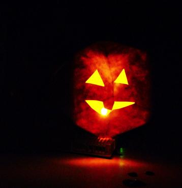
1 Halloween Pumpkinusing Blink LED 1
 3 Male")

2 What you will need: 1 MSP-EXP430G2 1 3 x 2 Breadboard Ohm Resistors 3 LED s (in Red Color Range) 3 Male to female jumper wires 1 Double AA BatteryPack 2 AA Batteries Computer running Energia +computer running Energia 2


3 Download Energia Visit go to the GETTING STARTED page follow the directions Download the LaunchPad Drivers Download the Energia application 3


4 Connect the LaunchPad We will be testing the microcontroller and running the Blink LED Program. 1. Start the Energia Application on your computer. 2. Open your LaunchPad and connect the USB Cable 3. Connect the LaunchPad to your computer. 4. Verify it all works. You should see a green and red LED light blink back and forth 4


5 Run LED Blink With the LaunchPad Connected. 1. Verify your board is selected and is correct. Tools--> Board-->MSP430G2553 (16 MHZ) 2. Open the Example File: Blink LED File--> Examples-->Basics--> Blink 5

6 Load Blink Load the LED Blink Example. Hit Upload Upload Program: click this to get the program onto the microcontroller. The Program getting loaded this is where you write and edit your code. Board Status: this is where you verify which board you are using and what COM Port. Status Window and Bar Status of Program Details of what was loaded Success = white 6
7 Load Blink Your LaunchPad should now be blinking the LED on for 1 second and off for 1 second. Don t close out this program, you ll be using it again. /* Blink Turns on an LED on for one second, then off for one second, repeatedly. This example code is in the public domain. */ void setup() { // initialize the digital pin as an output. // Pin 14 has an LED connected on most Arduino boards: pinmode(14, OUTPUT); } Program Start and Loop when turn on void loop() { digitalwrite(14, HIGH); // set the LED on delay(1000); // wait for a second digitalwrite(14, LOW); // set the LED off delay(1000); // wait for a second } Start the Program. Declare Pin 14 as an Output. Pin 14 is Pin P.16 on the LaunchPad If you decide to change which pin you want to use, you will need to declare it here. take Pin 14 and make it HIGH (this turns on the LED) Hold it for 1000 milli seconds (1 second) take Pin 14 and make it LOW (this turns off the LED) Hold it for 1000 milli seconds (1 second) 7

8 Part 1 Done! LED Blinking on LaunchPad! 8


 Red Wire (to pin")
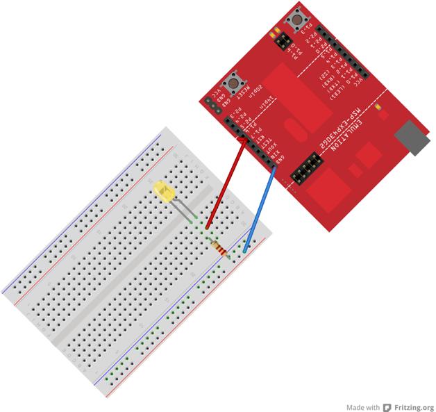
9 Wire Up Breadboard 1 3 x 2 Breadboard Ohm Resistor 1 LED any of the three 2 Male to female jumper wires Blue (GND or - wire) Red Wire (to pin or the +) 9

10 How does a Breadboard Work? Jumper cables are matched to the color. Rows are connected together sharing a common Bus or Wire connecting anything on the same row will be like wiring them together. To VCC or + To GND Columns are connected together sharing a common Bus or Wire The + and the - columns provide power, to get power to the rows, you need to connect the row to one of the columns. (usually the - ) 10

 2.")
.")


 and the shorter Lead on Row 8 (same")
11 You will be creating this circuit. 1. Connect this jumper cable to VCC on the LaunchPad and to a Row on the side of the breadboard we are working on (use Row 7 for this purpose) 2. Connect the resistor from the negative (blue) column to a row on the breadboard. (use row 8 for this purpose). 3. The LED has a long and a short. This is the positive and the negative sides. Connect the LED to 2 rows, positive side on the row above. In this case, place the longer lead on Row 7 (same row as the red jumper) and the shorter Lead on Row 8 (same row as the resistor). 4. Connect this jumper cable to GND on the LaunchPad and to the - Row on the same side we are working on. 11
 connection to GND (-) //the blue jumper wire and a positive connection (one of the red jumpers that go to a pin on the MSP430.")
12 Part 2 Done! Congratulations! The LED Should be Blinking! If you want to add more LED s you can add those on other parts of the board. Just make sure that the LED has a resistor (you have 2 extra) connection to GND (-) //the blue jumper wire and a positive connection (one of the red jumpers that go to a pin on the MSP430. You can test the LED by connecting a Red Jumper Wire to VCC at any time (always is on). 12
13 13
14 Additional: - Change out the LED that is used, use the red, try the large yellow one -Try to wire another LED using VCC (to keep it on constantly) 14
. You may want to change that, to make sure that your yellow LED light isn t colored by the green LED light.")
15 Change the Program- Change the PIN Notice the original LED on the board (Green one) is blinking with the yellow LED you ve put on the breadboard. This is because both outputs are tied to the same power source (PIN 14). You may want to change that, to make sure that your yellow LED light isn t colored by the green LED light. To do that, you will need to change the PIN that the Yellow LED is blinking off of. 1. Look at your BlinkLED program (it should still be open). 2. Look for anyplace you see Pin 14 declared. 3. Replace the Pin 14, with Pin Hit Upload. 15

16 Change the Program- Change the PIN The Green LED should stop flashing on and off steadily. The only LED on is the one by the USB Cable (indicating Power). It s time to adjust the wiring to reflect the change. The power has moved from Pin 14 to Pin 6. We will need to take the Jumper Cable from Pin 14 and move it to Pin 6. These numbers may be different than the ones on the writing or silkscreen of the LaunchPad. The Pins that the program is referring to are the ones on the actual device the MSP430G2553. In this case you will be moving the Jumper on the LaunchPad from P1.6 on the right hand side to P1.4 on the left hand side. The Yellow LED Should Start Blinking every 1 second again. Pin VCC P1.0 P1.1 P.1.2 P1.3 P1.4 P1.5 P.2.0 P2.1 P2.2 Pin Pin GND XIN XOUT TEST RST P.1.7 P.1.6 P2.5 P2.4 P2.3 Pin Pins on the device coordinated with the silkscreening on the LaunchPad IF you change the device, the pin assignments will change. 16

17 Blinking LED only on the Breadboard! Try changing the pin around for the LED on the breadboard. Remember you have to change the code and then move the jumper 17
18 Change the Program- Change the Flashing Now that you have the LED on the breadboard flashing on it s own for 1 second on and 1 second off, it s time to change the timing. Go back to your code window In the code there is a function delay(1000). This means, hold the function previous for 1000 milliseconds = 1 Second. You ll notice that the number is in black. This means that you can change it whatever you d like. Once you change the number, hit UPLOAD and watch the difference in how the LED on the breadboard behaves. I suggest trying 5000 for and 2000 then trying 35 and 70 *If you run into a situation where the LED Stops turning on or seems to be on all the time and not turning off, you may have the delay interval too long or too short. Change the numbers closer to 1000 to test it. For something similar to a candle flicker, use the shorter times like 35 on and 70 off 18


19 Preview of Next Lesson: Multiple LED s perhaps your LED isn t bright enough to light your pumpkin, or you want to get a better flicker effect. Adding multiple may be the route you d like to take. If you only want to have an LED flickr the same way as the first, you only need to add the LED next to the existing one. If you want to have both LED s flash at different rates, you will need to change the program and add that LED. Just remember, you will first need to wire up the breadboard with the additional LEDs and incorporate the new LED s into the program. This is a preview of the next lesson. All of the LED s connected to same Rows so they flicker at the same rate. Large LED is constantly on with the red and yellow flickering at the same rate. 19

20 Preview Cont. 20
21 Additional Info 21
 you can get an external battery pack USB Powered 2.) you can connect using AA batteries (included for some). IF you select Option 1, it is the easiest.")
22 Connecting your project to a Batteryyou might want to have your project more portable than needing to have a USB cable connected to your computer (e.g. inside of a pumpkin). You have a few options: 1. ) you can get an external battery pack USB Powered 2.) you can connect using AA batteries (included for some). IF you select Option 1, it is the easiest. Just replace the computer with the Battery Pack and turn on. The LaunchPad will continue to be powered through the on-board USB. However, Option 2 does require a little work, but may be more cost effective. 22


23 Connecting your project to a Battery AA pack 1. You will need to make sure to find the negative and positive wires on the battery pack. This should align nicely with if the battery wire starts at the negative terminal or positive. Negative or Black Wire 2. Follow these negative and positive to the ends to the white connector. Positive or Red Wire 23


24 3. Connect the White Connector to the GND and VCC in the bottom right hand corner of the LaunchPad. The silkscreen reads GND GND VCC which corresponds to the connector s - blank + DON T PLUG IN BACKWARDS. There is very little protection circuitry on the LaunchPad! The LaunchPad should light up now. once the LaunchPad is powered and you see your program running, you will need to disconnect the headers. These headers connect power from the battery to the power source of the USB cable. Since you do not need the USB to save battery life you should disconnect that portion. However, if you think you may want to re-program the Launchpad, you will need to keep the headers and put them on before trying to re-program it. (the headers just slide off the tops of the pins). 24

25 Power and JTAG Headers this connects the microcontroller to the USB Power and the data. Disconnect to save battery life. Match VCC to red and GND to Black. Don t plug in backwards. Header Pins, must replace these in order to re-program the microcontroller 25
26 Energia Let s first look at Energia Menu Bar Check Program: check your code without having to re-program the microcontroller. Upload Program: click this to get the program onto the microcontroller. Editor Window: this is where you write and edit your code. Board Status: this is where you verify which board you are using and what COM Port. Debug Window: if there are errors in your code they will appear here in orange. This is where we can see successful actionsdisplayed in white. 26

27 Sketch The program in Energia is called a Sketch Set-Up: You will need to set up any thing that the microcontroller uses. This is where you declare what Pins and how they are used. Pins are the different leads on the microcontroller. stage. this needs a declaration of a section void and then the section type setup followed by a empty parenthesis (){ contents} You can add as many of these are you want, but it will break the program into chapters Comments: Anything in Green is a Comment. You can start a comment by writing the ffor a single line write //comment or for many lines /*comment*/ Program:: This is what initiates a program. This is where you tell the microcontroller what to do. native functions or Actions. these are instructions that are part of Energia. They show up as orange. if you use one, you will need function (what you are targeting, TYPE) You may choose which Action you want;, but you cannot change how the Action works. program declarations required program stage- choose comments- whatever you wish, does not load into microcontroller functions- confined to a select list user inputs - whatever you wish, as long as it makes sense within the action it s being used in TYPE: you can choose from the list ; (semi colon) designates the end of a function, you need one for every function { (open bracket) begin a section } (close bracket) we end a section 27
Note. The above image and many others are courtesy of - this is a wonderful resource for designing circuits.
 Robotics and Electronics Unit 2. Arduino Objectives. Students will understand the basic characteristics of an Arduino Uno microcontroller. understand the basic structure of an Arduino program. know how
Counter & LED (LED Blink)
") 1 T.R.E. Meeting #1 Counter & LED (LED Blink) September 17, 2017 Contact Info for Today s Lesson: President Ryan Muller mullerr@vt.edu 610-573-1890 Learning Objectives: Learn how to use the basics of Arduino
1 T.R.E. Meeting #1 Counter & LED (LED Blink) September 17, 2017 Contact Info for Today s Lesson: President Ryan Muller mullerr@vt.edu 610-573-1890 Learning Objectives: Learn how to use the basics of Arduino
StenBOT Robot Kit. Stensat Group LLC, Copyright 2018
 StenBOT Robot Kit 1 Stensat Group LLC, Copyright 2018 Legal Stuff Stensat Group LLC assumes no responsibility and/or liability for the use of the kit and documentation. There is a 90 day warranty for the
University of Hull Department of Computer Science C4DI Interfacing with Arduinos
 Introduction Welcome to our Arduino hardware sessions. University of Hull Department of Computer Science C4DI Interfacing with Arduinos Vsn. 1.0 Rob Miles 2014 Please follow the instructions carefully.
Robotics and Electronics Unit 5
 Robotics and Electronics Unit 5 Objectives. Students will work with mechanical push buttons understand the shortcomings of the delay function and how to use the millis function. In this unit we will use
Digital Pins and Constants
 Lesson Lesson : Digital Pins and Constants Digital Pins and Constants The Big Idea: This lesson is the first step toward learning to connect the Arduino to its surrounding world. You will connect lights
Prototyping & Engineering Electronics Kits Basic Kit Guide
 Prototyping & Engineering Electronics Kits Basic Kit Guide odysseyboard.com Please refer to www.odysseyboard.com for a PDF updated version of this guide. Guide version 1.0, February, 2018. Copyright Odyssey
Lab 01 Arduino 程式設計實驗. Essential Arduino Programming and Digital Signal Process
 Lab 01 Arduino 程式設計實驗 Essential Arduino Programming and Digital Signal Process Arduino Arduino is an open-source electronics prototyping platform based on flexible, easy-to-use hardware and software. It's
Arduino Micro Breadboard Laboratory Interface Processor (Micro BLIP) User Manual
 User Manual") Arduino Micro Breadboard Laboratory Interface Processor (Micro BLIP) MicroBLIP circuit board v2.0 Operating System v2.0.0 1/22/2019 User Manual 2 1 Setup and Operation 1.1 Introduction For the past ten
Arduino Micro Breadboard Laboratory Interface Processor (Micro BLIP) MicroBLIP circuit board v2.0 Operating System v2.0.0 1/22/2019 User Manual 2 1 Setup and Operation 1.1 Introduction For the past ten
Arduino 101 AN INTRODUCTION TO ARDUINO BY WOMEN IN ENGINEERING FT T I NA A ND AW E S O ME ME NTO R S
 Arduino 101 AN INTRODUCTION TO ARDUINO BY WOMEN IN ENGINEERING FT T I NA A ND AW E S O ME ME NTO R S Overview Motivation Circuit Design and Arduino Architecture Projects Blink the LED Switch Night Lamp
micro:bit Lesson 2. Controlling LEDs on Breadboard
 micro:bit Lesson 2. Controlling LEDs on Breadboard Created by Simon Monk Last updated on 2018-03-09 02:39:14 PM UTC Guide Contents Guide Contents Overview Parts BBC micro:bit Half-size breadboard Small
1/Build a Mintronics: MintDuino
 1/Build a Mintronics: The is perfect for anyone interested in learning (or teaching) the fundamentals of how micro controllers work. It will have you building your own micro controller from scratch on
Procedure: Determine the polarity of the LED. Use the following image to help:
 Section 2: Lab Activity Section 2.1 Getting started: LED Blink Purpose: To understand how to upload a program to the Arduino and to understand the function of each line of code in a simple program. This
ROBOTLINKING THE POWER SUPPLY LEARNING KIT TUTORIAL
 ROBOTLINKING THE POWER SUPPLY LEARNING KIT TUTORIAL 1 Preface About RobotLinking RobotLinking is a technology company focused on 3D Printer, Raspberry Pi and Arduino open source community development.
Objectives: Learn how to input and output analogue values Be able to see what the Arduino is thinking by sending numbers to the screen
 Objectives: Learn how to input and output analogue values Be able to see what the Arduino is thinking by sending numbers to the screen By the end of this session: You will know how to write a program to
Quick Start by JP Liew
 Quick Start Page 1 of 8 Quick Start by JP Liew Thank you backing our Kickstarter project. Before we get underway with setting up your MicroView, you should make sure you have got everything you need. Unboxing
9 Output Devices: Buzzers
 9 Output Devices: Buzzers Project In this project, you will learn how to connect and control LEDs (Light Emitting Diode) and a buzzer with the Raspberry Pi. Components In addition to your Raspberry Pi,
Arduino 05: Digital I/O. Jeffrey A. Meunier University of Connecticut
 Arduino 05: Digital I/O Jeffrey A. Meunier jeffm@engr.uconn.edu University of Connecticut About: How to use this document I designed this tutorial to be tall and narrow so that you can read it on one side
USB Type A Female Breakout Hookup Guide
 Page 1 of 7 USB Type A Female Breakout Hookup Guide Introduction If you have a microcontroller that can act as a USB host, then you will need a way to plug in USB cables and devices. The USB Type A Female
TA0013 ARDUINO RFID UNO STARTER KIT
 TA0013 ARDUINO RFID UNO STARTER KIT Overview TA0013 This Arduino Uno ultimate project kit includes comprehensive range of components to get you started in building and experimenting with Arduino projects.
Blinking an LED 1 PARTS: Circuit 2 LED. Wire. 330Ω Resistor
 Circuit PIN 3 RedBoard Blinking an LED LED (Light-Emitting Diode) Resistor (33 ohm) (Orange-Orange-Brown) LEDs (light-emitting diodes) are small, powerful lights that are used in many different applications.
SX1509 I/O Expander Breakout Hookup Guide
 Page 1 of 16 SX1509 I/O Expander Breakout Hookup Guide Introduction Is your Arduino running low on GPIO? Looking to control the brightness of 16 LEDs individually? Maybe blink or breathe a few autonomously?
8051 Intermidiate Development Board. Product Manual. Contents. 1) Overview 2) Features 3) Using the board 4) Troubleshooting and getting help
 Overview 2) Features 3) Using the board 4) Troubleshooting and getting help") 8051 Intermidiate Development Board Product Manual Contents 1) Overview 2) Features 3) Using the board 4) Troubleshooting and getting help 1. Overview 2. Features The board is built on a high quality FR-4(1.6
8051 Intermidiate Development Board Product Manual Contents 1) Overview 2) Features 3) Using the board 4) Troubleshooting and getting help 1. Overview 2. Features The board is built on a high quality FR-4(1.6
OpenSprinkler v2.2u Build Instructions
 OpenSprinkler v2.2u Build Instructions (Note: all images below are 'clickable', in order for you to see the full-resolution details. ) Part 0: Parts Check Part 1: Soldering Part 2: Testing Part 3: Enclosure
TLC5947 and TLC59711 PWM LED Driver Breakouts
 TLC5947 and TLC59711 PWM LED Driver Breakouts Created by Bill Earl Last updated on 2016-03-01 07:38:00 PM EST Guide Contents Guide Contents Overview Assembly Assembly: Soldering the Headers Position the
Arduino Programming and Interfacing
 Arduino Programming and Interfacing Stensat Group LLC, Copyright 2017 1 Robotic Arm Experimenters Kit 2 Legal Stuff Stensat Group LLC assumes no responsibility and/or liability for the use of the kit and
This is the Arduino Uno: This is the Arduino motor shield: Digital pins (0-13) Ground Rail
 Ground Rail") Reacting to Sensors In this tutorial we will be going over how to program the Arduino to react to sensors. By the end of this workshop you will have an understanding of how to use sensors with the Arduino
Reacting to Sensors In this tutorial we will be going over how to program the Arduino to react to sensors. By the end of this workshop you will have an understanding of how to use sensors with the Arduino
Lesson 5: LDR Control
 Lesson 5: LDR Control Introduction: Now you re familiar with the DIY Gamer and editing in an Arduino sketch. its time to write one from scratch. In this session you will write that talks to the Light Dependent
CS12020 (Computer Graphics, Vision and Games) Worksheet 1
 Worksheet 1") CS12020 (Computer Graphics, Vision and Games) Worksheet 1 Jim Finnis (jcf1@aber.ac.uk) 1 Getting to know your shield First, book out your shield. This might take a little time, so be patient. Make sure
CS12020 (Computer Graphics, Vision and Games) Worksheet 1 Jim Finnis (jcf1@aber.ac.uk) 1 Getting to know your shield First, book out your shield. This might take a little time, so be patient. Make sure
Lab 2.2 Ohm s Law and Introduction to Arduinos
 Lab 2.2 Ohm s Law and Introduction to Arduinos Objectives: Get experience using an Arduino Learn to use a multimeter to measure Potential units of volts (V) Current units of amps (A) Resistance units of
OpenSprinkler v2.1u Build Instructions
 OpenSprinkler v2.1u Build Instructions (Note: all images below are 'clickable', in order for you to see the full-resolution details. ) Part 0: Parts Check Part 1: Soldering Part 2: Testing Part 3: Enclosure
BUILDING YOUR KIT. For the Toadstool Mega328.
 BUILDING YOUR KIT For the Toadstool Mega328 www.crash-bang.com @crashbang_proto This work is licensed under a Creative Commons Attribution-ShareAlike 4.0 International License. Congratulations! You re
Smart Objects. SAPIENZA Università di Roma, M.Sc. in Product Design Fabio Patrizi
 Smart Objects SAPIENZA Università di Roma, M.Sc. in Product Design Fabio Patrizi 1 What is a Smart Object? Essentially, an object that: Senses Thinks Acts 2 Example 1 https://www.youtube.com/watch?v=6bncjd8eke0
EPD Extension Kit User Manual
 EPD Extension Kit User Manual Date 2013/06/17 Revision 02 Model Name SK014AS0T1, SG020AS0T1, SM027AS0T1 龍亭新技股份有限公司 Pervasive Displays, Inc. No.71, Delun Rd., Rende Dist., Tainan City 71743, Taiwan (R.O.C.)
TA0139 USER MANUAL ARDUINO 2 WHEEL DRIVE WIRELESS BLUETOOTH ROBOT KIT
 TA0139 USER MANUAL ARDUINO 2 WHEEL DRIVE WIRELESS BLUETOOTH ROBOT KIT I Contents Overview TA0139... 1 Getting started: Arduino 2 Wheel Drive Wireless Bluetooth Robot Kit using Arduino UNO... 1 2.1. What
An FTDI connection: The ATtiny microcontrollers don t have a hardware UART External Crystal header pins for an optional crystal
 Getting Started with the T-Board The T-Board modules were designed to speed up your AVR prototyping. This guide will show you just how quickly you can get up and running with the Hello World for microcontrollers
Arduino 6: Analog I/O part 1. Jeffrey A. Meunier University of Connecticut
 Arduino 6: Analog I/O part 1 Jeffrey A. Meunier jeffm@engr.uconn.edu University of Connecticut About: How to use this document I designed this tutorial to be tall and narrow so that you can read it on
keyestudio Keyestudio MEGA 2560 R3 Board
 Keyestudio MEGA 2560 R3 Board Introduction: Keyestudio Mega 2560 R3 is a microcontroller board based on the ATMEGA2560-16AU, fully compatible with ARDUINO MEGA 2560 REV3. It has 54 digital input/output
Module 003: Introduction to the Arduino/RedBoard
 Name/NetID: Points: /5 Module 003: Introduction to the Arduino/RedBoard Module Outline In this module you will be introduced to the microcontroller board included in your kit. You bought either An Arduino
USER MANUAL ARDUINO I/O EXPANSION SHIELD
 USER MANUAL ARDUINO I/O EXPANSION SHIELD Description: Sometimes Arduino Uno users run short of pins because there s a lot of projects that requires more than 20 signal pins. The only option they are left
DLP-RFID2-EDK2 SETUP PROCEDURE
 DLP-RFID2-EDK2 SETUP PROCEDURE This product is designed to make it easy to both test the DLP-RFID2 module without developing your own hardware and provide an easy-to-use platform for those wishing to program,
Introduction to Internet of Things Prof. Sudip Misra Department of Computer Science & Engineering Indian Institute of Technology, Kharagpur
 Introduction to Internet of Things Prof. Sudip Misra Department of Computer Science & Engineering Indian Institute of Technology, Kharagpur Lecture - 23 Introduction to Arduino- II Hi. Now, we will continue
ECGR 4101/5101, Fall 2016: Lab 1 First Embedded Systems Project Learning Objectives:
 ECGR 4101/5101, Fall 2016: Lab 1 First Embedded Systems Project Learning Objectives: This lab will introduce basic embedded systems programming concepts by familiarizing the user with an embedded programming
Serial.begin ( ); Serial.println( ); analogread ( ); map ( );
; Serial.println( ); analogread ( ); map ( );") Control and Serial.begin ( ); Serial.println( ); analogread ( ); map ( ); A system output can be changed through the use of knobs, motion, or environmental conditions. Many electronic systems in our world
Control and Serial.begin ( ); Serial.println( ); analogread ( ); map ( ); A system output can be changed through the use of knobs, motion, or environmental conditions. Many electronic systems in our world
NAME EET 2259 Lab 3 The Boolean Data Type
 NAME EET 2259 Lab 3 The Boolean Data Type OBJECTIVES - Understand the differences between numeric data and Boolean data. -Write programs using LabVIEW s Boolean controls and indicators, Boolean constants,
Title and Modify Page Properties
 Dreamweaver After cropping out all of the pieces from Photoshop we are ready to begin putting the pieces back together in Dreamweaver. If we were to layout all of the pieces on a table we would have graphics
AVR Intermediate Development Board. Product Manual. Contents. 1) Overview 2) Features 3) Using the board 4) Troubleshooting and getting help
 Overview 2) Features 3) Using the board 4) Troubleshooting and getting help") AVR Intermediate Development Board Product Manual Contents 1) Overview 2) Features 3) Using the board 4) Troubleshooting and getting help 1. Overview 2. Features The board is built on a high quality FR-4(1.6
AVR Intermediate Development Board Product Manual Contents 1) Overview 2) Features 3) Using the board 4) Troubleshooting and getting help 1. Overview 2. Features The board is built on a high quality FR-4(1.6
How to Use an Arduino
 How to Use an Arduino By Vivian Law Introduction The first microcontroller, TMS-1802-NC, was built in 1971 by Texas Instruments. It owed its existence to the innovation and versatility of silicon and the
VKey Voltage Keypad Hookup Guide
 Page 1 of 8 VKey Voltage Keypad Hookup Guide Introduction If you need to add a keypad to your microcontroller project, but don t want to use up a lot of I/O pins to interface with it, the VKey is the solution
Freeduino USB 1.0. Arduino Compatible Development Board Starter Guide. 1. Overview
 Freeduino USB 1.0 Arduino Compatible Development Board Starter Guide 1. Overview 1 Arduino is an open source embedded development platform consisting of a simple development board based on Atmel s AVR
Build the Machine Science XBoard, with a programmable microcontroller.
 Build the Machine Science XBoard, with a programmable microcontroller. Site: icode Course: Machine Science Guides Book: Assembling the XBoard Printed by: Guest User Date: Monday, May 24, 2010, 10:46 AM
Goal: We want to build an autonomous vehicle (robot)
") Goal: We want to build an autonomous vehicle (robot) This means it will have to think for itself, its going to need a brain Our robot s brain will be a tiny computer called a microcontroller Specifically
Goal: We want to build an autonomous vehicle (robot) This means it will have to think for itself, its going to need a brain Our robot s brain will be a tiny computer called a microcontroller Specifically
The DTMF generator comprises 3 main components.
 Make a DTMF generator with an Arduino board This article is for absolute beginners, and describes the design and construction of a DTMF generator. DTMF generators are often used to signal with equipment
Copyright 2015 by Stephen A. Zajac & Gregory M. Wierzba. All rights reserved..spring 2015.
 Copyright 2015 by Stephen A. Zajac & Gregory M. Wierzba. All rights reserved..spring 2015. Copyright 2015 by Stephen A. Zajac & Gregory M. Wierzba. All rights reserved..spring 2015. Copyright 2015 by Stephen
Forth for Education - 4E4th and 4E4th IDE
 Forth for Education - 4E4th and 4E4th IDE 1 Dirk Bruehl Dirk@4E4th.eu http://www.4e4th.com First Steps with 4E4th Installing 4E4th on the MSP430-LaunchPad and on MicroBox using LP or the 6 wires. Documentation
REQUIRED MATERIALS Epiphany-DAQ board Wire Jumpers Switch LED Resistors Breadboard Multimeter (if needed)
") Page 1/6 Lab 1: Intro to Microcontroller Development, 06-Jan-16 OBJECTIVES This lab will introduce you to the concept of developing with a microcontroller while focusing on the use of General Purpose Input/Output
Page 1/6 Lab 1: Intro to Microcontroller Development, 06-Jan-16 OBJECTIVES This lab will introduce you to the concept of developing with a microcontroller while focusing on the use of General Purpose Input/Output
Lab 0: Wire Wrapping Project: Counter Board
 Lab 0: Wire Wrapping Project: Counter Board September 3, 2008 In this experiment, you will build a simple counter circuit that can be plugged into your breadboard. It will provide a set of TTL output signals
T-Scratch Basics. Coding with IDE (Software)
") T-Scratch Basics Coding with IDE (Software) Learning Objective In this lesson you will learn: T-Scratch Bluetooth-Bluetooth Allow 2 T-Scratch modules to communicate with one another. Using T-Scratch s
T-Scratch Basics Coding with IDE (Software) Learning Objective In this lesson you will learn: T-Scratch Bluetooth-Bluetooth Allow 2 T-Scratch modules to communicate with one another. Using T-Scratch s
Lesson 8: Digital Input, If Else
 Lesson 8 Lesson 8: Digital Input, If Else Digital Input, If Else The Big Idea: This lesson adds the ability of an Arduino sketch to respond to its environment, taking different actions for different situations.
Building the FlipChip Tester
 Building the FlipChip Tester 1. Assembly of the Core Board You will need a fine low-wattage soldering iron and a Voltmeter. Take your time to solder the components on the Core Board. Better to spend a
EEG 101L INTRODUCTION TO ENGINEERING EXPERIENCE
 EEG 101L INTRODUCTION TO ENGINEERING EXPERIENCE LABORATORY 1: INTRODUCTION TO ARDUINO IDE AND PROGRAMMING DEPARTMENT OF ELECTRICAL AND COMPUTER ENGINEERING UNIVERSITY OF NEVADA, LAS VEGAS 1. FYS KIT COMPONENTS
PIC Dev 14 Surface Mount PCB Assembly and Test Lab 1
 Name Lab Day Lab Time PIC Dev 14 Surface Mount PCB Assembly and Test Lab 1 Introduction: The Pic Dev 14 SMD is a simple 8-bit Microchip Pic microcontroller breakout board for learning and experimenting
Rover 5. Explorer kit
 Rover 5 Explorer kit The explorer kit provides the perfect interface between your Rover 5 chassis and your micro-controller with all the hardware you need so you can start programming right away. PCB Features:
PDF of this portion of workshop notes:
 PDF of this portion of workshop notes: http://goo.gl/jfpeym Teaching Engineering Design with Student-Owned Digital and Analog Lab Equipment John B. Schneider Washington State University June 15, 2015 Overview
Arduino Uno. Arduino Uno R3 Front. Arduino Uno R2 Front
 Arduino Uno Arduino Uno R3 Front Arduino Uno R2 Front Arduino Uno SMD Arduino Uno R3 Back Arduino Uno Front Arduino Uno Back Overview The Arduino Uno is a microcontroller board based on the ATmega328 (datasheet).
Introduction To Arduino
 Introduction To Arduino What is Arduino? Hardware Boards / microcontrollers Shields Software Arduino IDE Simplified C Community Tutorials Forums Sample projects Arduino Uno Power: 5v (7-12v input) Digital
Quickstart CHAPTER 1. Powering Up. Installing the Software
 CHAPTER 1 Quickstart THIS IS A CHAPTER for the impatient Evil Genius. Your new Arduino board has arrived and you are eager to have it do something. So, without further ado... Powering Up When you buy an
Robotics/Electronics Review for the Final Exam
 Robotics/Electronics Review for the Final Exam Unit 1 Review. 1. The battery is 12V, R1 is 400 ohms, and the current through R1 is 20 ma. How many ohms is R2? ohms What is the voltage drop across R1? V
Itty Bitty City Code Companion Scratch Microduino Inc. - All Rights Reserved 1
 Itty Bitty City Code Companion Scratch 3.0 2018. Microduino Inc. - All Rights Reserved 1 WELCOME! What the Itty Bitty City Code Companion brings to you! The Itty Bitty City Code Companion gives even more
Lab 2 - Powering the Fubarino. Fubarino,, Intro to Serial, Functions and Variables
 Lab 2 - Powering the Fubarino Fubarino,, Intro to Serial, Functions and Variables Part 1 - Powering the Fubarino SD The Fubarino SD is a 56 pin device. Each pin on a chipkit device falls broadly into one
Documentation for Wifi-Enabled Data Logging - System Control By: Jesse Jenkins
 Documentation for Wifi-Enabled Data Logging - System Control By: Jesse Jenkins Code for this project is found on Github: https://github.com/hedronuser/metabolizer For getting started with Blynk, check
This tutorial will show you how to take temperature readings using the Freetronics temperature sensor and an Arduino Uno.
 This tutorial will show you how to take temperature readings using the Freetronics temperature sensor and an Arduino Uno. Note that there are two different module types: the temperature sensor module and
Introducting Itsy Bitsy 32u4
 Introducting Itsy Bitsy 32u4 Created by lady ada Last updated on 2018-01-03 05:47:20 AM UTC Guide Contents Guide Contents Overview Pinouts Which do you have? Power Pins Adafruit Pro Trinket LiIon/LiPoly
ARDUINO M0 PRO Code: A000111
 ARDUINO M0 PRO Code: A000111 The Arduino M0 Pro is an Arduino M0 with a step by step debugger With the new Arduino M0 Pro board, the more creative individual will have the potential to create one s most
ArdOS The Arduino Operating System Quick Start Guide and Examples
 ArdOS The Arduino Operating System Quick Start Guide and Examples Contents 1. Introduction... 1 2. Obtaining ArdOS... 2 3. Installing ArdOS... 2 a. Arduino IDE Versions 1.0.4 and Prior... 2 b. Arduino
3. The circuit is composed of 1 set of Relay circuit.
 Part Number : Product Name : FK-FA1420 ONE CHANNEL 12V RELAY MODULE This is the experimental module for a relay controller as the fundamental controlling programming. It is adaptable or is able to upgrade
4Serial SIK BINDER //77
 4Serial SIK BINDER //77 SIK BINDER //78 Serial Communication Serial is used to communicate between your computer and the RedBoard as well as between RedBoard boards and other devices. Serial uses a serial
KNOCK LOCK MAKE YOUR OWN SECRET LOCKING MECHANISM TO KEEP UNWANTED GUESTS OUT OF YOUR SPACE! Discover: input with a piezo, writing your own functions
 125 KNOCK LOCK MAKE YOUR OWN SECRET LOCKING MECHANISM TO KEEP UNWANTED GUESTS OUT OF YOUR SPACE! Discover: input with a piezo, writing your own functions Time: 1 HOUR Level: Builds on projects: 1, 2, 3,
ARDUINO LEONARDO WITH HEADERS Code: A000057
 ARDUINO LEONARDO WITH HEADERS Code: A000057 Similar to an Arduino UNO, can be recognized by computer as a mouse or keyboard. The Arduino Leonardo is a microcontroller board based on the ATmega32u4 (datasheet).
PIC Dev 14 Through hole PCB Assembly and Test Lab 1
 Name Lab Day Lab Time PIC Dev 14 Through hole PCB Assembly and Test Lab 1 Introduction: The Pic Dev 14 is a simple 8-bit Microchip Pic microcontroller breakout board for learning and experimenting with
The GENIE Light Kit is ideal for introducing simple lighting projects, such as an electronic die, a wearable badge or a night-time warning system.
 Introduction 1 Welcome to the GENIE microcontroller system! The GENIE Light Kit is ideal for introducing simple lighting projects, such as an electronic die, a wearable badge or a night-time warning system.
One Grove Base Shield board this allows you to connect various Grove units (below) to your Seeeduino board; Nine Grove Grove units, consisting of:
 to your Seeeduino board; Nine Grove Grove units, consisting of:") GROVE - Starter Kit V1.0b Introduction The Grove system is a modular, safe and easy to use group of items that allow you to minimise the effort required to get started with microcontroller-based experimentation
GROVE - Starter Kit V1.0b Introduction The Grove system is a modular, safe and easy to use group of items that allow you to minimise the effort required to get started with microcontroller-based experimentation
Techgirlz Workshop Scratch and Raspberry Pi
 Techgirlz Workshop Scratch and Raspberry Pi Ruth Willenborg coderdojortp@gmail.com in conjunction with CoderDojo RTP Introduction: Thanks IBM: Raspberry Pi grant to Techgirlz Coderdojo and VMware: Raspberry
Laboratory 1 Introduction to the Arduino boards
 Laboratory 1 Introduction to the Arduino boards The set of Arduino development tools include µc (microcontroller) boards, accessories (peripheral modules, components etc.) and open source software tools
Introduction to Arduino
 Introduction to Arduino Paco Abad May 20 th, 2011 WGM #21 Outline What is Arduino? Where to start Types Shields Alternatives Know your board Installing and using the IDE Digital output Serial communication
ENGR 40M Project 4b: Displaying ECG waveforms. Lab is due Monday June 4, 11:59pm
 ENGR 40M Project 4b: Displaying ECG waveforms Lab is due Monday June 4, 11:59pm 1 Introduction Last week, you built a circuit that amplified a small 1Hz simulated heartbeat signal. In this week s you will
Grelllbbb s ESP Flashamater Adaptimizer Assembly & User Guide
 Grelllbbb s ESP Flashamater Adaptimizer Assembly & User Guide Overview The GEFA (we don t understand Grelllbb any better than you do, so we ll just abbreviate it GEFA) is a small programming tool that
Micro-Controllers. Module 2: Outputs Control and Inputs Monitoring. IAT Curriculum Unit PREPARED BY. August 2008
 Micro-Controllers Module 2: Outputs Control and Inputs Monitoring PREPARED BY IAT Curriculum Unit August 2008 Institute of Applied Technology, 2008 2 Module 2: Outputs Control and Inputs Monitoring Module
Si4703 FM Radio Receiver Hookup Guide
 Page 1 of 5 Si4703 FM Radio Receiver Hookup Guide Introduction This breakout board enables you to tune in to FM radio stations, using the Si4703 FM tuner chip from Silicon Laboratories. This IC also works
Update: Ver 1.3 Dec Arduino Learning Guide For Beginner Using. Created by Cytron Technologies Sdn Bhd - All Rights Reserved
 Update: Ver 1.3 Dec 2018 Arduino Learning Guide For Beginner Using Created by Cytron Technologies Sdn Bhd - All Rights Reserved LESSON 0 SETTING UP HARDWARE & SOFTWARE Part 1: Put Up Label Stickers for
Lab 0 Introduction to the MSP430F5529 Launchpad-based Lab Board and Code Composer Studio
 ECE2049 Embedded Computing in Engineering Design Lab 0 Introduction to the MSP430F5529 Launchpad-based Lab Board and Code Composer Studio In this lab, you will be introduced to the Code Composer Studio
Atmel Microprocessor Programming With AVRISPmkii
 Atmel Microprocessor Programming With AVRISPmkii Purpose EE 400D - Senior Design Part of Electronics & Control Division Technical Training Series by Nicholas Lombardo October 13, 2015 The purpose of this
USB-COMi-TB USB to Industrial Single RS-422 / 485 Adapter Manual. Specifications and Features
 USB-COMi-TB USB to Industrial Single RS-422 / 485 Adapter Manual The USB-COMi-TB USB-to-Industrial Single RS-422/485 Adapter is designed to make industrial communication port expansion quick and simple.
Executive summary. Gather up the materials & tools required. Set up the BT2S for the ProChrono baud rate:
 Executive summary On/Off switch A fully self-contained Bluetooth-to-ProChrono interface powered by three AA batteries Steady LED indicates Bluetooth connection Jack connects to ProChrono 1. Gather up the
Ardusat Space Kits in the Classroom
 Ardusat Space Kits in the Classroom Resources Why Arduino platform? Real-world STEM application Space Kit contents Let s get started!! Activity1BasicBlink & Activity2MorseCode Activity3LuminTSL2561 Activity4A_TMP102
Cygnos360 V2 Installation Manual
 VERSION 1.0. - OKTOBER, 2009 www.cygnos360.com Contents: 1. What you need...2 1.1. Tools...2 2. Preparation...3 2.1. Preparing the solder points...3 3. Installing in your Xbox360...4 3.1. Installing the
Advanced Strobe 1.0 Kit
 Kit Instruction Manual Eastern Voltage Research, LLC December 2013, Rev 1 1 http://www.easternvoltageresearch.com Kit Introduction to the Kit Thank you for purchasing the Kit. If you are looking for a
In this activity you will create a tool to allow you to play games such as Red Light/Green Light. To create the game, follow the steps below.
 Example: Hello World In this activity you will create a tool to allow you to play games such as Red Light/Green Light. To create the game, follow the steps below. If you get stuck, go to the Troubleshooting
Building your own special-purpose embedded system gadget.
 Bare-duino Building your own special-purpose embedded system gadget. Saves a little money. You can configure the hardware exactly the way that you want. Plus, it s fun! bare-duino 1 Arduino Uno reset I/O
Digital Flame 1.0 Kit
 Digital Flame 1.0 Kit Instruction Manual Eastern Voltage Research, LLC June 2012, Rev 1 1 http://www.easternvoltageresearch.com Introduction to the Digital Flame 1.0 Kit Thank you for purchasing the Digital