DIY PRINTER INSTALLATION AND OPERATION INSTRUCTION
|
|
|
- Maryann Austin
- 5 years ago
- Views:
Transcription
1 CTC DIY I3 PRINTER INSTALLATION AND OPERATION INSTRUCTIONS Thank you for buying and using DIY 3D printer produced by CTC Please read the installation and operation instruction carefully before use Company Website:
2 CATALOGUE Chapter 1 PREFACE...1 The safety warning and attentions...1 Chapter 2 PRODUCT LIST...2 Printer component name...2 Packing List Packing List Chapter 3 INSTALLATION STEPS...8 Step 1 Main frame installation (1)... 9 Step 2 Main frame installation (2)...11 Step 3 Installation of Control Board...12 Step 4 Wire connection Step 5 Installation of P Assembly Step 6 Installation of A4 Assembly...15 Step 7 Installation of A5 Assembly...16 Step 8 Installation of LED Display Screen Step 9 Installation of Q Assembly...16 Step 10 Installation of Print Head Assembly...19 Chapter 4 DEBUGGING AND NOTES Chapter 4 FINISHED PRODUCT DISPLAY Chapter 6 OPERATION Suggested Operating & Storage Environment Technical Parameters Application Software Installation Install Serial Port Drivers On-line Printing Off-line Printing... 37
3 Chapter 1 PREFACE When you receive CTC DIY I3 printer, please check whether the package is in good condition, and read the product specification carefully after open the package, moreover, read and follow the paragraph with LOGO strictly. Please check whether the parts are in good condition and complete according to the packing list, then, following the installation steps to assembly and testing the printer until a quality product has been printed. After using period of time, there is a customer period maintenance needed, furthermore, properly maintenance can extend the life of the printer by several years. The safety warning and attentions To acquire an optimal 3D model, please use the appropriative material of CTC. The warranty coverage would not be included if the printer needs a maintenance and troubleshooting which caused by using the others print material, not CTC s. Please be sure the supply voltage is 110V or 220V in your area before power connection, since users in different places use different supply voltage. You must adjust the input voltage to match the voltage in your area, or the warranty coverage would not be included if there is a fault caused by a wrong input voltage. It is forbidden to touch the model, extruder, printing platform and the high temperature parts inside of a printer when the printer is working or has just finished work! It is forbidden to touch the power, power interface, wires of the mainboard and rotating fan when the printer is energized. 1

4 Chapter 2 PRODUCT LIST Printer component name 2


5 Packing List 1 Item NO Specifications Qty Pic A1 XZ frame 1 A2 Right side frame 1 A3 Left side frame 1 A4 Z top mount 2 A5 Tripod 2 A6 Y shaft motor fixing plate 2 3
6 Packing List 2 Item NO Name Specifications Qty Picture 1 Smooth rod D8*L322mm 2 2 Thread rod M8*L300mm Z-axis screw 2 3 M3 Washers M Nut M Screw M3 x 8mm 10 6 Screw M3 x 16mm 30 7 / / / 8 / / / 9 Support column 4 10 High-temperature tube 2 11 / / / 12 Flxible coupling 2 13 Display Screen cable 1 4
7 14 USB Cord 1 15 Cable case Protect cables 1 16 Serial number 1 17 Tools 1 18 Nylon ties For tie cable 1 19 Power Cable Power cable and piug 1 20 PLA Filament 10M* cable 1 22 Power cable 1 23 / / / / 5
,PLA(1.")
8 24 / / / / 25 Power supply Input: 100V-120V 60HZ 200V-220V 50Hz Output: DC12V/20A 1 26 / / / / 27 Print Head Assembly Mk8 extruder Nozzle size 0.4mm Supplies can use ABS(1.75mm),PLA(1.75mm) (Optional ), for filament size 50cm(Soldered on heatbed) 1 28 CD 1 29 Holder 1 30 Control board 1 31 A4 Assembly 1 6


9 32 A5 Assembly 1 33 LED Display Screen 1 34 Q Assembly 1 35 P Assembly 1 Tips:Our printers are also equipped with teaching videos. You can install 3D printers based on video. Assemble the printer's video: Install a printer-driver video: 7

.")
10 Chapter 3 INSTALLATION STEPS Before you start assembling the printer, preview the fully assembled CTC I3 printer. Picture 3-1 and 3-2 indicate the general physical printer after finished assembly. The connection sequence and function of mainboard interfaces are shown in picture 3-2 (Y-axis is the front and back direction, X-axis is the left and right direction, Z-axis is the up and down direction). To acquire a better assembly printer, please take a reference with the pictures below, and familiar with the direction of the assembly module. Picture 3-1 (Back view) Picture 3-2 (Front view) 8

11 The Details of Main Control Board. Step 1 Main frame installation (1) Please find out the wooden supports marked with A1, A2 and A3 separately when you open the product box. Assembly the printer main support by using NO.3 M3 Washer, NO.4 Nut, NO.6 Screw, the things to note here are the hole location of each board should be aligned and the assembly direction should be considered. The screw connection in picture 01,02,03,04 and 05 could use picture 06 as a reference. 9

 (The")

")
 Picture 05")

12 Picture 01 Picture 02 (The front view of A1 wooden support) (The front view of main support after assembled) Picture 03 ( Back view ) Picture 04 (Right view) Picture 05 (Left view) Picture 06 (Method of screw connection) 10

 ( back")
13 Step 2 Main frame installation (2) Parts: NO.25 Power Supply 1, NO.5 M3*8mm screw 3 Fix the power supply on the right side of A2 module by using 3 screws, as picture shown;connect the power cable and the wire of mainboard as same as picture08-02,the module is shown as picture after step 3; Picture Picture (connection with power cable and mainboard) ( back of the board, fixed screw) Picture


14 Step 3 Installation of Control Board Parts: NO.30 Control board, NO.5 M3*8mm screw 4, NO.9 Supporting column 4; Insert 4 supporting column into the left side of A3 with 4 screws, as picture 09-01, and shown. Press them into the mainboard holes, additionally, the direction of the supporting are shown as picture Picture (side view) 5 9 Picture (A3 Assembly) Picture (Assembly method of mainboard) 12


 Picture 13-02(A5")
 Picture 15 Q Assembly")
15 PREPARATION:Please collect each of item from the Packing List 2 including A4 Assembly, A5 Assembly, LED Screen, P Assembly, Q Assembly (Parts of the structure may have a different color). Those modules are shown as below. Picture (A4 Assembly) Picture 13-02(A5 Assembly) Picture 14 (front view and back view of LED screen, independently) Picture 15 Q Assembly (X-axis moving component) 13


16 Picture 16 P Assembly (heat platform & Y-axis moving component) Step 4 Wire connection Connect the mainboard and the power supply by cable NO.19. One side of the cable is described as picture above and other side connects the port of mainboard. Tips: The red line is positive and the black line is negative,as shown in the Picture Positive Negtive Picture (cable terminals of the power) Picture


17 Step 5 Installation of P Assembly Parts: NO.6 M3*16mm screw 6, NO.4 nut 6, NO.3 washer 6, NO.22 Power cable (2 long & 3 short) 5, NO.35 P Assembly. Align the P Assembly with the front mounted main body and fix it as shown in Picture 18. The bottom of the P assembly and the A1 frame are shown in Picture 19. The blue wire is the Y-axis limit line and connects to the corresponding interface of the main board. The hot bed line is connected to the corresponding interface of the main board, the hot bed thermistor line is connected to the corresponding interface of the main board, and the short wire harness is connected to the motor and the main board Y-axis motor interface. Picture 18 Picture 19 Step 6 Installation of A4 Assembly Parts: NO.6 M3*16mm screw 3, NO.4 nut 3, NO.3 washer 3, NO.31 A4 Assembly. The A4 Assembly is aligned with the A1 board alignment hole on the front of the main unit and is mounted on the lower left side of the A1. Connect the Z-axis limit line (black) to the corresponding interface on the main board, and the short-line NO.22 to connect the Z-axis motor interface of the motor and the main board. 15

18 Step 7 Installation of A5 Assembly Parts: NO.6 M3*16mm screw 3, NO.4 nut 3, NO.3 washer 3, NO.32 A5 Assembly. Similar to Step 6, A5 Assembly aligns with the A1 board of the main frame and is installed on the lower right side of the A1 board. Use a long harness to connect the Z axis motor interface of the motor to the main board. Step 8 Installation of LED Display Screen Parts: NO.6 M3*16mm screw 2, NO.4 nut 2, NO.3 washer 2, NO.13 LED cable, NO.33 LED Display Screen. The LED Display Screen's bracket hole position is aligned with the hole above the A1 of the main frame, and it is installed and fixed. The LED Display Screen faces outwards, Picture 20. Use cable NO.13 to connect the LED Display Screen to the motherboard. The motherboard connects to the LCD Display Screen interface. Picture 20 LED Screen Step 9 Installation of Q Assembly Due to the different size errors that may occur during parts production, please carefully install the Q Assembly for better function. If necessary, please adjust the right side of Q Assembly moving to left or right to get a normal function. The length of belt can be adjusted according to the reality gap. Before installation, please connect the lead screw M 5 of Z-axis with flexible coupling 16


19 NO.12, do not heat the flexible coupling before it has been connected with M5, the depth of flexible coupling inside M5 is nearly 10 mm as shown in picture 22. Picture 22 (adjustable flexible coupling) Parts: A4 (Z top mount) 2, NO.6 M3*16mm screw 4, NO.4 nut 4, NO.3 washer 4; Align A4 right plate with the A1 and A2 which are located at the right side of the mainboard, and fix them by screw. Align A4 left plate with the A1 and A3 which are located at the left side of the mainboard, and fix them by screw. The assembly picture is shown as picture 23 and picture 24. Picture 23 (Top view) Picture 24 (Top view) 17
 from up to down independently, and through the outside bearing of Q Assembly, the outside holes of A4 Assembly (NO.")

20 Parts: NO.1 Smooth rod 2, NO.34 Q Assembly Smooth rod through outside holes of A4 plate (left and right) from up to down independently, and through the outside bearing of Q Assembly, the outside holes of A4 Assembly (NO.31) and A5 Assembly (NO.32). Parts: NO.2 screw rod 2; Screw rod through inside holes of A4 plate (left and right) from up to down independently, screw the screw rod in the inside hole of Q Assembly. Align and insert the flexible coupling M5 and A4 Assembly with the extrude side of the motor on A5 Assembly. Adjust the distance between left and right side of Q Assembly, to prepare for the next correct assembled,as picture 25. Adjust outer fringe s horizon distance of both screw rod at nearly 320mm, which is described as picture 27. The fastening screws of the coupling of the fixed motor above are shown as picture 26. Press the screw rod and insert the flexible coupling into the extrude side of the motor of Z-axis. Picture 25 Picture 26 18


21 Picture 27 The cable of the limit cable of Q Assembly (red color) is connected with the X-axis motor port,short harness connects the motor to the main board X-axis motor interface. Step 10 Installation of Print Head Assembly Parts: NO.6 M3*16 screw 2, NO.3 washer 2, NO.4 nut 2, NO.27 Print Head Assembly. Firstly, screw off the screws with the cooling fan of the print head, separate the print head into parts L1, L2, L3, as shown in picture 28. Install part L1 into the middle moving parts of Q Assembly by screw washer and nut. Screw NO.6 through part L1 and the middle moving part of Q Assembly, then, install print head in the sequence which is the reverse sequence of separate the print head. The long wire harness is connected to the print head motor, the main board is connected to the extrusion head motor interface, the cooling fan wire is connected to the main board fan, the print head power supply wire is connected to the main board extrusion head interface, and the print head temperature wire is connected to the main board extrusion head thermal resistor interface. Picture 28 (separate the print head) Picture 29 print head 19
22 According to the above steps, you can completely assemble a 3D printer.if there are any problems with the installation procedure, you can post-sell to the shop you purchased. We already have videos on YouTube and on the CD. Assemble the printer's video: Install a printer-driven video: 20
 2. Check and confirm the cable of temperature sensor are welded firmly, and insulation layer of appearance is completely.")
23 Chapter 4 DEBUGGING AND NOTES 1. Check and confirm the temperature sensor and inductive resistance located at the accurate position (the middle of heating aluminum block), as is shown in picture 30. Picture 30 (measured temperature of electrical heating print head) 2. Check and confirm the cable of temperature sensor are welded firmly, and insulation layer of appearance is completely. Turn on the power, check the limiter function if is normal, especially the debugged of Z-axis limiter. Select the function button and choose Prepare, then, choose Auto home to check the function of each limiter. Adjust the nut matched with the long screw on the left side of Q module, and adjust the lowest position of Z-axis downward, moreover, make sure there is an approximate gap between the print head with the print platform. 3. Under the situation of interruption of power supply, locate the square glass on right above the heating plate painted with red color. Furthermore, use 4 binders to fixed the square glass, adjusting the position of each binder which does not disturb the moving of print head. Move the print head from left to right manually, check whether there is a gap between the print head and the print platform, and adjust the print platform above and below with a gap. When the printer in the energized state, check the initial position of the print head and the gap between the print head and print platform to confirm the correct gap and position. 4. Check whether there is a deformation on screw rod of Z-axis. Adjust the gap between the motor coupling of A4 module and the plate below, and the gap between 21
24 the motor coupling of A5 module and the plate below nearly 3mm, independently. As far as possible to keep the screw rod of Z-axis and the output axis of motor on a line. Additionally, keep the horizon distance of the screw rods of Z-axis equally from up to down. Please adjust the Z-axis until there is no noise with the rods when each motor is working. 5. The bundles of wires should not effect on each moving spaces and functions of moving parts. Adjust the heat temperature according to the using environment. 6. When cleaning the printer head, please fixed the square aluminum block by using a wrench, then, screw off the printer head. Furthermore, please avoid the tremble of the square aluminum block which would cause the heating pipe and temperature sensor broken when screw off the print head. 7. To enhance the adhesive forces between the printing model and the printing platform, the glass already be stuck with masking tape before the printer leaves the factory, consequently, please do not move the masking tape. 8.Please do not press the bottom plate heavily. When you remove the printing, use a k nife to loosen it and slowly remove it. Do not directly remove the printing. It may cau se deformation of the bottom plate. Customers who can't remove the printing pay atte ntion: after the printing is completed, the printer will be cooled and the temperature of the bottom plate will be normal temperature. At this time, the printing is stuck on the bottom plate and it is difficult to remove it. (Do not use force to shake the printing. Th is will cause the bottom plate to receive a lot of force from a certain point of the print product, which may cause deformation.) Please heat the heatbed to 100 degrees to re move the printing. 22

, there is a need to insert the print material into the external port which is above the print head, (please do not insert the")

25 UP Picture 3M32 As picture 32 shows above, please locate the face of the glass with masking tape towards up. Picture Transmission belt adjustment: cut down the black ribbon on the belt, re-adjust the length of the belt, then, fix and pack the belt by using black ribbon. 10. Loading port is the outside port which is above the print head. When printer starts to work (after re-loading), there is a need to insert the print material into the external port which is above the print head, (please do not insert the material into the inside port) as is shown in picture 33. Inside Picture If the LED screen doesn t work, please check the connection between the LED display and the mainboard to see whether the connection is wrong. Then, check whether there is a loosen of the white rotating button which is located at the middle of the blue adjustable potentiometer at the upper left of the back of the LED display, if there is a loosen, please use a cross screwdriver clockwise rotate the screw lightly, and to see if the LED screen works or not. 23


 Step 3 13.")

26 12. Material reel assembly method and operation, as shown in picture Step 1 Step 2 Picture 34 (Material reel separated) Picture 35 (Material reel assembly) Step Y axis motor board(a6) Y axis motor board is a spare part, please refer to the following pictures: for Y motor 24


27 Chapter 5 FINISHED PRODUCT DISPLAY Step 1 Picture (Right view) 25


28 Picture (Left view) Picture (Top view) 26


29 Picture (Back view) Picture (Front view) 27
30 Chapter 6 OPERATION 6.1 Suggested Operating & Storage Environment Operating Environment: Well-ventilated, dust-free area; temperature 15 C-35 C; humidity 20%-80% (no condensation). Storage Environment: Temperature 0 C-40 C; humidity 10%-80% (no condensation); clean environment without corrosive gas. 6.2 Technical Parameters Buildable Dimensions: Maximum 200mm*200mm*180mm, smaller dimensions are suggested. Input Voltage: AC 110V-220V Supporting Operating System: Windows 7 / 8 (32-bit / 64-bit) Software: Cura Printing Material: PLA Material Property: PLA special for 3D printing (exclusive formulation) Layer Accuracy: 0.1mm-0.5mm 28
 Highest Bottom")
31 Location Accuracy: X-axis / Y-axis 0.011mm Thread Diameter: Z-axis mm Spray Nozzle Diameter: 0.4mm Motion Axis Speed: mm/s Suggested Nozzle Moving Speed: 35-40mm/s Input File Type: stl Cooling Method: Air-cooled Highest Printer Head Temperature: 260 C (generally 210 C) Highest Bottom Plate Temperature: 130 C (generally 65 C) 6.3 Application Software Installation This DIY product can print offline or online. The computer need be installed with Cura , see 3.1 for detailed installation guide. Software installation environment: WIN 7, WIN 8, WIN 10. Please close the antivirus software before the Cura has been installed. First, insert the CD into the computer with the optical drive. Then close the antivirus software, copy the slicing software to the computer, unzip the installation. And install the slicing software before you can open the anti-virus software. Step 1: Double-click Cura_ , and setup Cura. 29


32 Step 2: Default installation Step 3: Install the default Arduino driver as below Step 4: Installation finished, and open Cura directly. 30


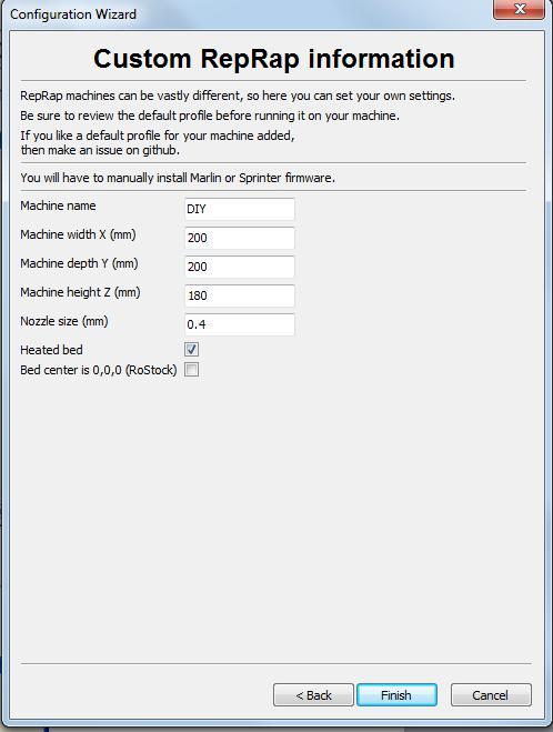
33 Step 5: Start a wizard at the first time Step 6: Select the parameters of the printer, and pay attention on the setting with red box; 31


34 Step 7: Printer setting finished; 32

35 6.4 Install Serial Port Drivers Step 1: Turn on the power of DIY I3, connect the printer with computer by USB cable. Step 2: Select the device manager by right clicking, if there is no suitable serial port driver, a warning with yellow logo in the red box would be occurred as below. Step 3: Right clicking FT232R USB UART, update the driver program, and select Browse my computer for driver software. 33


36 Step 4: Select a suitable driver file to update the driver. Step 5: Please close the window as below after updated. 34
37 Step 6: After driver updated, My computer---device manager is shown as below; 35

38 6.5 On-line Printing Step 1: Double click the icon to start Cura Step 2: Setting the diameter of the line material as 1.75mm, and nozzle as 0.4mm. 36

39 Step 3: Select the first icon to open the folder STL file which needs to be printed., choose the Step 4: Slicing automatically; 37
.")
40 Select the middle icon which means on-line print after slicing; If the middle icon is shown as a saving icon after slicing, please select machine---machine setting to set the port (The port should be considered as the recommendation by computer. For example, the port is COM16 in this instruction case). Step 5: The on-line print in a success, if there is an on-line print window occurred and the word about Print has been switched into boldface. Select Print to heat print head and platform, the print head will return back to the origin of coordinates when the temperature increased to the setting value. Then, the on-line print starts to work. 6.6 Off-line Printing Simple overview: Open the Cura software, import the generated 3D STL file, slice, generate the GCODE format file, save it to the TF card (customer equipped), insert the TF card into the motherboard slot, open the printer, and enter the main page. Select Build From SD, enter the selected print GCODE file, select, wait for the print head, the backplane is heated to the preset temperature, printing starts until the end of the print. 38

41 Step 1: Double-click the icon to open Cura Step 2: Setting the diameter of the line material as 1.75mm, and nozzle as 0.4mm. Step 3: Click the first icon to open the folder, and select the STL file which needs to 39

42 be printed. Step 4: Slicing automatically; Step 5: Select the connection icon in the middle to connect a 3D printer after slicing. Tips: If the middle icon appears after slicing, then, click the middle saving icon. Select saving when the window occurred as below. 40


43 Open the folder into which the printing files needs to be put, copy and paste the file which has been saved before. Step 6: Save the file with the SD card. Turn on the DIY printer, insert the SD card, select Print from SD, then, select the file which has been saved before. Consequently, printing starts and until mission finished. Click the function button, enter into the control function as shown of the LED screen, then, adjust the relative parameters. 41

44 The purpose of the setting, is to adjust the printer head, temperature of base plate and the printing speed. 42
DIY PRINTER INSTALLATION AND OPERATION INSTRUCTION
 CTC DIY PRINTER INSTALLATION AND OPERATION INSTRUCTION Thank you for buying and using DIY 3D printer produced by CTC Please read the installation and operation instruction carefully before use Company
Product User Manual. IdeaWerk 3D Printer WT150
 Product User Manual IdeaWerk 3D Printer WT150 Contents Contents 1. Unpack and checking... 1 1.1 Check the Machine... 1 1.2 Check the Accessories... 3 2. Brief Introduction... 3 2.1 Precautions and Safety...
Dreamer Series User Manual
 Dreamer Series User Manual Welcome to the world of the Dreamer. To ensure that you have the best possible user experience, it s important that you follow this user manual. Let s get started! In Parts I
JGAURORA 3D PRINTER MODEL: A-4 USER GUIDE
 JGAURORA 3D PRINTER MODEL: A-4 USER GUIDE 1 Contents 1. Preface...3 1.1 Introduction...3 1.2 Safety matters... 3 1.3 Filament requirements...3 1.4 Environmental requirements...3 2. About A-4... 4 2.1 Basic
Instruction Manual. RS 3D Printer
 Instruction Manual RS 3D Printer 1) GENERAL This instruction manual contains important information regarding the installation, operation, maintenance and storage for RS 3D Printer. Please read these instructions
Portabee GO. Mobile 3D Printer. Portabee 3D. Romscraj. Software & Support. Manufacturing & Engineering.
 Portabee GO Mobile 3D Printer Portabee 3D Software & Support http://portabee3d.com support@portabee3d.com Romscraj Manufacturing & Engineering http://romscraj.com contact@romscraj.com A. Software Package
think big, print huge
 think big, print huge quick start guide Table of Contents a Receiving and uncrating 5 b bed level & z home 11 c Loading filament 19 d SOFTWARE 23 e Setup 23 f preparing a print 26 g printing on gigabot
Geeetech Duplicator 5 3D printer. User Manual
 Geeetech Duplicator 5 3D printer User Manual Contents Safety Instructions... 4 1.Software Resources... 5 1.1 Repetier-Host... 5 1.2 Driver... 5 1.3 Arduino IDE... 6 2.Connect the Printer... 6 3.Printer
ENJOY Introduction. Software Installation* Hardware. Calibration Settings. Print test. Appendex. Install print S/W Driver Install
 Quick Start Manual 1 ENJOY Introduction C O N T E N T S 6 5 Appendex 4 Print test 3 2 Hardware Calibration Settings Software Installation* Install print S/W Driver Install Hardware Intro Cable installation
English. Quick Guide
 English Quick Guide Specification Product Overview Button and Indicator light Unpacking Accessory Checklist Important Safety Notes Extruder module installation Accessory installation XYZware operation
Operation Instruction
 JGAURORA 3D Printer Model:Z-603S Operation Instruction www.jgaurora3d.com Read it carefully before printing and keep it properly. - 0 - - 1 - Z- 603S model is designed FDM 3d printer by Shenzhen Aurora
Panowin F1. User Manual
 Panowin F1 User Manual 1 PANOWIN TECHNOLOGIES CO.,LTD. WARNING power outlet. CAUTION: In case of emergency unplug the Panowin F1 from the WARNING: Carefully monitor the Panowin F1 during operation. Do
Geeetech Aluminum Prusa I3. User Manual
 Geeetech Aluminum Prusa I3 User Manual 1 Safety Instructions Building the printer will require a certain amount of physical dexterity, common sense and a thorough understanding of what you are doing. We
QUICK START GUIDE ENTER AN ENVIRONMENT OF PROFESSIONAL 3D PRINTING
 QUICK START GUIDE ENTER AN ENVIRONMENT OF PROFESSIONAL 3D PRINTING MEET THE ZORTRAX M200 Zortrax M200 3D printer transforms virtual projects into three-dimensional reality. It is used to prototype and
ZHEJIANG FLASHFORGE 3D TECHNOLOGY CO., LTD. Creator Pro Start-up Guide
 www.ff3dp.com ZHEJIANG FLASHFORGE 3D TECHNOLOGY CO., LTD. Creator Pro Start-up Guide www.ff3dp.com Contents 1 What's Included in the Box? 2 2 Un-boxing 2 3 Initial Hardware Installation 6 4 Software Installation
Runtime Environment: Relative Humidity: 30%~90% Temperature Ranges : 5 ~35
 Product Data sheet IdeaWerk 3D Printer ENGLISH Runtime Environment: Relative Humidity: 30%~90% Temperature Ranges : 5 ~35 Technical Parameters: 1. Electrical Parameters Power Input: AC 100-240V 47/ 63Hz
Instruction Manual. Model RBA18
 Instruction Manual Model RBA18 The Robo-Arm Kit for Arduino is designed to teach the following: 1. How to build a mechanical arm, piece-by-piece. 2. Basic workings of mechanical arm 3. Coding and control
Written By: Josef Prusa
 6. Preflight check The last things you should check before the first print Written By: Josef Prusa 2018 manual.prusa3d.com/ Page 1 of 13 Step 1 P.I.N.D.A. adjustment, phase 1 Ensure the printer is turned
M2 3D Printer V4 M2 3D Printer
 M2 3D Printer V4 Contents 2 Important Safeguards 3 Welcome 4 M2 Features 6 Other products included with your printer 7 Set up 9 Slicing.STL or.obj files 10 Maintenance and Support 11 Warranty 12 About
GEEETECH. Me Creator2 printers contain heated moving parts. Never reach inside the printer while it is in operation or before it has cooled down.
 ME CREATOR 2 SAFETY INSTRUCTION Do read all the instructions and cautionary markings in this manual before operating your Me Creator. Me Creator2 printers contain heated moving parts. Never reach inside
SHENZHEN GETECH TECHNOLOGY CO., LTD. Geeetech A10 3D Printer. User Manual (V2.0)
") Geeetech A10 3D Printer User Manual (V2.0) 1 Content 1 Attention... 3 1.1 Safety instruction... 3 1.2 Factory test before delivery... 3 2 Printer display... 4 3 Assembling... 7 3.1 Assembling the main
Geeetech A10 3D Printer User Manual (V2.0) 1 Content 1 Attention... 3 1.1 Safety instruction... 3 1.2 Factory test before delivery... 3 2 Printer display... 4 3 Assembling... 7 3.1 Assembling the main
da Vinci Super Quick Guide da Vinci Super Safety Precautions Product instructions Unboxing and Installation Product specification
 September. 2017 da Vinci Super Quick Guide ENG Safety Precautions Product instructions Unboxing and Installation Product specification Function Operation and Instructions Setting Print Supporting information
Please carefully read the safety instructions before get started.
 Safety Instructions Please carefully read the safety instructions before get started. ANYCUBIC 3D printer generates high temperature. Do not reach inside of the printer during operation. Allow time for
SeeMeCNC Guides 2 INTO 1 DUAL FILAMENT FEED ADAPTER INSTALL
 SeeMeCNC Guides 2 INTO 1 DUAL FILAMENT FEED ADAPTER INSTALL These are still in development - Be ready to troubleshoot firmware/software configuration for your setup when purchasing these adapters. Written
Cura - DUET Dual Extrusion Setup
 SeeMeCNC Guides Written By: SeeMeCNC 2018 seemecnc.dozuki.com/ Page 1 of 15 INTRODUCTION Please note that dual extrusion is for advanced users. You should have some advanced knowledge on some G-Code and
RS-FX-N01 wind transmitter user's Guide (485type)
") RS-FX-N01 wind transmitter user's Guide (485type) Issue:. V1. 0 1 2 Context 1. Introduction...4 2. Installation instructions... 5 3. Configure the software installation and use...7 4. Communication Protocol...
RS-FX-N01 wind transmitter user's Guide (485type) Issue:. V1. 0 1 2 Context 1. Introduction...4 2. Installation instructions... 5 3. Configure the software installation and use...7 4. Communication Protocol...
RS-FS-N01 Wind speed transmitter user's Guide (485type)
") RS-FS-N01 Wind speed transmitter user's Guide (485type) Issue: V1.0 1 2 Context 1. Introduction... 4 2. Installation instructions...5 3. Configure the software installation and use... 6 4. Communication
RS-FS-N01 Wind speed transmitter user's Guide (485type) Issue: V1.0 1 2 Context 1. Introduction... 4 2. Installation instructions...5 3. Configure the software installation and use... 6 4. Communication
Removal and Installation8
 8 Screw Types 8-4 Top Cover Assembly 8-5 Left Hand Cover 8-6 Right Hand Cover 8-10 Front Panel Assembly 8-14 Left Rear Cover 8-15 Right Rear Cover 8-16 Extension Cover (60" Model only) 8-17 Media Lever
Replacing the TFM coupler
 Repair manual Replacing the TFM coupler Instructions The TFM coupler is a key component of the hot end. It allows filament to flow smoothly through it from the Bowden tube and towards the nozzle. The coupler
Model: 3-Axis High Quality Self-Assembled 3D Printer Kit. Panowin F1
 ESTIMATE No.: Client: Telephone: E-mail: Address: City, State: Contact: Cell-Phone: Fax: Zip Code: Country: Panowin Technologies Co., Ltd. Model: 3-Axis High Quality Self-Assembled 3D Printer Kit Panowin
Ender 3 Series 3D Printer Quick Start Guide
 Ender 3 Series 3D Printer Quick Start Guide This guide is for the Ender 3 Series of 3D printers. Select the correct input voltage to match your local mains (220V or 110V) Because of software/hardware upgrades
ideamaker Manual
 ideamaker Manual Using ideamaker... 2 Basic information... 2 What is ideamaker?... 2 Where to download ideamaker?... 2 Install ideamaker... 3 Let s Print!... 6 How to use ideamaker?... 23 Interface...
MostFun Sail Getting Started V Chengdu MostFun S&T Co.,Ltd.
 MostFun Sail Getting Started V0.96.3 Chengdu MostFun S&T Co.,Ltd. Catalog Product introduction... 2 Parameter...2 The first use of the machine...3 Unboxing... 3 Driver installation... 5 Installing driver
Cutter Option Installation Instructions
 This kit includes the parts and documentation necessary to install the cutter option on the Zebra XiII, XiIII, and XiIIIPlus-Series printers. NOTE: The Cutter Option is not available for the 96XiIII. Adding
SHENZHEN GETECH TECHNOLOGY CO LTD. Geeetech A10M 3D Printer. User Manual (v2.0)
") Geeetech A10M 3D Printer User Manual (v2.0) 1 Content 1 Attention... 3 1.1 Safety instructions... 3 1.2 Factory test before delivery... 3 2 Printer display... 4 3 Assembling... 7 3.1 Assembling the main
Geeetech A10M 3D Printer User Manual (v2.0) 1 Content 1 Attention... 3 1.1 Safety instructions... 3 1.2 Factory test before delivery... 3 2 Printer display... 4 3 Assembling... 7 3.1 Assembling the main
Replacing the Encoder Strip
 6-1-11. Replacing the Encoder Strip The following describes the procedure for replacing the Encoder Strip. Refer to the diagram below for identifying the parts and their positions. (The numbers shown in
MAKERGEAR USER GUIDE. V4 Rev. E Made in the USA since 2009
 MAKERGEAR USER GUIDE M2 V4 Rev. E Made in the USA since 2009 Contents 1 - Welcome 2 - Warning & Important Safeguards 4 - What's Included 5 - Set Up 8 - Slicing.STL or.obj Files 10 - Changing Filament 11
Quickstart Guide Kora Pro 3D PC Printer
 Quickstart Guide Kora Pro 3D PC Printer 1 Rev001/01/2018 Kora Pro PC General Precautions and Advice Only use original accessories from or approved by the manufacturer Always read the manual before initial
3D Prototyping X1 3D Printer. User Manual V1.3
 3D Printer User Manual V1.3 COPYRIGHT This document is copyrighted and contains proprietary information that is the property of 3D Prototyping Pty Ltd. The user does not have the right to copy, reproduce,
Well Link Industries Limited
 Well Link Industries Limited 3D Printing 3D printing is no longer a science fiction. It helps to change from prosthetics and regenerative medicine to structures in space. In 2013, second term State of
M2 3D Printer V4 Rev. D
 M2 3D Printer V4 Rev. D Contents 2 Important Safeguards 3 Welcome 4 M2 Features 6 Other products included with your printer 7 Set up 9 Slicing.STL or.obj files 10 Maintenance and Support 11 Warranty 12
300 DIY 3D PRINTER KIT
 300 DIY 3D PRINTER KIT 1. VERSIONS...2 2. FIRST CHECKS BEFORE TURNING B2X300 ON...3 2.1 PARALLELISM BETWEEN LINEAR GUIDES IN Z...3 2.2 PARALLELISM BETWEEN LINEAR GUIDES IN Z AND TRAPEZOIDAL THREADED RODS...4
Written By: Jakub Dolezal
 5. Preflight check Written By: Jakub Dolezal 2018 manual.prusa3d.com/ Page 1 of 17 Step 1 P.I.N.D.A. adjustment (part 1) Ensure the printer is turned off and not plugged in. Note your extruder is slightly
Technical Support: CUBE USER MANUAL
 CUBE THE DESKTOP 3D PRINTER USER MANUAL 2012-12-05 1 Contents 1 Installing software...3 1.1 Installing Python... 3 1.2 Installing ReplicatorG... 5 2 Pre-print checks...9 2.1 Power up...9 2.2 Connect to
Calibration and Maintenance
 Epson DX5 X 1 Printhead Calibration and Maintenance 31 st Jan., 2013 Version V3.0 1 Contents Chapter 1: Computer Requirement...3 Chapter 2:Installation...4 Chapter 3:Characteristic...5 Chapter 4:Board
3D BIO-PRINTER. USER MANUAL Version D Cultures
 3D BIO-PRINTER 3D Cultures USER MANUAL Version 2.0 Product pictures are for reference only. Color(s), size, parts, and interface may vary. Preheating is not recommend with the use of cells. This manual
TOP - 1. Instruction Manual. Version 1.0 Produced in Jan. 2004
 Version 1.0 Produced in Jan. 2004 Instruction Manual LCD monitor IV-08MP Thank you for purchasing the SHARP IV-08MP LCD monitor. Read this introductory instruction manual carefully to thoroughly familiarize
4. Using Cura to Set Up Your Auto-Leveling Probe and Create Your First Print
 4. Using Cura to Set Up Your Auto-Leveling Probe and Create Your First Print Give a short summary. Written By: Printrbot Support INTRODUCTION Outline what you are going to teach someone how to do. 2015
da Vinci Jr.1.0 April 2016 da Vinci Junior 1.0w 3D Printer da Vinci Jr.1.0w Quick Guide HD23F1JW0N1
 da Vinci Junior 1.0w 3D Printer w Quick Guide P 1 Product Overview A: Filament movement area B: Feed module C: Detector D: Extruder E: Filament F: Print bed G G: SD card port (Storage format: FAT32) H:
Print Mechanism Maintenance Kit
 Print Mechanism Maintenance Kit Installation Instructions This kit includes the parts and documentation necessary to install the print mechanism maintenance kit in the following printers: ZT0 ZT0 ZT0 Read
da Vinci 1.0 Pro Quick Guide
 US da Vinci 1.0 Pro Quick Guide Product Description Print Parameters Description Support Details Product Model: da Vinci 1.0 Professional da Vinci 1.0 Pro Product Description Product Overview Cartridge
DOT MATRIX PRINTER SP6000 SERIES
 DOT MATRIX PRINTER SP6000 SERIES Hardware Manual < Approval: CEL > Trademark acknowledgments SP6000 : Star Micronics Co., Ltd. Notice All rights reserved. Reproduction of any part of this manual in any
Cura (Documentation for version )
") Cura (Documentation for version 15.04.06) Getting Started Installation To start the installation of Cura, download it first. After downloading, open the installer and run the installation wizard to complete
Cura (Documentation for version 15.04.06) Getting Started Installation To start the installation of Cura, download it first. After downloading, open the installer and run the installation wizard to complete
Assembly and Setup Manual
 M-12 Series Copyboard / C-12 Series Captureboard Assembly and Setup Manual This is the installation and assembly manual for the M-12 series Copyboard and C-12 series Captureboard. (The copyboard and/or
Documentation version Prusa i3 Rework USER GUIDE REV 1.5. Document Version 1.1.8
 Documentation version 1.1.8 Prusa i3 Rework USER GUIDE REV 1.5 2 INTRODUCTION Target : Prupose a visual guide of the differents steps to build and use a Prusa i3 Rework. Authors of this document : emotion
USER MANUAL Resolution 0.02mm Speed 300mm/second Software: Wanhao Maker
 1 Duplicator 5S & 5S MINI Desktop 3D Printers USER MANUAL Resolution 0.02mm Speed 300mm/second Software: Wanhao Maker 2014/2015 Wanhao USA 3 Table of Contents Welcome 1 Printer Specifications 2 Unboxing
SPARE PARTS & HOW TO HANDLE. μ-icc 2.45 compact. - Instructions - S/N: A01-PG10-SPE Version No.: 0 V
 SPARE PARTS & HOW TO HANDLE μ-icc 2.45 compact - Instructions - S/N: A01-PG10-SPE Version No.: 0 V1 2010-08-27 1 Introduction... 2 2 Safety instructions... 2 3 Open the housing... 3 4 Constituent parts
Geeetech A10M. Desktop 3D Printer USER MANUAL
 Geeetech A10M Desktop 3D Printer USER MANUAL Terms Please be advised of the following terms (the Terms ) regarding this User Manual (this Manual ): All information in this Manual is subject to change at
Assembly and Setup Manual
 M-11 Series Copyboard/C-11 Series Captureboard Assembly and Setup Manual This is the installation and assembly manual for the M-11 series/c-11 series. To the Customer Specialized techniques are required
Troubleshooting Manual
 Troubleshooting Manual Please be aware of these options as follows : 1. Mainboard is sensitive to static electricity. Please Touch a grounded object to release static electricity before operation. 2. Please
USING YOUR BIGBOT. 1/18/2017 V0.1
 USING YOUR BIGBOT www.bigbot-3d.com 1/18/2017 V0.1 FOREWORD: YOUR PRINTER IS REPRAP, WHICH STANDS FOR "REPLICATING RAPID PROTOTYPERS". THIS MEANS IT CAN PRINT THE PARTS THAT ARE CUSTOM FOR THIS MACHINE,
Installation User Manual
 Edition: C20150105A Installation User Manual *This installation manual is for models: double-printheads inkjet printer, multi-printheads inkjet printer, ueven surface printer and egg printing inkjet printer.
ATTENTION: OBSERVE PRECAUTIONS FOR HANDLING ESD-SENSITIVE DEVICES
 15 Monitor Removal 1. Turn off and unplug the game. 2. Place something in front of the game to brace the bezel once the strain relief cord is undone, then unlock and open the CPU section. 3. Remove the
M40 Microscope User s Manual
 M40 Microscope User s Manual for M40 and M40RT Microscope Components: Trinocular Port Eyepieces Beam Splitter Field Diaphragm Adjustment Aperture Diaphragm Adjustment Filter Slots Analyzer Polarizer Hex
Plasma Panel Replacement Guide DU-42PX12X
 Plasma Panel Replacement Guide DU-42PX12X Panel Replacement: At this point, the panel has been determined to be defective and replacement is necessary. Upon receiving the replacement panel, it must be
PHOS 20/40 downlight OWNER'S MANUAL
 PHOS 20/40 downlight OWNER'S MANUAL TABLE OF CONTENTS Safety Instructions...4 Electrical Safety... 4 Lamp Safety...4 Burns and Fire Safety... 5 Safety During Installation And Operation... 5 Technical Overview...
Control Box Setup - PRSalpha
 888-680-4466 ShopBotTools.com Control Box Setup - PRSalpha Copyright 2016 ShopBot Tools, Inc. page 1 Copyright 2016 ShopBot Tools, Inc. page 2 Parts List: Hooking Up a PRSalpha Gantry Tool Powering the
VJ-1304 INSTALLATION MANUAL
 Please read this manual before using Thank you for purchasing a MUTOH product. This manual explains the steps for unpacking, mounting and basic installation before using the MUTOH Full-color inkjet printer
Axiomet AXB Safety instructions
 Axiomet AXB350 1. Safety instructions Failure to follow the instructions listed below may result in electric shock or personal injury. Please read this manual carefully and thoroughly before using this
MUTOH EUROPE N.V. Tel.:32-(0) Fax:32-(0)
 Fax:32-(0)") MUTOH INDUSTRIES LTD. Tel.:8-(0)-570-00 Fax:8-(0)-570-00 E-mail:ibd@mutoh.co.jp http://www.mutoh.co.jp MUTOH AMERICA INC. Tel.:-80-968-777 Fax:-80-968-7990 E-mail:sales@mutoh.com http://www.mutoh.com MUTOH
MUTOH INDUSTRIES LTD. Tel.:8-(0)-570-00 Fax:8-(0)-570-00 E-mail:ibd@mutoh.co.jp http://www.mutoh.co.jp MUTOH AMERICA INC. Tel.:-80-968-777 Fax:-80-968-7990 E-mail:sales@mutoh.com http://www.mutoh.com MUTOH
CAMERA ASSEMBLY. Removal/Replacement of the Camera Box Assembly APR-CA. Install Camera Assembly. Remove Camera Assembly
 CAMERA ASSEMBLY Removal/Replacement of the Camera Box Assembly APR-CA REQUIRED TOOLS: 9/64 hex key Small flat-tip screwdriver Remove Camera Assembly camera 1. Locate the camera assembly underneath the
Makeblock Constructor I 3D Printer Kit. 2. 3D Printer Wiring Guide
 2. 3D Printer Wiring Guide 1 Content 2.1. Parts Required... 3 2.2 preparation... 7 2.2.1 Add heat sinks on the top of stepper motor driver chip... 7 2.2.2 Plug the jumper cap into corresponding position...
E3 CNC Router Troubleshooting Guide
 Simple Cost Effective Designs. E3 CNC Router Troubleshooting Guide The purpose of this document is to give those new to CNC routing is a quick reference for the common issues of getting the E3 CNC router
VJ-1618 INSTALLATION MANUAL
 Please read this manual before using Thank you for purchasing a MUTOH product. This manual explains the steps for unpacking, mounting and basic installation before using the MUTOH Full-color inkjet printer
Vector 3D printer complete wire list including extruder PWA listing
 Vector 3D printer complete wire list including extruder PWA listing Conventions Pin numbering for connectors It is normal practice in print circuit board (PCB) layout to denote pin 1 of a PCB mounted connector
LED Maintenance Instructions
 Chapter 5 LED Maintenance Instructions This guide describes the maintenance procedures for the LED portion of your DayStar or TekStar sign. 1.800.237.3928 stewartsigns.com Rev1802 Intentionally Left Blank
Agenda. Breaking the Ice Physical Setup Walkthrough of REPETREL First Print
 T1 Training Session Agenda Breaking the Ice Physical Setup Walkthrough of REPETREL First Print Breaking the Ice SYSTEM 30M ENGINE Breaking the Ice Protected build environment Slightly larger build area
Software Manual. Revision 1.3
 Software Manual Revision 1.3 Copyright 2015 by Kudo3D. This material may be distributed only subject to the terms and conditions set forth in the Creative Commons Attribution-NonCommercial-NoDerivatives
Lightning Stitch Assembly
 ABM International, Inc. 1 1.0: Parts List Lightning stitch motor and drive assembly (Qty. 1) Lightning stitch piggy backed controller board assembly (Qty. 1) Touchscreen (Qty. 1) 2 9-pin Serial cable (Qty.
Portal Delta Pro 3D printer
 Portal Delta Pro 3D printer User s Manual v1.0 Welcome to the world of 3D printing! Thank you for your purchase of the Mass Portal 3D printer we hope that it will serve you well and even exceed your expectations.
Megatouch FORCE Monitor Chassis Board Replacement
 Megatouch FORCE Monitor Chassis Board Replacement Visit the Merit Industries, Inc. Web site http://www.meritind.com merit industries, inc. PM0337-01 Rev C Table of Contents FORCE Classic Monitor Chassis
TRC-190 User s Manual
 User s Manual Edition 3.2, May 2017 www.moxa.com/product 2017 Moxa Inc. All rights reserved. User s Manual The software described in this manual is furnished under a license agreement and may be used only
3D Printing Getting Started!
 ARCHITECTURE & LANDSCAPE ARCHITECTURE 3D Printing Getting Started! White filament is free to students for academic use. Where do I buy filament? NORTH DAKOTA STATE UNIVERSITY www.makerbot.com/store www.ultimachine.com/pla
SERIES 1 USER MANUAL TYPE A MACHINES
 SERIES 1 USER MANUAL TYPE A MACHINES Type A Machines Inc. 2014 Type A Machines Inc. This document is licenced by Creative Commons Attribution-NonCommercial-ShareAlike (CC BY-NC-SA) Users are free to remix,
EQ573 Assembly guide. EQ573 Assembly guide Main board 1. Diodes. 2. Resistors (1) 3. Test pins. 4. Ceramic capacitors.
 3. Test pins. 4. Ceramic capacitors.") EQ573 Assembly guide Safety warning The kits are main powered and use potentially lethal voltages. Under no circumstance should someone undertake the realisation of a kit unless he has full knowledge about
EQ573 Assembly guide Safety warning The kits are main powered and use potentially lethal voltages. Under no circumstance should someone undertake the realisation of a kit unless he has full knowledge about
RS-422/485 PCIe Card
 RS-422/485 PCIe Card User Manual Ver. 3.00 All brand names and trademarks are properties of their respective owners. Contents: Chapter 1: Introduction... 3 1.1 Product Introduction... 3 1.2 Features...
LED SPIDER MOVING HEAD LIGHT
 LED SPIDER MOVING HEAD LIGHT MJ-1031C (4IN1) INSTRUCTION MANUAL Thank you for choosing our LED spider moving head light. For the sake of your safety, Please read and follow these instructions carefully
3d Printing with the Prusa I3 Operation & Printing via a USB Cable
 3d Printing with the Prusa I3 Operation & Printing via a USB Cable Instructions for: Prusa I3 Printer Set-up Slic3r Software Use Pronterface Software Use Prusa I3 - Parts Identification Prusa I3 Printer
RS-422/485 PCI Card User Manual Ver All brand names and trademarks are properties of their respective owners.
 RS-422/485 PCI Card User Manual Ver. 2.00 All brand names and trademarks are properties of their respective owners. Contents: Chapter 1: Introduction... 3 1.1 Product Introduction... 3 1.2 Features...
MEGATRONICS V3.0 QUICK START GUIDE
 MEGATRONICS V3.0 QUICK START GUIDE Thank you for purchasing the Megatronics v3.0! This small guide will answer the basic questions on how to connect the board to your 3D printer. For more information visit
PowerSpec Ultra 3D Printer Start-up Guide Table of Contents
 PowerSpec Ultra 3D Printer Start-up Guide Table of Contents 1 What's Included in the Box?...Page 3 2 Un-boxing.Page 4 3 Initial Hardware Installation Page 6 4 Software Instruction.Page 8 5 Filament Page
INSTALLATION INSTRUCTIONS
 Accessory Application Publication No. INSTALLATION INSTRUCTIONS AUDIO UNIT P/N 08A70-MJN-A00 CTX1300/D MII 14925 Issue Date April 2014 PARTS LIST (11) (8) (2) TOOLS AND SUPPLIES REQUIRED Socket (10 mm)
Installation Manual. Mounting Instructions Mechanical Mounting. Luminato. Teleste Corporation
 Luminato Installation Manual Teleste Corporation Mounting Instructions Mechanical Mounting Luminato Mechanical Installation, agile_59300316, rev0044 Introduction 1 Contents Introduction 4 General... 4
The SC812/SC812L Chassis Series Installation Guide
 SUPER The SC812/SC812L Chassis Series Installation Guide Rev. 1.0 SC812/SC812L Chassis User's Guide Table of Contents Chapter I: Introduction... 1-3 A. Front Panel Connectors... 1-3 B. Front Panel LED
VJ-1614 INSTALLATION MANUAL
 VJ-6 INSTALLATION MANUAL Please read this manual before using Thank you for purchasing a MUTOH product. This manual explains the steps for unpacking, mounting and basic installation before using the MUTOH
Warning Before Installation. Package Contents EN - 1. Refer to your user s manual for the operating temperature.
 5000020G Warning Before Installation English Power off the Network Camera as soon as smoke or unusual odors are detected. Do not place the Network Camera on unsteady surfaces. Do not insert sharp or tiny
Chitu V3.6 User Manual. Compiler:Pitt Xie Date: 01/11/2015 Reviewer:David Yi Date: 01/11/2015 Approver:Sam Lin Date: 01/11/2015
 Chitu V3.6 User Manual Compiler:Pitt Xie Date: 01/11/2015 Reviewer:David Yi Date: 01/11/2015 Approver:Sam Lin Date: 01/11/2015 Copyright Declaration The manual is only used for the purchaser. Any part
ColorMaxLP Label Roll Rewinder
 ColorMaxLP Label Roll Rewinder 5/2017 INSTALLATION/OPERATOR MANUAL Included: Rewinder Base plate Power supply Power Cord Thumb screws Assembly instructions 1. Install base plate Lift front of printer and
* IMPORTANT * REGISTERING YOUR MACHINE
 * IMPORTANT * REGISTERING YOUR MACHINE Thank you for your purchase of the Keyline 994 Laser. Before continuing with machine setup and use, please complete the following; COMPLETE PRODUCT REGISTRATION FORM
E3 CNC Router Troubleshooting Guide
 Simple Cost Effective Designs. E3 CNC Router Troubleshooting Guide The purpose of this document is to give those new to CNC routing is a quick reference for the common issues of getting the E3 CNC router