EX-9686U/A-L(A9) Hardware User Manual
|
|
|
- Valentine Lynch
- 5 years ago
- Views:
Transcription
1 EX-9686U/A-L(A9) Hardware User Manual
2 Release Notes Version Release Date Notes 1.00 November, 2013 Initial Release 2.00 January, 2014 The 2 nd release Disclaimer This documentation is provided for use with TOPSCCC Technology CO., LTD products. No license to TOPSCCC Technology CO., LTD property rights is granted. TOPSCCC Technology CO., LTD assumes no liability and provides no warranty either expressed or implied relating to the usage or intellectual property right infringement that may result from its use. TOPSCCC provides this document as is, without warranty of any kind, expressed or implied, including, but not limited to, its particular purpose. TOPSCCC Technology CO., LTD may make changes to this document without notice. Page 2
3 Table of Contents TABLE OF CONTENTS PRECAUTIONS Safety Precautions Write Prohibited Regions Warranty PRODUCT FEATURES Overview Features and Specifications INTERFACE SPECIFICATIONS MicroSD Connector UART Connectors & Debug Port USB Connectors Audio Interface Ethernet Interface Power Supply (DC-IN connector) GPIO Pin Header BM Connector Parallel Display Interface Touch Screen Interface LED Reset Switch Expansion Connector EEPROM RTC (Real Time Clock) APPENDIX A: BOX HEADER TO DB9 CABLE...32 APPENDIX B: 5-INCH LCD BRIEF (WVGA)...33 APPENDIX C: METAL FRAME OUTLINE DRAWING...34 Page 3
4 1 Precautions 1.1 Safety Precautions In order to use this product safely, please take special note of the following precautions. Read all product manuals and related documentation before using this product. Use this product correctly and safely. Follow all warnings. If operating or extending this product in a manner not described in this manual, please do so at your own risk. Be sure to fully read this manual and other technical information on our website and proceed safely and responsibly. Do not install this product in a place with a lot of water, moisture, dust or soot. This could cause product failure, fire, or an electric shock. Some parts of this product generate heat and can reach high temperatures. This may cause burns if it is improperly handled. Do not touch the electronic components or surrounding area while powered on or immediately after being turned off. Carry out any design and development only after you have thoroughly read and understood this manual and any other related technical materials on the website or in the data sheets. Test your product thoroughly for reliability and safety. This product is not intended for applications that require extremely high reliability, safety, functionality and accuracy: including but not limited to medical equipment, traffic control systems, combustion control systems, and safety equipment. This company is not liable for death or injury if used in such systems. This product uses semiconductor components designed for generic electronics equipment such as office automation, communications, measurement equipment and machine tools. Foreign noise or a power surge may cause this product to malfunction or fail. To ensure there is no risk of bodily harm or property damage, be sure to take all electrical safety precautions such as protection circuits, limit switches, fuse breakers, or redundant systems. Only use the device after sufficient reliability and safety measures are in place. Page 4
5 1.2 Write Prohibited Regions Data stored by the EEPROM, i.mx6q/d electrical fuse (e-fuse) is used by the software contained in this product. Do not write to these regions as this may cause the product stop working correctly. Purposely writing to these regions voids the product warranty. 1.3 Warranty As described in the Product Warranty Policy provided with this product, the main board is covered by a one year replacement warranty starting from the time of purchase. Please note that the other included goods and software are not covered under this warranty. Some knowledge used by TOPSCCC Technology CO., LTD is provided by third parties, and TOPSCCC Technology CO., LTD. makes no representation or warranty as to the accuracy of such information. Page 5
6 2 Product Features 2.1 Overview The EX-9686U/A-L(A9) is a Freescale imx6 ARM Cortex-A9 based embedded for Gigabit Ethernet ; Micro SD card socket ; USB 2.0 host connector x2 ; USB 2.0 OTG connector x1 ; RS232 x1 and RS485x1 ; GPIO (8-bit) ; IEEE b/g/n Wi-Fi x 1(Optional). It is a flexible, high performance and inexpensive platform designed for embedded applications such as communication/ home/ building/ factory automation. Each device can be installed in advance with Windows Embedded Compact 7, Ubuntu or Android 4.2 for immediate evaluation. Page 6
7 2.2 Features and Specifications Freescale imx6 ARM Cortex -A9 single 1 GHz (imx6 Solo) 1GB DDR3 SDRAM 4GB emmc Flash Hardware Video Decoder Support 10/100/1000 Mbps Gigabit Ethernet interface RJ-45 connector x1 Single parallel 24-bit display port(ttl LCD) x1(internal) Resistive/ Capacitive touch port x1(internal) +5V DC power input connector x1 USB 2.0 host connector x2 USB 2.0 OTG connector x1 Micro SD card socket x1 SGTL5000 Audio Codec, Amplifier circuit MIC-in connector x1(internal), Earphone connector x1(internal) Speaker connector x2 (L/R) DB9 connector x2 (RS232 x1 and RS485x1) Debug (Console) Port: 8-pin header x1 (optional debug cable is required) GPIO (8-bit) pin header x1(internal) IEEE b/g/n Wi-Fi x 1 (Optional) PCB Dimension: 72mm x 120mm Page 7

8 3 Interface Specifications The following photos show connector positions on the EX-9686U/A-L(A9) product. The functional details of the connectors are described in subsequent sections. PCB Top View J1: GPIO USB OTG MicroSD Ethernet Reset D6/D7: LED CN2: Debug / Console J4: BM CON3: RS485 JP1: Headphone CON4: RS232 JP3: MIC-IN JP2: Line-IN JP4: 5V-out CON1: Speaker R CON2: Speaker L CN5: USB Host x 2 J6: USB Host J8: USB Host J7: DC-IN J5: DC-IN Page 8


9 PCB Bottom View HC1: EXT Bus HC2: EXT Bus CN6: LCD J9: CTP CN7: RTP Page 9
10 3.1 MicroSD Connector The microsd host connector has the following specification: SD Host Controller Standard Specification version 3.0 MMC System Specification version 4.2/4.3/4.4 SD Memory Card Specification version 3.0 and supports the Extended Capacity SD Memory Card SDIO Card Specification version 3.0 microsd Connector Pin-out Pin Signal Pin Signal 1 Data 2 6 GND 2 Data 3 7 Data 0 3 CMD 8 Data 1 4 VDD 9 CD 5 CLK Page 10
11 3.2 UART Connectors & Debug Port There are 3 UART ports on this device. The connector type and functions are described in the table below: UART Number Connector Type Available Signals Notes UART1 1x5 header CMOS signal level Console/Debug port. (CN2) (TX, RX) A separate debug cable is required. UART2 DB9 RS232 signal level RS232 port (CON4) (TX, RX, RTS, CTS) UART3 DB9 RS485 signal level RS485 port (CON3) (485+, 485-) Note: RS485 port works only in HALF Duplex mode CON3: UART3 RS485 CN2: UART1: Debug / Console CON4: UART2 RS232 Page 11
 UART1 is dedicated as the debug or console port.")
12 DB9 Male Connector DB9 2x4 RS232 RS485 Pin header RxD TxD GND GND RTS CTS DB9 Female Connector UART1 Connection Diagram: EX-9686U/A -L(A9) UART1 is dedicated as the debug or console port. The default communication settings are Baud Rate , 8 data bits, no parity, 1 stop bit and no flow control. Note that UART1 is at CMOS signal level. There is no RS232 transceiver on the port. A separate debug cable is required to connect UART1 to a PC terminal. A DB9 null modem cable (or adapter) is required when you want to connect UART1 to a PC with terminal emulation software such as TeraTerm. Page 12
13 UART2 Block Diagram: imx6 CPU TX, RX RTS, CTS RS232 Transceiver DB9 Connector UART2 (with TX, RX, RTS, CTS signals) works as a regular RS232 port. UART3 Connection Diagram: imx6 CPU ZT485E DB9 Connector ZT485E: RS485 transceiver. RS485 works in half duplex mode. Page 13

14 3.3 USB Connectors The USB interfaces on EX-9686U/A-L(A9) include a USB 2.0 OTG port and four USB2.0 host ports. Speed of up to 480 Mbps supported. The USB 2.0 host interface is connected to a hub controller to extend host ports. Two of the USB2.0 hub ports are available in type A connectors for users. The other two USB ports are available in pin-headers reserved for WiFi module or other devices. USB Port: USB2.0 OTG USB2.0 OTG Connector imx6 CPU USB2.0 Host 4-port Hub USB2.0 Connectors (type A) USB2.0 (J8 header for WiFi) USB2.0 (J6 header for other) NOTE: The USB 2.0 OTG can be used in host mode or device mode. If you would like to use it in host mode, a separate OTG-to-host cable is required. The USB 2.0 host connector is a regular USB type A connector that can be connected to +5V USB storage device. This port is mainly used to connect to USB flash drive. Pin Signal Pin Signal 1 5V 1 5V 2 Data - 2 Data - 3 Data + 3 Data + 4 GND 4 ID 5 GND Page 14
15 USB port 2 is connected to J6 pin header. USB port 3 is connected to J8 pin header and is reserved for b/g/n WiFi module. Page 15
16 3.4 Audio Interface The audio interface is implemented by a SGTL5000 audio codec. The data and control interface between CPU and SGTL5000 is I 2 S. Connector Number CON1 CON2 JP3 JP1 JP2 Part Description Speaker Right Speaker Left MIC-IN Headphone Out Line-IN Audio Interfaces: Amplifier Speaker imx6 CPU I 2 S Audio Codec Head Phone (out) MIC (in) Headphone header MIC-in header Line-in header Speaker Page 16
17 Page 17
18 3.5 Ethernet Interface The 10/100/1000 Mbps Gigabit Ethernet interface is available with a standard RJ-45 connector. Ethernet: imx6 CPU Ethernet PHY RJ-45 Connector Page 18

19 3.6 Power Supply (DC-IN connector) +5V Power input can be applied to the J7 DC jack or to the 2-pin header J5. The JP4 header can be connected to an LED as the indicator of power input. Page 19
. The GPIO pins are available on J1 pin header.")
20 3.7 GPIO Pin Header The GPIO pin header provides user to connect up to 8 GPIO devices (+3.3V signal level). The GPIO pins are available on J1 pin header. J1 pin 1 Page 20
21 GPIO pin assignment: J1 pin # GPIO # J1 pin # GPIO # For more information about programming GPIO, please refer to a separate document: Application Note GPIO. Page 21
22 3.8 BM Connector The J4 connector is used to select the operation mode: Normal Operation mode or Firmware Download mode. For more information about Firmware Download mode (to burn firmware image), please refer to Firmware Image Download application note. J4 pin 1 Firmware Download: Pin 1, 2 open Pin 3, 4 short J4 pin 1 Normal Operation: Pin 1, 2 short Pin 3, 4 short J4: BM pin1 Page 22
23 3.9 Parallel Display Interface The parallel display interface (CN6) is a 40-pin connector designed to use with a x272 LCD or 5 800x480 LCD. Other size and resolution of LCDs can also be used with this interface with proper signal connection. Page 23
24 Most of the interface pins are connected directly to imx6 processor pins. For the electrical DC/AC parameters of the pins, please refer to Freescale imx6 processor data sheet. CN6 Pin 1 Page 24
25 3.10 Touch Screen Interface CN7 is for connecting to a 4-wire resistive touch screen: J9 can be used for capacitive touch screen or touch pad interface. In addition to +5V and +3.3V power pins, two GPIO for interrupt, reset and one I2C master port for data are on the connector. J9: Pin 1 CN7: Pin 1 Page 25
26 3.11 LED D6 and D7 LEDs are connected to GPIOs for customer application software to use them. Please check with us to make sure the device driver is already available for application software to turn on/off LEDs. D6/D7: LED Page 26
27 3.12 Reset Switch SW1 Reset switch is for system reset. SW1: RESET Page 27
 LVDS, MIPI, Camera interface, I2C, SD card, GPIO,etc.")
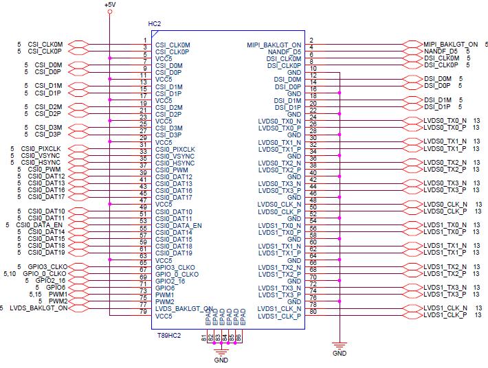
28 3.13 Expansion Connector HC1 and HC2 connectors are for connecting to expansion board to realize more imx6 functions. The interfaces on HC1 and HC2 include (but is not limited to) LVDS, MIPI, Camera interface, I2C, SD card, GPIO,etc. Contact us for more details when you plan to use the interfaces on HC1 or HC2. Page 28
29 Page 29
30 3.14 EEPROM A 4Kx8bit (32K-bit) non-volatile eeprom is mounted on board to keep system data. Part of the storage is available for user to store application data. The eeprom data read/write is done by imx6 I2C channel 1. A device driver in Android and Linux is available for application software to read/write eeprom data. Page 30
31 3.15 RTC (Real Time Clock) The RTC is implemented by a DS1307 real time clock chip connected to imx6 I2C channel-1. A chargeable coin battery (3V/5mAh) is mounted on board to keep RTC in normal operation when system power is off. Page 31
32 Appendix A: Box Header to DB9 Cable Page 32
33 Appendix B: 5-inch LCD Brief (WVGA) General Specifications Item Specification LCD Size 5.0 inches Driver Element a-si TFT active matrix Display Resolution 800 x 3 (RGB) x 480 Display Mode Normally white, Transmissive Dot Pitch 0.360(W) x 0.360(H) mm Active Area (W) x 64.80(H) mm Module Size (W) x 75.80(H) x 4.20(D) mm (* including touch screen *) Surface Treatment Anti-glare(AG) Pixel Arrangement RGB-Stripe Display Color 16.7M Input Interface Digital RGB Absolute Maximum Ratings Item Symbol Min Max Unit Power Voltage Vdd V Storage Temperature T ST Operating Temperature T OP LED Forward Current I F - 25 ma o C o C Optical Characteristics Item Symbol Typical Unit Luminance L 250 cd/m 2 Contrast Ratio CR Page 33
34 Appendix C: Metal Frame Outline Drawing Page 34
Release Notes Version Release Date Notes 1.20 October 1 st, 2013 The 2nd release to customer 1.30 October 30 th, 2013 Add more interfaces info Disclai
 SBC21/NSD21/EC21 Series Hardware User Manual Release Notes Version Release Date Notes 1.20 October 1 st, 2013 The 2nd release to customer 1.30 October 30 th, 2013 Add more interfaces info Disclaimer This
SBC3100 (Cortex-A72) Single Board Computer
 Single Board Computer") (Cortex-A72) Single Board Computer Ultra High Performance SBC with RK3399 (Cortex-A72 x2 + Cortex-A53 x4) @ 2Ghz : Single Board Computer H310: Input (receiver) Module : Output (display) Module D120: 4xCOM
(Cortex-A72) Single Board Computer Ultra High Performance SBC with RK3399 (Cortex-A72 x2 + Cortex-A53 x4) @ 2Ghz : Single Board Computer H310: Input (receiver) Module : Output (display) Module D120: 4xCOM
Quick Start Guide EX-9686U/A-L(A9) Copyright TOPSCCC Technology CO., LTD. All rights reserved
 Copyright TOPSCCC Technology CO., LTD. All rights reserved") Quick Start Guide Copyright 2000 2014 TOPSCCC Technology CO., LTD. All rights reserved Release Notes Version Release Date Notes 1.0 June 2013 Initial release 2.0 October 2013 Correct some typo errors 3.1
Quick Start Guide Copyright 2000 2014 TOPSCCC Technology CO., LTD. All rights reserved Release Notes Version Release Date Notes 1.0 June 2013 Initial release 2.0 October 2013 Correct some typo errors 3.1
IB112. Freescale I.MX536 ARM Cortex -A8 Embedded BOARD. USER S MANUAL Version 1.0
 IB112 Freescale I.MX536 ARM Cortex -A8 Embedded BOARD USER S MANUAL Version 1.0 Acknowledgments Freescale is a registered trademark of Freescale Semiconductor Inc. All other product names or trademarks
MYD-IMX28X Development Board
 MYD-IMX28X Development Board MYC-IMX28X CPU Module as Controller Board Two 1.27mm pitch 80-pin SMT Connectors for Board-to-Board Connections 454MHz Freescale i.mx28 Series ARM926EJ-S Processors 128MB DDR2
BYARM-181-PC. User Manual
 www.ibase.com.tw BYARM-8-PC User Manual IBASE Technology Inc. BYARM-8-PC User Manual 2 Revision Release Date V0. 205/02/03 Copyright 203 IBASE Technology Inc. All Rights Reserved. 2 BYARM-8-PC User Manual
MYD-IMX28X Development Board
 MYD-IMX28X Development Board MYC-IMX28X CPU Module as Controller Board Two 1.27mm pitch 80-pin SMT Male Connectors for Board-to-Board Connections 454MHz Freescale i.mx28 Series ARM926EJ-S Processors 128MB
SABRE Board for Smart Devices
 Quick Start Guide SABRE Board for Smart Devices Based on the i.mx 7Dual Applications Processor SMART APPLICATION BLUEPRINT FOR RAPID ENGINEERING (SABRE) Quick Start Guide GET TO KNOW SABRE BOARD FOR SMART
INTERRA I-MINI TOUCHPANEL GENERAL INFORMATION
 INTERRA I-MINI TOUCHPANEL GENERAL INFORMATION INTERRA@2018 GENERAL INFORMATION INTERRA IMINI TOUCHPANEL is an electronic device used in building automation systems. TECHNICAL SPECIFICATION: CPU Memory
SoM-250ES SoM 200-pin Carrier Board User Manual REV. 1.1
 SoM-250ES SoM 200-pin Carrier Board User Manual REV. 1.1 Copyright 2012 EMAC, Inc. Table of Contents Disclaimer... 1 1 SoM-250 Product Summary... 2 1.1 Specifications... 3 2 SoM-250 Product Details...
DATASHEET. MK-070C-HP High Performance 7 Inch Capacitive Touch Display. Amulet. Technologies. July 2015 Revision A
 High Performance 7 Inch Capacitive Touch Display DATASHEET July 2015 Revision A Introduction The MK-070C is the newest family member in the Display Module product line. The new 7 Capacitive Display Module
NSD2100 Smart Display
 NSD2100 Smart Display The ideal platforms for multimedia, digital signage and HMI applications 1200nits High Brightness TFT LCD 5 inch ~ 22 inch, 1920 1080 pixel Resistive and Capacitive 9V ~ 36V Wide
xpico 200 Series Evaluation Kit User Guide
 xpico 200 Series Evaluation Kit User Guide This guide describes how to setup the xpico 200 series evaluation kit and provides the information needed to evaluate the included xpico 240 or xpico 250 embedded
SAMSUNG ELECTRONICS RESERVES THE RIGHT TO CHANGE PRODUCTS, INFORMATION AND SPECIFICATIONS WITHOUT NOTICE. Products and specifications discussed
 SAMSUNG ELECTRONICS RESERVES THE RIGHT TO CHANGE PRODUCTS, INFORMATION AND SPECIFICATIONS WITHOUT NOTICE. Products and specifications discussed herein are for reference purposes only. All information discussed
The Information contained herein is subject to change without notice. Revisions may be issued regarding changes and/or additions.
 Pepper 43R TM Gumstix, Inc. shall have no liability of any kind, express or implied, arising out of the use of the Information in this document, including direct, indirect, special or consequential damages.
SABRE for Automotive Infotainment Quick Start Guide. Smart Application Blueprint for Rapid Engineering Based on the i.mx 6 Series
 SABRE for Automotive Infotainment Quick Start Guide Smart Application Blueprint for Rapid Engineering Based on the i.mx 6 Series About SABRE Platform for Automotive Infotainment Based on the the i.mx 6
VK5100-imx6 Development Platform Quick Start Guide
 VK5100-imx6 Development Platform Quick Start Guide VEST-VK5100-QSG-001 Copyright 2016 Advanced Products Corporation Pte Ltd. All rights reserved. No part of this document may be photocopied, reproduced,
Matrix-700 Linux-Ready Cortex-A5 Industry IoT Gateway Hardware Guide
 Matrix-700 Linux-Ready Cortex-A5 Industry IoT Gateway Hardware Guide Version: 1.12 2018 Jan. Copyright Artila Electronics Co., Ltd. All Rights Reserved. Matrix-700 Hardware Guide Trademarks The Artila
AT-501 Cortex-A5 System On Module Product Brief
 AT-501 Cortex-A5 System On Module Product Brief 1. Scope The following document provides a brief description of the AT-501 System on Module (SOM) its features and ordering options. For more details please
SBC8140 Single Board Computer
 SBC8140 Single Board Computer TI DM3730 Processor based on 1GHz ARM Cortex-A8 core Flexible Design with a Tiny CPU Board mounted on Expansion Board Memory supporting 256MByte DDR SDRAM and 512MByte NAND
LPC1788 Mio Board. User Manual. Revision 1.0 1
 User Manual http://coineltech.com Revision 1.0 1 Designed by CoiNel Technology Solutions LLP No-32, 2 nd Floor, HAPBCO Tower, 9 th Main, RPC Layout, Hampinagar, Bangalore-560040 State: Karnataka Country:
The Information contained herein is subject to change without notice. Revisions may be issued regarding changes and/or additions.
 Pepper DVI TM Gumstix, Inc. shall have no liability of any kind, express or implied, arising out of the use of the Information in this document, including direct, indirect, special or consequential damages.
Item Symbol Absolute Maximum Rating Unit Remarks
 7 TFT LCD asi LCD Color Module The is a compact full color TFT LCD module, that is suitable for portable products, industrial products, hand-held products, security products, instrument displays and office
ARM Quad-Core Embedded Computer
 ARM Embedded Computer Features High-performance Freescale imx6 (ARM Cortex-A9 core) computer @ 1Ghz Rich interfaces, supports, Gb Ethernet, /,, On-board 4GB Flash (emmc) Light weight aluminum enclosure
This product is RoHS compliant PKA1GxxxRx-00R
 This product is RoHS compliant PKA1GxxxRx-00R Specification 2014.8.26 Version 0.5 Features System - ARM Cortex-A8 @ 600MHz - 256 MB LPDDR DRAM / 256 MB NAND Flash - 512 MB LPDDR DRAM / 512 MB NAND Flash
Feature and Benefits. Certifications
 UC-2100 Series Arm-based palm-sized industrial computing platform for IIoT applications Feature and Benefits Armv7 Cortex-A8 1000 MHz processor 1 or 2 auto-sensing 10/100 Mbps Ethernet ports Gigabit Ethernet
The Information contained herein is subject to change without notice. Revisions may be issued regarding changes and/or additions.
 Cobalt MC Gumstix, Inc. shall have no liability of any kind, express or implied, arising out of the use of the Information in this document, including direct, indirect, special or consequential damages.
This product is RoHS compliant PK65VxxxRx-00R
 This product is RoHS compliant PK65VxxxRx-00R Specification 2013-09-06 Version 0.4 Features System - ARM Cortex-A8 @ 600MHz - 256 MB LPDDR DRAM / 256 MB NAND Flash - 512 MB LPDDR DRAM / 512 MB NAND Flash
This product is RoHS compliant PK70WxxxRx-00R
 This product is RoHS compliant PK70WxxxRx-00R Specification 2013.09.06 Version 0.5 Features System - ARM Cortex-A8 @ 600MHz - 256 MB LPDDR DRAM / 256 MB NAND Flash - 512 MB LPDDR DRAM / 512 MB NAND Flash
OnRISC. OnRISC Baltos ir 2110
 OnRISC OnRISC Baltos ir 2110 Hardware Manual Edition: October 2015 Tel: +49 40 528 401 0 Fax: +49 40 528 401 99 Web: www.visionsystems.de Support: service@visionsystems.de The software described in this
The TechNexion Difference
 EDM The TechNexion Difference Faster Time-to-market Through Open Design System on Modules are designed to speed up and reduce the cost of development for embedded devices. But these benefits are only possible,
Quick Start Guide Multisensory Enablement Kit i.mx 8QuadXPlus MEK CPU Board. Based on i.mx 8QuadXPlus Applications Processor
 Quick Start Guide Multisensory Enablement Kit i.mx 8QuadXPlus MEK CPU Board Based on i.mx 8QuadXPlus Applications Processor Quick Start Guide GET TO KNOW THE MEK BASED ON i.mx 8QUADXPLUS APPLICATIONS PROCESSOR
OnRISC Alekto 2 Hardware Manual
 OnRISC Alekto 2 Hardware Manual Edition: September 2013 Tel: +49 40 528 401 0 Fax: +49 40 528 401 99 Web: www.visionsystems.de Support: service@visionsystems.de The software described in this manual is
LeopardBoard Hardware Guide Rev. 1.0
 LeopardBoard with VGA Camera Board LeopardBoard Hardware Guide Rev. 1.0 April 5, 2009 Page 1 LeopardBoard.org provides the enclosed product(s) under the following conditions: This evaluation kit is intended
PV8900-CORE Full Function TCC8900/TCC8901/TCC8902 CPU Module Specification
 PV8900-CORE Full Function TCC8900/TCC8901/TCC8902 CPU Module Specification 1. Overview: PV8900-CORE CPU Module is designed by Shanghai Povell Electronic Technologies Co., Ltd. in 2010, this CPU module
The Information contained herein is subject to change without notice. Revisions may be issued regarding changes and/or additions.
 Poblano 43C TM Gumstix, Inc. shall have no liability of any kind, express or implied, arising out of the use of the Information in this document, including direct, indirect, special or consequential damages.
Quick Start Guide. SABRE Platform for Smart Devices Based on the i.mx 6 Series
 Quick Start Guide SABRE Platform for Smart Devices Based on the i.mx 6 Series Quick Start Guide About the SABRE Platform for Smart Devices Based on the i.mx 6 Series The Smart Application Blueprint for
This product is RoHS compliant PK80SxxxRx-00R
 This product is RoHS compliant PK80SxxxRx-00R Specification 2013-09-16 Version0.5 Features System - ARM Cortex-A8 @ 600MHz - 256 MB LPDDR DRAM / 256 MB NAND Flash - 512 MB LPDDR DRAM / 512 MB NAND Flash
Matrix-710. Linux-Ready Cortex-A5 Industry IoT Gateway. Hardware Guide. Version: Nov.
 Matrix-710 Linux-Ready Cortex-A5 Industry IoT Gateway Hardware Guide Version: 1.01 2017 Nov. Copyright Artila Electronics Co., Ltd. All Rights Reserved Trademarks The Artila logo is a registered trademark
SPECIFICATION APPROVAL SHEET
 SPECIFICATION APPROVAL SHEET FDT Tech Module No.: UC070WIx0x-00R Description: 7 Digital TFT-LCD Module SPEC No.: SAS-1702005 Version: 0.0 Issue Date: February 22, 2017 This approval sheet contains 23 pages
pico-sam9g45 System board
 System board Reference manual Rev. 1.j Layout Views Layout top view Layout bottom view Legend: J2 Ethernet port J12 ZIF connector for the LCD U1 USB HUB SMSC chip J3 USB 2.0 J14 Keypad connector BEEP PWM
Quick Start Guide. i.mx 6SoloLite Evaluation Kit
 Quick Start Guide i.mx 6SoloLite Evaluation Kit Quick Start Guide About the i.mx 6SoloLite Evaluation Kit The i.mx 6SoloLite evaluation kit (EVK) offers a solid platform to evaluate the i.mx 6 series single-core
MYD-Y6ULX Development Board
 MYD-Y6ULX Development Board MYC-Y6ULX CPU Module as Controller Board 528Hz NXP i.mx 6UL/6ULL ARM Cortex-A7 Processors 1.0mm pitch 140-pin Stamp Hole Expansion Interface for Board-to-Board Connections 256MB
Preliminary. PACKAGE - 28-pin MLP (5mm X 5mm) Example Circuit Diagram CP V. 48MHz Oscillator. USB Function Controller 512B EEPROM
 Example Circuit Diagram CP V. 48MHz Oscillator. USB Function Controller 512B EEPROM") Preliminary Single-Chip USB to UART Bridge SINGLE-CHIP USB to UART DATA TRANSFER - Integrated USB Transceiver; No External Resistors Required - Integrated Clock; No External Crystal Required - Integrated
Preliminary Single-Chip USB to UART Bridge SINGLE-CHIP USB to UART DATA TRANSFER - Integrated USB Transceiver; No External Resistors Required - Integrated Clock; No External Crystal Required - Integrated
SABRE Board for Smart Devices
 Quick Start Guide SABRE Board for Smart Devices Based on the i.mx 6SoloX Applications Processor FREEDOM DEVELOPMENT PLATFORM Quick Start Guide ABOUT THE SABRE BOARD FOR SMART DEVICES BASED ON THE I.MX
PRODUCT Datasheet TECHNICAL FEATURES
 PRODUCT Datasheet TECHNICAL FEATURES Processor: Freescale i.mx6 Series ARM Cortex A9 scalable multicore (single, dual, quad) Clock: 1,2 GHz per core Perfomance MIPS (Coremark): Solo: 1128 (0.94), Dual:
MYD-SAMA5D3X Development Board
 MYD-SAMA5D3X Development Board MYC-SAMA5D3X CPU Module as Controller Board DDR2 SO-DIMM 200-pin Signals Consistent with Atmel's Official Board 536MHz Atmel SAMA5D3 Series ARM Cortex-A5 Processors 512MB
i.mx 6UltraLite Evaluation Kit Quick Start Guide s datasheet has been downloaded from at this pag
 i.mx 6UltraLite Evaluation Kit Quick Start Guide s datasheet has been downloaded from http://www.digchip.com at this pag Quick Start Guide About the i.mx 6UltraLite Evaluation Kit The i.mx 6 UltraLite
OK335xS Users Manual Part I - Introduction
 OK335xS Users Manual Part I - Introduction Copyright@2013-2014 http://www.arm9board.net COPYRIGHT STATEMENT Contents (content being images, text, programs and scripts) of this manual is copyright Witech
Emtronix. ESMARC Evaluation Board Datasheet
 Emtronix ESMARC Evaluation Board Datasheet 1. Introduction 1.1 ESMARC Overview Emtronix Smart Module Architecture (ESMARC) is a specification which describes mechanical characteristics of an embedded computer
8806 Series. 15 Multi-functional Touch Panel PC. Quick Reference Guide
 8806 Series 15 Multi-functional Touch Panel PC Quick Reference Guide 1st Ed 10 July, 2009 8806 Contents 1. Getting Started...3 1.1 Safety Precautions...3 1.2 Packing List...3 1.3 System Specifications...4
TechNexion PICO SOM Expansion Board
 TechNexion PICO SOM Expansion Board TM Gumstix, Inc. shall have no liability of any kind, express or implied, arising out of the use of the Information in this document, including direct, indirect, special
eh880 Secure Smart Card Terminal
 eh880 Secure Smart Card Terminal Technical Specifications Subject to change without prior notice Table of Contents 1.0. Introduction... 3 2.0. Features... 4 3.0. Supported Card Types... 5 3.1. MCU Cards...
Introduction to the TenByTen6410
 Introduction to the TenByTen6410 Illustration shows a pre-production unit, appearance might be slightly different on final product. Introduction The TenByTen6410 is a high performance ARM11 single board
Preliminary MK-CY-043. Data Sheet. Amulet Capacitive 4.3 GEMmodule. Introduction:
 Introduction: Amulet Capacitive 4.3 GEMmodule Data Sheet Preliminary The is a 4.3 fully integrated, production ready color module with smartphone-like features. Using Cypress TrueTouch technology, this
Get Started SUPPORT WARRANTY. Visit the i.mx community at
 SUPPORT Visit the i.mx community at www.imxcommunity.org. WARRANTY Visit www.nxp.com/warranty for complete warranty information. Get Started Download installation software and documentation under Getting
 User Manual ANDROID CAR SOLUTION supp How To Use A-LINK Launcher 0. Main Screen 4 5 6 Status alert bar. Quick navigation bar. - (Recent App) : User can see running applications and manage them. - (Home
LS6410 S3C6410 ARM11 Development Board
 LS6410 S3C6410 ARM11 Development Board 1 / 36 Chapter 1 Brief Introduction of LS6410 Development Board 1.1 Diagram of LS6410 Development Board LS6410 development board was developed by LinkSprite (www.linksprite.com).
15.6. TEP Series. Unique Expansion Possibilities. Power and Networking Expansion Modules 10.1
 TEP TEP Series Our TEP series is available with either ARM or x86 architecture, and also has an IP65 anodized aluminum enclosure enabling cleaning with water. Moreover, to improve robustness, the design
QY-9263K Development Board Hardware Manual
 QY-9263K Development Board Hardware Manual Version No.: 1.0 2008.07 QIYANG INTELLIGENT TECHNOLOGY CO., LTD Copyright Reserved Company Profile: Hangzhou Qiyang Technology Co., Ltd. is located at the bank
GEA M6425 IB Main Board. Cable Map Manual
 GEA M6425 IB Main Board Cable Map Manual REV A ATE REVISION CHANGE DESCRIPTION 20/09/10 - Creation 21/09/10 A Added features Page 1 of 13 Summary GEA MB Cable Map Overview...3 Micro SD Connections...4
Advanced 486/586 PC/104 Embedded PC SBC1491
 Advanced 486/586 PC/104 Embedded PC SBC1491 Features Ready to run 486/586 computer Small PC/104 format DiskOnChip, 64MB RAM On-board accelerated VGA COM1, COM2, KBD, mouse 10BASE-T Ethernet port PC/104
KSZ9692PB User Guide Brief
 KSZ9692PB User Guide Brief KSZ9692PB Evaluation Platform Rev 2.0 General Description The KSZ9692PB Evaluation Platform accelerates product time-to-market by providing a hardware platform for proof-of-concept,
Introduction Video Camera Support Option TREQ Platform Datasheet. January Rev. 2 A-317 Video Getting Started Guide 1 / 6
 Introduction Video Camera Support Option TREQ -317 Platform Datasheet January 2018 Rev. 2 A-317 Video Getting Started Guide 1 / 6 Introduction The TREQ -317 is a rugged Automotive Tablet designed for in-cab
IOT-GATE-iMX7 Datasheet
 IOT-GATE-iMX7 Datasheet Industrial Internet of Things Gateway Product Specification v.1.3 Capable, compact, affordable: i.mx7 Dual IoT-Gate has been designed to answer demanding IoT application requirements
Arm-based DIN-rail industrial computers with 4 serial ports, 2 LAN ports, 8 DI/DO, and VGA. Features and Benefits. Certifications
 IA260 Series Arm-based DIN-rail industrial computers with 4 serial ports, 2 LAN ports, 8 DI/DO, and VGA Features and Benefits Cirrus Logic EP9315 Arm9 CPU, 200 MHz 128 MB RAM onboard, 32 MB flash disk
. Micro SD Card Socket. SMARC 2.0 Compliant
 MSC SM2S-IMX6 NXP i.mx6 ARM Cortex -A9 Description The design of the MSC SM2S-IMX6 module is based on NXP s i.mx 6 processors offering quad-, dual- and single-core ARM Cortex -A9 compute performance at
F1000 User's Manual. (Version: V1.01)
") (Version: V1.01) Contents Chapter 1 Overview... 2 Chapter 2 Installation... 3 2.1 Installation guide... 3 2.1.1 Installation position... 3 2.1.2 NEMA4 standard installation... 3 2.1.3 Environment precautions...
(Version: V1.01) Contents Chapter 1 Overview... 2 Chapter 2 Installation... 3 2.1 Installation guide... 3 2.1.1 Installation position... 3 2.1.2 NEMA4 standard installation... 3 2.1.3 Environment precautions...
Arm-based wireless-enabled DIN-rail industrial computers with 2 serial ports and 2 LAN ports. Features and Benefits.
 UC-8100 Series Arm-based wireless-enabled DIN-rail industrial computers with 2 serial ports and 2 LAN ports Features and Benefits Armv7 Cortex-A8 300/600/1000 processor Dual auto-sensing 10/100 Mbps Ethernet
FriendlyARM. Mini2440.
 FriendlyARM Mini2440 www.friendlyarm.net 1 Introduction...3 1.1 Features...4 2 Hardware Resource...6 2.1 Jumpers and Interfaces...6 2.2 Memory Map...7 2.2.1 Memory Adress Allocation...7 2.3 Power Supply...8
EZ-Bv4 Datasheet v0.7
 EZ-Bv4 Datasheet v0.7 Table of Contents Introduction... 2 Electrical Characteristics... 3 Regulated and Unregulated Power Pins... 4 Low Battery Warning... 4 Hardware Features Main CPU... 5 Fuse Protection...
VK8300-imx6 Development Platform Quick Start Guide
 VK8300-imx6 Development Platform Quick Start Guide VEST-VK8300-QSG-001 www.apc-vest.com Copyright 2016 Advanced Products Corporation Pte Ltd. All rights reserved. No part of this document may be photocopied,
Toradex Colibri Development Board
 Toradex Colibri Development Board TM Gumstix, Inc. shall have no liability of any kind, express or implied, arising out of the use of the Information in this document, including direct, indirect, special
Human Machine Interface Platform
 Human Machine Interface Platform J 0977M N01 (Preliminary) Deqing Jiahe Electronic Technology Co., Ltd. TEL: +86 572 8051676 ext. 803 FAX: +86 572 8051676 ext. 801 sales@jiahe electronic.com Version V1.0
pcduino V3B XC4350 User Manual
 pcduino V3B XC4350 User Manual 1 User Manual Contents Board Overview...2 System Features...3 Single-Board Computer Configuration......3 Pin Assignments...4 Single-Board Computer Setup...6 Required Hardware...6
COM-RZN1D - Hardware Manual
 COM-RZN1D - Hardware Manual Hardware Manual 4 / 01.10.2018 emtrion GmbH Copyright 2018 emtrion GmbH All rights reserved. This documentation may not be photocopied or recorded on any electronic media without
SPECIFICATION APPROVAL SHEET
 This product is RoHS compliant SPECIFICATION APPROVAL SHEET Fdt Tech Module No Description: SPEC No.: Version: Issue Date: LP104CWWBx-FxR 10.4 Digital TFT-LCD Module SAS-1212002 0.1 October 18, 2013 This
General Operating, Maintenance and Installation Manual
 General Operating, Maintenance and Installation Manual Hardware Platform for Protocol Converter Small Embedded Controller - SEC2-91056 Erlangen Telephone +49 9131 92076-0 Fax: +49 9131 92076-10 Internet:
LPC1788 Mio Board. The functional details of the board are as follows-
 INTRODUCTION : The LPC1788 Mio is based on Cortex M3 Core, running at up to 120MHz. The Mio lets you quickly start with your development on LPC1788 based designs. The functional details of the board are
WG 10 /12 Series. Quick Reference Guide /12.1 Multifunctional Touch Panel PC. Copyright Notice
 10.4 /12.1 Multifunctional Touch Panel PC Quick Reference Guide Copyright Notice Copyright 2007-2009 Technology Inc., ALL RIGHTS RESERVED. Part No. E20171203A0R Contents 1. Getting Started...3 1.1 Safety
EZmoto V4.1 Product description Rev. 2 30/07/2015
 EZmoto V4.1 Product description Rev. 2 30/07/2015 1 Contents 1. Overview... 3 2. Hardware Interface Description... 3 2.1 Main features of the EZmoto... 3 2.2 Hardware block diagram... 4 2.3 Internal Hardware
Extending startkit using the PCIe slot and slicecards
 Extending startkit using the PCIe slot and slicecards IN THIS DOCUMENT Introduction startkit compatible slicecards Designing a slicecard 1 Introduction The flexibility of the GPIO pins on xcore multicore
SABRE Platform for Auto Infotainment
 Quick Start Guide SABRE Platform for Auto Infotainment Based on the i.mx 6QuadPlus Applications Processor SMART APPLICATION BLUEPRINT FOR RAPID ENGINEERING (SABRE) i.mx 6DualPlus can be emulated on i.mx
Hugo Cunha. Senior Firmware Developer Globaltronics
 Hugo Cunha Senior Firmware Developer Globaltronics NB-IoT Product Acceleration Platforms 2018 Speaker Hugo Cunha Project Developper Agenda About us NB IoT Platforms The WIIPIIDO The Gateway FE 1 About
A-307. Mobile Data Terminal. Android OS Platform Datasheet
 A-307 Mobile Data Terminal Android OS Platform Datasheet Revision 1.2 March, 2014 A-307 Platform Overview A-307 Platform Overview The A-307 provides Original Equipment Manufacturers (OEMs) and Telematics
Arm-based palm-sized industrial computers with 2 serial ports and 2 LAN ports. Features and Benefits. Certifications
 UC-7100 Series Arm-based palm-sized industrial computers with 2 serial ports and 2 LAN ports Features and Benefits MOXA ART Arm9 32-bit 192 MHz processor 16 or 32 MB RAM 8 or 16 MB Flash ROM Dual or single
Controller Board for Projected Capacitive Touch Screen DUS2000 Product Specification
 Controller Board for Projected Capacitive Touch Screen DUS2000 Product Specification Table of Contents 1. Applicable Product... 2 2. Product Specification... 2 2-1. Touch Screen Board Specification...
2 Bit Micro,LLC 2BM-20050(-TS)
") SPECIFICATION FOR LCD Module MODULE: CUSTOMER: REV DESCRIPTION DATE 1 FIRST ISSUE 2011.07.22 INITIAL DATE PREPARED BY CHECKED BY APPROVED BY CUSTOMER INITIAL DATE APPROVED BY 1/12 Revision History Data
SPECIFICATION FOR LCD Module MODULE: CUSTOMER: REV DESCRIPTION DATE 1 FIRST ISSUE 2011.07.22 INITIAL DATE PREPARED BY CHECKED BY APPROVED BY CUSTOMER INITIAL DATE APPROVED BY 1/12 Revision History Data
LPC2148 DEV BOARD. User Manual.
 LPC2148 DEV BOARD User Manual www.coineltech.com www.coineltech.com Designed by CoiNel Technology Solutions LLP No-816, 2 nd Floor, 4 th B Cross, 9 th A Main, RPC Layout, Vijaynagar, Bangalore-560040 State:
OK335x Products Guide. Contents
 Contents Contents... 2 Version history... 3 Chapter One General Introduction... 4 1.1 Products Overview... 4 1.2 Application Fields... 5 Chapter Two OK335xD Single Board Computer... 6 2.1 Product Introduction...
PremierWave 2050 Enterprise Wi-Fi IoT Module Evaluation Kit User Guide
 PremierWave 2050 Enterprise Wi-Fi IoT Module Evaluation Kit User Guide Part Number 900-765-R Revision A February 2016 Intellectual Property 2016 Lantronix, Inc. All rights reserved. No part of the contents
DevKit7000 Evaluation Kit
 DevKit7000 Evaluation Kit Samsung S5PV210 Processor based on 1GHz ARM Cortex-A8 core Onboard 512MByte DDR2 and 512MByte NAND Flash 4 UART, 4 USB Host, USB Device, Ethernet, Audio, TF, RTC,... Supports
EPIC board ensures reliability in the toughest environment
 EPIC board ensures reliability in the toughest environment The XE 800 SBC is a high performance single board computer (SBC) with a rich family of essential I/O functions. It integrates video, serial ports,
IOT-GATE-RPI. Reference Guide
 IOT-GATE-RPI Reference Guide 2018 CompuLab No warranty of accuracy is given concerning the contents of the information contained in this publication. To the extent permitted by law, no liability (including
MYD-C437X-PRU Development Board
 MYD-C437X-PRU Development Board MYC-C437X CPU Module as Controller Board Two 0.8mm pitch 100-pin Connectors for Board-to-Board Connections Up to 1GHz TI AM437x Series ARM Cortex-A9 Processors 512MB DDR3
MPC 21 Series. Quick Reference Guide. 21 Multifunctional Touch Panel PC. 1 st Ed 28 october Part No. E201721W3A1R
 21 Multifunctional Touch Panel PC Quick Reference Guide 1 st Ed 28 october 2010. Part No. E201721W3A1R 1. Getting Started 1.1 Safety Precautions Warning! Always completely disconnect the power cord from
i.mx 8M EVK Board Hardware User's Guide
 NXP Semiconductors Document Number: IMX8MDQLQEVKHUG User's Guide Rev. 0, 01/2018 i.mx 8M EVK Board Hardware User's Guide 1. Introduction This document is the hardware User s Guide for the i.mx 8M Evaluation
Kontron s ARM-based COM solutions and software services
 Kontron s ARM-based COM solutions and software services Peter Müller Product Line Manager COMs Kontron Munich, 4 th July 2012 Kontron s ARM Strategy Why ARM COMs? How? new markets for mobile applications
BeagleBone Black USB Expansion RS232 Module Cape Coolgear, Inc. Version 1.1 September 2017 Model Number:
 BeagleBone Black USB Expansion RS232 Module Cape Product Manual Coolgear, Inc. Version 1.1 September 2017 Model Number: USB-2COM-BB 2 USB-2COM-BB Product Manual Revision History Revision Date Author Comments
7 S-Series HMI W07FA3S-PCM1AC-PoE W07FA3S-PCM1-PoE. Quick Start Guide V1.0
 7 S-Series HMI W07FA3S-PCM1AC-PoE W07FA3S-PCM1-PoE Quick Start Guide V1.0 Document Part Number: 9152070I1001 Please read these instructions carefully before using this product, and save this manual for