SAMSUNG ELECTRONICS RESERVES THE RIGHT TO CHANGE PRODUCTS, INFORMATION AND SPECIFICATIONS WITHOUT NOTICE. Products and specifications discussed
|
|
|
- Theresa Smith
- 6 years ago
- Views:
Transcription

1
2 SAMSUNG ELECTRONICS RESERVES THE RIGHT TO CHANGE PRODUCTS, INFORMATION AND SPECIFICATIONS WITHOUT NOTICE. Products and specifications discussed herein are for reference purposes only. All information discussed herein is provided on an "AS IS" basis, without warranties of any kind. This document and all information discussed herein remain the sole and exclusive property of Samsung Electronics. No license of any patent, copyright, mask work, trademark or any other intellectual property right is granted by one party to the other party under this document, by implication, estoppel or other-wise. Samsung products are not intended for use in life support, critical care, medical, safety equipment, or similar applications where product failure could result in loss of life or personal or physical harm, or any military or defense application, or any governmental procurement to which special terms or provisions may apply. For updates or additional information about Samsung products, contact your nearest Samsung office. All brand names, trademarks and registered trademarks belong to their respective owners. 2
3 Table of Contents... 3 List of Figures... 4 List of Tables... 4 Version History... 5 Handling Guide... 6 ARTIK 710 Development Environment Overview... 7 features... 7 Block diagram... 8 Mechanical Drawings... 8 ARTIK 710 Module ARTIK 710 Module Specification ARTIK 710 Development Environment Interposer Board Interposer Board Boot mode Configuration USB OTG HDMI 1.4a LVDS Ethernet Antenna ARTIK 710 Development Environment Platform Board Configuration of External Power Source SD-Card Interface EarJack Interface MIPI DSI/CSI Interface USB Host 2.0 Interface Connector to IF Board Interface ARTIK 710 Development Environment IF Board Preview on the ARTIK IF board Configuration of external Power Source ARTIK 710 Development Environment Startup Serial Port Connection Terminal Emulator Installation Powering up the ARTIK 710 Development Environment Legal Information
4 Figure 1. Preview of the ARTIK 710 Board... 7 Figure 2. ARTIK 710 Development Environment... 8 Figure 3. Mechanical Drawing ARTIK 710 Interposer Board all dimensions are in [mm]... 8 Figure 4. Mechanical Drawing ARTIK 710 Platform Board all dimensions are in [mm]... 9 Figure 5. ARTIK 710 Development Environment Interposer Board Left Top Side, Right Bottom Side Figure 6. ARTIK 710 Development Environment Booting Switch Location Figure 7. USB OTG Interface location on the Interposer Board Figure 8. HDMI 1.4a Interface location on the Interposer Board Figure 9. LVDS Interface location on the Interposer Board Figure 10. Ethernet Interface location on the Interposer Board Figure 11. Antenna Placement Figure 12. ARTIK 710 Module Platform Board Left Bottom Side, Right Top Side Figure 13. Jumper Interface locations JP1-JP4 on the Platform Board Figure 14. SD-Card Interface location on the Platform Board Figure 15. Ear Jack Interface location on the Platform Board Figure 16. MIPI DSI Interface location on the Platform Board Figure 17. MIPI CSI Interface Location on the Platform Board Figure 18 USB2.0 Interface location on the Platform Board Figure 19. Expansion Connector Interface location on the Platform Board Figure 20. ARTIK 710 IF Board Figure 21. Jumper Interface locations J20, J21 on the IF Board Figure 22. Typical Linux Serial Console Figure 23. micro-usb B Serial Cable hooked up to the Platform Board Figure 24. Connect Power Adapter Figure 25. Location of Power Switch Figure 26. Power Button to initiate booting Table 1. Main Features of the ARTIK 710 Module Table 2. Boot options that can be set on the Interposer Board Table 3. Antenna Specification Table 4. Connector J Table 5. Connector J
5 Revision Date Description Maturity 1.0 October 20, 2016 ARTIK 710 Development Board User Guide Release 5
6 Precaution against Electrostatic Discharge When using the Samsung ARTIK 710 Module, ensure that the environment is protected against static electricity: Contamination Do not use the ARTIK 710 Module in an environment exposed to dust or dirt adhesion. Temperature/Humidity The ARTIK 710 Module is sensitive to: 1. Environment 2. Temperature 3. Humidity High temperature or humidity deteriorates the characteristics of ARTIK 710 Module, therefore, do not store or use the ARTIK 710 Module under such conditions. Mechanical Shock Do not to apply excessive mechanical shock or force on the ARTIK 710 Module. Chemical Do not expose the ARTIK 710 Module to chemicals. Exposure to chemicals leads to reactions that deteriorate the characteristics of the ARTIK 710 Module. EMS (Electro Magnetic Susceptibility) Strong electromagnetic waves or magnetic fields may affect the characteristics of the ARTIK 710 Module during the operation under insufficient PCB circuit design for Electro Magnetic Susceptibility (EMS). 6


7 The ARTIK 710 Development Environment consists of 1x Interposer Board, 1x Platform Board, and 1x IF Board. The Interposer Board does include the ARTIK 710 Module. The ARTIK 710 Development Environment is an affordable approach for developing an IoT solution. Figure 1 shows the locations of the various boards that make up the ARTIK 710 Development Environment. 7


8 Figure 2 shows the block diagram of the ARTIK 710 Development Environment, if you want more information on the ARTIK 710 Module please consult the ARTIK 710 Module Datasheet. Figure 3 and Figure 4 show the ARTIK 710 Development Environment Interposer Board and the Platform Board respectively. 8
9 9
10 The ARTIK 710 Development Environment contains the ARTIK 710 Module. This section will describe some of the main features of this module. For more information on the ARTIK 710 Module please consult the ARTIK 710 Module datasheet. The ARTIK 710 Module is designed for IoT devices and it contains a lot of functions based on a Linux system. Not only multimedia functions but also network functions for example Wi-Fi or ZigBee. In addition the ARTIK 710 Module has mass storage functionality and its own security solution. Table 1 shows the main features of the ARTIK 710 Module that is part of the ARTIK 710 Development Environment. Processor CPU 8x ARM Cortex -A53@1.4GHz GPU 3D graphics accelerator Media Camera I/F 4-Lane MIPI CSI 4-Lane MIPI DSI up to Display FHD@24bpp Audio I 2 S audio interface Memory DRAM 1GB 800MHz FLASH 4GB emmc Security Secure point to point Secure Element authentication and data transfer Trusted Execution Trustware Environment Radio WLAN IEEE a/b/g/n/ac Bluetooth 4.1(Classic + BLE) ZigBee or Thread Power Management Provides all power of the ARTIK PMIC 710 Module using on board bucks and LDOs Interfaces GPIO, I 2 C, SPI, UART, SDIO, USB Analog and Digital I/O 2.0, JTAG, Analog Input 10
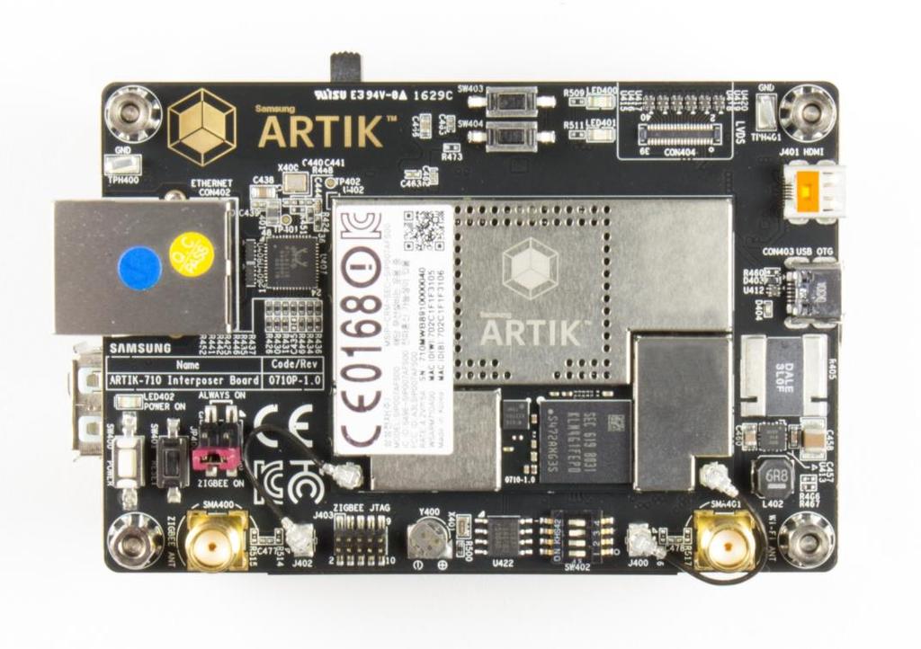
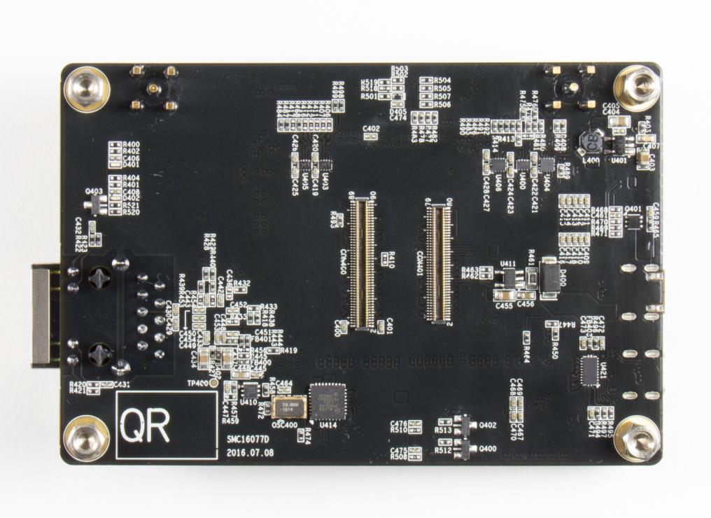


11 The Interposer Board as depicted in Figure 5 highlights the most important components on the Interposer board. 11


12 This section describes the various boot modes that are supported on the ARTIK 710 Development Environment. Table 2 and Figure 6 show how to manipulate SW4 and where SW4 is located on the Interposer Board to set the various booting options that are available on the ARTIK 710 Development Environment. SW4 Comment emmc 1st Boot SD Card 1st Boot USB 1st Boot 1 Off Off On 2 Off Off On 3 Hardware Board Revision 0.5 On On X 3 Hardware Board Revision 1.0 Off Off X 4 Off On X 12


13 The Interposer board has 1x USB OTG connector located as can be seen in Figure 7. The Interposer board has 1x HDMI 1.4a connector (Micro D-Type) located as can be seen in Figure 8. The following video formats are supported:


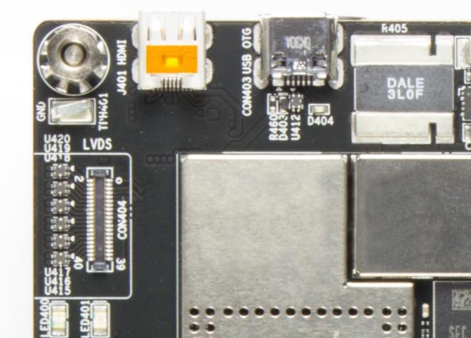


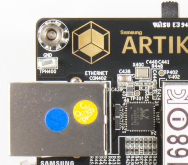

14 The Interposer board has 1x LVDS Interface containing 5x data channels and 1x clock channel, its location can be seen in Figure 9. The available maximum resolution is The Interposer board has 1x Ethernet Interface, its location can be seen in Figure 10. The Ethernet Interface is based on 802.3az-2010 complying to the Energy Efficient Ethernet (EEE) standard. The maximum theoretical speed of the interface is 1000Mbps. 14


15 When using Wi-Fi/Bluetooth (same antenna) or ZigBee the included antenna s need to be attached to the Interposer Board, see also Figure 11. The most important antenna properties are conveyed in Table 3. Antenna Property Antenna peak gain Frequency Connector type Antenna size Dipole Antenna +1.43dB (2.4GHz)/+0.91dB (5GHz) 2.4GHz, 5GHz (for Wi-Fi, BT, ZigBee) SMA-M 108.7mm 15


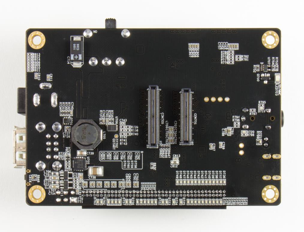


16 The Platform Board as depicted in Figure 12 highlights the most important components on the platform board. 16


![When the jumpers [JP1-JP4] are in the 1-2](/docs-images/72/66415280/images/17-16.jpg "position, (DC-5V Adapter mode or Battery")

![time. When the jumpers [JP1-JP4] are in](/docs-images/72/66415280/images/17-19.jpg "the 2-3 position, (Battery Charging Mode)")


17 Through selection of the Jumpers JP1-JP4 the power source can be selected. When power is provided from a DC-5V Adapter or a Battery, all jumpers are in the 1-2 position. When power is provided from the DC-5V Adapter and at the same time a battery is connected that is being charged (Battery Charging Mode), all jumpers are in the 2-3 position. When the jumpers [JP1-JP4] are in the 1-2 position, (DC-5V Adapter mode or Battery mode) either connect a battery or the DC- 5V adapter but never both at the same time. When the jumpers [JP1-JP4] are in the 2-3 position, (Battery Charging Mode) connect both a battery and the DC-5V Adapter. Figure 13 shows the default settings and how to switch between the settings. When the ARTIK 710 Development Board is used with an external power adapter make certain that you use a 5V-5A adapter with a 2.1x5.5mm plug. Warning : whenever JP1-JP4 are all in 1-2 mode, connect either a Battery or a DC-5V Adapter, but NEVER connect both at the same time! 17


, whereas the")

18 The Platform board has 1x SD-CARD interface supporting SD3.0 located as can be seen in Figure 14. The Platform board has 1x 4 pin ear jack interface supporting stereo audio as can be seen in Figure 15. The Platform board has 1x MIPI DSI and 1x MIPI CSI interface. The location of the DSI Display interface can be seen in Figure 16. The location of the MIPI CSI interface can be seen in Figure 17.The MIPI DSI interface can operate at a maximum resolution of WUXGA (1920x1200), whereas the MIPI CSI interface can have a static resolution of 5M pixels or a dynamic resolution for video capturing of 1080P. 18
19 19


20 The Platform board carries 2x USB 2.0 Interfaces. The location of the USB 2.0 interfaces can be seen in Figure 18. The Platform board has 1x expansion connector that can be seen in Figure 19. This connector enables for expansion possibilities. 20


21 Figure 20 shows the highlights of the connector IF board. In addition Table 4 with J2 and Table 5 with J3 show the pinout of the connectors with its meaning. Pin Name Pin Number Pin Number Pin Name XADC1 1 2 GND XADC2 3 4 ADD_XGPIO0 XADC3 5 6 ADD_XGPIO1 XADC4 7 8 ADD_XGPIO2 XADC ADD_XGPIO3 GND ADD_XGPIO4 ADD_XI2C0_SCL ADD_XGPIO5 ADD_XI2C0_SDA ADD_XGPIO6 GND ADD_XGPIO7 ADD_XSPI0_CS ADD_XGPIO8 ADD_XSPI0_CLK ADD_XGPIO9 ADD_XSPI0_MISO GND ADD_XSPI0_MOSI ADD_XAGPIO0 GND GND NC ADD_XPWM0_OUT MICOM_GPIO GND GND ADD_XUART0_RX NC ADD_XUART0_TX 21


![Description Power Source Default Value Connect DCDC_5V_1 Place Jumper J20:[1-2] I2C, UART, GPIO VDDEXT_33_OFF Place Jumper](/docs-images/72/66415280/images/22-17.jpg "J20:[3-4] VDDEXT_18_OFF Place Jumper J20:[5-6] DC5V Place Jumper J21:[1-2] XAGPIO VDD_EXT3P3_ALIVE Place Jumper J21:[3-4]")
22 Pin Name Pin Number Pin Number Pin Name NC GND GND XADC0 Pin Name Pin Number Pin Number Pin Name GND 1 2 MICOM_GPIO1 GND 3 4 MICOM_GPIO2 GND 5 6 MICOM_GPIO3 GND 7 8 MICOM_GPIO4 DC5V 9 10 MICOM_GPIO MICOM_GPIO6 VBAT_MAIN MICOM_GPIO MICOM_GPIO8 AP_VDDIO MICOM_GPIO MICOM_GPIO10 VDD_EXT1P8_ALIVE MICOM_GPIO MICOM_GPIO12 VDD_EXT1P MICOM_GPIO MICOM_GPIO14 VDD_EXT3P3_ALIVE GND GND VDD_EXT3P GND GND VDD_EXT5P0_ GND GND Through selection of the Jumpers J20 and J21 you can choose the IO power source (I 2 C, UART, GPIO) or the XAGPIO power source of either, 1.8V, 3.3V or 5V. Figure 21 shows how to set the various jumpers to switch between power sources. Description Power Source Default Value Connect DCDC_5V_1 Place Jumper J20:[1-2] I2C, UART, GPIO VDDEXT_33_OFF Place Jumper J20:[3-4] VDDEXT_18_OFF Place Jumper J20:[5-6] DC5V Place Jumper J21:[1-2] XAGPIO VDD_EXT3P3_ALIVE Place Jumper J21:[3-4] VDD_EXT1P8_ALIVE Place Jumper J21:[5-6] 22


23 This section will describe how to start working with your ARTIK 710 Development Environment by setting up a serial connection on your development PC and booting up the ARTIK 710 Development Environment. As a first step we will select a serial console to communicate with the ARTIK 710 Module that is located on the ARTIK 710 Development Environment. You can use a typical Linux serial console as depicted in Figure 22, using the serial connector. If your PC does not have a serial port, use the micro-usb B serial cable instead. To use the serial USB cable you need to install the associated device driver. Figure 23 depicts the USB serial cable and where it is hooked up to the Platform Board. 23


. 3. Check the COM port number on your PC when you connect the USB serial cable.")

24 Setting up a connection with the ARTIK 710 Module can be done in a wired or wireless manner. Here we choose to install PuTTY a free serial console. The software can be downloaded from Once downloaded go through the following steps: 1. Open the device manager on the control panel. 2. When using a PC install the USB to Serial driver. The driver can be found at the following location : ( For other drivers please visit ( 3. Check the COM port number on your PC when you connect the USB serial cable. In our case the COM port allocated is COM3. 4. Set the PuTTY configuration as follows: a. Set the Serial line as the COM port number found in step 3. b. Set the COM speed to "115200". c. Set the connection type to "Serial". d. Save the session under ARTIK-Pro. 5. Select your saved session and click the Open button. 24


25 To power up the ARTIK 710 Development Environment you first have to connect the power adapter and the Platform Board as shown in Figure 24. In addition make certain that the jumpers JP1-JP4 located on the Platform Board are set in state 1-2 see Configuration of External Power Source section for details. 25


26 Turn on the power switch as shown in Figure 25. Once the power switch is turned on, push the power button (SW2), as depicted in Figure 26, for about 1 second. Once released the booting process will start and you should see booting messages from your console, using the serial connection that you previously established. 26
27 INFORMATION IN THIS DOCUMENT IS PROVIDED IN CONNECTION WITH THE SAMSUNG ARTIK DEVELOPMENT BOARD AND ALL RELATED PRODUCTS, UPDATES, AND DOCUMENTATION (HEREINAFTER SAMSUNG PRODUCTS ). NO LICENSE, EXPRESS OR IMPLIED, BY ESTOPPEL OR OTHERWISE, TO ANY INTELLECTUAL PROPERTY RIGHTS IS GRANTED BY THIS DOCUMENT. THE LICENSE AND OTHER TERMS AND CONDITIONS RELATED TO YOUR USE OF THE SAMSUNG PRODUCTS ARE GOVERNED EXCLUSIVELY BY THE SAMSUNG ARTIK DEVELOPER LICENSE AGREEMENT THAT YOU AGREED TO WHEN YOU REGISTERED AS A DEVELOPER TO RECEIVE THE SAMSUNG PRODUCTS. EXCEPT AS PROVIDED IN THE SAMSUNG ARTIK DEVELOPER LICENSE AGREEMENT, SAMSUNG ELECTRONICS CO., LTD. AND ITS AFFILIATES (COLLECTIVELY, SAMSUNG ) ASSUMES NO LIABILITY WHATSOEVER, INCLUDING WITHOUT LIMITATION CONSEQUENTIAL OR INCIDENTAL DAMAGES, AND SAMSUNG DISCLAIMS ANY EXPRESS OR IMPLIED WARRANTY, ARISING OUT OF OR RELATED TO YOUR SALE, APPLICATION AND/OR USE OF SAMSUNG PRODUCTS INCLUDING LIABILITY OR WARRANTIES RELATED TO FITNESS FOR A PARTICULAR PURPOSE, MERCHANTABILITY, OR INFRINGEMENT OF ANY PATENT, COPYRIGHT, OR OTHER INTELLECTUAL PROPERTY RIGHT. SAMSUNG RESERVES THE RIGHT TO CHANGE PRODUCTS, INFORMATION, DOCUMENTATION AND SPECIFICATIONS WITHOUT NOTICE. THIS INCLUDES MAKING CHANGES TO THIS DOCUMENTATION AT ANY TIME WITHOUT PRIOR NOTICE. THIS DOCUMENTATION IS PROVIDED FOR REFERENCE PURPOSES ONLY, AND ALL INFORMATION DISCUSSED HEREIN IS PROVIDED ON AN AS IS BASIS, WITHOUT WARRANTIES OF ANY KIND. SAMSUNG ASSUMES NO RESPONSIBILITY FOR POSSIBLE ERRORS OR OMISSIONS, OR FOR ANY CONSEQUENCES FROM THE USE OF THE DOCUMENTATION CONTAINED HEREIN. Samsung Products are not intended for use in medical, life support, critical care, safety equipment, or similar applications where product failure could result in loss of life or personal or physical harm, or any military or defense application, or any governmental procurement to which special terms or provisions may apply. This document and all information discussed herein remain the sole and exclusive property of Samsung. All brand names, trademarks and registered trademarks belong to their respective owners. For updates or additional information about Samsung ARTIK, contact the Samsung ARTIK team via the Samsung ARTIK website at Copyright 2016 Samsung Electronics Co., Ltd. All rights reserved. No part of this publication may be reproduced, stored in a retrieval system, or transmitted in any form or by any means, electric or mechanical, by photocopying, recording, or otherwise, without the prior written consent of Samsung Electronics. 27
 ... 2... 3... 4... 5... 6... 6... 6... 7... 8... 8... 8... 9... 9... 10... 10... 10... 11... 11... 12... 13... 13... 14... 14... 15... 16... 17... 18... 19... 20... 21 ... 6... 7... 8... 8... 9... 9...
SAMSUNG ELECTRONICS RESERVES THE RIGHT TO CHANGE PRODUCTS, INFORMATION AND SPECIFICATIONS WITHOUT NOTICE. Products and specifications discussed
 SAMSUNG ELECTRONICS RESERVES THE RIGHT TO CHANGE PRODUCTS, INFORMATION AND SPECIFICATIONS WITHOUT NOTICE. Products and specifications discussed herein are for reference purposes only. All information discussed
Samsung Memory Card/UFD Authentication Utility
 Samsung Memory Card/UFD Authentication Utility User s Manual. Revision 1.0 LEGAL DISCLAIMER SAMSUNG ELECTRONICS RESERVES THE RIGHT TO CHANGE PRODUCTS, INFORMATION AND SPECIFICATIONS WITHOUT NOTICE. Products
The Information contained herein is subject to change without notice. Revisions may be issued regarding changes and/or additions.
 Cobalt MC Gumstix, Inc. shall have no liability of any kind, express or implied, arising out of the use of the Information in this document, including direct, indirect, special or consequential damages.
Hugo Cunha. Senior Firmware Developer Globaltronics
 Hugo Cunha Senior Firmware Developer Globaltronics NB-IoT Product Acceleration Platforms 2018 Speaker Hugo Cunha Project Developper Agenda About us NB IoT Platforms The WIIPIIDO The Gateway FE 1 About
SABRE Board for Smart Devices
 Quick Start Guide SABRE Board for Smart Devices Based on the i.mx 7Dual Applications Processor SMART APPLICATION BLUEPRINT FOR RAPID ENGINEERING (SABRE) Quick Start Guide GET TO KNOW SABRE BOARD FOR SMART
PremierWave 2050 Enterprise Wi-Fi IoT Module Evaluation Kit User Guide
 PremierWave 2050 Enterprise Wi-Fi IoT Module Evaluation Kit User Guide Part Number 900-765-R Revision A February 2016 Intellectual Property 2016 Lantronix, Inc. All rights reserved. No part of the contents
EX-9686U/A-L(A9) Hardware User Manual
 Hardware User Manual") EX-9686U/A-L(A9) Hardware User Manual Release Notes Version Release Date Notes 1.00 November, 2013 Initial Release 2.00 January, 2014 The 2 nd release Disclaimer This documentation is provided for use
EX-9686U/A-L(A9) Hardware User Manual Release Notes Version Release Date Notes 1.00 November, 2013 Initial Release 2.00 January, 2014 The 2 nd release Disclaimer This documentation is provided for use
NXP-Freescale i.mx6 MicroSoM i2. Dual Core SoM (System-On-Module) Rev 1.3
 Rev 1.3") NXP-Freescale i.mx6 MicroSoM i2 Dual Core SoM (System-On-Module) Rev 1.3 Simple. Robust. Computing Solutions SolidRun Ltd. 3 Dolev st., 3rd floor, P.O. Box 75 Migdal Tefen 2495900, Israel. www.solid-run.com
NXP-Freescale i.mx6 MicroSoM i2 Dual Core SoM (System-On-Module) Rev 1.3 Simple. Robust. Computing Solutions SolidRun Ltd. 3 Dolev st., 3rd floor, P.O. Box 75 Migdal Tefen 2495900, Israel. www.solid-run.com
NXP-Freescale i.mx6 MicroSoM i4pro. Quad Core SoM (System-On-Module) Rev 1.3
 Rev 1.3") NXP-Freescale i.mx6 MicroSoM i4pro Quad Core SoM (System-On-Module) Rev 1.3 Simple. Robust. Computing Solutions SolidRun Ltd. 3 Dolev st., 3rd floor, P.O. Box 75 Migdal Tefen 2495900, Israel. www.solid-run.com
NXP-Freescale i.mx6 MicroSoM i4pro Quad Core SoM (System-On-Module) Rev 1.3 Simple. Robust. Computing Solutions SolidRun Ltd. 3 Dolev st., 3rd floor, P.O. Box 75 Migdal Tefen 2495900, Israel. www.solid-run.com
SOM i1 Single Core SOM (System-On-Module) Rev 1.5
 Rev 1.5") NXP-Freescale i.mx6 SOM i1 Single Core SOM (System-On-Module) Rev 1.5 Simple. Robust. Computing Solutions SolidRun Ltd. 7 Hamada st., Yokne am Illit, 2495900, Israel www.solid-run.com 1 Page Document revision
NXP-Freescale i.mx6 SOM i1 Single Core SOM (System-On-Module) Rev 1.5 Simple. Robust. Computing Solutions SolidRun Ltd. 7 Hamada st., Yokne am Illit, 2495900, Israel www.solid-run.com 1 Page Document revision
NXP-Freescale i.mx6. Dual Core SOM (System-On-Module) Rev 1.5
 Rev 1.5") NXP-Freescale i.mx6 SOM i2ex Dual Core SOM (System-On-Module) Rev 1.5 Simple. Robust. Computing Solutions SolidRun Ltd. 7 Hamada st., Yokne am Illit, 2495900, Israel www.solid-run.com 1 Page Document revision
NXP-Freescale i.mx6 SOM i2ex Dual Core SOM (System-On-Module) Rev 1.5 Simple. Robust. Computing Solutions SolidRun Ltd. 7 Hamada st., Yokne am Illit, 2495900, Israel www.solid-run.com 1 Page Document revision
Creator Ci40 product brief
 Creator Ci40 is a high-performance, low-power IoT hub that packs Ethernet, Wi-Fi, 802.11b/g/n/ac, Bluetooth Classic and Low Energy and an 802.15.4 radio onto a powerful IoT gateway with expansion ports
. SMARC 2.0 Compliant
 MSC SM2S-IMX8 NXP i.mx8 ARM Cortex -A72/A53 Description The new MSC SM2S-IMX8 module offers a quantum leap in terms of computing and graphics performance. It integrates the currently most powerful i.mx8
IOT-GATE-iMX7 Datasheet
 IOT-GATE-iMX7 Datasheet Industrial Internet of Things Gateway Product Specification v.1.3 Capable, compact, affordable: i.mx7 Dual IoT-Gate has been designed to answer demanding IoT application requirements
IOT-GATE-RPI. Reference Guide
 IOT-GATE-RPI Reference Guide 2018 CompuLab No warranty of accuracy is given concerning the contents of the information contained in this publication. To the extent permitted by law, no liability (including
M M WIFI Module
 M1000 150M WIFI Module Stable and High Performance 32bit MIPS Processor Compliant with IEEE 802.11n standard, up to 150Mbps Data Rate Small and Castellated Mounting Holes Design 3.3VDC Input Power, Low
IOT x86 Joule Gateway
 IOT x86 Joule Gateway TM Gumstix, Inc. shall have no liability of any kind, express or implied, arising out of the use of the Information in this document, including direct, indirect, special or consequential
LPC1788 Mio Board. User Manual. Revision 1.0 1
 User Manual http://coineltech.com Revision 1.0 1 Designed by CoiNel Technology Solutions LLP No-32, 2 nd Floor, HAPBCO Tower, 9 th Main, RPC Layout, Hampinagar, Bangalore-560040 State: Karnataka Country:
The Information contained herein is subject to change without notice. Revisions may be issued regarding changes and/or additions.
 Garret 50C TM Gumstix, Inc. shall have no liability of any kind, express or implied, arising out of the use of the Information in this document, including direct, indirect, special or consequential damages.
SOM IB8000 Quad Core SOM (System-On-Module) Rev 1.3
 Rev 1.3") Intel Braswell SOM IB8000 Quad Core SOM (System-On-Module) Rev 1.3 Simple. Robust. Computing Solutions SolidRun Ltd. 7 Hamada st., Yokne am Illit, 2495900, Israel www.solid-run.com 1 Page Document revision
Intel Braswell SOM IB8000 Quad Core SOM (System-On-Module) Rev 1.3 Simple. Robust. Computing Solutions SolidRun Ltd. 7 Hamada st., Yokne am Illit, 2495900, Israel www.solid-run.com 1 Page Document revision
Samsung USB Flash Drive : DUO Plus Lineup
 Samsung USB Flash Drive : DUO Plus Lineup 2018 Data Sheet 1 DISCLAIMER SAMSUNG ELECTRONICS RESERVES THE RIGHT TO CHANGE PRODUCTS, INFORMATION AND SPECIFICATIONS WITHOUT NOTICE. Products and specifications
Quick Start Guide Multisensory Enablement Kit i.mx 8QuadXPlus MEK CPU Board. Based on i.mx 8QuadXPlus Applications Processor
 Quick Start Guide Multisensory Enablement Kit i.mx 8QuadXPlus MEK CPU Board Based on i.mx 8QuadXPlus Applications Processor Quick Start Guide GET TO KNOW THE MEK BASED ON i.mx 8QUADXPLUS APPLICATIONS PROCESSOR
M M WIFI Module
 M1002 300M WIFI Module Stable and High Performance 32bit MIPS Processor Compliant with IEEE 802.11n standard, up to 300Mbps Data Rate Small and Pin Hole Mounting Design 3.3VDC Input Power, Low Power Consumption
. Micro SD Card Socket. SMARC 2.0 Compliant
 MSC SM2S-IMX6 NXP i.mx6 ARM Cortex -A9 Description The design of the MSC SM2S-IMX6 module is based on NXP s i.mx 6 processors offering quad-, dual- and single-core ARM Cortex -A9 compute performance at
RK3036 Kylin Board Hardware Manual V0.1
 RK3036 Kylin Board Hardware Manual V0.1 Content 1 Introduction 1.1 Kylin at first glance 1.2 Boot to console 1.3 Key features 1.4 Block diagram 2 Key parts in details 2.1 Processor 2.2 Memory 2.3 Storage
CM10 Rugged COM Express with TI Sitara ARM Cortex-A15
 CM10 Rugged COM Express with TI Sitara ARM Cortex-A15 Computer-On-Module www.men.de/products/cm10/» TI Sitara ARM Cortex-A15 AM57xx» Single or dual core processor» Built-in quad core PRU and DSP core»
CHANGING THE MODES OF MOD-WIFI-ESP8266-DEV
 CHANGING THE MODES OF MOD-WIFI-ESP8266-DEV REFERENCE Revision B, March 2018 Designed by OLIMEX Ltd, 2014 All boards produced by Olimex LTD are ROHS compliant DISCLAIMER 2018 Olimex Ltd. Olimex, logo and
ARTiGO A600 Linux EVK v1.2.1
 IMAGE INSTALLATION GUIDE ARTiGO A600 Linux EVK v1.2.1 1.00-06232016-173700 Copyright Copyright 2016 VIA Technologies Incorporated. All rights reserved. No part of this document may be reproduced, transmitted,
KITRA 710C board data sheet KITRA 710C. Data sheet 29/10/2018
 KITRA 710C Data sheet 29/10/2018 Summary.1 REVISION HISTORY 2.2 KITRA 710C IMAGES 3.3 INTRODUCTION 4.4 DESCRIPTION 4.5 HARDWARE & COMPONENTS DETAIL 4.5.1 Samsung ARTIK 710 module 4.5.2 Accelerometers -
Raspberry Pi Compute Development board
 Raspberry Pi Compute Development board TM Gumstix, Inc. shall have no liability of any kind, express or implied, arising out of the use of the Information in this document, including direct, indirect,
The TechNexion Difference
 The TechNexion Difference Faster time-to-market through Open Design System on Modules are designed to speed up and reduce the cost of development for embedded devices. But these benefits are only possible,
LPC2148 DEV BOARD. User Manual.
 LPC2148 DEV BOARD User Manual www.coineltech.com www.coineltech.com Designed by CoiNel Technology Solutions LLP No-816, 2 nd Floor, 4 th B Cross, 9 th A Main, RPC Layout, Vijaynagar, Bangalore-560040 State:
SABRE for Automotive Infotainment Quick Start Guide. Smart Application Blueprint for Rapid Engineering Based on the i.mx 6 Series
 SABRE for Automotive Infotainment Quick Start Guide Smart Application Blueprint for Rapid Engineering Based on the i.mx 6 Series About SABRE Platform for Automotive Infotainment Based on the the i.mx 6
VAR-EXT-CB8 Datasheet Camera Extension Board for VAR-DT8MCustomBoard & SPEAR-MX8CustomBoard V 1.x
 Rev. 1.00, 07/2018 VAR- EXT- CB8 VARISCITE LTD. VAR-EXT-CB8 Datasheet Camera Extension Board for VAR-DT8MCustomBoard & SPEAR-MX8CustomBoard V 1.x VARISCITE LTD. VAR-EXT-CB8 Datasheet 2018 All Rights Reserved.
Quick Start Guide. SABRE Platform for Smart Devices Based on the i.mx 6 Series
 Quick Start Guide SABRE Platform for Smart Devices Based on the i.mx 6 Series Quick Start Guide About the SABRE Platform for Smart Devices Based on the i.mx 6 Series The Smart Application Blueprint for
DATASHEET. MK-070C-HP High Performance 7 Inch Capacitive Touch Display. Amulet. Technologies. July 2015 Revision A
 High Performance 7 Inch Capacitive Touch Display DATASHEET July 2015 Revision A Introduction The MK-070C is the newest family member in the Display Module product line. The new 7 Capacitive Display Module
TechNexion PICO SOM Expansion Board
 TechNexion PICO SOM Expansion Board TM Gumstix, Inc. shall have no liability of any kind, express or implied, arising out of the use of the Information in this document, including direct, indirect, special
Gumstix Pi Compute USB-Ethernet
 Gumstix Pi Compute USB-Ethernet TM Gumstix, Inc. shall have no liability of any kind, express or implied, arising out of the use of the Information in this document, including direct, indirect, special
QUICK START GUIDE VAB-630. Android EVK v
 QUICK START GUIDE VAB-630 Android EVK v1.0.3 1.00-08112017-110800 Copyright Copyright 2017 VIA Technologies Incorporated. All rights reserved. No part of this document may be reproduced, transmitted, transcribed,
The Information contained herein is subject to change without notice. Revisions may be issued regarding changes and/or additions.
 Pepper 43R TM Gumstix, Inc. shall have no liability of any kind, express or implied, arising out of the use of the Information in this document, including direct, indirect, special or consequential damages.
UM User Manual for LPC54018 IoT Module. Rev November Document information
 UM11078 for Rev. 1.01 27 November 2017 Document information Info Content Keywords LPC54018, OM40007, GT1216, UM11078 Abstract Revision history Rev Date Description 1.0 20171122 First draft 1.01 20171127
i.mx 8M MINI System-On-Module (SOM) Hardware Architecture
 Hardware Architecture") i.mx 8M MINI System-On-Module (SOM) Hardware Architecture Document No: IMX8M-MINI-SOM-HA Version: 1.0 Date: February 26, 2019 Table of Contents 1. INTRODUCTION... 3 2. HARDWARE PLATFORM... 3 2.1. HARDWARE
i.mx 8M MINI System-On-Module (SOM) Hardware Architecture Document No: IMX8M-MINI-SOM-HA Version: 1.0 Date: February 26, 2019 Table of Contents 1. INTRODUCTION... 3 2. HARDWARE PLATFORM... 3 2.1. HARDWARE
Hardware Manual Bubblegum96. Version:
 Hardware Manual Bubblegum96 Version:1.1 2016-5-18 Disclaimer Circuit diagrams and other information relating to products of Actions Semiconductor Company, Ltd. ( Actions ) are included as a means of illustrating
User Manual. for the. KT-PCIe-DVI KT-PCIe-DVI
 KTD-00766-A Public User Manual Date: 2009-03-19 Page 1 of 11 User Manual for the 820957 KT-PCIe--HDMI 820959 KT-PCIe- Designed primarily for KT690 and KT780 motherboards 820957 KT-PCIe--HDMI 820959 KT-PCIe-
No: SW1.12_4.0.2 V F
 Jupiter-F 2 User s Manual 2010 Navman Wireless OEM. All Rights Reserved. SiRF and SiRF logo are registered trademarks of SiRF Technology, Inc. SiRFstar, SiRFLoc, Push-to-Fix, and Trickle-Power are trademarks
USER GUIDE. ATWINC1500 Xplained Pro. Preface
 USER GUIDE ATWINC1500 Xplained Pro Preface Atmel ATWINC1500 Xplained Pro is an extension board to the Atmel Xplained Pro evaluation platform. The extension board allows to evaluate the Atmel ATWINC1510/1500
II. PROPOSED SYSTEM AND IMPLEMENTATION
 Automatic Gate Security System by using Raspberry Pi with Image Processing Mr. Mogare Sumit R. 1, Sanagare Prathamesh S. 2, Ms. Anjarlekar Shraddha S. 3, Mr. Kharat Ratnadipak N. 4, Mr. Shikalgar Isaq
The Information contained herein is subject to change without notice. Revisions may be issued regarding changes and/or additions.
 Poblano 43C TM Gumstix, Inc. shall have no liability of any kind, express or implied, arising out of the use of the Information in this document, including direct, indirect, special or consequential damages.
xpico 200 Series Evaluation Kit User Guide
 xpico 200 Series Evaluation Kit User Guide This guide describes how to setup the xpico 200 series evaluation kit and provides the information needed to evaluate the included xpico 240 or xpico 250 embedded
Overview of the Raspberry Pi Models 3B & 2B
 Overview of the Raspberry Pi Models 3B & 2B (Let's look at the hardware!) Rick Commo, K7LOG Max Vaughan, KF7MAX What's really different between the original 2B and the 3B? Parameter Architecture CPU
User Manual. Nvidia Jetson Series Carrier board Aetina ACE-N622
 User Manual Nvidia Jetson Series Carrier board Aetina ACE-N622 i Document Change History Version Date Description Authors V1 2018/05/23 Initial Release. Eric Chu V2 2018/06/22 Specification change Eric
VK5100-imx6 Development Platform Quick Start Guide
 VK5100-imx6 Development Platform Quick Start Guide VEST-VK5100-QSG-001 Copyright 2016 Advanced Products Corporation Pte Ltd. All rights reserved. No part of this document may be photocopied, reproduced,
USB-C DOCK USER GUIDE
 USB-C DOCK USER GUIDE CONTENTS INTRODUCTION...1 1.1 Minimum System Requirements 1.2 Package Contents 1.3 About This Manual 1.4 Front View 1.5 Rear View SUPPORT RESOURCES...4 2.1 Connection 2.2 Usage Notes
COM-RZN1D - Hardware Manual
 COM-RZN1D - Hardware Manual Hardware Manual 4 / 01.10.2018 emtrion GmbH Copyright 2018 emtrion GmbH All rights reserved. This documentation may not be photocopied or recorded on any electronic media without
Datasheet BT85x Series Development Kits
 A BT85x Series Development Kits Applicable to the following Laird part numbers: DVK-BT850-SA DVK-BT850-ST Version 1.0 REVISION HISTORY Version Date Notes Contributor Approver 1.0 12 Jan 2018 Initial Release
Dust Networks. SmartMesh LTP5903PC Integration Guide
 Dust Networks SmartMesh LTP5903PC Integration Guide Contents Related Documents...3 Conventions and Terminology...3 Revision History...3 1 Introduction...4 Product Overview...4 2 Application Circuits...5
Ethernet1 Xplained Pro
 Ethernet1 Xplained Pro Part Number: ATETHERNET1-XPRO The Atmel Ethernet1 Xplained Pro is an extension board to the Atmel Xplained Pro evaluation platform. The board enables the user to experiment with
Toradex Colibri Development Board
 Toradex Colibri Development Board TM Gumstix, Inc. shall have no liability of any kind, express or implied, arising out of the use of the Information in this document, including direct, indirect, special
ET-UARTSWD Users Guide
 User s Guide ET-UARTSWD Users Guide Power Application Controller s www.active-semi.com Copyright 2018 Active-Semi, Inc. CONTENTS Contents...2 Overview...3 1. ET-UARTSWD Resources...6 1.1 Provided Connectors...6
NXP-Freescale i.mx6 MicroSoM i2. Dual Core SoM (System-On-Module)
") NXPFreescale i.mx6 MicroSoM i2 Dual Core SoM (SystemOnModule) Simple. Robust. Computing Solutions SolidRun Ltd. 3 Dolev st., 3rd floor, P.O. Box 75 Migdal Tefen 2495900, Israel. www.solidrun.com Overview
NXPFreescale i.mx6 MicroSoM i2 Dual Core SoM (SystemOnModule) Simple. Robust. Computing Solutions SolidRun Ltd. 3 Dolev st., 3rd floor, P.O. Box 75 Migdal Tefen 2495900, Israel. www.solidrun.com Overview
VENUS_ Driving Board and 39.6 Prism Display
 VENUS_ Driving Board and 39.6 Prism Display Table of Contents 1 Hardware Requirements... 1 (1) PACKAGE CONTENTS... 1 (2) VENUS Specification... 2 (3) Prism product Specification... 3 2 Hardware Guide...
DC connector: 5VDC, 2,5A, round; 2,1x5,5x10 mm, inside positive External power supply: AC 230V 50/60Hz, 5V 2,5A out
 Smarthub CUBE-1V0-EU Z-Wave and EnOcean based home automation central gateway. Connected to your home network and running the Futurehome software stack, it provides communication between supported smart
SKY LF: 2.4 to 2.5 GHz SP3T Switch
 DATA SHEET SKY13586-678LF: 2.4 to 2.5 GHz SP3T Switch Applications 802.11 a/b/g/n/ac WLAN networks Bluetooth systems Smartphones Connectivity modules RF1 RF2 RFC Features Positive low voltage control:
USB-C DOCK USER GUIDE
 USB-C DOCK USER GUIDE CONTENTS Introduction...1 1.1 Minimum System Requirements 1.2 Package Contents 1.3 About This Manual 1.4 Front View 1.5 Rear View Support Resources...4 2.1 Connection 2.2 Usage Notes
Quick Start Guide. i.mx 6SoloLite Evaluation Kit
 Quick Start Guide i.mx 6SoloLite Evaluation Kit Quick Start Guide About the i.mx 6SoloLite Evaluation Kit The i.mx 6SoloLite evaluation kit (EVK) offers a solid platform to evaluate the i.mx 6 series single-core
PAC5523EVK1. Power Application Controllers. PAC5523EVK1 User s Guide. Copyright 2017 Active-Semi, Inc.
 PAC5523EVK1 Power Application Controllers PAC5523EVK1 User s Guide www.active-semi.com Copyright 2017 Active-Semi, Inc. CONTENTS Contents...2 Overview...3 PAC5523EVK1 Resources...5 Pinout and Signal Connectivity...5
SABRE Platform for Auto Infotainment
 Quick Start Guide SABRE Platform for Auto Infotainment Based on the i.mx 6QuadPlus Applications Processor SMART APPLICATION BLUEPRINT FOR RAPID ENGINEERING (SABRE) i.mx 6DualPlus can be emulated on i.mx
[Type here] M907. Bluetooth 4.2 Low Energy/Zigbee/RF4CE/Thread SiP Module with MCU and integrated antenna
![[Type here] M907. Bluetooth 4.2 Low Energy/Zigbee/RF4CE/Thread SiP Module with MCU and integrated antenna](/thumbs/87/96540692.jpg "[Type here] M907. Bluetooth 4.2 Low Energy/Zigbee/RF4CE/Thread SiP Module with MCU and integrated antenna") [Type here] M907 Bluetooth 4.2 Low Energy/Zigbee/RF4CE/Thread SiP Module with MCU and integrated antenna Preliminary DATASHEET 19 th April, 2018 Table of Contents 1 Product Brief... 1 2 Features and Applications...
[Type here] M907 Bluetooth 4.2 Low Energy/Zigbee/RF4CE/Thread SiP Module with MCU and integrated antenna Preliminary DATASHEET 19 th April, 2018 Table of Contents 1 Product Brief... 1 2 Features and Applications...
USER MANUAL FOR MF0200 GATEWAY BOX VERSION 2.0
 USER MANUAL FOR MF0200 GATEWAY BOX VERSION 2.0 COPYRIGHT & TRADEMARKS 2016 Mentor Graphics Corporation, all rights reserved. This document contains information that is proprietary to Mentor Graphics Corporation
OnRISC. OnRISC Baltos ir 2110
 OnRISC OnRISC Baltos ir 2110 Hardware Manual Edition: October 2015 Tel: +49 40 528 401 0 Fax: +49 40 528 401 99 Web: www.visionsystems.de Support: service@visionsystems.de The software described in this
UM LPC General Purpose Shield (OM13082) Rev November Document information. Keywords
 Rev November Document information. Keywords") Rev. 1.0 17 November 2015 User manual Document information Info Content Keywords LPCXpresso, LPC General Purpose Shield, OM13082 Abstract LPC General Purpose Shield User Manual Revision history Rev Date
Rev. 1.0 17 November 2015 User manual Document information Info Content Keywords LPCXpresso, LPC General Purpose Shield, OM13082 Abstract LPC General Purpose Shield User Manual Revision history Rev Date
SAMSUNG ELECTRONICS RESERVES THE RIGHT TO CHANGE PRODUCTS, INFORMATION AND SPECIFICATIONS WITHOUT NOTICE. Products and specifications discussed
 SAMSUNG ELECTRONICS RESERVES THE RIGHT TO CHANGE PRODUCTS, INFORMATION AND SPECIFICATIONS WITHOUT NOTICE. Products and specifications discussed herein are for reference purposes only. All information discussed
NEBULA User manual. 15.6, 21.5 Kiosk Tablet
 NEBULA User manual 15.6, 21.5 Kiosk Tablet Thank you for purchasing a Glory Star Group Limited product. We recommend reading this user guide carefully in order to achieve the optimal performance and to
CMSIS DAP Setup. Document Version History Document Version ngxtechnologies.com 2
 Document Version History Document Version - 1.0 Author Vinayak ngxtechnologies.com 2 Table of Contents INTRODUCTION...4 REQUIREMENTS...4 HARDWARE...4 SOFTWARE...4 SETUP...4 DISCLAIMERS...8 ngxtechnologies.com
VK8300-imx6 Development Platform Quick Start Guide
 VK8300-imx6 Development Platform Quick Start Guide VEST-VK8300-QSG-001 www.apc-vest.com Copyright 2016 Advanced Products Corporation Pte Ltd. All rights reserved. No part of this document may be photocopied,
pcduino V3B XC4350 User Manual
 pcduino V3B XC4350 User Manual 1 User Manual Contents Board Overview...2 System Features...3 Single-Board Computer Configuration......3 Pin Assignments...4 Single-Board Computer Setup...6 Required Hardware...6
Bluetooth USB Adapter TALUS. User Guide
 Bluetooth USB Adapter TALUS User Guide Revision 0.1 1 User Guide for the TALUS Revision 1.0.1 Firmware version 1.0.X Printed in Korea Copyright Copyright 2008, SystemBase Co., Ltd. All rights reserved.
MIRAGE Sierra mangoh TM IoT WiFi + Bluetooth + NFC Datasheet
 FEATURES WiFi 802.11 a/b/g/n 20 and 40MHz SISO Bluetooth Classic 2.1 Bluetooth Smart 4.1 NFC Forum type 2 Tag NFC Field Detect Wakeup Digital PCM Audio + SBC and A2DP Integrated high performance trace
RE866 Interface User Guide
 RE866 Interface User Guide 1VV0301387 Rev.0 6/16/2017 [04.2016] Mod. 0809 2016-08 Rev.7 SPECIFICATIONS ARE SUBJECT TO CHANGE WITHOUT NOTICE NOTICE While reasonable efforts have been made to assure the
Intel Aero Compute Board
 Intel Aero Compute Board Hardware Features and Usage Rev 1.5.2 INFORMATION IN THIS DOCUMENT IS PROVIDED IN CONNECTION WITH INTEL PRODUCTS. NO LICENSE, EXPRESS OR IMPLIED, BY ESTOPPEL OR OTHERWISE, TO ANY
Raspberry Pi shield board
 Raspberry Pi shield board Table of Contents Hardware Guide 1 1 Hardware Requirements 1 (1) PACKAGE CONTENTS 1 (2) Feature 1 2 Hardware Guide 2 (1) HARDWARE REQUIREMENTS 2 (2) HARDWARE CONNECTION 3 (3)
SBC3100 (Cortex-A72) Single Board Computer
 Single Board Computer") (Cortex-A72) Single Board Computer Ultra High Performance SBC with RK3399 (Cortex-A72 x2 + Cortex-A53 x4) @ 2Ghz : Single Board Computer H310: Input (receiver) Module : Output (display) Module D120: 4xCOM
(Cortex-A72) Single Board Computer Ultra High Performance SBC with RK3399 (Cortex-A72 x2 + Cortex-A53 x4) @ 2Ghz : Single Board Computer H310: Input (receiver) Module : Output (display) Module D120: 4xCOM
[Type here] M904S. Bluetooth 4.0 SiP Module - BT 4.0 LE
![[Type here] M904S. Bluetooth 4.0 SiP Module - BT 4.0 LE](/thumbs/78/78761520.jpg "[Type here] M904S. Bluetooth 4.0 SiP Module - BT 4.0 LE") [Type here] M904S Bluetooth 4.0 SiP Module - BT 4.0 LE Preliminary DATASHEET 26 th March, 2018 Table of Contents 1 Product Brief... 1 2 Features and Applications... 2 3 Block Diagram... 3 4 Technical Specifications...
[Type here] M904S Bluetooth 4.0 SiP Module - BT 4.0 LE Preliminary DATASHEET 26 th March, 2018 Table of Contents 1 Product Brief... 1 2 Features and Applications... 2 3 Block Diagram... 3 4 Technical Specifications...
OK335xS Users Manual Part I - Introduction
 OK335xS Users Manual Part I - Introduction Copyright@2013-2014 http://www.arm9board.net COPYRIGHT STATEMENT Contents (content being images, text, programs and scripts) of this manual is copyright Witech
MIMXRT1020 EVK Board Hardware User s Guide
 NXP Semiconductors Document Number: MIMXRT1020EVKHUG User's Guide Rev. 0, 05/2018 MIMXRT1020 EVK Board Hardware User s Guide 1. Introduction This Hardware User s Guide for the MIMXRT1020 Evaluation Kit
TLK10081 EVM Quick Start Guide Texas Instruments Communications Interface Products
 TLK10081 EVM Quick Start Guide Texas Instruments Communications Interface Products 1 Board Overview +5 V Adapter Input Connector for voltage monitor board Connector for SMA break-out or FPGA board. Allows
USB-C DOCK USER GUIDE
 USB-C DOCK USER GUIDE CONTENTS INTRODUCTION...1 1.1 Minimum System Requirements 1.2 Package Contents 1.3 About This Manual 1.4 Front View 1.5 Rear View SUPPORT RESOURCES...4 2.1 Connection 2.2 Usage Notes
TEOS Hardware System TEOS 8416 / TEOS 1016/ TEOS1216
 TEOS Hardware System TEOS 8416 / TEOS 1016/ TEOS1216 Revision v1.1 November 2011 Copyright 2009~2011 All Rights Reserved Manual Version 1.1 The information contained in this document is subject to change
Document status: Preliminary
 LPC1788-32 OEM Board Feature Highlights The LPC1788-32 OEM Board provides a quick and easy solution for implementing a high-performance ARM Cortex-M3 based design around the LPC1788 from NXP. Build around
Evaluation Board for CS3308. Description CS Channel. Digitally Controlled Analog Volume Control. PC or External Serial Control Input
 Evaluation Board for CS3308 Features Description Single-ended Analog Inputs Single-ended Analog Outputs Supports AC and DC-Coupled Analog I/O Flexible Serial Control I/O Headers Serial Control Input Header
ATZB-SAMR21-XPRO. Preface. SmartConnect USER GUIDE
 SmartConnect ATZB-SAMR21-XPRO USER GUIDE Preface This user guide facilitates how to get started with the Atmel ATZB-SAMR21- XPRO extension board. ATZB-SAMR21-XPRO is targeted for evaluating the features
ZWIR4532 Evaluation Kit User Manual. Description. Features. Kit Contents
 Description The ZWIR4532 Development Kit is a set of three circuit boards intended as an evaluation and application development platform for the ZWIR4532 6LoWPAN module. Each Development Board provides
Get Started SUPPORT WARRANTY. Visit the i.mx community at
 SUPPORT Visit the i.mx community at www.imxcommunity.org. WARRANTY Visit www.nxp.com/warranty for complete warranty information. Get Started Download installation software and documentation under Getting
i.mx 8M EVK Board Hardware User's Guide
 NXP Semiconductors Document Number: IMX8MDQLQEVKHUG User's Guide Rev. 0, 01/2018 i.mx 8M EVK Board Hardware User's Guide 1. Introduction This document is the hardware User s Guide for the i.mx 8M Evaluation
CIKA DEVKIT35P Quick Start Guide
 CIKA DEVKIT35P Quick Start Guide Pag. 1 of 12 CIKA DEVKIT35P Quick Start Guide Rev.1.0 All Rights Reserved. No part of this document may be photocopied, reproduced, stored in a retrieval system, or transmitted,
IGLOO AND SNOWBALL. Philippe Garnier Ecosystem program
 IGLOO AND SNOWBALL Philippe Garnier Ecosystem program DISCLAIMER Copyright ST-Ericsson 2011. All rights reserved. The contents of this document are subject to change without prior notice. ST-Ericsson makes
OnRISC Alekto 2 Hardware Manual
 OnRISC Alekto 2 Hardware Manual Edition: September 2013 Tel: +49 40 528 401 0 Fax: +49 40 528 401 99 Web: www.visionsystems.de Support: service@visionsystems.de The software described in this manual is
Intel Galileo gen 2 Board
 Intel Galileo gen 2 Board The Arduino Intel Galileo board is a microcontroller board based on the Intel Quark SoC X1000, a 32- bit Intel Pentium -class system on a chip (SoC). It is the first board based
Product Datasheet: DWM1001-DEV DWM1001 Module Development Board. Key Features and Benefits
 Product Datasheet: DWM1001-DEV DWM1001 Module Development Board Plug-and-Play Development Board for evaluating the performance of the Decawave DWM1001 module Easily assemble a fully wireless RTLS system,