A7PRO. Jumper TM PC133/VC MHz FSB AGP Pro/4X
|
|
|
- Veronica Lester
- 6 years ago
- Views:
Transcription

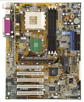
1 A7PRO Jumper TM PC133/VC MHz FSB AGP Pro/4X
2 2000 2
3 3
4 4
5 5
6 6
7 7
8 8
9 9
10 10
11 11
12 / 12


13
14 24.5cm (9.64in) PS/2 JTPWR PWR_FAN VIO USB COM1 Socket ATX Power Connector DIP Switches 3VSBSLT CLRTC CHA_FAN COM2 VID4 VID3 VID2 VID1 F_FAN CPU_FAN DSW DSFID 30.6cm (12in) Row AUX MIC2 CD VIDEO PLED SMB HPHONE MODEM SPK ADN# AUD_EN2 AUD_EN1 WOR A7VPRO WOLCON JEN CHASSIS IR USBPORT IDELED PANEL 14
15 15
16 16
17 A7PRO ON Standby Power OFF Powered Off A7PRO Onboard LED 17
18 A7PRO A7PRO DIP Switches DSW ON OFF ON 1. Frequency Selection 2. Frequency Selection 3. Frequency Selection 4. Frequency Selection OFF ON DSW ON VID4 VID3 VID2 VID JEN A7PRO A7PRO Jumper Mode Setting Jumper Jumper Free Mode (Default) 18
19 Enable Onboard Audio Codec (Default) 1 SPK ADN# AUD_EN2 AUD_EN1 2 Disable Onboard Audio Codec 2 3 SPK ADN# AUD_EN2 AUD_EN1 A7PRO A7PRO Audio Codec Setting 19
20 3VSBSLT Add 3 Volt Add 3 VSB (Default) A7PRO A7PRO PCI 3Volt Selection 20
21 VIO Volt 3.40 Volt 3.56 Volt A7PRO A7PRO VIO Setting 21
22 ON ON ON ON CPU PCI MHz MHz MHz MHz MHz MHz MHz MHz CPU PCI ON MHz MHz ON MHz MHz ON MHz MHz A7PRO CPU PCI ON MHz MHz ON MHz MHz ON MHz MHz ON MHz MHz A7PRO CPU External Frequency Selection ON ON ON ON CPU PCI MHz MHz MHz MHz MHz MHz MHz MHz 22
23 ON ON ON ON 5.0x(5/1) 5.5x(11/2) 6.0x(6/1) 6.5x(13/2) ON ON ON ON 7.0x(7/1) 7.5x(15/2) 8.0x(8/1) 8.5x(17/2) A7PRO ON ON ON ON 9.0x(9/1) 9.5x(119/2) 10.0x(10/1) 10.5x(21/2) A7PRO CPU Core:Bus Frequency Multiple ON 11.0x(11/1) ON 11.5x(23/1) ON 12.0x(12/1) ON 12.5x(25X/1) JumperFree (CPU BUS Freq.) (Freq. Multiple) CPU Freq. Mult. Bus F Athlon 1GHz 10.0x 100MHz [ON] [ON] [ON] [ON] [ON] [ON][OFF][OFF][OFF][ON] Athlon 950MHz 9.5x 100MHz [ON] [ON] [ON] [ON] [ON] [ON][OFF][OFF][ON][OFF] Athlon 900MHz 9.0x 100MHz [ON] [ON] [ON] [ON] [ON] [ON][OFF][OFF][ON][ON] Athlon 850MHz 8.5x 100MHz [ON] [ON] [ON] [ON] [ON] [ON][OFF][ON][OFF][OFF] Athlon 800MHz 8.0x 100MHz [ON] [ON] [ON] [ON] [ON] [ON][OFF][ON][OFF][ON] Athlon 750MHz 7.5x 100MHz [ON] [ON] [ON] [ON] [ON] [ON][OFF][ON][ON][OFF] Athlon 700MHz 7.0x 100MHz [ON] [ON] [ON] [ON] [ON] [ON][OFF][ON][ON][ON] Athlon 650MHz 6.5x 100MHz [ON] [ON] [ON] [ON] [ON] [ON][ON][OFF][OFF][OFF] Athlon 600MHz 6.0x 100MHz [ON] [ON] [ON] [ON] [ON] [ON][ON][OFF][OFF][ON] Duron 750MHz 7.5x 100MHz [ON] [ON] [ON] [ON] [ON] [ON][OFF][ON][ON][OFF] Duron 700MHz 7.0x 100MHz [ON] [ON] [ON] [ON] [ON] [ON][OFF][ON][ON][ON] Duron 650MHz 6.5x 100MHz [ON] [ON] [ON] [ON] [ON] [ON][ON][OFF][OFF][OFF] 23
24 A7PRO A7PRO CPU Core Voltage Selection VID4 VID4 VID3 VID3 VID2 VID2 VID1 VID /1.85Volts 1.775/1.80Volts VID4 VID4 VID3 VID3 VID2 VID2 VID1 VID /1.70Volts 1.625/1.65Volts VID4 VID4 VID3 VID3 VID2 VID2 VID1 VID /1.55Volts 1.475/1.50Volts VID4 VID3 VID2 VID /1.75Volts VID4 VID3 VID2 VID /1.60Volts VID4 VID3 VID2 VID /1.45Volts VID4 VID3 VID2 VID /1.4Volts VID4 VID3 VID2 VID /1.35Volts VID4 VID3 VID2 VID /1.30Volts VID4 VID3 VID2 VID /1.25Volts VID4 VID3 VID2 VID /1.20Volts VID4 VID3 VID2 VID /1.15Volts VID4 VID3 VID2 VID /1.10Volts VID4 VID3 VID2 VID1 CPU Default/ JumperFree (Default) 24
25 25
26 Lock 20 Pins 60 Pins 88 Pins A7PRO A7PRO 168-Pin DIMM Sockets 168-Pin DIMM Notch Key Definitions (3.3V) DRAM Key Position RFU Unbuffered Buffered Voltage Key Position 5.0V Reserved 3.3V 26


27 BLANK AMD Athlon LEVER LOCK A7PRO A7PRO Socket 462 (Socket A) NOTCH 27
28 28 R
29 29
30 30


31 AGP Card without Retention Notch A7PRO 20-pin bay Rib (inside slot) Rib TOP VIEW 28-pin bay A7PRO Accelerated Graphics Port (AGP PRO) 31
32 ASUS MR-I Unlike that of standard cards, the component side of the specially-designed AMR card faces the motherboard s expansion slots when the card is installed A7PRO A7PRO Audio Modem Riser (AMR) Slot 32
33 PS/2 Mouse (6-pin Female) PS/2 Keyboard (6-pin Female) 33
34 USB 0 Universal Serial Bus (USB) 1 COM1 COM2 Serial Ports (9-pin Male) Parallel Port (25-pin Female) 34
35 Game/MIDI (15-pin Female) Line Out Line In Mic 1/8" Stereo Audio Connectors FLOPPY NOTE: Orient the red markings on the floppy ribbon cable to PIN 1. PIN 1 A7PRO A7PRO Floppy Disk Drive Connector 35
36 A7PRO Primary IDE Connector Secondary IDE Connector NOTE: Orient the red markings (usually zigzag) on the IDE ribbon cable to PIN 1. A7PRO IDE Connectors PIN 1 36
37 A7PRO A7PRO Chassis Open Alarm Lead 1 CHASSIS 1 IR Front View Back View +5V IRRX GND IRTX IRTX GND IRRX +5V (NC) A7PRO A7PRO Infrared Module Connector 37
38 IMPORTANT: Requires an ATX power supply with at least 720mA +5 volt standby power WOL_CON +5 Volt Standby PME A7PRO A7PRO Wake-On-LAN Connector Ground WOR Ring# Ground 2 1 A7PRO A7PRO Wake-On-Ring Connector 38
39 PWR_FAN CHA_FAN GND +12V Rotation GND +12V Rotation A7PRO A7PRO 12-Volt Cooling Fan Power F_FAN NC +12V GND CPU_FAN Rotation +12V GND AUX (White) Left Audio Channel Ground Right Audio Channel CD (Black) VIDEO (Green) Left Audio Channel Ground Right Audio Channel A7PRO A7PRO Internal Audio Connectors Modem-In (to Modem) Ground Modem-Out (from Modem) MODEM 39
40 MIC Power MIC Input GND 1 MIC2 A7PRO A7PRO Microphone Header HP OUT LT GND HP OUT RT 1 A7PRO HPHONE A7PRO True-Level Line Out Header 40
41 Bundled 2-port USB Connector Set A7PRO A7PRO USB Ports USB Power USBP2 USBP2+ GND NC USBPORT 6 10 SMBCLK Ground SMBDATA +5V 1 5 USB Power USBP3 USBP3+ GND 1 A7PRO SMB A7PRO SMBus Connector 41
42 +12.0Volts +5V Standby Power Good Ground +5.0 Volts Ground +5.0 Volts Ground +3.3 Volts +3.3 Volts +5.0 Volts +5.0 Volts -5.0 Volts Ground Ground Ground Power Supply On Ground -12.0Volts +3.3Volts A7PRO A7PRO ATX Power Connector ATX JTPWR A7VPRO A7PRO Power Supply Thermal Sensor Connector 42


43 TIP: If the case-mounted LED does not light, try reversing the 2-pin plug. A7PRO IDELED - + A7PRO IDE Activity LED PCI4 PCI5 AMR Power LED Speaker Connector +5 V PLED +5V Ground Ground Speaker A7PRO A7PRO System Panel Connectors +5 V TB_LED ExtSMI# Ground PWR Ground Reset Ground Reset SW Message LED ATX Power SMI Lead Switch* * Requires an ATX power supply. 43
44 44
45 45
46 46


47 47


48 48


49 49
50 50
51 51
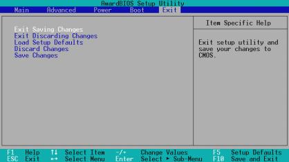
52 MAIN ADVANCED POWER BOOT EXIT <F1> or <Alt + H> <Esc> or<alt + X> or (keypad arrow) or (keypad arrows) - (minus key) + (plus key) or spacebar <Enter> <Home> or <PgUp> <End> or <PgDn> <F5> <F10> 52


53 53

54 54


55 55


56 56
57 57


58 58
59 CR2032 3V Lithium Cell CMOS Power CLRTC Short solder points to Clear CMOS A7PRO A7PRO Clear RTC RAM 59


60 60
61 61


62 62


63 63
64 64
65 65


66 66


67 67


68 68


69 69


70 70
71 71


72 72


73 73


74 74
75 75


76 76
77 77


78 78


79 79
80 80


81 81
82 82
83 83


84 84


85 85
86 86


87 LAN Activity Output Signal LEDs Intel Chipset RJ45 Wake on LAN Output Signal ASUS Motherboard type Other 97
88 98


89 Top: PHONE Bottom: LINE Codec Crystal 99


90 100
CUV4X. JumperFree TM PC-133 AGP/4X
 CUV4X JumperFree TM PC-133 AGP/4X 2 2000 3 4 5 6 7 8 9 10 11 12 1 2 3 4 5 6 7 25 24 23 22 21 20 19 18 17 16 15 14 13 12 11 10 9 8 13 20.9cm (8.22in) PS/2 VIO CPU_FAN Socket 370 cyrix 133 VIA VT82C694X
CUV4X-E. JumperFree TM PC-133/VC MHz FSB AGP PRO/4X Socket 370
 CUV4X-E JumperFree TM PC-133/VC133 133MHz FSB AGP PRO/4X Socket 370 2 2000 3 4 5 6 7 8 9 10 11 12 1 2 3 4 567 8 24 23 22 21 20 19 18 17 16 15 14 13 12 11 10 9 13 20.9cm (8.22in) PS/2 VIO USB COM1 LED Socket
A7A266-E DDR RAM/SDRAM 266MHz FSB AGP Pro/4X Socket A
 A7A266-E DDR RAM/SDRAM 266MHz FSB AGP Pro/4X Socket A 2 2001 3 4 5 6 7 8 9 10 11 / 12 1 2 3 4 5 6 7 27 26 25 24 23 22 21 20 19 18 17 16 15 14 131211 109 8 13 24.5cm (9.64in) PS/2 CPU_FAN USB1 USB2 01 01
JumperFree TM CUA
 JumperFree TM CUA 2 2000 3 4 5 6 7 8 9 10 11 3D Graphics 12 1 2 3 4 5 6 7 8 27 26 25 24 23 22 21 20 19 18 17 16 15 14 13 12 11 109 13 21.3 cm (8.38 in) PS/2KBMS VIO USB 2MB SDRAM IC_ PWR_ FAN COM2 2MB
2 2001
 CUV266 Socket 370 2 2001 3 4 5 6 7 8 9 10 11 12 1 2 3 4 5 6 27 26 25 24 23 22 21 20 19 18 17 1615 14 13 1211109 8 7 13 24.5cm (9.64in) PS/2 USB1_PWR CUV266 USB RJ-45 COM1 JTPWR 0 1 01 3 4 01 01 5 6 VIO3
P4T533-C
 P4T533-C T1047 2002 ii iii iv v vi vii viii 1 2 2 3 Jumper Mode Jumper Free (Default) ix x xi xii 1 2 3 4 1 23 4 5 6 7 32 31 30 29 28 27 26 25 24 23 8 9 10 11 12 13 14 22 21 20 19 18 17 16 15 33 34 35
P4G8X P4G8X Deluxe P4G8X
 P4G8X P4G8X Deluxe P4G8X Motherboard T1133 2002 2 3 4 5 6 7 8 1 2 2 3 Jumper Mode Jumper Free (Default) 9 10 11 12 1-1 1-2 1-3 1-4 1-5 1-6 1 2 3 4 5 6 7 8 21 20 19 9 10 18 17 16 1514 13 12 11 22 23 24
K1140A. December Checklist. Copyright 2002 ASUSTeK COMPUTER INC. All Rights Reserved.
 P4PE Motherboard Checklist K1140A December 2002 Copyright 2002 ASUSTeK COMPUTER INC. All Rights Reserved. ii Contents Features iii Safeguards Contents iv Contents v vi vii viii ix x P4PE xi xii P4PE Chapter
P4B533-E. Motherboard
 P4B533-E Motherboard T986 2002 2 3 4 5 6 7 8 1 2 2 3 Jumper Mode Jumper Free (Default) 9 10 11 12 1-1 1-2 1-3 1-4 1-5 1-6 1 2 3 4 5 6 7 23 22 8 9 10 21 20 11 12 19 13 18 17 16 15 14 24 25 26 27 28 29
P4B533-X. Motherboard
 P4B533-X Motherboard C1458 2003 2 3 4 5 6 7 1 2 2 3 Jumper Mode Jumper Free (Default) 8 9 10 1-1 1-2 1-3 1-4 SB_PWR1 P4B533-X P4B533-X Onboard LED ON Standby Power OFF Powered Off 1-5 CPU_FAN1 ATX12V1
A7V8X-MX. Motherboard
 A7V8X-MX Motherboard T1397 2003 ii iii iv v vi A7V8X-MX-TAYZ 10839 11036 6 0 12XX56XX90 vii viii ix x 1-1 1-2 TM 1 2 3 4 5 6 7 8 14 13 9 10 12 11 15 16 17 18 19 20 25 24 23 22 21 1-3 1-4 1-5 24.5cm (9.6in)
1. FEATURES. 1.1 The A7V-VM Motherboard
 1. FEATURES 1.1 The Motherboard The motherboard is carefully designed for the demanding PC user who wants high-performance features in a small package. 1.1.1 Specifications AMD Athlon /Duron Processor
A7V USER S MANUAL. Socket A Motherboard. JumperFree PC133/VC MHz FSB AGP Pro/4X
 A7V JumperFree PC133/VC133 200MHz FSB AGP Pro/4X Socket A Motherboard USER S MANUAL USER'S NOTICE No part of this manual, including the products and software described in it, may be reproduced, transmitted,
P4S800D-X. Motherboard
 P4S800D-X Motherboard T1753 2004 2 3 4 5 P4S800D-X-TAYZ 6 10839 11036 0 11XX11XX11 6 7 8 1-1 1-2 1-3 SB_PWR1 P4S800D-X P4S800D-X Onboard LED ON Standby Power OFF Powered Off 1-4 R 24.5cm (9.6in) PWR_FAN1
2. FEATURES. 2.1 The CUV-NT
 Specifications 2. FEA TURES 2. FEATURES 2.1 The The motherboard is carefully designed for the demanding PC user who wants advanced features processed by the fastest processors. 2.1.1 Specifications Latest
P4V800-X. Motherboard
 P4V800-X Motherboard C1371 2003 2 3 4 5 6 TM 1 2 2 3 Jumper Mode Jumper Free (Default) 7 8 9 10 1-1 1-2 1-3 1 2 3 4 5 6 16 8 7 15 14 13 9 10 12 17 11 18 19 20 21 22 27 26 25 24 23 1-4 1-5 1-6 1-7 19.3cm
1. FEATURES. 1.1 The CUW-AM
 Specifications 1. FEA TURES 1. FEATURES 1.1 The The motherboard is carefully designed for the demanding PC user who wants advanced features processed by the fastest processors. 1.1.1 Specifications Latest
K7V Slot A Motherboard USER S MANUAL
 R K7V Slot A Motherboard USER S MANUAL USER'S NOTICE No part of this manual, including the products and software described in it, may be reproduced, transmitted, transcribed, stored in a retrieval system,
MEL Socket 370 Motherboard USER S MANUAL
 R MEL Socket 370 Motherboard USER S MANUAL USER'S NOTICE No part of this manual, including the products and software described in it, may be reproduced, transmitted, transcribed, stored in a retrieval
6SMM7 USER'S MANUAL. Celeron TM Socket 370 Processor MAINBOARD REV. 1.1 First Edition R
 USER'S MANUAL. System power on by Keyboard: If your ATX power supply supports larger than 00 ma 5V Stand-By current (dependent on the specification of keyboards), you can power on your system by entering
P4P800-X. Motherboard
 P4P800-X Motherboard 2 C1718 3 4 5 6 1 2 2 3 Jumper Mode Jumper Free (Default) 7 8 9 10 1-1 1-2 1-3 SB_PWR P4P800-X P4P800-X Onboard LED ON Standby Power OFF Powered Off 1-4 20.8cm (8.2in) CPU_FAN ATX12V
Motherboard Specifications, A8AE-LE (AmberineM)
") 1 of 7 6/28/2009 11:14 PM» Return to original page Motherboard Specifications, A8AE-LE (AmberineM) Motherboard specifications table Motherboard layout and photos Clearing the CMOS settings Clearing the
1 of 7 6/28/2009 11:14 PM» Return to original page Motherboard Specifications, A8AE-LE (AmberineM) Motherboard specifications table Motherboard layout and photos Clearing the CMOS settings Clearing the
P4PE2-X. Motherboard
 P4PE2-X Motherboard C1788 2004 2 3 4 5 6 7 1 2 2 3 Jumper Mode Jumper Free (Default) 8 9 10 1-1 1-2 1-3 SB_PWR P4PE2-X P4PE2-X Onboard LED ON Standby Power OFF Powered Off 1-4 CPU_FAN ATX12V SPDIF_O COM1
CLK. Slot1 VIA ATX Mainboard. User s Manual 4
 2.1. Mainboard Layout Drawing CLK AGP 1 H14.318 Slot1 VIA693-133 ATX Mainboard ISA2 ISA1 User s Manual 4 2.2. Hardware Installation Steps 2.2.1. Installing System Memory The mainboard is equipped with
A7M266. DDR SDRAM 266MHz FSB AGP Pro/4X Socket A Motherboard USER S MANUAL
 A7M266 DDR SDRAM 266MHz FSB AGP Pro/4X Socket A Motherboard USER S MANUAL USER'S NOTICE No part of this manual, including the products and software described in it, may be reproduced, transmitted, transcribed,
6BA USER'S MANUAL. For Intel Pentium II / III / Celeron Processor MAINBOARD REV. 3.0 First Edition R
 USER'S MANUAL. System power on by PS/2 Mouse: First, enable this function in CMOS Setup, then you can power on the system by double clicking the right or left button of your PS/2 Mouse. 2. System power
Chapter 2 HARDWARE INSTALLATION. 2.1 Central Processing Unit: CPU CHAPTER 2
 Chapter 2 HARDWARE INST 2.1 Central Processing Unit: CPU The mainboard operates with Intel Pentium II/Celeron TM processor. The mainboard uses a CPU Slot called Slot 1 for easy CPU installation and a jumper
A7A266. DDR SDRAM 266MHz FSB AGP Pro/4X Socket A Motherboard USER S MANUAL
 A7A266 DDR SDRAM 266MHz FSB AGP Pro/4X Socket A Motherboard USER S MANUAL USER'S NOTICE No part of this manual, including the products and software described in it, may be reproduced, transmitted, transcribed,
Chapter 1 Specification
 SL-I / I-L Chapter Specifications COM LPT Chapter Specification - Mainboard Layout and Components Setup CPU Fan Analog Monitor Front Audio CD-ROM Audio LAN Controller (for I-L) ne in CD AC'97 IT872F JKB
K8N-E Deluxe. Motherboard
 K8N-E Deluxe Motherboard C1581 2004 ii iii iv v vi vii viii ix 1 2 2 3 Jumper Mode Jumper Free (Default) x xi xii 1-1 1-2 1-3 1-4 1-5 1-6 SB_PWR K8V-E K8N-E Onboard LED ON Standby Power OFF Powered
X533. User Manual. Version 1.0 Published April 2003 Copyright 2003 ASRock INC. All rights reserved.
 X533 User Manual Version 1.0 Published April 2003 Copyright 2003 ASRock INC. All rights reserved. 1 Copyright Notice: No part of this manual may be reproduced, transcribed, transmitted, or translated in
6BMM USER'S MANUAL. 3. Support Modem Ring-On. (Include internal Modem and external modem on COM A and COM B)
") USER'S MANUAL. System power on by PS/2 Mouse: First, enable this function in CMOS Setup, then you can power on the system by double clicking the right or left button of your PS/2 Mouse. 2. System power
USER'S MANUAL. System power on by PS/2 Mouse: First, enable this function in CMOS Setup, then you can power on the system by double clicking the right or left button of your PS/2 Mouse. 2. System power
TABLE OF CONTENTS 1. INTRODUCTION 2. SPECIFICATION 3. HARDWARE INSTALLATION 6BA
 6BA TABLE OF CONTENTS 1. INTRODUCTION 1.1. PREFACE...1-1 1.2. KEY FEATURES...1-1 1.3. PERFORMANCE LIST...1-2 1.4. BLOCK DIAGRAM...1-3 1.5. INTRODUCE THE Pentium II / III Processor...1-4 1.6. What is AGP?...1-5
TABLE OF CONTENTS 1. INTRODUCTION 2. SPECIFICATION 3. HARDWARE INSTALLATION. Table of Contents 1.1. PREFACE KEY FEATHERS...
 Table of Contents TABLE OF CONTENTS 1. INTRODUCTION 1.1. PREFACE... 1-1 1.2. KEY FEATHERS... 1-1 1.3. PERFORMANCE LIST... 1-2 1.4. BLOCK DIAGRAM... 1-3 1.5. INTRODUCE THE PENTIUM II/ III PROCESSORS...
M266A. User Manual. Version 1.0 Published April 2003 Copyright 2003 ASRock INC. All rights reserved.
 M266A User Manual Version 1.0 Published April 2003 Copyright 2003 ASRock INC. All rights reserved. 1 Copyright Notice: No part of this manual may be reproduced, transcribed, transmitted, or translated
686BX USER'S MANUAL. 3. Supports 3 steps ACPI LED. 4. Modem Ring-On. (COM B) 5. Wake-Up on LAN. (on J13) 6. Supports LDCM
 5. Wake-Up on LAN. (on J13) 6. Supports LDCM") 686BX USER'S MANUAL. System power on by PS/2 Mouse: First, enable this function in CMOS Setup, then you can power on the system by double clicking the right or left button of your PS/2 Mouse. 2. System
686BX USER'S MANUAL. System power on by PS/2 Mouse: First, enable this function in CMOS Setup, then you can power on the system by double clicking the right or left button of your PS/2 Mouse. 2. System
PE Pro-HT. User Manual. Version 1.0 Published January 2003 Copyright 2003 ASRock INC. All rights reserved.
 PE Pro-HT User Manual Version 1.0 Published January 2003 Copyright 2003 ASRock INC. All rights reserved. 1 Copyright Notice: No part of this manual may be reproduced, transcribed, transmitted, or translated
CUSL-L. Intel 815 microatx Motherboard USER S MANUAL
 Intel 815 microatx Motherboard USER S MANUAL USER'S NOTICE No part of this manual, including the products and software described in it, may be reproduced, transmitted, transcribed, stored in a retrieval
TABLE OF CONTENTS 1. INTRODUCTION 2. SPECIFICATION 3. HARDWARE INSTALLATION 6BMM 1.1. PREFACE KEY FEATURES...1-1
 6BMM TABLE OF CONTENTS 1. INTRODUCTION 1.1. PREFACE...1-1 1.2. KEY FEATURES...1-1 1.3. PERFORMANCE LIST...1-2 1.4. BLOCK DIAGRAM...1-3 1.5. INTRODUCE THE Pentium II Processor & AGP...1-4 1.6. What is AGP?...1-6
CUW-RM Intel 810 microatx Motherboard USER S MANUAL
 CUW-RM Intel 810 microatx Motherboard USER S MANUAL USER'S NOTICE No part of this manual, including the products and software described in it, may be reproduced, transmitted, transcribed, stored in a retrieval
K7VM2. User Manual. Version 3.1 Published July 2003 Copyright 2003 ASRock INC. All rights reserved.
 K7VM2 User Manual Version 3. Published July 2003 Copyright 2003 ASRock INC. All rights reserved. Copyright Notice: No part of this manual may be reproduced, transcribed, transmitted, or translated in any
Pentium. P2B-F II Motherboard USER S MANUAL
 Pentium R P2B-F II Motherboard USER S MANUAL Product Name: ASUS P2B-F Manual Revision: 1.00 E277 Release Date: October1998 USER'S NOTICE No part of this manual, including the products and software described
P3C2000 JumperFree ATX Motherboard USER S MANUAL
 R P3C2000 JumperFree ATX Motherboard USER S MANUAL USER'S NOTICE No part of this manual, including the products and software described in it, may be reproduced, transmitted, transcribed, stored in a retrieval
M2N68-LA (Narra 3) Motherboard
 Motherboard") (Narra 3) Motherboard E3503 First Edition V1 October 2007 Contents (Narra 3) specifications summary... iii 1. Motherboard layout... 1 2. Central Processing Unit (CPU)... 2 2.1 Overview... 2 2.2 Installing
(Narra 3) Motherboard E3503 First Edition V1 October 2007 Contents (Narra 3) specifications summary... iii 1. Motherboard layout... 1 2. Central Processing Unit (CPU)... 2 2.1 Overview... 2 2.2 Installing
K7VT4A+ User Manual. Version 1.0 Published May 2004 Copyright 2004 ASRock INC. All rights reserved.
 K7VT4A+ User Manual Version.0 Published May 2004 Copyright 2004 ASRock INC. All rights reserved. Copyright Notice: No part of this manual may be reproduced, transcribed, transmitted, or translated in any
P2V Pentium II/Celeron Motherboard USER S MANUAL
 P2V Pentium II/Celeron Motherboard USER S MANUAL Product Name: ASUS P2V Manual Revision: 1.01 E384 Release Date: May 1999 USER'S NOTICE No part of this manual, including the products and software described
A7N266. JumperFree DDR DRAM 266MHz FSB NVIDIA nforce 420 Chipset Socket A Motherboard USER S MANUAL
 A7N266 JumperFree DDR DRAM 266MHz FSB NVIDIA nforce 420 Chipset Socket A Motherboard USER S MANUAL USER'S NOTICE No part of this manual, including the products and software described in it, may be reproduced,
Pentium. P2B-B II/Celeron TM Motherboard USER S MANUAL
 Pentium R P2B-B II/Celeron TM Motherboard USER S MANUAL Product Name: ASUS P2B-B Manual Revision: 1.02 E309 Release Date: December1998 USER'S NOTICE No part of this manual, including the products and software
TABLE OF CONTENTS 1. INTRODUCTION 2. SPECIFICATION 3. HARDWARE INSTALLATION 6LX7 / 6LX7A 1.1. PREFACE KEY FEATHERS...
 TABLE OF CONTENTS 1. INTRODUCTION 1.1. PREFACE...1-1 1.2. KEY FEATHERS...1-1 1.3. PERFORMANCE LIST...1-3 1.4. BLOCK DIAGRAM...1-4 1.5. INTRODUCE THE INTEL Celeron TM Socket 370 Processor...1-5 1.6. WHAT
TABLE OF CONTENTS 1. INTRODUCTION 2. SPECIFICATION 3. HARDWARE INSTALLATION 6BXDS 1.1. PREFACE KEY FEATURES...1-1
 6BXDS 1. INTRODUCTION TABLE OF CONTENTS 1.1. PREFACE...1-1 1.2. KEY FEATURES...1-1 1.3. PERFORMANCE LIST...1-2 1.4. BLOCK DIAGRAM...1-3 1.5. INTRODUCE THE Pentium II Processor...1-4 1.6. What is AGP?...1-6
Quick Start Guide. SY-6BB V1.0 Mainboard F C. Introduction. Installation. Hardware. Quick BIOS Setup. The SOYO CD
 SY-6BB V.0 Mainboard Quick Start Guide Introduction Hardware Installation Quick BIOS Setup The SOYO CD F C Tested To Comply With FCC Standards FOR HOME OR OFFICE USE POST CONSUMER 00% RECYCLED PAPER SOYO
TABLE OF CONTENTS 1. INTRODUCTION 2. SPECIFICATION 3. HARDWARE INSTALLATION 6VX PREFACE KEY FEATHERS
 6VX7 TABLE OF CONTENTS 1. INTRODUCTION 1.1. PREFACE... 1-1 1.2. KEY FEATHERS... 1-1 1.3. PERFORMANCE LIST... 1-2 1.4. BLOCK DIAGRAM... 1-3 1.5. INTRODUCE THE INTEL Celeron TM Socket 370 Processor... 1-4
FAN3 Connector AUX-IN Connector. CD-IN Connector FAN2 Connector. Intel /100 LAN Controller CPU2 FAN Connector AGP Pro Slot USB Connector
 PS/2 Mouse Connector SPP/EPP/ECP Parallel Port RJ45 0/00 LAN Jack (Optional) Speaker Out FAN3 Connector AUX-IN Connector PS/2 Keyboard Connector USB Port Port 2 Port Line-In MIC-In CD-IN Connector FAN2
TABLE OF CONTENTS 1. INTRODUCTION 2. SPECIFICATION 3. HARDWARE INSTALLATION 6EX 1.1. PREFACE KEY FEATURES PERFORMANCE LIST...
 6EX TABLE OF CONTENTS 1. INTRODUCTION 1.1. PREFACE...1-1 1.2. KEY FEATURES...1-1 1.3. PERFORMANCE LIST...1-2 1.4. BLOCK DIAGRAM...1-3 1.5. INTRODUCE THE Pentium II Processor & AGP...1-4 1.6 What is AGP?...
P2-99B Pentium III / II / Celeron TM Motherboard USER S MANUAL
 R P2-99B Pentium III / II / Celeron TM Motherboard USER S MANUAL Product Name: ASUS P2-99B Manual Revision: 1.01 E388 Release Date: May 1999 USER'S NOTICE No part of this manual, including the products
TABLE OF CONTENTS 1. INTRODUCTION 2. SPECIFICATION 3. HARDWARE INSTALLATION. Table Of Contents 1.1. PREFACE KEY FEATURES...
 Table Of Contents TABLE OF CONTENTS 1. INTRODUCTION 1.1. PREFACE...1-1 1.2. KEY FEATURES...1-1 1.3. PERFORMANCE LIST...1-2 1.4. BLOCK DIAGRAM...1-3 1.5. INTRODUCE THE Pentium II Processor & AGP...1-4 1.6.
Chapter 1. Getting Started Getting Started
 Getting Started Chapter 1. Getting Started Getting Started 1 Thank you for purchasing the MS-6579 (v1.x) M-ATX mainboard. The MS-6579 mainboard is based on Intel Brookdale-E GMCH & ICH4 chipsets for optimal
C ii
 K8S-MX Motherboard C1647 2004 ii iii iv v vi vii 1 2 2 3 Jumper Mode Jumper Free (Default) viii ix x 1-1 1-2 1-3 1-4 SB_PWR K8S-MX K8S-MX Onboard LED ON Standby Power OFF Powered Off 1-5 R 19.3cm (7.6in)
TUSL2-M Intel 815E Chipset microatx Motherboard USER S MANUAL
 TUSL2-M Intel 815E Chipset microatx Motherboard USER S MANUAL USER'S NOTICE No part of this manual, including the products and software described herein, may be reproduced, transmitted, transcribed, stored
TABLE OF CONTENTS 1. INTRODUCTION 2. SPECIFICATION 3. HARDWARE INSTALLATION. Table of Contents 1.1. PREFACE KEY FEATURES...
 Table of Contents TABLE OF CONTENTS 1. INTRODUCTION 1.1. PREFACE...1-1 1.2. KEY FEATURES...1-1 1.3. PERFORMANCE LIST...1-2 1.4. BLOCK DIAGRAM...1-3 1.5. INTRODUCE THE INTEL Celeron TM Socket 370 Processor...1-4
TABLE OF CONTENTS 1. INTRODUCTION 2. SPECIFICATION 3. HARDWARE INSTALLATION 6EM 1.1. PREFACE KEY FEATURES PERFORMANCE LIST...
 6EM TABLE OF CONTENTS 1. INTRODUCTION 1.1. PREFACE...1-1 1.2. KEY FEATURES...1-1 1.3. PERFORMANCE LIST...1-2 1.4. BLOCK DIAGRAM...1-3 1.5. INTRODUCE THE Pentium II Processor & AGP...1-4 1.6 What is AGP?...1-6
Pentium. SP98AGP-X ATX Motherboard USER S MANUAL
 Pentium R SP98AGP-X ATX Motherboard USER S MANUAL USER S NOTICE No part of this manual, including the products and software described in it, may be reproduced, transmitted, transcribed, stored in a retrieval
Assignment 5. You can configure hardware options by setting jumper on the mainboard. See Figure 2-1 for jumper locations. Set a jumper as follows:
 CIS 170 Microcomputer Hardware Name: Assignment 5 From the lack of having enough peripherals for this course (at least at this point), we have the necessity of doing some experiments mentally rather than
Colorful Technology Website:
 Colorful Technology Website: http://www.colorful.cn Thanks for purchasing our based on Intel B250 Chipset motherboard. The motherboard C.B250A-BTC PLUS V20 based on Intel B250 Express Chipset, support
P3B-F Pentium III / II / Celeron TM Motherboard USER S MANUAL
 P3B-F Pentium III / II / Celeron TM Motherboard USER S MANUAL Product Name: ASUS P3B-F Manual Revision: 1.04 E467 Release Date: October 1999 USER'S NOTICE No part of this manual, including the products
6BXC USER'S MANUAL. 3. Supports 3 steps ACPI LED. 4. Modem Ring-On. (COM A, B).
.") USER'S MANUAL. System power on by PS/2 Mouse: First, enable this function in CMOS Setup, then you can power on the system by double clicking the right or left button of your PS/2 Mouse. 2. System power
USER'S MANUAL. System power on by PS/2 Mouse: First, enable this function in CMOS Setup, then you can power on the system by double clicking the right or left button of your PS/2 Mouse. 2. System power
TABLE OF CONTENTS 1. INTRODUCTION 2. SPECIFICATION 3. HARDWARE INSTALLATION 6VMA 1.1. PREFACE KEY FEATURES...1-1
 6VMA TABLE OF CONTENTS 1. INTRODUCTION 1.1. PREFACE...1-1 1.2. KEY FEATURES...1-1 1.3. PERFORMANCE LIST...1-2 1.4. BLOCK DIAGRAM...1-3 1.5. INTRODUCE THE Pentium II / III Processor...1-4 1.6. What is AGP?...1-5
5AMMC USER'S MANUAL. Support Intel Pentium, MMX, Cyrix/IBM 6x86MX, MII, AMD K5, K6, K6-2 & IDT C6 CPUs. Support auto detect CPU Voltage.
 5AMMC USER'S MANUAL Support Intel Pentium, MMX, Cyrix/IBM 6x86MX, MII, AMD K5, K6, K6-2 & IDT C6 s. Support auto detect Voltage. Support Parity check or Ecc Function. Support Fully.0 Specification. Support
Pentium. P2L97 II Motherboard USER S MANUAL
 Pentium R P2L97 II Motherboard USER S MANUAL Product Name: ASUS P2L97 Manual Revision: 2.05 E266 Release Date: October 1998 USER'S NOTICE No part of this manual, including the products and software described
TABLE OF CONTENTS 1. INTRODUCTION 1.1. PREFACE KEY FEATURES PERFORMANCE LIST BLOCK DIAGRAM...
 TABLE OF CONTENTS 1. INTRODUCTION 1.1. PREFACE... 1-1 1.2. KEY FEATURES... 1-1 1.3. PERFORMANCE LIST... 1-3 1.4. BLOCK DIAGRAM... 1-4 1.5. INTRODUCE THE PCI - BUS... 1-5 1.6. FEATURES... 1-5 2. SPECIFICATION
CUW(E)-FX Intel 810 FlexATX Motherboard USER S MANUAL
-FX Intel 810 FlexATX Motherboard USER S MANUAL") CUW(E)-FX Intel 810 FlexATX Motherboard USER S MANUAL Special Features CUWE-FX Intel 810E Chipset with support for 133/100/66MHz FSB 4MB 32-bit 133MHz SDRAM display cache onboard CUW-FX Intel 810 Chipset
CUW(E)-FX Intel 810 FlexATX Motherboard USER S MANUAL Special Features CUWE-FX Intel 810E Chipset with support for 133/100/66MHz FSB 4MB 32-bit 133MHz SDRAM display cache onboard CUW-FX Intel 810 Chipset
User s Manual Full-Size PICMG 1.3 SHB Version 1.0
 3308360 User s Manual Full-Size PICMG 1.3 SHB Version 1.0 Copyrights This document is copyrighted and all rights are reserved. It does not allow any non authorization in copied, photocopied, translated
Computer Maintenance. PC Disassembly and Reassembly. Copyright Texas Education Agency, All rights reserved.
 Computer Maintenance PC Disassembly and Reassembly 1 Enabling Objectives Computer Chassis (Cases) Power Supplies Configuring the Motherboard Configuring the Connectors CPU Interfaces RAM Installing a Hard
ME-99B Socket 370 Baby AT Motherboard USER S MANUAL
 R ME-99B Socket 370 Baby AT Motherboard USER S MANUAL Product Name: ASUS ME-99B Manual Revision: 1.01 E403 Release Date: June 1999 USER'S NOTICE No part of this manual, including the products and software
Electronic Emission Notices
 Electronic Emission Notices Federal Communications Commission (FCC) Statement This equipment has been tested and found to comply with the limits for a Class B digital device, pursuant to Part 5 of FCC
EVGA assumes you have purchased all necessary parts needed to allow for proper system functionality.
 Before You Begin Parts NOT in the Kit This kit contains all the hardware necessary to install and connect your new EVGA e-7050/610i GPU motherboard with integrated GeForce graphics processing. However,
P2B-D / P2B-DS USER S MANUAL
 R P2B-D / P2B-DS Dual Pentium II Motherboards USER S MANUAL Special Features P2B-DS Adaptec 7890 SCSI Chipset Adaptec 3860 SCSI Transceiver USER'S NOTICE No part of this manual, including the products
K7V88. User Manual. Version 1.0 Published March 2004 Copyright 2004 ASRock INC. All rights reserved.
 K7V88 User Manual Version.0 Published March 2004 Copyright 2004 ASRock INC. All rights reserved. Copyright Notice: No part of this manual may be reproduced, transcribed, transmitted, or translated in any
K7Upgrade-880. User Manual. Version 1.0 Published August 2004 Copyright 2004 ASRock INC. All rights reserved.
 K7Upgrade-880 User Manual Version.0 Published August 2004 Copyright 2004 ASRock INC. All rights reserved. Copyright Notice: No part of this manual may be reproduced, transcribed, transmitted, or translated
Mainboard Series SL-85DRV User Manual V1.1 SL-85DRV SL-85DRV + SL-85DRV-X SL-85DRV + -X
 R T h e S o u l O f C o m p u t e r T e c h n o l o g y Mainboard Series SL-85DRV User Manual V. SL-85DRV SL-85DRV + SL-85DRV-X SL-85DRV + -X Series SL-85DRV NOTICE TmPGA478B Product Model : Series SL-85DRV
P4SE. User Guide. Motherboard
 P4SE User Guide Motherboard Checklist E1141 Second Edition October 2002 Copyright 2002 ASUSTeK COMPUTER INC. All Rights Reserved. No part of this manual, including the products and software described in
P2V-B Pentium III / II / Celeron TM Motherboard USER S MANUAL
 R P2V-B Pentium III / II / Celeron TM Motherboard USER S MANUAL Product Name: ASUS P2V-B Manual Revision: 1.02 E353 Release Date: March 1999 USER'S NOTICE No part of this manual, including the products
Getting Started. Chapter 1. Introduction. Chapter 1. Getting Started
 Introduction Chapter. Introduction Chapter. Getting Started Getting Started Thank you for purchasing the MS-6367 v.x M-ATX mainboard. The MS-6367 mainboard is a superior computer mainboard based on nvidia
6VXE USER'S MANUAL. 3. Supports 3 steps ACPI LED. 4. Modem Ring-On. (COM A, B).
.") USER'S MANUAL. System power on by PS/2 Mouse: First, enable this function in CMOS Setup, then you can power on the system by double clicking the right or left button of your PS/2 Mouse. 2. System power
USER'S MANUAL. System power on by PS/2 Mouse: First, enable this function in CMOS Setup, then you can power on the system by double clicking the right or left button of your PS/2 Mouse. 2. System power
VI31 MAINBOARD MANUAL. Date : 1, 2002 PCB : 2.2 (for HP)
") VI31 MAINBOARD MANUAL Date : 1, 2002 PCB : 2.2 (for HP) Table of Contents Table of Contents Chapter 1 Overview The VI31 Mainboard... 1-2 Main Features... 1-3 Chapter 2 Installation Procedures Quick Reference
VI31 MAINBOARD MANUAL Date : 1, 2002 PCB : 2.2 (for HP) Table of Contents Table of Contents Chapter 1 Overview The VI31 Mainboard... 1-2 Main Features... 1-3 Chapter 2 Installation Procedures Quick Reference
P5RD1-VM. Motherboard
 P5RD1-VM Motherboard T2440 2006 2 3 4 5 6 7 1 2 2 3 Jumper Mode Jumper Free (Default) P5RD1VM-TAYZ 10839 11036 6 0 11XX11XX11 8 9 10 1-1 1-2 1-3 1-4 P5RD1-VM LED1 P5RD1-VM Onboard LED ON Standby Power
Mainboard User s Manual
 This publication, including all photographs, illustrations and software, is protected under international copyright laws, with all rights reserved. Neither this manual, nor any of the material contained
MEZ-VM Socket 370 AGP Motherboard USER S MANUAL
 R MEZ-VM Socket 370 AGP Motherboard USER S MANUAL USER'S NOTICE No part of this manual, including the products and software described in it, may be reproduced, transmitted, transcribed, stored in a retrieval
P3B-1394 IEEE-1394 Motherboard USER S MANUAL
 P3B-1394 IEEE-1394 Motherboard USER S MANUAL Product Name: ASUS P3B-1394 Manual Revision: 2.02 E455 Release Date: September 1999 USER'S NOTICE No part of this manual, including the products and software
MES-VM Socket 370 microatx Motherboard USER S MANUAL
 R MES-VM Socket 370 microatx Motherboard USER S MANUAL USER'S NOTICE No part of this manual, including the products and software described in it, may be reproduced, transmitted, transcribed, stored in
P5A-VM Super7 microatx Motherboard USER S MANUAL
 R P5A-VM Super7 microatx Motherboard USER S MANUAL USER'S NOTICE No part of this manual, including the products and software described in it, may be reproduced, transmitted, transcribed, stored in a retrieval
775V88/775V88+ User Manual. Version 1.0 Published December 2004 Copyright 2004 ASRock INC. All rights reserved.
 775V88/775V88+ User Manual Version 1.0 Published December 2004 Copyright 2004 ASRock INC. All rights reserved. 1 Copyright Notice: No part of this manual may be reproduced, transcribed, transmitted, or
TABLE OF CONTENTS 1. INTRODUCTION 2. SPECIFICATION 3. HARDWARE INSTALLATION. Table of Contents 1.1. PREFACE KEY FEATURES...
 Table of Contents TABLE OF CONTENTS 1. INTRODUCTION 1.1. PREFACE...1-1 1.2. KEY FEATURES...1-1 1.3. PERFORMANCE LIST...1-2 1.4. BLOCK DIAGRAM...1-3 1.5. INTRODUCE THE Pentium II/III Processor...1-4 1.6.
A7N8X-X. User Guide. Motherboard
 A7N8X-X User Guide Motherboard Checklist E1294 First Edition April 2003 Copyright 2003 ASUSTeK COMPUTER INC. All Rights Reserved. No part of this manual, including the products and software described in
P4i48. User Manual. Version 1.0 Published February 2004 Copyright 2004 ASRock INC. All rights reserved.
 P4i48 User Manual Version 1.0 Published February 2004 Copyright 2004 ASRock INC. All rights reserved. 1 Copyright Notice: No part of this manual may be reproduced, transcribed, transmitted, or translated
P5VD1-X. Motherboard
 P5VD1-X Motherboard T2180 2005 2 3 4 5 6 7 1 2 2 3 Jumper Mode Jumper Free (Default) 8 P5GD1-TAYZ 10839 11036 6 0 11XX11XX11 9 10 11 12 1-1 1-2 1-3 1-4 SB_PWR P5VD1-X P5VD1-X Onboard LED ON Standby
TUWE-M Intel 810E2 MicroATX Motherboard USER S MANUAL
 TUWE-M Intel 810E2 MicroATX Motherboard USER S MANUAL USER'S NOTICE No part of this manual, including the products and software described in it, may be reproduced, transmitted, transcribed, stored in a
CPU fan has a power connector which needs to be connected to CPU fan power socket on your motherboard as shown on the image above.
 The first thing you should do is unpack your ATX case. Take off the cover of your case so that you can access the inside. Place the case on a desk so that you are looking down towards the open case. Your
1.1.Packing Contents 1*Colorful C.B250A-BTC V20 motherboard 2*SATA cables 1*Driver/Utility CD 1*User's Guide 1*I/O shield 1.2.MOTHERBOARD SPEC CPU
 Colorful Technology Website: http://www.colorful.cn Thanks for purchasing our based on Intel B250 Chipset motherboard. The motherboard C.B250A-BTC V20 based on Intel B250 Express Chipset, support Intel
P4VT8+ User Manual. Version 1.0 Published January 2004 Copyright 2004 ASRock INC. All rights reserved.
 P4VT8+ User Manual Version 1.0 Published January 2004 Copyright 2004 ASRock INC. All rights reserved. 1 Copyright Notice: No part of this manual may be reproduced, transcribed, transmitted, or translated