AT&T Issue 1. StarServer S User's Guide
|
|
|
- Junior Cain
- 6 years ago
- Views:
Transcription


1 AT&T Issue 1 StarServer S User's Guide
2 System Description 1 This chapter introduces the features and capabilities of the AT&T StarServer S. Before installing the StarServer S, please read this chapter and familiarize yourself with the following: Important system features The system configuration The optional expansion kits available for the system Summary of System Features The AT&T StarServer S is a high-performance, Extended Industry Standard Architecture (EISA)-compatible system operating at a clock speed of 33 MHz. Developed using Intel's i486 microprocessor, the AT&T StarServer S is more advanced and far more versatile than earlier systems. The system's design provides substantially faster processing speed, greater storage capacity, and greater multitasking functionality. The AT&T StarServer S maintains compatibility with software created for previous microprocessors such as the 8088, 8086, 80286, and By providing the ability to simulate slower system speeds, the AT&T StarServer S ensures that timing-dependent and copy-protected applications operate without modification. AT&T StarServer S User's Guide 1-1
3 System Description The combination of high-speed processing and greater memory capacity allows the StarServer S to easily accommodate the needs of memory-intensive software, such as large spreadsheet and database applications, computer-aided design/computer-aided engineering (CAD/CAE) applications, multiuser and multitasking operating systems, telecommunications, and network servers. If your application requirements increase, you can easily upgrade the StarServer S with a variety of expansion boards, peripheral devices, video and graphic devices, floppy and hard disk drives, and streaming tape units (STUs). The Basic System Configuration The StarServer S consists of three major modules, as illustrated in Figure 1: The system module (1,A) The keyboard (1,B) The video display (1,C) (optional) System Module The system module contains the system board, slots for expansion boards, internal magnetic peripherals, and a power supply. The high performance features of the StarServer S include: A 33 MHz central processing unit (CPU) A base configuration of four megabytes of onboard system random access memory (RAM). The system can be expanded to 64MB of RAM. A 128KB external cache 1-2 AT&T StarServer S User's Guide
4 System Description Extended Industry Standard Architecture (EISA) for high speed CPU, direct memory access (DMA), and I/O data transfers An EISA Small Computer System Interface (SCSI) host adapter with caching capabilities for high data throughput rates Support for a Weitek 4167 numeric coprocessor Shadow RAM for fast system basic input/output system (BIOS) and video BIOS access The StarServer S also features: Two 25-pin parallel ports Two 9-pin serial communication ports One mini-din keyboard interface One mini-din mouse interface One internal speaker One real-time clock/calendar complementary metal oxide semiconductor (CMOS) chip with integral lithium battery An 8KB non-volatile random access memory (NVRAM) chip Ten EISA expansion slots Support for 128KB erasable programmable read-only memory (EPROMs) System Module Configurations The StarServer S is offered in different system module configurations. These configurations include a 1.44MB (3.5-inch) floppy disk drive with either a 300MB or a 600MB hard disk drive. The system module configurations available include: CPU 362: 1.44MB (3.5-inch) floppy disk drive and a 300MB (5.25-inch) hard disk drive CPU 363: 1.44MB (3.5-inch) floppy disk drive and a 600MB (5.25-inch) hard disk drive AT&T StarServer S User's Guide 1-3
5 System Description System Module Controls and Indicators Figure 2 illustrates the front panel and the location of the following controls and indicators: Rest button (2,A). Use the reset button to reset the system module without turning the system off. Chassis lock (2,B). Turn the key to the locked position 8,B) to lock the system module cover onto the chassis. Hard disk drive access indicator (2,C). The indicator lights (amber) when a hard disk drive is being accessed. Power indicator (2,D). The indicator lights (green) when the system module power is on. Fault indicator (2,G). The indicator lights (amber) when the power-on self test (POST) is executing and remains lit if an error is found. Power switch (2,E). Use the power switch to turn the system module on and off. Floppy disk drive access indicator (2,F). The indicator lights (amber) when the drive is being accessed. Floppy disk drive release button (2,H). Use the floppy disk drive release button to release a floppy disk from drive A. Peripheral compartment lock (2,J). Turn the key to the locked position (8,A) to lock the peripheral compartment door. 1-4 AT&T StarServer S User's Guide
6 System Description System Module I/O Panel Cover The I/O panel cover provides access to the following connectors: Parallel interface connectors (3,E,F) Serial interface connectors (3,D,J) Mouse interface connector (3,C) Keyboard interface connector (3,B) Expansion board connectors (if installed) (3,A) To access the I/O panel and expansion board connectors, lift up on the rear of the I/O panel cover (3,G) located at the top-rear of the system. System Module Power Connections The rear panel provides an AC input power socket and a power outlet for the video display. These connectors are located at the bottom of the rear panel (4,D,F). System Memory RAM The StarServer S provides two types of memory: random access memory (RAM) and read only memory (ROM) (refer to Table 1-1 and Figure 5). RAM exists in two formats: conventional memory and extended memory. Conventional Memory Conventional memory is located within an address range of 00000H to 9FFFFH (640KB of memory). AT&T StarServer S User's Guide 1-5
7 System Description Table 1-1. System Memory Allocation Address Amount Usage 00000H to 7FFFFH 80000H to 9FFFFH A0000H to BFFFFH C0000H to C7FFFH C8000H to DFFFFH E0000H to FFFFFH F80000H to FFFFFFH H to 3FFFFFFH H to 0FFFFFFFH H to FFFFFFFFH 512KB 128KB 128KB 32KB 96KB 128KB 512KB 64MB 256MB 4GB Conventional (0-512KB) Conventional (512KB- 640KB) (enabled in SETUP utility) Video controller RAM for plug-in cards Video BIOS/video BIOS shadow for plug-in cards Available for expansion card ROM and RAM System BIOS/system BIOS shadow System BIOS/system BIOS shadow or RAM Maximum range of system memory User assigned attributes Physical addressing limit of the i486 CPU Extended Memory Extended memory is memory above H (one megabyte). Extended memory can be accessed only when the CPU is operating in protected mode. 1-6 AT&T StarServer S User's Guide
8 System Description Onboard RAM The system board contains four single in-line memory module (SIMM) banks. Each bank holds two SIMMs. The base configuration of the system is 4MB of RAM (two 2MB SIMMs); SIMMs must be installed in pairs of the same size. Each 2MB SIMM is double-sided and organized as 256K 36 bits per side. Each of the 36-bit sets comprises four independently-accessible 9-bit units consisting of eight bits of data and one parity bit. The system board also supports 8MB SIMMs. The 8MB SIMMs are double-sided and arranged as 1M 36 bits per side. The maximum system configuration is eight 8MB SIMMs (64MB). Note Both SIMM sizes can reside on the system board at the same time. However, you must install them in pairs and you must install them starting with the farthest vacant socket to the right. Refer to Appendix C, "Expansion Kits," for detailed information on installing SIMMs. ROM The system board ROM contains the BIOS, POST, and ROM-based SETUP. The ROM occupies the highest 128KB of the first megabyte (E0000H to FFFFFH) of memory. Shadow RAM An option is available that allows the system BIOS to be copied into RAM for faster ROM access. This option is referred to as "shadowing." In addition to shadowing system BIOS, a shadow option is also provided for video BIOS residing on the video display controller board. When ROM is copied into the RAM, the CPU accesses the BIOS at the same speed it accesses other RAM. The system board architecture makes sure the ROM data copied into the RAM is write-protected. This prevents inadvertent overwriting of BIOS information. AT&T StarServer S User's Guide 1-7
9 System Description ROM-Based SETUP Note All system setup parameters should be defined and modified using the EISA Configuration Utility (ECU). If you choose to use the ROM-based SETUP utility, conflicts between the Industry Standard Architecture (ISA) and EISA CMOS values can result in unpredictable system behavior. It is recommended that you do not use the ROM-based SETUP utility. The system ROM-based SETUP allows you to set a limited number of system options. Refer to Appendix B, "ROM-Based SETUP," for detailed information on using SETUP. 128KB External Cache The 128KB external cache module increases system performance by reducing the average number of wait states seen by the The external cache plugs into a socket on the system board (6,H). SCSI Interface The small computer system interface (SCSI) is a local I/O bus that provides a uniform interface for peripheral devices. You can add different disk drives, streaming tape units, printers, and communication devices to the system without having to modify the system's hardware or software. SCSI transfers much of the intelligence of the I/O interface to the controller on a peripheral device. This frees up the CPU to perform other tasks while the peripheral device is responding to a command. SCSI devices are connected using a common cable. Both ends of the cable are terminated and all signals are common to all devices. 1-8 AT&T StarServer S User's Guide
10 System Description Video Display The AT&T video display options for the StarServer S include VGA-compatible color displays and compatible video display controllers. These displays provide high resolution text and graphics modes. An instruction booklet, packed with each video display, shows the locations of the controls on the video display. These controls allow you to adjust the brightness and contrast of the screen. Keyboard The keyboard allows you to interact with the StarServer S by entering data or commands. The AT&T 305C keyboard (Figure 7) is a 101-key keyboard having a mini-din type connector (7,A). Chapter 4, "Operating Your System," describes the layout of the keyboard and explains how to use the different groups of keys. The coiled flexible cable (7,B) connects the keyboard to the system module. The keyboard also has adjustable feet allowing you to change its angle for comfortable typing. Expanding Your System You can expand the StarServer S by installing RAM, peripherals, and other options. Expansion capabilities include: A socket for a 33 MHz Weitek 4167 numeric coprocessor Sockets on the system board for additional onboard RAM AT&T StarServer S User's Guide 1-9
11 System Description Ten EISA expansion slots A peripheral device bay that holds up to four half-height and two full-height 5.25-inch peripheral devices Note Each system is also equipped with four extra pairs of drive mounting rails and four power connectors. Expansion Kits Several expansion options are available from AT&T in ready-to-install expansion kits. Refer to Appendix C, "Expansion Kits," for installation instructions. Also, contact your AT&T Sales Representative or authorized dealer for the latest information on expansion options and kits. Numeric Coprocessor Adding a 33 MHz Weitek 4167 numeric coprocessor increases the numeric processing performance of the StarServer S. The 4167 plugs into a socket on the system board (6,A). The 4167 performs mathematical computations faster than the built-in compatible coprocessor in the 80486, resulting in higher performance for math-intensive applications that support Weitek coprocessors, such as spreadsheets and graphics. System RAM You can expand system RAM (up to 64MB total RAM) by adding additional 4MB or 16MB increments of RAM in the system board SIMM sockets AT&T StarServer S User's Guide
12 System Description Additional Magnetic Peripherals You can add additional magnetic peripherals to the system module. These magnetic peripherals increase the storage capacity and flexibility of the StarServer S. The following AT&T magnetic peripherals are available: A 1.44MB 3.5-inch floppy disk drive A 1.2MB 5.25-inch floppy disk drive A 300MB, 600MB, or 1GB hard disk drive A 120MB or 320/525MB SCSI streaming tape unit System Security Your system contains the following security features: A system module chassis lock A peripheral compartment lock Password features Refer to Chapter 4, "Operating Your System," for instructions on using these system security features. Note Be careful not to lose the system keys. Losing the system keys prevents you from opening the locked peripheral compartment or removing the system module cover. Contact your AT&T Service Representative or authorized dealer for information on replacing lost keys. AT&T StarServer S User's Guide 1-11
13 Getting Started 3 This chapter provides information on how to set up and configure the AT&T StarServer S. This chapter explains: How to start the system What happens when the system starts the first time How to set up and configure the system using the StarServer S Configuration Utilities and the Extended Industry Standard Architecture (EISA) Configuration Utility (ECU) If this is the first time you are starting the system, use the ECU to initially configure it. If your system has already been configured, and you want to change system hardware or if the real-time clock chip or NVRAM have been replaced, run the ECU to configure the system for the new hardware and to set new system parameters. If the system does not operate as described in this chapter, refer to Chapter 5, "Problem Solving." If error messages appear on the screen, refer to Appendix G, "Messages," for possible causes and suggested solutions. AT&T StarServer S User's Guide 3-1
14 Getting Started Starting the System Start the system by performing the following: 1. Remove any drive protection card(s) (if present) from the floppy disk drive(s) (see Figure 18). 2. Turn on the video display Note Use the Copy Floppy Disk option from the System Configuration floppy disk and make a backup copy of the original System Configuration floppy disk. Store the original in a secure place and use only the backup copy when setting up and configuring the system. Insert the System Configuration floppy disk back-up copy into drive A. Turn on the system (2,E). Adjust the video display to obtain a readable screen display. (Refer to the video display manual for instructions.) Note You may have to enable or disable the onboard floppy disk controller with the ROM-based SETUP program to be able to access the floppy disk drive, depending upon your system configuration. Refer to Appendix B, "ROM-based SETUP," for further information. Note If your CMOS or NVRAM is corrupted, and you need to reset using the clear NVRAM jumper, remove all Industry Standard Architecture (ISA) expansion boards (with the exception of the video display controller board) and all secondary Extended Industry Standard Architecture (EISA) bus master expansion boards prior to rebooting the system. Follow the procedures in Chapter 2, "Installing Expansion Boards," in reverse order. 3-2 AT&T StarServer S User's Guide
15 Getting Started Power-on Self Test Each time the system is turned on or reset, the power-on self test (POST) runs automatically and checks the CPU, keyboard, video display, memory, and most peripheral devices. While POST is running, the fault indicator, located on the system module front panel, lights. During the POST memory test, the amount of memory being tested is displayed on the screen. Depending on the amount of extended memory installed, the POST memory test could take up to 90 seconds to complete. During a soft boot ([ Ctrl ] + [ Alt ] + [ Del ],) the system executes all POST tests except the memory test. When POST completes, the fault indicator goes out, the system beeps once (if no configuration errors are detected), and then displays a message similar to the following: AT&T StarServer S User's Guide 3-3
16 Getting Started Phoenix EISA ROM BIOS Version x.xx.yy Copyright (c) Phoenix Technologies Ltd. All Rights Reserved Copyright (c) 1990 AT&T. All Rights Reserved. Resident Diagnostics CPU (i80486, 33 MHz) CMOS RAM ROM Checksum Memory Refresh DMA Controllers Interrupt Controller Keyboard Dedicated Memory Base Memory Extended Memory Total Memory Clock/Calendar Coprocessor Floppy Disks Fixed Disks Primary Boot-Strap PASS PASS PASS PASS PASS PASS PASS 0384 KB 0640 KB 3072 KB 4096 KB PASS PASS 1 Present 1 Present Note If the system halts before POST completes the first six tests (down to and including the interrupt controller test), a fatal system error has occurred. A fatal system error requires immediate attention. Note the screen display, write down the number of beeps the system emitted (if any), and then contact your AT&T Service Representative for assistance. If configuration errors are detected, the fault indicator remains lit, POST beeps twice, and then displays the following message: Invalid configuration information - please run SETUP program Strike the F1 key to continue 3-4 AT&T StarServer S User's Guide
17 Getting Started Note It is not unusual for this message to appear the first time you start the system. Press [ F1 ] to continue. The system operates correctly, but not at full potential. After pressing [ F1 ], the system boots from the System Configuration floppy disk and displays the StarServer S Utilities Menu Introductory Screen: AT&T StarServer S Utilities Menu Version 1.01 Copyright 1990 by AT&T, All Rights Reserved Press <ENTER> To Continue OM Press [ Enter ] to continue to the Utilities Menu itself: AT&T StarServer S User's Guide 3-5
18 Getting Started AT&T StarServer S Utilities Menu Password Fast Slow Speaker On Speaker Off Main Menu EISA Configuration Utility Install Utilities Copy Diskette Exit To DOS Use Up/Dn Arrow Keys, then Press <ENTER> Press <F1> for HELP OM Use the [ ] and [ ] keys to highlight "EISA Configuration Utility" and press [ Enter ]. The ECU Introductory Screen appears: 3-6 AT&T StarServer S User's Guide

19 Getting Started AT&T StarServer S Configuration Utilities Version 1.10 (c) Copyright Micro Computer Systems Inc. All Rights Reserved. PRESS ENTER TO CONTINUE OM Execute the ECU as described in the following sections to set system parameters and to correct the configuration information. AT&T StarServer S User's Guide 3-7
20 Getting Started Executing the ECU This section describes how to use the keyboard to move through the ECU, how to familiarize yourself with the ECU, and then how to use the ECU to set the system date and time. Procedures for configuring your system are described in "System Configuration" later in this chapter. Note To highlight window choices with your mouse, click the left mouse button while pointing to the desired choice. To select a choice, click the left mouse button twice (without moving the mouse) while pointing to the desired choice. To select pulldown menu items, press and hold the left mouse button while pointing to the desired menu, then slide the mouse down to highlight the desired menu choice. Release the mouse button to select the highlighted menu choice. With the ECU Introductory Screen displayed, press any key to display the following Welcome Message: 3-8 AT&T StarServer S User's Guide
21 Getting Started SYSTEM CONFIGURATION F1=Help Welcome This utility is provided to help you set your computer's configuration. This includes setting the date and time and configuring hardware options. You should use this utility the first time you set up your computer and whenever you add additional boards or options. Press the [Enter] key to select <Ok>. OM After reading the ECU Welcome Message, press [ Enter ] to display the following Main Menu Screen: AT&T StarServer S Use's Guide 3-9
22 Getting Started SYSTEM CONFIGURATION Main Menu Learn about configuring your computer Configure computer Set date and time Exit from this utility Help To display an overview of the configuration process, press [Enter]. Use the arrow keys to read a short explanation of the other items on this menu. OM Move the highlight bar in the Main Menu window with the [ ] and [ ] keys to select the desired task. As you highlight different choices, a help window provides additional information about the highlighted choice and instructs you to press [ Enter ] to execute that choice. To familiarize yourself with the ECU, highlight the first choice, "Learn About Configuring Your Computer," and press [ Enter ]. A scrollable window appears that describes the purpose of the ECU, configuration (CFG) files, both basic and advanced methods of configuring your system, and how to use the ECU to configure a new expansion board installed in your system. Press [ Page Up ] or [ Page Down ] to scroll the window up or down one screen at a time. Press the [ ] or [ ] keys to scroll the window up or down one line at a time. When you finish reading this information, press [ Enter ] to return to the Main Menu AT&T StarServer S User's Guide
23 Getting Started To set the system date and time, highlight "Set Date and Time," press [ Enter ], type the correct date and time (in the specified formats), and then press [ Enter ] again. To cancel, use the [ Tab ] key to highlight "Cancel" and press [ Enter ]. Press [ F1 ] at any time to display further information on setting the system's date and time. System Configuration Two steps are required to configure your system: Organize system configuration information Configure your system using either the basic method or the advanced method The following sections discuss organizing system configuration information, using the basic configuration method, and using the advanced configuration method. Organizing System Configuration Information Note The System Configuration floppy disk supplies most of the EISA or ISA configuration (CFG) files needed to organize system configuration information. However, you may need to add additional CFG files to the System Configuration floppy disk in order to configure an EISA or ISA expansion board for which a CFG file is not present. If this is the case, continue with the following procedure. If not, skip to the basic or advanced configuration procedures described later in this chapter. To organize system configuration information and to begin configuring your system, highlight the "Configure Computer" choice. Once highlighted, press [ Enter ] to display the following Configure Computer Screen. AT&T StarServer S User's Guide 3-11
24 Getting Started SYSTEM CONFIGURATION Main Menu Learn about configuring your computer Configure Computer Copy configuration (CFG) files Configure computer-basic method Configure computer-advanced method Return to the main menu Help To copy configuration (CFG) files from an OPTION CONFIGURATION diskette on the Configuration File Library, press [Enter]. You need to copy a CFG file for each board or option you plan to install BEFORE you configure your computer. OM Move the highlight bar in the Configure Computer Screen with the [ ] and [ ] keys to select the desired choice. As you highlight different choices, a help screen provides additional information about the highlighted choice and instructs you to press [ Enter ] to execute that choice. The first choice in the Configure Computer Screen allows you to copy CFG files from an option configuration floppy disk or a configuration file library to the System Configuration floppy disk AT&T StarServer S User's Guide
25 Getting Started To copy CFG files, follow this procedure: Use the [ ] and [ ] keys to highlight "Copy Configuration (CFG) Files" and press [ Enter ]. A window appears instructing you to insert the option configuration or configuration file library floppy disk into drive A. To cancel the "Copy Configuration (CFG) Files" choice, use the [ Tab ] key to highlight "Cancel" and then press [ Enter ] to return to the Configure Computer Screen. Mark the desired files for copying by highlighting each file with the [ ] and [ ] keys and pressing [ Space Bar ]. You can also change the directory search path, sort the files using various sort keys, or cancel this screen by pressing the [ Tab ] key to highlight the appropriate choice and then pressing [ Enter ]. When the desired CFG files are marked, press the [ Tab ] key to highlight "Ok" and then press [ Enter ]. A window appears instructing you to insert the System Configuration floppy disk into drive A. Insert the System Configuration floppy disk into drive A and press [ Enter ].The system copies the new CFG files onto the System Configuration floppy disk. Once all the desired CFG files are copied onto the System Configuration floppy disk, a window appears instructing you to press [ Enter ] to return to the Configure Computer Screen. Choose the basic or advanced method on the Configure Computer Screen to configure your system. Refer to the following sections for details about using both methods. AT&T StarServer S User's Guide 3-13
26 Getting Started Basic Configuration Method Use the basic configuration method to add expansion boards to or delete them from your system configuration. Added boards have their options set to the default state. If you want to perform additional configuration functions, you must use the advanced configuration method. The section following this one details the use of the advanced configuration method. To configure your system using the basic configuration method, use the [ ] and [ ] keys to highlight "Configure Computer - Basic Method" on the Configure Computer Screen and press [ Enter ]. After a pause for processing, the ECU displays a Current Configuration Screen similar to the following: 3-14 AT&T StarServer S User's Guide
27 Getting Started Configure Computer-Basic Method Your Current Configuration These are the boards and options currently detected by your computer. Use the arrow keys or PgUp/PgDn to scroll through the list. If the list is complete, press [Enter]. To add additional boards or options, press [Insert]. To remove a board or option, use the arrow keys to select the board or option, then press [Delete]. AT&T StarServer S System System DPT SCSI Host Bus Adapter Slot 1 Slot 2 Enter=Continue <Esc=Cancel> <Ins=add> <Del=Remove> OM The ECU attempts to identify the expansion boards installed in your system before displaying the configuration screen. The screen graphically shows which expansion boards are installed in which slots. For example, the StarServer S system board is shown installed as the system board and the SCSI controller board is shown installed in slot one. Use [ Page Up ] and [ Page Down ] or the [ ] and [ ] keys to view the graphical representation of the expansion slots. AT&T StarServer S User's Guide 3-15
28 Getting Started To add one or more expansion boards, follow this procedure: Press [ Ins ] or use the [ Tab ] key to highlight "lns=add" and then press [ Enter ]. A window appears showing the CFG files loaded on the System Configuration floppy disk, with a one-line description of each configuration file. Press the [ Page Up ], [ Page Down ], [ ], and [ ] keys to highlight the desired CFG file. Press the [ Space Bar ] to mark the file. Repeat steps two and three to mark as many files as you want to add to your system configuration, and then press [ Enter ]. A window appears showing the manufacturer's comments for the first expansion board marked for addition. Note You can also sort the files using various sort keys or cancel the files by pressing the [ Tab ] key to highlight the appropriate choice and then by pressing [ Enter ] If adding an expansion board, press [ Enter ] after reading these comments. A board addition screen appears prompting you for the slot number in which to add the specified expansion board. The screen displays a list of available slots in their recommended order. Use the [ ] and [ ] keys to highlight your preferred choice, and then press [ Enter ]. To cancel this addition, use the [ Tab ] key to highlight "Cancel" and press [ Enter ]. Repeat steps four and five for any other expansion boards marked for addition. To delete one or more expansion boards, follow this procedure: 1. Use the [ Tab ] or [ ] and [ ] keys to highlight the expansion board to delete and then press [ Del ]. A window appears prompting you to verify whether to delete the specified expansion board from the system configuration AT&T StarServer S User's Guide
29 Getting Started Press [ Enter ] while "Ok" is highlighted to delete the specified expansion board. To cancel this deletion, use the [ Tab ] key to highlight "Cancel" and press [ Enter ]. Repeat steps one and two to delete additional expansion boards from the configuration. When the system configuration is correct, press [ Enter ]. A window appears allowing you to save the configuration settings and exit the basic configuration method, display the configuration settings, or print the configuration settings. Note Make sure the switches and jumper settings displayed on the screen match those on the expansion board. Note any system resource allocation (board memory, port assignments) information that may be necessary for installing software drivers. To view, print, or cancel the configuration settings, press the [ Tab ] key to highlight the appropriate choice and then press [ Enter ]. To save the system configuration settings and exit the basic configuration method, press [ Enter ] while "Exit" is highlighted. An information window appears informing you to turn off the system to change expansion boards, change switch and jumper settings, or press [ Enter ] to reboot the system. If you changed any system configuration settings, you must reboot the system for the configuration information to take effect. Turn off the system or press [ Enter ] to reboot. Note The ECU might suggest settings which are different from the manufacturer's defaults. AT&T StarServer S User's Guide 3-17
30 Getting Started Advanced Configuration Method Use the advanced configuration method to perform configuration functions other than adding or deleting expansion boards, such as when the options of added boards must be changed. If you only want to add expansion boards or options to or delete them from the system configuration, use the basic configuration method. The previous section details the use of the basic configuration method. The advanced configuration method provides the following functions in addition to those provided by the basic configuration method: Changing system configuration information (SCI) files Printing switch and jumper settings Verifying proper system configuration Moving expansion boards Changing expansion board functions and resources Locking and unlocking the system configuration To configure your system using the advanced configuration method, use the [ ] and [ ] keys to highlight "Configure Computer - Advanced Method" on the Configure Computer Screen and then press [ Enter ]. After a short pause, the ECU displays a current configuration screen similar to the following: 3-18 AT&T StarServer S User's Guide
31 Getting Started System Configuration Overview F1=Help System Edit View Settings Help These are the currently chosen boards and options. If this information is correct, select Exit from the System menu. To view more detail, press [Enter]. AT&T StarServer S System Board System DPT SCSI Host Bus Adapter Slot 1 Slot 2 Slot 3 Slot 4 Press [F10] & select menu with arrow keys. Pull down selected menu with [Enter]. OM The ECU attempts to identify the expansion boards installed in your system before displaying the configuration screen. The screen graphically shows which expansion boards are installed in which slots. For example, the StarServer S system board is shown installed as the system board and the SCSI controller board is shown installed in slot one. AT&T StarServer S User's Guide 3-19
32 Getting Started In the advanced configuration method, you use pull-down menus to select desired functions. To activate the menus, press [ F10 ] or [ Alt ] and select the appropriate menu with the [ ] and [ ] keys. To pull down the highlighted menu, press [ Enter ]. Use the [ ] or [ ] keys to highlight desired menu items or enter the highlighted letter of the desired menu item. Typing the highlighted letter of the menu title, after pressing [ F10 ], also selects and pulls down the desired menu. The following screen illustrates all pull-down menus available in the advanced configuration method. System Menu The System pull-down menu contains the following system commands. Use the [ ] and [ ] keys to highlight the desired command and then press [ Enter ] to execute the command: Open... Select a different SCI file. AT&T provides a custom SCI file for configuring the StarServer S. However, you can create your own SCI files and select them using the Open command. Use the [ ] and [ ] keys to highlight the appropriate SCI file and then press [ Enter ] to display the new configuration. To change the path, use the [ Tab ] key to highlight the path field and type in the new path AT&T StarServer S User's Guide
33 Getting Started System Configuration Overview Screen System Menu Edit Menu View Menu Settings Menu Help Menu Open... Auto Verify Save As... Print... Verify... Exit... Ctrl+A Ctrl+P Ctrl+V Ctrl+X Overview Detailed by Slot Detailed by Type Manual Verify Ctrl+O Ctrl+D Switch & Jumper Settings... Software Parameters... Connections... Ctrl+C Board Specifications... Resources... Add... Ins Move... Remove... Change Function... Del Ctrl+F Help Topics... Help Shift+F1 F1 Change Resource... Ctrl+R How to Use Keys... F9 Revert to Saved... Reset to Defaults... How to Use Help... Copyright Information... Lock... Ctrl+L Unlock... Ctrl+U OM AT&T StarServer S User's Guide 3-21
34 Getting Started Save As... Print... Save the defined SCI file using the specified filename. After defining your system configuration, save the configuration in an SCI file. A window appears prompting you for the filename of the SCI file to save. Use "SCI" as the filename extension. To create a new SCI file, type a filename for the new file. To update an existing SCI file, use the [ ] and [ ] keys to highlight the desired SCI file and then press [ Enter ]. You can also change the directory path or cancel this operation by using the [ Tab ] key to highlight the appropriate choice and then pressing [ Enter ]. After pressing [ Enter ], while "Ok" is highlighted, a window appears prompting you for an SCI file description. Type a new description or use the existing description, and then press [ Enter ] to save. Press the [ Ctrl ] + [ A ] keys to select the Save As command without pulling down the menu. Print the defined switch settings, jumper settings, and configuration information for the entire system or the currently highlighted expansion board. A window appears prompting you to print the entire system or just the current board. Use the [ ] and [ ] keys to highlight your desired choice and then press [ Enter ]. You can also press the highlighted keys to print the entire system or the selected expansion board information, respectively. The information prints to the printer connected to the LPT1 port. Press the [ Ctrl ] + [ P ] keys to select the Print command without pulling down the menu AT&T StarServer S User's Guide
35 Getting Started Verify... Make sure the defined configuration has no resource conflicts. If Auto Verify is selected in the Settings pull-down menu, the system configuration is verified automatically each time you make a configuration change. In this case you do not need to use the Verify command. If Manual Verify is selected, use the Verify command to check the system configuration at regular intervals. If no conflicts exist, a window display states that the system is configured correctly. Press [ Enter ] to continue. If conflicts exist (for example, if two expansion board choices specify different serial ports as Serial Port #1), the graphical slot representation displays a "Conflict" flag. When you execute the Verify command, a message appears describing the problem. Use the [ Tab ] key to highlight the "Continue" choice. Change the conflicting expansion board's resources to resolve the conflict. If you cannot resolve the conflict, you must remove one of the conflicting expansion boards. Press the [ Ctrl ] + [ V ] keys to select the Verify command without pulling down the menu. AT&T StarServer S User's Guide 3-23
36 Getting Started Exit... Exit the advanced configuration method and return to the Configure Computer menu. When you select the Exit command, you can save system configuration changes (the system will reboot rather than return to the Configure Computer menu) or exit without saving. You can also view switch and jumper settings by pressing the [ Tab ] key to highlight "View Switch, Jumper, and Software Settings" and then pressing [ Enter ]. Press the [ Ctrl ] + [ X ] keys to select the Exit command without pulling down the menu. Edit Menu The Edit pull-down menu contains the following edit commands. Use the [ ] and [ ] keys to highlight the desired command and then press [ Enter ] to execute the command: Add... Move... Add expansion boards to your system configuration. Follow steps two through six from the procedure for adding expansion boards using the Basic Configuration method, outlined in the previous section. Press the [ Ins ] key to select the Add command without pulling down the menu. Move the highlighted expansion board from one slot to another vacant slot. When you select the Move command, a window appears showing the manufacturer's comments for the highlighted expansion board. Press [ Enter ] after reading these comments AT&T StarServer S User's Guide
37 Getting Started A window appears prompting you for the slot number to which to move the highlighted expansion board. The window displays a list of available slots in their recommended order. Use the [ ] and [ ] keys to highlight your preferred choice and then press [ Enter ]. To cancel this operation, use the [ Tab ] key to highlight "Cancel" and then press [ Enter ]. Remove... Change Function... Delete the highlighted expansion board from the system configuration. A window appears prompting you to verify whether to delete the specified expansion board from the system configuration. Press [ Enter ] while "Ok" is highlighted to delete the specified expansion board. To cancel this operation, use the [ Tab ] key to highlight "Cancel" and then press [ Enter ]. Press the [ Ctrl ] + [ F ] keys, or [ Enter ] with the selected function highlighted, to select the Change Function command without pulling down the menu. Change the specified choice for the highlighted expansion board function. The Change Function command is available only when Detailed by Slot or Detailed by Type is selected in the View pulldown menu. The change function window displays a list of possible choices for the highlighted function. Use the [ ], [ ], and [ Tab ] keys to select the preferred choice for each function box, and then press [ Enter ]. To cancel this operation, use the [ Tab ] key to highlight "Cancel" and then press [ Enter ]. Press the [ Ctrl ] + [ F ] keys to select the Change Function command without pulling down the menu. AT&T StarServer S User's Guide 3-25
38 Getting Started Change Resource... Revert to Saved... Change the specified choice for the highlighted expansion board resource. The Change Resource command is available only when Detailed by Slot or Detailed by Type is selected in the View pull-down menu. The change resource window displays a list of possible choices for the highlighted resource. Use the [ ], [ ], and [ Tab ] keys to select your preferred choice for each resource, and then press [ Enter ]. To cancel this operation, use the [ Tab ] key to highlight "Cancel" and then press [ Enter ]. Press the [ Ctrl ] + [ R ] keys to select the Change Resource command without pulling down the menu. Return system configuration settings, for the highlighted expansion board or the entire system, to the previously saved settings. The Revert to Saved command is available only when Overview or Detailed by Slot is selected in the View pulldown menu. A window appears prompting you for the extent of the Revert to Saved operation. Use the [ ] and [ ]keys to highlight the desired choice and then press [ Enter ]. You can also press the highlighted key to save the previous settings for the entire system or the selected expansion board, respectively. A window appears prompting you to verify whether to Revert to Saved to the specified extent. Press [ Enter ] while "Ok" is highlighted to verify the Revert to Saved operation. To cancel this operation, use the [ Tab ] key to highlight "Cancel" and then press [ Enter ] AT&T StarServer S User's Guide
39 Getting Started Result to Defaults... Lock... Return system configuration settings, for the highlighted expansion board or the entire system, to the manufacturer's default settings. If Auto Verify has been selected, only those defaults which do not cause the system to be incorrectly configured will be reset. Otherwise, all defaults will be reset even if they cause a resource conflict. The Reset to Defaults command is available only when Overview or Detailed by Slot is selected in the View pull-down menu. A window appears prompting you to reset to defaults the entire system or the current board. Use the [ ] and [ ] keys to highlight the desired choice and then press [ Enter ]. You can also press the highlighted key to return to the default settings for the entire system or the selected expansion board, respectively. A window appears prompting you to verify whether to Reset to Defaults to the specified extent. Press [ Enter ] while "Ok" is highlighted to verify the Reset to Defaults operation. To cancel this operation, use the [ Tab ] key to highlight "Cancel" and then press [ Enter ]. Lock the current configuration settings for the highlighted expansion board or the entire system. When an expansion board is locked, the graphical slot representation displays a "Locked" flag. When the entire system is locked, individual expansion boards can be added or removed, but existing expansion board settings cannot be changed. AT&T StarServer S User's Guide 3-27
40 Getting Started Unlock... A window appears prompting you for the extent of the Lock operation. Use the [ ] and [ ] keys to highlight the desired choice and then press [ Enter ]. You can also press the highlighted key to lock the current configuration settings for the entire system or the selected expansion board, respectively. A window appears prompting you to verify the specified extent of the Lock operation. Press [ Enter ] while "Ok" is highlighted to verify the Lock operation. To cancel this operation, use the [ Tab ] key to highlight "Cancel" and then press [ Enter ]. Press the [ Ctrl ] + [ L ] keys to select the Lock command without pulling down the menu. Unlock the current configuration settings for either the highlighted expansion board or the entire system. The Unlock command is available only when Overview or Detailed by Slot is selected in the View pull-down menu. A window appears prompting you to unlock the entire system or just the current board. Use the [ ] and [ ] keys to highlight the desired choice and then press [ Enter ]. You can also press the highlighted key to unlock the current configuration settings for the entire system or the selected expansion board, respectively. A window appears prompting you to verify whether to Unlock to the specified extent. Press [ Enter ] while "Ok" is highlighted to verify the Unlock operation. To cancel this operation, use the [ Tab ] key to highlight "Cancel" and then press [ Enter ]. Press the [ Ctrl ] + [ U ] keys to select the Unlock command without pulling down the menu AT&T StarServer S User's Guide
41 Getting Started View Menu The View pull-down menu contains the following commands. Use the [ ] and [ ] keys to highlight the desired command and then press [ Enter ] to execute the command: Overview Detailed by Slot Display a general overview of your system's configuration. You can use Overview (default), Detailed by Slot, or Detailed by Type to view configuration information. A check mark appears next to the currently active option. When Overview is selected, the ECU displays a graphical representation of the system's expansion slots and boards. Each graphical expansion board representation is labeled with the name of the expansion board for which it is configured. The Change Function and Change Resource commands are not available from the Edit pull-down menu when Overview is selected. Choose the Detailed by Slot or Detailed by Type option to use the Change Function and Change Resource commands. Press the [ Ctrl ] + [ O ] keys to select Overview without pulling down the menu. Display a detailed screen of your system's configuration using the Overview (default), Detailed by Slot, or Detailed by Type options. A check mark appears next to the currently active option. When Detailed by Slot is selected, the ECU displays detailed system configuration information about each expansion board installed in your system. The Change Function and Change Resource commands are available from the Edit pull-down menu when Detailed by Slot is selected. AT&T StarServer S User's Guide 3-29
42 Getting Started Detailed by Type Switch & Jumper Settings... Press the [ Ctrl ] + [ D ] keys to select the Detailed by Slot view without pulling down the menu. Display a detailed screen of your system's configuration using the Overview (default), Detailed by Slot, or Detailed by Type options. A check mark appears next to the currently active view. When Detailed by Type is selected, the ECU displays detailed system configuration information about various functional areas of the expansion boards. For example, the configuration functions might be labeled "Mass Storage Functions," "Parallel Port Functions," and "Miscellaneous Functions." The Revert to Saved, Reset to Defaults, Lock, and Unlock commands are not available on the Edit pull-down menu when Detailed by Type is selected. Display switch and jumper settings for changed settings, entire system settings, or highlighted expansion board settings. These are graphical representations of how the switches and jumpers on your expansion board should be set. A window appears prompting you to change all settings on the entire system or just the current board. Use the [ ] and [ ] keys to highlight your desired choice and then press [ Enter ]. You can also press the highlighted keys to select your choice. A scrollable switch and jumper settings window appears showing manufacturer-provided switch and jumper information for the expansion boards specified. Use the [ ], [ ], [ Page Up ], and [ Page Down ] keys to view this information. Press [ Enter ] after viewing the switch and jumper information. To cancel viewing, press the [ Tab ] key to highlight "Cancel" and then press [ Enter ] AT&T StarServer S User's Guide
43 Getting Started Note Be sure to note any switches or jumpers where the "default factory settings" are different from the "change settings to." Software Parameters... Connections... Display software parameters for changed parameters, entire system parameters, or highlighted expansion board parameters. A window appears prompting you to display software parameters for the entire system or just the current board. Use the [ ] and [ ] keys to highlight your desired choice and then press [ Enter ]. You can also press the highlighted keys to select your choice. A scrollable software parameters window appears showing manufacturer-provided software parameters for the expansion boards specified. Use the [ ], [ ], [ Page Up ] and [ Page Down ] keys to view this information. Press [ Enter ] after viewing the software parameters. To cancel viewing, press the [ Tab ] key to highlight "Cancel" and then press [ Enter ]. Be sure to record information that may be needed to install software drivers or packages. Display information about external cable connections for the current configuration. A scrollable connections window appears showing manufacturer-provided connection information for the entire system. Use the [ ], [ ], [ Page Up ], and [ Page Down ] keys to view this information. Press [ Enter ] after viewing the connection information. Press the [ Ctrl ] + [ C ] keys to select the Connections command without pulling down the menu. AT&T StarServer S User's Guide 3-31
44 Getting Started Board Specifications... Resources... Display expansion board specifications such as manufacturer, ID, slot type, and expansion board size for the highlighted expansion board. board specifications window appears showing manufacturer-provided specifications for the selected expansion board. To view summary information about the entire system when the pop-up menu is displayed, press the [ Tab ] key to highlight "System Information" and then press [ Enter ]. A system information window appears showing this information. When you finish reading this information, press the [ Tab ] key to highlight "Ok" and then press [ Enter ]. Display system resource information such as DMA channels, I/O port address space, IRQ levels, and memory address space. A scrollable resource map window appears showing this information. Use the [ ], [ ], [ Page Up ], and [ Page Down ] keys to view this information. Press [ Enter ] after viewing the system resource information. Settings Menu The Settings pull-down menu contains the following commands. Use the [ ] and [ ] keys to highlight the desired command and then press [ Enter ] to execute the command: Auto Verify Automatically verify your system's configuration after each configuration change is made. You can use Auto Verify (default) or Manual Verify mode. A check mark appears next to the currently active mode AT&T StarServer S User's Guide
45 Getting Started Manual Verify Verify your system's configuration only after you execute the Verify command from the System pull-down menu. You can use Auto Verify (default) or Manual Verify mode. A check mark appears next to the currently active mode. If a board is added or resources or functions are changed which cause conflict, the ECU will mark the conflicting choice with an asterisk. Help Menu The Help pull-down menu contains the following help commands. Use the [ ] and [ ] keys to highlight the desired command and then press [ Enter ] to execute the command: Help Topics... Display a list of help topics that can be selected to display further information. A Help Topics window appears prompting you for the area of help information you need. Major "how to" subjects are shown at the top of the list. Other help topics are alphabetized. Use the [ ], [ ], [ Page Up ], and [ Page Down ] keys to highlight your desired help topic and press [ Enter ]. To cancel the help operation, press the [ Tab ] key to highlight "Cancel" and then press [ Enter ]. After highlighting a help topic and pressing [ Enter ], a scrollable window appears providing detailed information about the specified help topic. Use the [ ], [ ], [ Page Up ], and [ Page Down ] keys to scroll through and read the information. Press [ Enter ] after viewing the help information. Press [ Shift ] + [ F1 ] to select the Help Topics command without pulling down the menu. AT&T StarServer S User's Guide 3-33
46 Getting Started Help How to Use Keys... How to Use Help... Copyright Information... Display context-sensitive help information about the highlighted menu, expansion board, choice, or function. The Help command provides information at any time during use of the advanced configuration method. A window appears describing the highlighted items. Use the [ ], [ ], [ Page Up ], and [ Page Down ] keys to scroll through and read the help information. After reading the help information, press [ Enter ]. Press [ F1 ] to select the Help command without pulling down the menu. You must use [ F1 ] to display help information about menu choices. Display help information about using the keyboard to execute ECU advanced method commands. The How to Use Keys command displays in reference format how to move, highlight choices, select choices, and execute commands using the keyboard. Use the [ ], [ ], [ Page Up ] and [ Page Down ] keys to scroll through and read the information. After reading the help information, press [ Enter ]. Press [ F9 ] to select the How to Use Keys command without pulling down the menu. Display information about using the help feature and displaying help topics. A window appears describing how to use the ECU's help features. After reading the help window, press [ Enter ]. Displays the name of the ECU, its release number, and a copyright notice. Read the information, and then press [ Enter ] AT&T StarServer S User s Guide
47 Getting Started Exiting the ECU To exit the ECU, remove the System Configuration floppy disk from drive A while at the reboot display, highlight "Exit" and then press [ Enter ]. After pressing [ Enter ], the system reboots and the new configuration information takes effect. Other Configuration Utilities To use any of the configuration utilities other than the ECU, start the system just as you would to run the ECU after making hardware changes: insert the System Configuration floppy disk into drive A and then power up the system. When you power up the system, it boots from the System Configuration floppy disk and displays the StarServer S Utilities Menu Introductory Screen. Press [ Enter ] to continue to the Utilities Menu itself. Use the [ ] and [ ] keys to highlight the choice that you wish to execute, then press [ Enter ]. Password If you select the Password Utility, it presents a menu with the following options: Initial setting of power-on password Activate/deactivate network password Set/change keyboard password Lock keyboard Exit AT&T StarServer S User's Guide 3-35
48 Getting Started Power-on Password The first selection lets you enter a password for which you will be prompted when the system is powered-on or rebooted. The utility requires you to enter the password a second time for verification. To change the password, power-on the system and at the password prompt type the old password, a slash ("/"), the new password, another slash, the new password again (for verification), and then press [ Enter ]: oldpassword/newpassword/newpassword[ Enter ] To remove the password, power-on the system and at the password prompt type the password, a slash, and then press [ Enter ]: password/[ Enter ] Network Password When the network password security lock is activated, the system will execute power-on diagnostics and will be allowed to boot from the hard disk. Access to the system through the keyboard or mouse is disabled until the password is entered. The network password is the same as the power-on password, which must be installed before the network password can be activated. This scheme enables the system to be set up as a network server, allowing remote users to access the file server. Keyboard Password The third selection lets you enter a password for the keyboard. The utility requires you to enter the password a second time for verification. If a keyboard password already exists, then the utility asks if you want to change it. If yes, then it prompts you for the old password, the new password, and then the new password again for verification. The keyboard password is removed when you reboot the system AT&T StarServer S User's Guide
49 Getting Started After you have installed a keyboard password, you can lock the keyboard with the fourth selection, "Lock keyboard." To unlock the keyboard, you must type the keyboard password and press [ Enter ]. Changing Effective CPU Speed To change the effective CPU speed to emulate an 8 MHz 80286, select "Slow" from the Utilities Menu. The system displays a message to indicate that it is operating in slow mode. The slow mode is necessary in some applications, such as installing copy-protected software. To change the CPU speed back to 33 MHz, select "Fast" from the Utilities Menu. The system displays a message to indicate that it is operating in fast mode. Enabling the Speaker The Speaker On selection lets you turn on the system speaker. To use the utility, select "Speaker On" from the Utilities Menu. Disabling the Speaker The Speaker Off selection lets you turn off the system speaker. To use the utility, select "Speaker Off" from the Utilities Menu. Install Utilities This selection lets you install the configuration utilities on your hard disk. To use, select "Install Utilities" from the menu and follow the instructions on the screen. AT&T StarServer S User's Guide 3-37
50 Getting Started Copy Diskette The Copy Diskette Utility lets you copy a floppy disk. To use this utility, select it from the menu and follow the instructions on the screen. ROM-based SETUP The StarServer S also has a SETUP utility in ROM that allows you to set a limited number of system parameters. Refer to Appendix B, "ROM-based SETUP," for further information AT&T StarServer S User's Guide
51 Problem Solving 5 This chapter helps you identify and solve problems that might occur while using the AT&T StarServer S. Refer to "Identifying and Solving System Problems" for a quick troubleshooting checklist and "Additional Troubleshooting Procedures" for more detailed information. This chapter contains the following sections: Identifying and Solving System Problems identifies common problems and provides suggestions on how to solve them. Additional Troubleshooting Procedures provides detailed step-by-step procedures to help you troubleshoot the system using the diagnostic software options provided in this manual. Customer Diagnostics describes how to use the software utilities on the Customer Diagnostics floppy disk. Diagnostic Tests provides detailed test procedures for testing all modules supported by the system. AT&T StarServer S User's Guide 5-1
52 Problem Solving Identifying and Solving System Problems This section describes how to identify and solve problems that can occur: At initial system startup When running a new application program after other programs have been running correctly During system operation after hardware and software have been running correctly The following list identifies some specific problems and refers to the page describing possible solutions: Power indicator LED does not light System cooling fan does not rotate No characters appear on screen Characters appear on the screen, but are distorted or incorrect No beep pattern or incorrect beep pattern LED fault indicator remains lit after POST completes Floppy disk drive access indicator does not light Hard disk drive access indicator does not light ECU does not boot Problems with application software AT&T StarServer S User's Guide
53 Problem Solving Problems at Initial System Startup Problems occurring at initial system startup are usually caused by incorrect installation or configuration. Hardware failure is a less frequent cause. Until you configure the system with the EISA Configuration Utility (ECU), you will probably see configuration errors. Remedial Actions Are all cables correctly connected and secure? Are all jumper and switch settings on expansion boards and peripheral devices correct? Refer to the documentation shipped with expansion boards or other peripheral devices to check jumper and switch settings. If applicable, make sure there are no conflicts; e.g., two expansion boards sharing the same interrupt. Are all SIMMs installed correctly? Refer to Appendix C, "Expansion Kits," for installation instructions. Are all expansion boards, floppy disk drives, and hard disk drives installed correctly? Refer to Appendix C, "Expansion Kits," for installation instructions. Are system option values correct? (Run the ECU to review the values.) Refer to Chapter 3, "Getting Started," for complete details on running the ECU. Be sure that the NVRAM Reset jumper is in the normal (off) position before running the ECU. Refer to Appendix A, "Technical Characteristics," for details on the NVRAM Reset jumper. If the ECU does not load, make sure the floppy disk drive type and the onboard floppy controller enable settings are correct by using the ROM-based SETUP utility. Is the operating system compatible with the system and loaded properly? (Refer to your operating system documentation.) AT&T StarServer S User's Guide 5-3
54 Problem Solving If these items are correct and the problem recurs, or if you experience a problem making it impossible to complete the checklist, refer to the detailed troubleshooting instructions described later in this chapter. Problems When Running a New Application Program (Other Programs Run Correctly) Problems occurring when running a new application program are usually software-related. Faulty equipment is much less likely, especially if other programs run normally. Remedial Actions Does the system meet the hardware requirements for the program, such as minimum memory, disk storage, and video display capabilities? (Refer to the software documentation.) Is the software an authorized copy? Unauthorized copies often do not work. Obtain an authorized copy of the software. If using the program from a floppy disk, is it a good copy? If using the program from a hard disk, was the program installed correctly? Were all necessary files installed? Are the correct device drivers installed? Is the program configured correctly for the system? Are you using the program correctly? If problems persist, please contact the software vendor's Customer Service Representative before contacting AT&T. 5-4 AT&T StarServer S User's Guide
55 Problem Solving Problems After the System and Software are Running Correctly Problems occurring after system hardware and software are running often indicate an equipment failure. However, a number of easy-to-correct situations can also cause problems. If a problem occurs while running a program from a floppy disk, try another copy of the program. If the new floppy disk works, make another copy of the program. (Refer to Chapter 4, "Operating Your System," for instructions on copying floppy disks.) If a problem occurs while running a program from a hard disk, try running the program from a floppy disk. If the program runs correctly, there may be a problem with the copy of the program on the hard disk drive. Copy the program to the hard disk drive according to the instructions supplied with the program. Make sure all necessary files are installed. If the problem recurs, the hard disk drive may need to be reformatted, or the drive Small Computer System Interface (SCSI) controller, or system board may be faulty. Refer to the "Customer Diagnostics" discussion later in this chapter. Intermittent problems can result from a loose cable, dirt in the keyboard (if keyboard input is incorrect), a marginal power supply, or other random component failures. If you receive any error messages, refer to Appendix G, "Messages," for an explanation of the messages and suggested corrective actions. AT&T StarSaver S User's Guide 5-5
 CAUTION Voltage spikes occasionally cause disk drive heads to make contact with the disk.")
56 Problem Solving Remedial Actions Has a transient voltage spike occurred on a power line? (To check, reload the software and attempt the operation again.) Has a power outage or brownout occurred? (This condition requires the same remedial procedures as those described for power line transients.) CAUTION Voltage spikes occasionally cause disk drive heads to make contact with the disk. This can result in data files being corrupted or destroyed. If you are experiencing voltage surges or spikes on the power line, install a surge suppressor between the power outlet and the system module power cord. If the problem recurs after all of these items have been checked and corrected, or the problem makes it impossible to complete the checklist, follow the additional troubleshooting procedures described in the next section. Additional Troubleshooting Procedures This section provides a more detailed approach to identifying a problem and locating its source. Error Checking The StarServer S has considerable error checking ability, including POST, Customer Diagnostics, and operating system error checking. POST activates each time you power up the system, and checks certain functions of the system memory, system board, video display controller, floppy disk and hard disk drives, controllers, and peripheral devices. 5-6 AT&T StarServer S User's Guide
57 Problem Solving If an error is encountered, an error message appears on the screen. If there is a problem with the video display, you may not see the error message. However, in addition to the screen messages, the fault indicator and various beep codes inform you of problems. The fault indicator remains lit if POST detects any errors; it goes out when POST executes successfully. The beep codes consist of a pattern of long and short beeps. One beep indicates the system passed POST. Refer to Tables G-1, G-2, and G-3 in Appendix G for a list of items to check for each error code, and for an explanation of the error beep codes. Customer Diagnostics allow you to perform detailed tests on all major components in the system. Operating systems have varying degrees of error checking capability. Refer to the operating system manual for a list of possible error messages. Troubleshooting Guide Use the following step-by-step troubleshooting procedure to help you identify a problem. This general procedure leads you through the following process: Prepare the system for diagnostic testing Verify proper operation of key system indicators Monitor POST execution Confirm operating system loading Run Customer Diagnostics to isolate the faulty module To prepare the system for testing, perform the following: AT&T StarServer S User's Guide 5-7
 and all power to external peripherals.")
58 Problem Solving WARNING Turn off the system power and the power to any peripheral devices before disconnecting peripheral cables from the system module. Failure to do so can cause permanent equipment damage Turn off the system power (2,E) and all power to external peripherals. Disconnect all external system peripherals, excluding the keyboard and video display, from the system module. These devices can include printers, plotters, and modems. Make sure the system module is connected to a properly grounded power outlet. Make sure the video display and keyboard are correctly connected to the system module. Turn on the video display and then turn the video display brightness and contrast controls to at least two-thirds the maximum (refer to the documentation shipped with the video display). If the operating system typically loads from the hard disk drive, make sure there is no floppy disk in drive A. Otherwise, place a floppy disk containing the operating system files in drive A. After preparing the system module for testing, according to the previous procedures, turn on the system module and check for the following indications: The system module cooling fan rotates. Check for airflow from the vented area at the rear of the system (3,K). If not, refer to "System Cooling Fan Does Not Rotate" later in this section. The power-on LED is lit. If not, refer to "Power Indicator LED Does Not Light" later in this section. The video display power-on indicator is lit. If not, check the power connection to the system module. If the power connection is tight, contact your AT&T Service Representative. 5-8 AT&T StarServer S User's Guide
59 Problem Solving If these system indicators are functioning, monitor POST as it executes to determine if the problem is due to a faulty system board, keyboard circuitry, or improper configuration. As POST executes, a screen display similar to the following appears: Phoenix ROM BIOS PLUS Version x.xx.yy Copyright (c) Phoenix Technologies Ltd. All Rights Reserved Copyright (c) 1990 AT&T. All rights reserved. Resident Diagnostics CPU (i80486, 33 MHz) PASS CMOS RAM PASS ROM Checksum PASS Memory Refresh PASS DMA Controllers PASS Interrupt Controller PASS Keyboard PASS Dedicated Memory 0384 KB Base Memory 0640 KB Extended Memory 3072 KB Total Memory 4096 KB Clock/Calendar PASS Coprocessor PASS Floppy Disks 1 Present Hard Disks 1 Present Primary Boot-Strap When POST completes, the system beeps once if no configuration errors are detected. AT&T StarServer S User's Guide 5-9
60 Problem Solving If the screen does not appear, is unreadable, or of poor quality, refer to "No Characters Appear on Screen" or "Characters Appear on the Screen, but are Distorted or Incorrect" later in this section. If the system halts before POST completes the first six tests (down to and including the Interrupt Controller test), a fatal system error has occurred requiring immediate attention. Note the screen display and write down any beep codes emitted. This information will be useful to your AT&T Service Representative. As POST determines the system configuration, a test is performed on each magnetic peripheral installed in the system module to determine its presence. As each magnetic peripheral is checked, each peripheral access indicator should light briefly. Check for the following: The floppy disk drive A: access indicator lights briefly. If not, refer to "Floppy Disk Drive Access Indicator Does Not Light" later in this section. If a second floppy disk is installed (drive B), its access indicator lights briefly. If not, refer to "Floppy Disk Drive Access Indicator Does Not Light" later in this section. The hard disk drive access indicator lights briefly. If not, refer to "Hard Disk Drive Access Indicator Does Not Light" later in this section. If configuration errors are detected, the system beeps twice, the LED fault indicator remains lit, and a message similar to the following appears: Invalid configuration information - please run SETUP program Strike the F1 key to continue If no errors are detected, the system beeps once. If no beep or more than one beep sounds, refer to "No Beep Pattern or Incorrect Beep Pattern" later in this section AT&T StarServer S User's Guide
61 Problem Solving Note Depending on the type of errors detected, different beep codes occur. Refer to Appendix G, "Messages," and Tables G-2 and G-3 for an explanation of each beep code and suggested remedial actions. If a system password has not been initialized, POST turns system control over to the bootstrap routine. Otherwise a prompt appears requesting the entry of the system password. If this prompt appears, enter the correct system password to complete the boot process. Once the boot process completes, the operating system prompt appears on the screen. This will vary in appearance, depending on the operating system setup. If you did not have time to note all of these items, turn the system module power off and repeat this step as many times as necessary. If POST does not report a system malfunction and your problem still persists, run the Test All Selected Modules option from Customer Diagnostics to isolate the faulty module. Refer to the "Customer Diagnostics" discussion later in this chapter. Specific Problems and Remedial Actions This section provides possible solutions for problems identified in the "Troubleshooting Guide" section. The following is a listing of the specific problems covered: Power indicator LED does not light System cooling fan does not rotate No characters appear on screen Characters appear on the screen, but are distorted or incorrect No beep pattern or incorrect beep pattern AT&T StarServer S User's Guide 5-11
62 Problem Solving LED fault indicator remains lit after POST completes Floppy disk drive access indicator does not light Hard disk drive access indicator does not light The ECU does not boot Problems with application software Try the solutions in the order given and, after taking any corrective action, return to step one of the "Troubleshooting Guide" section. If you cannot correct the problem, contact your AT&T Service Representative or authorized dealer for assistance. Power Indicator LED Does Not Light Check the following items: If the system is operating normally, the LED is probably defective or disconnected. Contact your AT&T Service Representative or authorized dealer for assistance. If the system has other problems, check the items listed under "System Cooling Fan Does Not Rotate." If all items are correct and problems persist, contact your AT&T Service Representative or authorized dealer for assistance. System Cooling Fan Does Not Rotate Check the following items: The power outlet is working and voltage is correct (115VAC) for the system module. The power cord is properly connected at both ends. The DC power connector is properly connected to the system cooling fan (22,D). If all connections are tight and the power outlet is functioning, the power supply or power cord has probably failed. Contact your AT&T Service Representative or authorized dealer for assistance AT&T StarServer S User's Guide
63 Problem Solving No Characters Appear on Screen Check the following items: The video display power switch is turned on and its power indicator is lit. The video display brightness and contrast controls are adjusted properly. The video display signal cable and power cable connections are installed properly. POST emits one long beep and four short beep or a long-short-long-short beep pattern to indicate a possible problem with the video display controller. If you do not receive a beep pattern and characters do not appear, the video display or video display controller might have failed. Contact your AT&T Service Representative or authorized dealer for assistance. Characters Appear on the Screen, but are Distorted or Incorrect Check the following items: The video display brightness and contrast controls are turned up. (Refer to the documentation shipped with the video display.) The video display signal and power cable connections are installed correctly. If the problem still persists after checking the video display controls and connections, run the video system test from Customer Diagnostics. If the video display controller passes the diagnostic tests, the most likely cause for distorted characters is a faulty video display. If you cannot solve the problem with the video display, contact your AT&T Service Representative or authorized dealer for assistance. AT&T StarServer S User's Guide 5-13
64 Problem Solving No Beep Pattern or Incorrect Beep Pattern If there was no beep, but the system operates normally, the speaker may be disabled, disconnected, or has failed. Check the status of the speaker using the ECU. If the speaker is enabled and is still not functioning, contact your AT&T Service Representative or authorized dealer for assistance. Record the beep pattern emitted by POST and refer to Appendix G, "Messages," and Tables G-2 and G-3 for information on beep pattern error messages. LED Fault Indicator Remains Lit After POST Completes Check the following: Run the ECU to identify and correct the configuration error. Run Customer Diagnostics to identify the failed module. Floppy Disk Drive Access Indicator Does Not Light Check the following items: The floppy disk drive power and signal cable connections are correctly and securely installed. All related switches and jumpers are correctly set. Refer to Appendix A, "Technical Characteristics," for switch and jumper information. The onboard floppy disk controller is enabled or disabled according to the system hardware configuration. Refer to Appendix B, "ROM-based SETUP," for information on this option. If the problem persists, there may be a problem with the floppy disk drive, onboard floppy disk controller, system board, drive signal cable, or LED connector. Contact your AT&T Service Representative or authorized dealer for assistance AT&T StarServer S User's Guide
65 Problem Solving Hard Disk Drive Access Indicator Does Not Light Check the following items: The hard disk drive power and signal/data cable connections are correctly and securely installed. The hard disk access light cable is attached to the SCSI controller board. The SCSI controller board is correctly seated in its slot. All related switches, terminators, and jumpers are correct. Refer to Appendix A, "Technical Characteristics," for switch and jumper information. If you received error messages, refer to Appendix G, "Messages," for an explanation. If you did not receive error messages, check the following: Run the ECU and make sure the hard disk drive is correctly configured. Also, make sure the hard disk drive is correctly initialized and partitioned, and the operating system is correctly installed on the boot partition. If the problem persists, there may be a problem with the hard disk drive, SCSI controller board, system board, or drive cables. Contact your AT&T Service Representative or authorized dealer for assistance. The ECU Does Not Boot If the floppy disk drive access light comes on, but the ECU does not load, make sure the floppy disk is inserted correctly in the drive. The drive type for floppy disk drive A may be wrong. Verify that the drive type is correct for your floppy drive, using the ROM-based SETUP utility (see Appendix B). Also verify that the onboard floppy controller is enabled. AT&T StarServer S User's Guide 5-15
66 Problem Solving If the system still does not boot, the NVRAM contents may be corrupted. Reset the NVRAM contents by using the NVRAM reset jumper (see Appendix A). Note Resetting the NVRAM will erase all configuration settings. The system must be reconfigured by running the ECU (see Chapter 3). If you receive one of the following messages, try booting another copy of the ECU from drive A: or Non-system disk or disk error Replace and strike any key when ready Sector not found. Error reading drive A. Abort, Retry, Fail? If the second copy of the ECU loads successfully, the first copy may be defective. If the second copy fails to load, check the floppy disk configuration and the state of the onboard floppy disk controller using the ROM-based SETUP utility described in Appendix B. Problems With Application Software Check the following items: Make sure the software is properly configured for the system. Refer to the software installation and operation documentation for instructions on setting up and using the software. Try a different copy of the software to see if the problem is with the copy you are using AT&T StarServer S User's Guide
67 Problem Solving Run Customer Diagnostics, running the keyboard and memory tests several times. Refer to Appendix G, "Messages," for an explanation of any diagnostic error message you might receive. Check the system board and video display controller board switch and jumper settings. Make sure all cable connections are correctly installed. Try running the software in slow mode. Refer to Chapter 3, "Getting Started," for detailed information on setting the system speed. If other programs run correctly on the system, contact your application software vendor for the software program that fails. Customer Diagnostics Customer Diagnostics helps you isolate problems by testing different components of the system. It lets you test system components individually (Test One Module option) or lets you test an entire set of selected system components at one time (Test All Selected Modules option). For example, if you have an intermittent memory problem, run the memory test (from the Test One Module option) several times to locate the fault. Customer Diagnostics are designed to run in a system configured with 640KB of base memory. Before attempting to run Customer Diagnostics, please make sure your system is configured for 640KB and that no installed expansion board is configured to use the memory area between 512KB and 640KB. Running Customer Diagnostics The Customer Diagnostics program is menu-driven. Each menu has a window at the bottom of the screen that displays prompts, messages, and a list of keys that are active for that menu. AT&T StarServer S User's Guide 5-17
68 Problem Solving Use the keyboard cursor control keys (19,G) or the mouse (optional) to move the cursor to the menu items. Select menu items by pressing [ Enter ] or clicking the left mouse button. A beep sounds when inappropriate input is entered or an undefined key is pressed. A help menu is available by pressing the [ F1 ] key. Select an item on the menu and press [ F1 ] to display information about a specific menu item. Customer Diagnostics provides high resolution graphics of system modules during test execution. The files containing these graphics are contained on the Customer Diagnostics disk and are not stored in system memory. Because of this, test execution can be expedited by inhibiting the graphics when running the tests. Use the Customization Utilities option from the Main Menu or from the Manual Testing Menu to activate this option. Note Graphics are not displayed if your system is set for 512KB base memory size. To run Customer Diagnostics, boot the system with the backup copy of the Customer Diagnostics disk (without write protection) in drive A. (Refer to "Starting the System" in Chapter 3.) After the system boots, the Introductory Screen appears. If you press [ Enter ], the Customer Diagnostics Main Menu appears. Main Menu The Main Menu lists the major functions and utilities available in Customer Diagnostics. This menu appears as follows: 5-18 AT&T StarServer S User's Guide

69 Problem Solving A T & T S t a r S e r v e r S C U S T O M E R M A I N M E N U Version x.x x/xx/xx Copyright (c) DiagSoft Inc. Diagnostic Checklist Test All Modules Manual Testing Customization Utilities Exit the Program <Cursor Keys> Move Cursor <ENTER> Select Item <F1> Help <ESC> Exit OM The rest of this chapter describes the options and utilities available on the Main Menu and on the Manual Testing Menu. First, an overview of each item is presented; then, details of each test are given (in the "Diagnostic Tests" section). Diagnostic Check List The Diagnostic Check List detects all supported modules installed in the system. It also creates a list of test options to be offered for testing. The Diagnostic Check List executes automatically before testing any of the listed test options. AT&T StarServer S User's Guide 5-19
70 Problem Solving After the Diagnostic Check List detects the supported modules, a report similar to the following appears on the screen. This report is divided into two windows. The left screen window, titled "Modules Installed," lists the modules found during the Diagnostic Check. Any modules not installed appear in the right screen window titled "Options Not Installed." D I A G N O S T I C C H E C K L I S T Modules Installed AT System Board 101-Key Keyboard 640KB Base Memory 3072KB Extended Memory VGA Analog Color 300MB Hard disk #1 1.44MB Floppy Disk A: 3 Button Mouse Parallel Port #1 Parallel Port #2 Serial Port #1 Serial Port #2 Options Not Installed 4167 Weitek Coprocessor Hard disk #2 Floppy Disk B: Mouse <ENTER> Continue <Esc> Exit OM The Diagnostic Check List also verifies the type of video system and mouse installed in the system. If an unsupported video option is detected, the following disclaimer appears on the screen: WARNING This diagnostic does not support the detected video board. Video Test results may be unpredictable AT&T StarServer S User's Guide
71 Problem Solving If the Diagnostic Check List is unable to identify the installed video system, the words "Not Identified" appear next to the video system item in the report. Manual Testing If you select the Manual Testing option, Customer Diagnostics displays the following Manual Testing Menu: M A N U A L T E S T I N G M E N U Customization Utilities Select Modules Select Default Modules Test All Selected Modules Test One Module <Cursor Keys> Move Cursor <ENTER> Select Item <F1> Help <ESC> Exit OM The Manual Testing Menu lets you select the modules that you want to test, and then lets you run the tests. AT&T StarServer S User's Guide 5-21
72 Problem Solving Customization Utilities The Customization Utilities allow you to set parameters that control the program environment. The following menu items appear when you select the Customization Utilities option: Screen settings Beep on error Interactive mode Memory parameters Graphics pictures Lap count The Interactive Mode allows either automatic (unattended) or interactive testing to be performed. Screen Settings allows you to modify the video display colors. Customer Diagnostics automatically sets the most appropriate mode at startup. This setting may be useful if you are using a nonstandard video display controller. Beep On Error checks the status of the speaker. If the speaker is disabled, then Beep On Error is off. If you want the Beep On Error option enabled, you must first enable the speaker (by using the speaker selection of the system configuration utilities; see Chapter 3, "Getting Started," for more details). Graphics Pictures allow you to suppress (off option) the graphics displayed at the beginning of each test. Lap Count allows you to set the number of times a specific test runs. Memory Parameters allows you to enable or disable memory caching or to set a specified extended memory address range for testing AT&T StarServer S User's Guide
73 Problem Solving Select Modules The Select Modules option lets you select the modules that you want to test with the Test All Selected Modules option. Modules indicated by a >> symbol are selected for testing. Toggle the symbol on or off using the [ Space Bar ]. Select Default Modules The Select Default Modules option lets you return the list of selected modules to the default provided by the Diagnostic Check List. Test All Selected Modules The Test All Selected Modules option performs tests on the selected modules with minimal operator intervention. The same tests can be performed one-at-a-time in the Test One Module option, described later in this chapter. The following supported modules are tested: System board System memory Keyboard Video system Floppy disk drives Hard disk drives Numeric coprocessor Serial ports Parallel ports Mouse AT&T StarServer S User's Guide 5-23
74 Problem Solving When executing "Test All Selected Modules," each test screen includes a photographic representation of the module (unless disabled through the Customization Utilities) and a test progression bar indicating the percentage of the test completed. Refer to the "Diagnostic Tests" discussion later in this chapter for detailed testing procedures. If the interactive mode is off, the following tests are not executed: Speaker test Floppy disk drive(s) test Keyboard keystrokes and typematic test Mouse test The interactive mode can be set using the Customization Utilities option of the Main Menu or of the Manual Testing Menu. Test One Module The Test One Module option tests the module that you highlight from the following menu: 5-24 AT&T StarServer S User's Guide
75 Problem Solving T E S T O N E M O D U L E System Board System Memory Keyboard Video System Floppy Disk A: Hard Disk #1 Numeric Coprocessor Serial Port #1 Serial Port #2 Parallel Port #1 Parallel Port #2 Mouse SCSI Direct Acc IOLOS1 Modules Found or Selected = >> <SPACE> Toggles Selections <Cursor Keys> Move Cursor <ENTER> Continue <F1> Help <ESC> Exit OM When executing the Test One Module option, a photographic representation of the module selected, and a test progression bar indicating the percentage of the test completed, appear on the module's test screen. Refer to the "Diagnostic Tests" discussion later in this chapter for detailed testing procedures. AT&T StarServer S User's Guide 5-25
76 Problem Solving Disk Utilities Disk Utilities allow you to prepare a scratch floppy disk for testing and copy a floppy disk. When you select Disk Utilities, the following menu items appear: Prepare scratch disk A: Prepare scratch disk B: Copy diskette Customization Utilities This option is the same as the Customization Utilities option on the Manual Testing Menu. Diagnostic Tests This section provides individual test details for the StarServer S modules. These details are reflected in the Test All Selected Modules and Test One Module options described earlier in this chapter. The menu previously showing the "Test One Module" section lists the system modules that can be tested. The test screen associated with each of these tests shows a graphic representation of the device being tested (if not suppressed), and a test progression bar showing the percentage of the test completed. The lower portion of the screen displays the name of the current subtest being executed. Upon completion, the results of the test are displayed. System Board Test The System Board test checks the functionality of all major components on the system board. Tests include: An CPU test Internal cache test 5-26 AT&T StarServer S User's Guide
77 Problem Solving Internal coprocessor test Sanity timer test EISA bus controller (EBC) test Integrated system peripheral (ISP) test EISA compatible interrupts test When you select the System Board test, a screen with a graphic representation of the system board appears. System Memory Test The System Memory test checks base memory and extended memory. This test does not destroy data in base memory, but does destroy data in extended memory. Note Make sure the internal cache and external cache features are turned off when performing system memory tests, and then restored to their initial values after you complete all system memory tests. The following tests execute during the System Memory test: Memory address test Fixed pattern memory test Bus noise test Extended address test Shadow RAM test Cache test When you select the System Memory test, a screen with a graphic representation of the system board SIMMs appears. AT&T StarServer S User's Guide 5-27
78 Problem Solving Keyboard Test The Keyboard test checks the functionality of the keyboard, verifies the operation of each key, and tests the three indicator lights. When you select the Keyboard test, a screen with a picture of the keyboard appears. The screen disappears and a graphic representation of the keyboard appears. As the test progresses, the graphic representation shows the keys pressed and displays the corresponding scan code for those keys. The keyboard test also checks the keyboard indicator lights: Num Lock, Caps Lock, and Scroll Lock. Video Test The Video test checks the functionality of the video display and the video display controller. All video tests are available when an AT&T video display controller and a video display are installed in the system. Otherwise, only the tests supported by the system configuration are available. The video diagnostics support the following five blocks of video tests: AT&T specific Generic VGA Generic EGA Generic CGA Monochrome Each block of tests contain both interactive and non-interactive tests. These categories are determined by the Customization Utilities option. Interactive tests require you to indicate pass, fail, or quit AT&T StarServer S User's Guide

79 Problem Solving Video testing involves both the video display controller and the video display. When you select the Video test, a screen with a picture of the video display appears. The screen disappears when the video test begins, and a series of screens appear showing the various operating modes of the video display controller. Floppy Disk Test The Floppy Disk test checks the functionality of the floppy disk drive(s) and the onboard floppy disk controller. During the test, a prompt appears directing you to insert a scratch disk into the drive being tested. Insert a scratch disk that is compatible with the floppy disk drive. You will need a scratch disk that is compatible with each type of floppy disk drive being tested. CAUTION Do not use floppy disks that contain data. Any data on the floppy disks will be overwritten during the test. The Floppy Disk test includes the following diagnostic tests: Sequential write/read Funnel seek Random read When you select the Floppy Disk test, a screen with a picture of a floppy disk drive appears. AT&T StarServer S User's Guide 5-29
80 Problem Solving SCSI Hard Disk Test The Hard Disk test performs the following diagnostic tests: Host adapter self test Reset test Device diagnostic test Device buffer test Random seek/verify Funnel seek Sequential seek/verify When you select the Hard Disk test, a screen with a picture of a hard disk drive appears. Numeric Coprocessor Test The Numeric Coprocessor test includes: NPU functions test NPU math functions NPU interrupt test When you select the Numeric Coprocessor test, a screen with a picture of the numeric coprocessor appears. Serial Port #1 and Serial Port #2 Tests The Serial Port test performs the following diagnostics: Data port test Internal loop-back When you select the Serial Port #1 or Serial Port #2 test, a screen with a picture of the serial ports appears AT&T StarServer S User's Guide
81 Problem Solving Parallel Port #1 and Parallel Port #2 Tests The Parallel Port test performs the following diagnostics: Data port When you select the Parallel Port #1 or Parallel Port #2 test, a screen with a picture of the parallel ports appears. Mouse Test The Mouse test checks the operation of the AT&T 320G Mouse installed in the system. The test can only be run in interactive mode. The Mouse test checks cursor movement and operation of the three mouse buttons. When you select the Mouse test, a screen with a picture of a mouse appears. Error Messages When a diagnostic test fails, the system generates an error message identifying the defective module, along with a more technical description of the failure. If you receive error messages during any test, first retry the test. If it continues to fail, check all switches, jumpers, and connectors related to the system component identified. Also, check the system option values entered during initial system setup. After taking corrective action, retry the test. If the problem persists, contact your AT&T Service Representative or authorized dealer for assistance. Exiting Customer Diagnostics To exit Customer Diagnostics press [ Esc ] as many times as necessary to return to the Main Menu. Select "Exit the Program," and then press [ Enter ]. AT&T Starserver S User's Guide 5-31
82 Technical Characteristics A Introduction This appendix provides information about the technical characteristics of the AT&T StarServer S. Information includes: System specifications System board headers/connectors Power supply headers Video display controller connectors Small Computer System Interface (SCSI) connectors Supported peripheral jumper and switch settings System board jumper settings AT&T StarServer S User's Guide A-1
83 Technical Characteristics System Specifications System Board CPU Word Size System Speed Bus Clock Speed EISA Burst Transfer Rate Data Path System Onboard Memory Memory Speed System ROM bits 33 MHz 8.33 MHz 33MB/sec 8 bits, 16 bits, 32 bits 4MB (expandable to 64MB) 80 nsec 128KB Memory Addressing Physical Addressing Virtual Addressing: Expansion Slots 2 20 bytes in real mode 2 32 bytes in protected mode 2 46 bytes in protected mode Ten EISA slots A-2 AT&T StarServer S User's Guide
84 Technical Characteristics Dimensions Width Height Depth Weight 7.75 inches (197 mm) - chassis 13.7 inches (348 mm) - with foot 25.5 inches (648 mm) - with foot 31.4 inches (798 mm) 80 pounds (36 kg) Environment Operating Temperature 10 C to 40 C (50 F to 104 F) Storage Temperature 40 C to 60 C ( 40 F to 140 F) Operating Humidity Storage Humidity Altitude Noise 20% to 80%, noncondensing 5% to 92% noncondensing 10,000 feet (3050 m) maximum <50 db, typical Table A-1 lists the AC input power requirements. AT&T StarServer S User's Guide A-3
85 Technical Characteristics Table A-1. AC Input Requirements Input Frequency Voltage Current Limits VAC 8A 47-63Hz VAC 5A 47-63Hz System Board Headers/Connectors This section describes the signals present on all headers and connectors located on the system board. The following headers and connectors are described: Serial communications header Parallel headers EISA expansion slot connectors Keyboard and mouse connectors Power supply headers Onboard floppy disk controller header Serial Communications Header J15 is a 2 13 (26-pin) header that provides the serial communications channels. A ribbon cable maps J15 to two DB9 (AT-style) RS-232 connectors Serial Port #1 (3,J) and Serial Port #2 (3,D). The baud rates supported by the system for the serial ports are 300, 1200, 2400, 4800, 9600, 19,200, and 38,400. A-4 AT&T StarServer S User's Guide
86 Technical Characteristics Tables A-2 and A-3 list the pinout specifications for each serial connector, giving the header pin number, connector pin number, signal name, and signal function. Table A-2. Serial Connector #1 Pinouts J15 DB9 Pin # Pin # Signal Function DCD DSR RXD RTS TXD CTS DTR RI GND MGTEST Data carrier detect Data set ready Receive data Request to send Transmit data Clear to send Data terminal ready Ring indicator Ground Key (pin missing) Manufacturing test AT&T StarServer S User's Guide A-5
87 Technical Characteristics Table A-3. Serial Connector #2 Pinouts J15 Pin # DB9 Pin # Signal Function DCD DSR RXD RTS TXD CTS DTR RI GND MGTEST Data carrier detect Data set ready Receive data Request to send Transmit data Clear to send Data terminal ready Ring indicator Ground Key (pin missing) Manufacturing test Parallel Headers The system board has two parallel device headers that accept standard TTL-compatible printer cables (J13 and J14). J13 (LPT1) is used for parallel port #1 (3,E), and J14 (LPT2) is used for parallel port #2 (3,F). Table A-4 lists the pinout specifications for J13 and J14, giving the header pin number, parallel connector pin number, ribbon cable signal paths, signal name, and signal function. A-6 AT&T StarServer S User's Guide
88 Technical Characteristics Table A-4. Parallel Header/Connector Pinouts J13 and J14 Pin # DB25 Pin # 36-pin Ribbon Cable Pin # Signal Function ,12, 14,16, 18,22, , STROBE* AUTOFDT* PRTD0 ERROR* PRTD1 INIT* PRTD2 SLCTIN* PRTD3 PRTD4 PRTD5 PRTD6 PRTD7 ACK* BUSY PE SLCT GND Auto feed Data bit 0 Data bit 1 Initializing printer Data bit 2 Select input Data bit 3 Data bit 4 Data bit 5 Data bit 6 Data bit 7 Acknowledge Paper end Select Ground Chassis ground AT&T StarServer S User's Guide A-7
89 Technical Characteristics Expansion Slots The system board contains ten EISA expansion slots (6,B). These slots accommodate any combination of EISA expansion boards, 16-bit ISA expansion boards, or 8-bit expansion boards (except drop cards). The maximum available +5V current allowable to any expansion slot depends upon the following parameters: The number of +5V pins in the slot providing current The power supply capacity The current-carrying capability of the power connectors The power demands of both the system board and all other slots in use The system board circuit traces WARNING EISA bus connectors are Iimited to 3A per +5V pin maximum. The power supply connectors are limited to 5A per pin maximum. These limitations plus the maximum capacity of the power supply itself may be more restrictive than the current limitations of the pins/connectors and expansion slots. As an overall limitation, do not exceed 30A total when computing total +5V current drain for the system board. This avoids damage to the power supply and system board. Table A-5 specifies the nominal current drain for various system board configurations. A-8 AT&T StarServer S User's Guide
90 Technical Characteristics Table A-5. Maximum +5V Current Drain on System Board Element Maximum +5V Current Required System board (4MB onboard 11.5A RAM, no Weitek coprocessor, no expansion boards) Weitek 4167 numeric coprocessor 0.3A The following section describes the system board expansion slots and provides their pinout specifications. EISA Expansion Slot Connectors The system board has ten expansion slot connectors (J1 through J10, EISA slots 10 through 1, respectively) to accommodate EISA, ISA 16- bit, and 8-bit expansion boards. EISA slots one through six (J10-J5) are bus master/slave connectors. EISA slots seven through 10 are slave connectors. EISA slot connectors are similar to existing 16-bit ISA slot connectors. The main difference between the two is the EISA onnectors have a second set of contacts. Stops or access keys are molded into the EISA connectors to prevent any 16-bit ISA or 8-bit expansion board edge from making contact with the second row of EISA contacts. The pinout specifications for the EISA slot connectors are listed in Table A-6. AT&T StarServer S User's Guide A-9
91 Technical Characteristics Table A-6. EISA Expansion Slot Pinout Specification Pin # Signal Pin # Signal A1 A2 A3 A4 A5 A6 A7 A8 A9 A10 A11 A12 A13 A14 A15 A16 A17 A18 A19 A20 A21 A22 A23 A24 IOCHCK* SD7 SD6 SD5 SD4 SD3 SD2 SD1 SD0 CHRDY AENx SA19 SA18 SA17 SA16 SA15 SA14 SA13 SA12 SA11 SA10 SA9 SA8 SA7 B1 B2 B3 B4 B5 B6 B7 B8 B9 B10 B11 B12 B13 B14 B15 B16 B17 B18 B19 B20 B21 B22 B23 B24 GND RSTDRV + 5V IRQ9 5V DRQ2 12V NOWS* +12V GND SMWTC* SMRDC* IOWC* IORC* DACK3* DRQ3 DACK1* DRQ1 REFRESH* BCLK IRQ7 IRQ6 IRQ5 IRQ4 Table A-6. (continued) A-10 AT&T StarServer S User's Guide
92 Technical Characteristics Table A-6. EISA Expansion Slot Pinout Specification (continued) Pin # Signal Pin # Signal A25 A26 A27 A28 A29 A30 A31 C1 C2 C3 C4 C5 C6 C7 C8 C9 C10 C11 C12 C13 C14 C15 C16 SA6 SA5 SA4 SA3 SA2 SA1 SA0 SBHE* LA23 LA22 LA21 LA20 LA19 LA18 LA17 MRDC* MWTC* SD8 SD9 SD10 SD11 SD12 SD13 B25 B26 B27 B28 B29 B30 B31 D1 D2 D3 D4 D5 D6 D7 D8 D9 D10 D11 D12 D13 D14 D15 D16 IRQ3 DACK2* T/C BALE +5V OSC GND M16* IO16* IRQ10 IRQ11 IRQ12 IRQ15 IRQ14 DACK0* DRQ0 DACK5* DRQ5 DACK6* DRQ6 DACK7* DRQ7 +5V Table A-6. (continued) AT&T StarServer S User's Guide A-11
93 Technical Characteristics Table A-6. EISA Expansion Slot Pinout Specification (continued) Pin # Signal Pin # Signal C17 C18 E1 E2 E3 E4 E5 E7 E8 E9 E10 E11 E12 E13 E14 E15 E17 E18 E19 E20 E21 E22 E23 SD14 SD15 CMD* START* EXRDY EX32* GND EX16* SLBURST* MSBURST* EW/R GND RESV1 RESV2 RESV3 GND SBE1* LA31* GND LA30* LA28* LA27* LA25* D17 D18 F1 F2 F3 F4 F5 F7 F8 F9 F10 F11 F12 F13 F14 F15 F17 F18 F19 F20 F21 F22 F23 MASTER16* GND GND +5V + 5V NC NC NC NC +12V EM/IO ELOCK* RESV4 GND RESV5 SBE3* SBE2* SBE0* GND +5V LA29* GND LA26* Table A-6. (continued) A-12 AT&T StarServer S User's Guide
94 Technical Characteristics Table A-6. EISA Expansion Slot Pinout Specification (continued) Pin # Signal Pin # Signal E24 E26 E27 E28 E29 E30 E31 G1 G2 G3 G4 G5 G7 G8 G9 G10 G11 G12 G13 G14 G16 G17 G18 G19 GND LA15 LA13 LA12 LA11 GND LA9 LA7 GND LA4 LA3 GND SD17 SD19 SD20 SD22 GND SD25 SD26 SD28 GND SD30 SD31 MREQx* F24 F26 F27 F28 F29 F30 F31 H1 H2 H3 H4 H5 H7 H8 H9 H10 H11 H12 H13 H14 H16 H17 H18 H19 LA24* LA16 LA14 +5V +5V GND LA10 LA8 LA6 LA5 +5V LA2 SD16 SD18 GND SD21 SD23 SD24 GND SD27 SD29 +5V +5V MACKx* AT&T StarServer S User's Guide A-13
95 Technical Characteristics Keyboard and Mouse Connectors The keyboard connector and mouse connector have six pins each (see Figure 16). Table A-7 lists pinout specifications for the keyboard and mouse connectors. Table A-7. Keyboard and Mouse Connector Pinouts Pin # Signal 1 Data 2 Reserved 3 Ground 4 +5VDC 5 Clock 6 Reserved Power Supply Headers The 12-pin (J30) and 6-pin (J33) headers, located on the system board (6,C,D,E), receive power from power supply connectors PS1, PS2, and PS3. This power is distributed to the system board's components and the ten EISA expansion slots. Tables A-8 and A-9 list the pinouts for the system board power headers J30 and J33. A-14 AT&T StarServer S User's Guide
96 Technical Characteristics Table A-8 System Board Power Connector J30 Pinout J30 Pin # Description No connection +5V +12V 12V Ground Ground Ground Ground 5V +5V +5V +5V Power Supply Connector PS1 - Orange PS1 - Red PS1 - Yellow PS1 - Blue PS1 - Black PS1 - Black PS2 - Black PS2 - Black PS2 - White PS2 - Red PS2 - Red PS2 - Red Table A-9. System Board Power Connector J33 Pinout J33 Power Supply Pin # Description Connector V +5V +5V Ground Ground Ground PS3 - Red PS3 - Red PS3 - Red PS3 - Black PS3 - Black PS3 - Black The remaining power supply connectors, PS4 - PS8 (all identical) supply power to the system cooling fan, power distribution board, and the peripheral devices mounted in the peripheral device bays. The power distribution board provides additional power connections for peripheral devices. AT&T StarServer S User's Guide A-15
97 Technical Characteristics Onboard Floppy Disk Controller Header A ribbon cable connects the onboard floppy disk controller header to the floppy disk drive. The system board header supporting the floppy disk controller is J21 (6,I). Table A-10 lists the pinouts for the onboard floppy disk controller header, giving the header pin number, signal name, and signal function. Table A-10. Onboard Floppy Disk Controller Header Pinouts J21 Pin # Signal Function 2 LD Density select 8 INDEX Track index 10 MOTENA Motor enable A 12 DRVSELB Drive select B 14 DRVSELA Drive select A 16 MOTENB Motor enable B 18 DIR Direction 20 STEP Step 22 WRDATA Write data 24 FLPYWE Floppy write enable 26 TRACK0 Track zero 28 WP Write protect 30 RDDATA Read data 32 HDSEL Head select 34 DSKCHNG Disk change A-16 AT&T StarServer S User's Guide
98 Technical Characteristics Video Display Controller (VDC) Connectors The VDC 600 and VDC 800 each have a single 15-pin female connector (28,D), (29,D). Table A-11 list the signals present at each pin location. Note Pin one is located at the upper left-hand corner of the connector. Pin 15 is at the lower right-hand corner. Table A-11. Video Display Controller Video Connector Pin No Function Red video Green video Blue video Monitor identification bit 2 (not used) Ground Red return (ground) Green return (ground) Blue return (ground) Key position (no pin) Sync return (ground) Monitor identification bit 0 (not used) Monitor identification bit 1 (not used) Horizontal sync Vertical sync Not used AT&T StarServer S User's Guide A-17
99 Technical Characteristics The VDC 600 and VDC 800 controllers connect to each other via their feature connectors. Details on these connectors may be found in the VDC 600 and VDC 800 User's Guides and the StarServer S Hardware Reference Manual. See Appendix F, "Orderable Documentation." SCSI Connectors The SCSI controller board, hard disk drive, and streaming tape unit (STU) each have a single 50-pin male connector (see Figure 30). Table A-12 lists the signals present at each pin location. Jumper and Switch Settings This section provides jumper and switch settings for all standard peripheral devices in the system. These include the following: Video display controllers Hard disk drives Floppy disk drives Streaming tape units SCSI controller board A-18 AT&T StarServer S User's Guide

100 Technical Characteristics Table A-12. SCSI Connector Pinouts Pin No odd odd , 22, , Signal Ground Not connected Ground DATA BIT 0 DATA BIT 1 DATA BIT 2 DATA BIT 3 DATA BIT 4 DATA BIT 5 DATA BIT 6 DATA BIT 7 DATA PARITY ODD Reserved TERMINATION POWER Reserved ATTENTION Reserved BUSY ACKNOWLEDGE RESET MESSAGE SELECT CONTROL/DATA REQUEST INPUT/OUTPUT AT&T StarServer S User's Guide A-19
101 Technical Characteristics VDC Switches and Jumpers The VDC 600 and VDC 800 contain DIP switches and jumpers that are used to alter their operating characteristics. The following sections describe each DIP switch and jumper setting for the VDCs. VDC 600 The VDC 600 provides four DIP switches (28,A) and two jumpers (28,B,C) for changing its operating characteristics. Table A-13 lists the functions associated with each switch setting. Table A-13. VDC 600 Switch Functions Switch No. Position Function On Off On Off On Off On Off multifrequency display timing fixed frequency and AT&T dual frequency display timing all modes available color or mono modes on corresponding display not currently used (place in off position) normal operating position 16-bit video memory path 8-bit video memory path Default The two jumpers are W1 and W2. Jumper W1 enables the autosense feature of the VDC 600. The autosense feature automatically determines whether the VDC 600 configures itself for 8- or 16-bit video BIOS access (W1 installed, default), or uses the 16-bit BIOS access only (W1 removed). Jumper W2 is the feature connector clock jumper and must remain across pins one and two in order to use the graphics and 132-column text modes. Refer to your VDC 600 manual for more information. A-20 AT&T StarServer S User's Guide
102 Technical Characteristics VDC 800 The VDC 800 provides four DIP switches (29,B) and three jumpers (29,A,C) for changing its operating characteristics. Table A-14 lists the functions associated with each switch setting. Table A-14. VDC 800 Switch Functions Switch No. Position Function 1 On Off Onboard BIOS at location C8800H Onboard BIOS at location D8800H 2 and 3 On 2 and 3 Off Display timing compatible with IBM 8514/A video displays Generates 70 Hz non-interlaced timing operation Off On On Off Generates 60 Hz non-interlaced timing operation Sends a signal composed of HSYNC and VSYNC to the video display Sends HSYNC and VSYNC to the video display Default settings The VDC 800 configuration jumpers are used for interrupt generation and bus timing. The interrupt selection jumper allows the VDC 800 to generate system interrupt INT5 or INT10. The other two jumpers control bus timing. Both jumpers must be moved as a pair to select 8514/A timing or other timing. Refer to the VDC 800 User s Guide for more information. AT&T StarServer S User's Guide A-21
103 Technical Characteristics Hard Disk Drive Jumpers The following sections provide the default jumper settings for the Seagate and Hewlett Packard 300MB, 600MB, and 1GB hard disk drives. Seagate 300MB Hard Disk Drive Jumpers Refer to Figures 31 and 32 for the jumper locations. Table A-15. Seagate 300MB Hard Disk Drive Jumper Settings Jumper Setting Function J1-1 Not installed Ground select J1-2 Not installed Ground select J1-3 Not installed SCSI ID (binary 1) J1-4 Not installed SCSI ID (binary 2) J1-5 Not installed SCSI ID (binary 4) J1-6 Not installed Motor start J1-7 Installed Parity J1-3, J1-4, and J1-5 must be jumpered for the desired SCSI ID. A-22 AT&T StarServer S User's Guide
104 Technical Characteristics Hewlett Packard 300MB Hard Disk Drive Jumpers Refer to Figure 33 for the jumper locations. Table A-16. HP 300MB Hard Disk Drive Jumper Settings Jumper Setting Function J2-1 Not installed SCSI ID (binary 1) J2-2 Not installed SCSI ID (binary 2) J2-3 Not installed SCSI ID (binary 4) J2-4 Installed Motor start J2-5 Installed Parity J2-6 Installed Drive initiation of synchronous J2-7 Installed Reserved J2-8 Not installed Synchronous spindle J2-9 Not installed Synchronous spindle J2-1, J2-2, and J2-3 must be jumpered for the desired SCSI ID. AT&T StarServer S User's Guide A-23
105 Technical Characteristics Seagate 600MB Hard Disk Drive Jumpers Refer to Figures 34 and 35 for the jumper locations. Table A-17. Seagate 600MB Hard Disk Drive Jumper Settings Jumper Setting Function J3-1 J3-2 J3-3 J3-4 J3-5 J3-6 J3-7 Installed Not installed Not installed Not installed Not installed Not installed Not installed Parity Motor start SCSI ID (binary 1) SCSI ID (binary 2) SCSI ID (binary 4) Terminator power Terminator power A terminator jumper should be installed horizontally across the bottom jumper pins of J3-6 and J3-7. J3-3, J3-4, and J3-5 must be jumpered for the desired SCSI ID. A-24 AT&T StarServer S User's Guide
106 Technical Characteristics Hewlett Packard 600MB Hard Disk Drive Jumpers Refer to Figure 33 for the jumper locations. Table A-18. HP 600MB Hard Disk Drive Jumper Settings Jumper Setting Function J2-1 J2-2 J2-3 J2-4 J2-5 J2-6 J2-7 J2-8 J2-9 Not installed Not installed Not installed Installed Installed Installed Installed Not installed Not installed SCSI ID (binary 1) SCSI ID (binary 2) SCSI ID (binary 4) Motor start Parity Drive initiation of synchronous Reserved Synchronous spindle Synchronous spindle J2-1, J2-2, and J2-3 must be jumpered for the desired SCSI ID. AT&T StarServer S User's Guide A-25
107 Technical Characteristics Seagate 1GB Hard Disk Drive Jumpers Refer to Figures 36 and 37 for the jumper locations. Table A-19. Seagate 1GB Hard Disk Drive Jumper Settings Jumper Setting Function J5-1 J5-2 J5-3 J5-4 J5-5 J5-6 J5-7 J5-8 Not installed Not installed Not installed Not installed Not installed Not installed Installed Not installed Reserved Parity Motor start SCSI ID (binary 1) SCSI ID (binary 2) SCSI ID (binary 4) Terminator power Terminator power A terminator jumper should be installed horizontally across the bottom jumper pins of J5-6 and J5-7. J5-3, J5-4, and J5-5 must be jumpered for the desired SCSI ID. Floppy Disk Drive Jumpers The AT&T StarServer S can be expanded by adding an additional 1.44MB 3.5-inch floppy disk drive or a 1.2MB 5.25-inch floppy disk drive. The following paragraphs describe jumper information necessary to configure both types of floppy disk drives for installation into the system module. A-26 AT&T StarServer S User's Guide
108 Technical Characteristics 3.5-inch Floppy Disk Drive Jumpers The 3.5-inch floppy disk drive allows the system to read and write data on 1.44MB or 720KB 3.5-inch floppy disks. Figure 38 shows the location of all jumpers. The default jumper settings for the 3.5-inch floppy disk drive are: Drive select switch (SW3) set to 1 Spindle motor switch (SW2) set to MO PS2/AT switch (SW5) set to PS2 READY/DISKCHANGE switch (SW1) set to DC Interface switch (SW6) set to NC/OUT/NC If two 3.5-inch floppy disk drives are installed in the system, the jumper settings are the same for each inch Floppy Disk Drive Jumpers The 5.25-inch floppy disk drive allows the system to read and write data on 1.2MB disks and read data from 360KB disks. Jumpers located on the 5.25-inch floppy disk drive have the default configuration listed in Table A-20. Figure 39 shows the location of all jumpers. Note The 360KB disks can be written to by a 1.2MB floppy disk drive, but may not be readable on 360KB floppy disk drives. If a 5.25-inch floppy disk drive is the second floppy disk drive installed in the system, remove the termination jumper TM. Do not change any other jumpers. AT&T StarServer S User's Guide A-27
109 Technical Characteristics Table A inch Floppy Disk Drive Default Jumper Settings Jumper DS0 DS1 DS2 DS3 MX DA UA HA LA OP 1M MS MM BX MDA MDB TM Setting Not installed Installed Not installed Not installed Not installed Installed Not installed Not installed Not installed Installed Not installed Not installed Installed Not installed Not installed Not installed Installed Covered by EMI shield For drive A; remove for drive B Streaming Tape Units The following sections provide jumper settings for the 120MB and 320/525MB SCSI streaming tape units (STUs). 120MB SCSI STU The 120MB SCSI streaming tape unit allows the system to read and write data on 120MB 1/4-inch data cartridges. Figures 40 and 41 show the location of all jumpers on the unit. Table A-21 lists the default settings for the jumpers. A-28 AT&T StarServer S User's Guide
110 Technical Characteristics Table A MB STU Jumper Settings Jumper HDR1-1 HDR1-2 HDR1-3 HDR1-4 HDR1-5 HDR1-6 HDR2-15 to 16 HDR2-17 to 18 HDR2-19 to 20 Other HDR2 pins HDR3-1 HDR3-2 HDR3-3 HDR3-4 J10-1 J10-2 J10-3 E1 E2 E3 E4 E5 E6 E7 E8 E9 E10 Setting Not installed Not installed Not installed Not installed Not installed Installed Installed Installed Installed Not installed Installed (A-B position) Not installed Installed (A-B position) Installed (A-B position) Not installed Not installed Not installed Installed Installed Installed Not installed Installed Installed Installed Installed Installed (1-2 position) Installed (2-3 position) J10-1, J10-2, and J10-3 must be jumpered for the desired SCSI ID. AT&T StarServer S User's Guide A-29
111 Technical Characteristics 320/525MB SCSI STU The 320/525MB SCSI streaming tape unit allows the system to read and write data on 320MB/525MB 1/4-inch data cartridges. Figures 42 and 43 show the location of all jumpers on the two board assemblies (numbers and 33584) of the unit. Tables A-22 and A-23 list the default settings for the jumpers. Table A /525MB STU Jumper Settings (Assy #31320) Jumper JP1-1 JP1-2 JP1-3 JP1-4 JP2-1 JP2-2 JP2-3 JP2-4 JP2-5 JP2-6 JP2-7 JP2-8 JP2-9 JP3 E2 E3 F1 Setting Not installed Not installed Not installed Not installed Not installed Not installed Not installed Not installed Installed Not installed Not installed Not installed Not installed Not installed Not installed Not installed Installed JP1-1, JP1-2, and JP1-3 must be jumpered for the desired SCSI ID. A-30 AT&T StarServer S User's Guide
112 Technical Characteristics Table A /525MB STU Jumper Settings (Assy #33584) Jumper JP1 Setting Installed System Board Jumper Settings Jumper settings provide reset information to the CPU (see Figure 44). Each jumper pin is labeled on the system board by the letter E and a number. For example: E5. You usually will not have to change the factory (default) jumper settings. However, if you forget the system password, for example, you can change the password jumper to clear the password and again make the system operable. Changing Jumper Settings To change a jumper setting, remove the jumper from its current location with your fingers. Position the jumper over the two pins designated for the desired setting. Press the jumper evenly onto the pins (see Figure 45). Be careful not to bend the pins. Jumper Setting Options Jumper settings provide the following reset information to the CPU: System password reset NVRAM reset to factory default. AT&T StarServer S User's Guide A-31
113 Technical Characteristics System Password Reset Jumper Reset the system password by using the following procedure: Note Do not change the NVRAM jumper at the same time Move the password jumper from E3/E4 to E4/E5. Turn the system on and wait for POST to complete. Turn the system off. Move the jumper from E4/E5 back to E3/E4 (refer to Table A-24). After clearing the system password, run the ECU to specify a new password. Refer to Chapter 3, "Getting Started," for information on how to use the ECU. Table A-24. Password Reset Jumper Settings Option Jumper Pin Setting Normal operation E3 to E4 Clear password E4 to E5 Default A-32 AT&T StarServer S User's Guide
.")
114 Technical Characteristics NVRAM Reset Jumper Reset the system s NVRAM to factory default values by using the following procedure: Note Do not change the password jumper at the same time Move the NVRAM jumper from E6/E7 to E7/E8. Turn the system on and wait for POST to complete. Turn the system off. Move the jumper from E7/E8 back to E6/E7 (refer to Table A-25). After clearing NVRAM, execute the ECU to configure your system. Refer to Chapter 3, "Getting Started," for information on how to use the ECU. Table A-25. NVRAM Reset Jumper Settings Option Jumper Pin Setting Normal operation E6 to E7 Clear NVRAM E7 to E8 Default AT&T StarServer S User's Guide A-33
115 Messages G This appendix describes the various AT&T StarServer S screen and error messages. Information is grouped as follows: Power-on self test (POST) and boot error messages POST and boot information messages Run-time messages System board errors Beep codes for fatal errors Beep codes for non-fatal errors Table G-1 provides a quick reference of error messages, possible causes, and solutions. Tables G-2 and G-3 list beep codes. Note Italics indicate variable parts of a message, such as memory addresses. These can differ at each occurrence. AT&T StarServer S User's Guide G-1
116 Messages Table G-1. Quick Reference to Error Messages Message Clock chip lost power CMOS checksum invalid Configuration error for slot x Decreasing available memory Disk C failed initialization Diskette drive 0 seek failure Diskette drive 1 seek failure Diskette subsystem reset failed Display adapter failed... Gate A20 failure Hard disk configuration error Hard disk controller failure Hard disk failure Hard disk read failure... hex-valuek base memory hex-valuek extended hex-value optional ROM... ID information mismatch for slot x I/O card parity interrupt... Incorrect configuration data... Invalid configuration information... Invalid EISA configuration storage Keyboard clock line failure Keyboard controller failure Keyboard data line failure Keyboard stuck key failure Memory address line failure at... Memory data line failure at... Memory double word logic... Memory high address line... Memory odd/even logic... Page G-6 G-6 G-16 G-18 G-6 G-5 G-5 G-18 G-17 G-6 G-7 G-7 G-7 G-8 G-18 G-18 G-8 G-17 G-19 G-6 G-8 G-17 G-9 G-9 G-9 G-9 G-10 G-10 G-11 G-11 G-12 Table G-1. (continued) G-2 AT&T StarServer S User's Guide
117 Messages Table G-1. Quick Reference to Error Messages (continued) Message Memory parity failure at... Memory parity interrupt at... Memory size in CMOS invalid Memory test terminated by keystroke Memory write/read failure at... No boot device available... No boot sector on hard disk... No timer tick interrupt Not a boot diskette... Shadow of system BIOS failed... Shadow of video BIOS failed... Shutdown failure Strike the F1 key to continue... Time or date in CMOS is invalid Time-of-day clock stopped Time-of-day not set... Timer chip counter 2 failed Timer or interrupt controller bad Unexpected interrup... Unexpected HW interrupt at... Unexpected SW interrupt at... Unexpected type 02 interrupt at... Page G-12 G-19 G-6 G-18 G-13 G-13 G-13 G-14 G-14 G-14 G-14 G-15 G-19 G-6 G-15 G-15 G-15 G-16 G-16 G-20 G-20 G-20 AT&T StarServer S User's Guide G-3
118 Messages POST and Boot Messages POST displays messages indicating errors in hardware, software, or firmware, or to provide other information. If a video display is initialized, POST displays the message on the screen and the speaker beeps twice as the message appears. However, if an error occurs before the video display is initialized, POST cannot display messages on the screen and sounds a series of beep codes, indicating an error. The next three sections provide a general grouping of messages, with each group arranged in alphabetical order. Each message is accompanied by a short paragraph describing the message and gives a recommended solution to the problem. Note Italics indicate variable parts of a message, such as memory addresses. These can differ at each occurrence. G-4 AT&T StarServer S User's Guide

119 Messages POST and Boot Error Messages Message: Possible Cause: Solution: Message: Possible Cause: Solution: Diskette drive O seek failure Drive A has either failed or is missing. Verify the settings for drive A using ROMbased SETUP. Verify that the onboard floppy controller setting is correct. Make sure drive A is present and the floppy disk is inserted properly. If they are, then drive A might have failed. Diskette drive 1 seek failure Drive B has either failed or is missing. Make sure drive B is present and the floppy disk is inserted properly. If they are, then drive B might have failed or the ECU configuration is wrong. Make sure the onboard floppy settings are correct by using the ECU. Note The following basic message precedes any of the possible errors numbered one through six. These errors can only occur when SETUP executes. AT&T StarServer S User's Guide G-5
120 Messages Message: Errors have been found during the power on self test in your system. The errors were: 1 Clock chip lost power 2 CMOS checksum invalid 3 Incorrect configuration data in CMOS 4 Memory size in CMOS invalid 5 Disk C: failed initialization 6 Time or Date in CMOS is invalid Hit any key to continue Possible Cause: Solution: Message: Possible Cause: Solution: The configuration information stored in the real-time clock chip or NVRAM does not agree with the hardware configuration of your system. Run the EISA Configuration Utility (ECU) to verify system configuration information. Reboot the system. Gate A20 failure The system cannot switch into protected mode. Run Customer Diagnostics to diagnose the problem. If the problem persists, call your AT&T Representative or authorized dealer. G-6 AT&T StarServer S User's Guide
121 Messages Message: Possible Cause: Solution: Message: Possible Cause: Solution: Message: Possible Cause: Solution: SCSI hard disk configuration error The specified configuration is incorrect. Run the ECU and enter the correct hard disk drive type. SCSI hard disk controller failure The SCSI controller board has failed. Check both ends of the controller s cables, reseat the SCSI controller board, and make sure the SCSl controller board s jumper settings are correct. If the message recurs, replace the SCSI controller board. Verify the jumper settings on SCSI devices. Hard disk failure The hard disk drive has failed. Check the system configuration and drive type by running the ECU. Check both ends of the controller s cables, and reseat the SCSI controller board. AT&T StarServer S User's Guide G-7
122 Messages Message: hard disk read failure - strike F1 to retry boot Possible Cause: Solution: Message: Possible Cause: Solution: The hard disk drive has failed. Check the system configuration and drive type by running the ECU. Check both ends of the controller's cables, and reseat the SCSI controller board. Run Customer Diagnostics to test the hard disk drive and SCSI controller board. hex-value Optional 41 00:ROM bad checksum = hex-value An expansion board contains a failed ROM or its address conflicts with another card. Replace the ROM, the expansion board, or correct the address conflict. Message: Invalid configuration information - please run SETUP program Possible Cause: Solution: The memory size is incorrect, the display is configured incorrectly, or the number of floppy disk drives is incorrect. Check the system configuration by running the ECU. G-8 AT&T StarServer S User's Guide

123 Messages Message: Possible Cause: Solution: Message: Possible Cause: Solution: Message: Possible Cause: Solution: Message: Possible Cause: Solution: Keyboard clock line failure The keyboard or the keyboard cable connection has failed. Check the keyboard connections. If both connections are good, the keyboard might have failed. Run Customer Diagnostics to diagnose the problem. Keyboard controller failure The keyboard controller has failed. Run Customer Diagnostics to diagnose the problem. If the problem persists, call your AT&T Representative or authorized dealer. Keyboard data line failure The keyboard or the keyboard cable connection has failed. Check the keyboard connection. If connection is good, the keyboard might have failed. Run Customer Diagnostics to diagnose the problem. Keyboard stuck key failure One or more of the keys is pressed. Release the key or keys and try again. AT&T StarServer S User's Guide G-9
124 Messages Message: Possible Causes: Solution: Message: Possible Causes: Solution: Memory address line failure at hex-value, read hex-value expecting hex-value One of the SIMMs or associated circuitry has failed. Check for failed SIMMs and replace if necessary. Check for correct installation and reseat if necessay. Run Customer Diagnostics. If the message repeats, contact your AT&T Representative or authorized dealer. Memory data line failure at hex-value, read hex-value, expecting hex-value One of the SIMMs or associated circuitry has failed. Check for failed SIMM and replace if necessary. Check for correct installation and reseat if necessary. Run Customer diagnostics. If the message repeats, contact our AT&T Representative or authorized dealer. G-10 AT&T StarServer S User's Guide
125 Messages Message: Possible Cause: Solution: Message: Possible Cause: Solution: Memory double word logic failure at hex-value, read hex-value expecting hex-value One of the SIMMs or associated circuitry has failed. Check for failed SIMM and replace if necessary. Check for correct installation and reseat if necessary. Run Customer Diagnostics. If the message repeats, contact your AT&T Representative or authorized dealer. Memory high address line failure at hex-value, read hex-value expecting hex-value One of the SIMMs or associated circuitry has failed. Check for failed SIMM and replace if necessary. Check for correct installation and reseat if necessary. Run Customer Diagnostics. If the message repeats, contact your AT&T Representative or authorized dealer. AT&T StarServer S User's Guide G-11
126 Messages Message: Possible Cause: Solution: Message: Possible Cause: Solution: Memory odd/even logic failure at hex-value, read hex-value expecting hex-value One of the SIMMs or associated circuitry has failed. Check for failed SIMM and replace if necessary. Check for correct installation and reseat if necessay. Run Customer Diagnostics. If the message repeats, contact your AT&T Representative or authorized dealer. Memory parity failure at hex-value, read hex-value expecting hex-value One of the SIMMs or associated circuitry has failed. Check for failed SIMM and replace if necessary. Check for correct installation and reseat if necessary. Run Customer Diagnostics. If the message repeats, contact your AT&T Representative or authorized dealer. G-12 AT&T StarServer S User's Guide
127 Messages Message: Possible Cause: Solution: Memory write/read failure at hex-value, read hex-value expecting hex-value One of the SIMMs or associated circuitry has failed. Check for failed SIMM and replace if necessary. Check for correct installation and reseat if necessary. Run Customer Diagnostics. If the message repeats, contact your AT&T Representative or authorized dealer. Message: No boot device available - strike F1 to retry boot Possible Cause: Solution: If booting from a floppy disk, it is a non-bootable type or the floppy disk drive has failed. If booting from a hard disk drive, it might not be formatted or the drive might have failed. The problem might also be the SCSI controller board. Make sure the floppy disk in drive A contains an operating system. If applicable, make sure the hard disk drive contains an operating system. Check the SCSI controller board. Message: No boot sector on hard disk - strike F1 to retry boot Possible Cause: Solution: The hard disk drive is not formatted as a system disk. Format the disk with the /S option (for DOS only). AT&T StarServer S User's Guide G-13
128 Messages Message: Possible Cause: Solution: Message: Possible Cause: Solution: Message: Possible Cause: Solution: Message: Possible Cause: Solution: No timer tick interrupt The timer chip on the system board might have failed. Run Customer Diagnostics to diagnose the problem. If the problem persists, call your AT&T Representative or authorized dealer. Not a boot diskette - strike F1 to retry boot The floppy disk in drive A is not formatted as a system disk. Replace the floppy disk with a bootable system floppy disk and try again. Shadow of System BIOS failed - Executing from ROM - Strike the F1 key to continue System RAM has failed. Run Customer Diagnostics to diagnose the problem. Replace failed SIMM. Shadow of Video BIOS failed - Executing from ROM - Strike the F1 key to continue System RAM has failed or the video BIOS cannot be shadowed. Check for failed SIMMs. If none are found, run the ECU to turn shadow video off. G-14 AT&T StarServer S User's Guide
129 Messages Message: Possible Cause: Solution: Message: Possible Cause: Solution: Shutdown failure The keyboard controller or its associated logic has failed. Run Customer Diagnostics to diagnose the problem. If the problem persists, call your AT&T Representative or authorized dealer. Time-of-day clock stopped The internal battery for the clock is probably dead. Replace the real-time clock/cmos/battery device. Message: Time-of-day not set - Please run SETUP program Possible Cause: Solution: Message: Possible Cause: Solution: The date and time information is not set in the real-time clock. Run the ECU to set the date and time. Timer chip counter 2 failed The Integrated System Peripheral (ISP) chip on the system board might have failed. Run Customer Diagnostics to diagnose the problem. If the problem persists, call your AT&T Representative or authorized dealer. AT&T StarServer S User's Guide G-15
130 Messages Message: Possible Cause: Solution: Message: Possible Cause: Solution: Message: Possible Cause: Solution: Timer or interrupt controller bad The ISP on the system board might have failed. Run Customer Diagnostics to diagnose the problem. If the problem persists, call your AT&T Representative or authorized dealer. Unexpected interrupt in protected mode The system received an interrupt while in protected mode (probably while testing memory). Run Customer Diagnostics to diagnose the problem. If the problem persists, call your AT&T Representative or authorized dealer. Configuration error for slot x A) The ECU has not been run and the board in slot x has not been configured. B) The board in slot x has been moved, and the ECU has not been run since the move. Run the ECU to configure slot x. If the problem persists, call your AT&T Representative or authorized dealer. G-16 AT&T StarServer S User's Guide
131 Messages Message: Possible Cause: Solution: Message: Possible Cause: Solution: Message: Possible Cause: Solution: ID information mismatch for slot x A) The board in slot x is bad and returns a bad ID. B) The board ID does not match the ID that the ECU expects for slot x. The mismatch is due to either the wrong board in the slot or the wrong configuration file for the board. Run the ECU to configure slot x, or replace the bad board. If the problem persists, call your AT&T Representative or authorized dealer. Invalid EISA configuration storage A bad or corrupted NVRAM. Restore the NVRAM to the default state using the clear NVRAM jumper, then reconfigure your system using the ECU. If problems persist, call your AT&T Representative or authorized dealer. Display adapter failed; using alternate The display is wrong in SETUP, or there is a bad video card or video card jumper positions. Verify that SETUP information is correct. If correct then there is a possible bad video card or wrong video card jumper selections. Call your AT&T Representative or authorized dealer. AT&T StarServer S User's Guide G-17
132 Messages Message: Possible Cause: Solution: Diskette subsystem reset failed The floppy disk controller has failed. Check both ends of the controller s cables. If the message recurs, call your AT&T Representative or authorized dealer. POST and Boot Informational Messages Message: Meaning: Message: Meaning: Message: Meaning: Message: Meaning: Hex-valuek Base Memory Indicates amount of base memory tested successfully. Hex-valuek extended Indicates amount of extended memory tested successfully. Decreasing available memory Follows any memory error message. Informs you that available memory size is adjusted to avoid use of the failed memoy. Memory test terminated by keystroke The spacebar was pressed during the memory test. Reboot the system if you want to execute POST. G-18 AT&T StarServer S User's Guide
![Messages Message: Meaning: Strike the F1 key to continue POST detected an error prior to boot. Pressing [ F1 ] lets the system try to boot.](/docs-images/77/75040629/images/133-0.jpg "Execute-time Messages Execute-time messages are displayed if an error occurs after the boot process is complete.")
133 Messages Message: Meaning: Strike the F1 key to continue POST detected an error prior to boot. Pressing [ F1 ] lets the system try to boot. Execute-time Messages Execute-time messages are displayed if an error occurs after the boot process is complete. Message: Possible Cause: Solution: Message: Possible Cause: Solution: I/O card parity interrupt at address hex-value. Type (S)hut off NMI, (R)eboot, other keys to continue An expansion board has failed. Type S to shut off the nonmaskable interrupt (NMI). This temporarily allows you to continue. Replace the expansion board. Memory parity interrupt at address hex-value. Type (S)hut off NMI, (R)eboot, other keys to continue One or more SIMMs has failed. Type S to shut off the nonmaskable interrupt (NMI) This temporarily allows you to continue. Check the seating of the SIMMs and replace them if they have failed. AT&T StarServer S User's Guide G-19
134 Messages Message: Possible Cause: Solution: Message: Possible Cause: Solution: Message: Possible Cause: Solution: Unexpected HW interrupt at address hex-value. Type (R)eboot, other keys to continue This might be a problem related to an expansion board. Verify the correct installation of the expansion boards. If the problem persists, call your AT&T Representative or authorized dealer. Unexpected SW interrupt at address hex-value. Type (R)eboot, other keys to continue There is an error in the software program. Try turning the system off and then on again. If that does not work, check the program. Unexpected type 02 interrupt at address hex-value. Type (S)hut off NMI, (R)eboot, other keys to continue There is an error in the software program. Try turning the system off and then on again. If that does not work, check the program. G-20 AT&T StarServer S User's Guide
135 Messages System Board Errors If POST finds an error and cannot display a message on the video display, it issues a series of beeps to indicate the error, and places a value in I/O port 80H. For example, a failure of bit 3 in the first 64KB of RAM is indicated by a beep code (a burst of two beeps, a single beep, and a burst of four beeps). In addition, POST writes a value to I/O port 80H to enable debugging tools to identify the area of failure. Tables G-2 and G-3 list the beep codes and I/O port values that POST generates when it encounters error conditions. Table G-2 lists fatal errors (errors that halt the system). Table G-3 lists the non-fatal errors (errors that are not serious enough to halt the system). Both tables list other conditions that have no beep codes. Two beep codes are not listed in Tables G-2 or G-3 a long beep followed by one or more short beeps, or a long-short-long-short beep pattern. Either one indicates a video adapter failure. No beep code is sounded if a test is aborted while in progress. AT&T StarServer S User's Guide G-21
136 Messages Table G-2. Beep Codes for Fatal Errors Beep Code Description of Error Contents of I/O Port 80H None None i486 register test in progress Real-time clock write/read failure ROM BIOS checksum failure Programmable interval timer failure DMA initialization failure DMA page register write/read failure SRAM test and configuration RAM refresh verification failure 1st 64KB RAM test in progress 1st 64KB RAM chip or data line failure multibit 1st 64KB RAM odd/even logic failure 1st 64KB RAM address line failure 1st 64KB RAM parity test in progress or failure Bit 0 1st 64KB RAM failure Bit 1 1st 64KB RAM failure Bit 2 1st 64KB RAM failure Bit 3 1st 64KB RAM failure Bit 4 1st 64KB RAM failure Bit 5 1st 64KB RAM failure Bit 6 1st 64KB RAM failure Bit 7 1st 64KB RAM failure Bit 8 1st 64KB RAM failure Bit 9 1st 64KB RAM failure Bit A 1st 64KB RAM failure Bit B 1st 64KB RAM failure Bit C 1st 64KB RAM failure Bit D 1st 64KB RAM failure 01H 02H 03H 04H 05H 06H 07H 08H 09H 0AH 0BH 0CH 0DH 10H 11H 12H 13H 14H 15H 16H 17H 18H 19H 1AH 1BH 1CH 1DH Table G-2 (continued) G-22 AT&T StarServer S User's Guide
137 Messages Table G-2. Beep Codes for Fatal Errors (continued) Beep Code None None Description of Error Bit E 1st 64KB RAM failure Bit F 1st 64KB RAM failure Slave DMA register failure Master DMA register failure Master interrupt mask register failure Slave interrupt mask register failure Interrupt vector loading in progress Keyboard controller test failure Real-time clock power failure or checksum failure Contents of I/O Port 80H 1EH 1FH 20H 21H 22H 23H 25H 27H 28H Table G-3. Beep Codes for Non-fatal Errors Beep Contents of Code Description of Error I/O Port 80H none none none none none none Real-time clock configuration Screen memory test failure Screen initialization failure Screen retrace test failure Search for video ROM in progress Screen operating with video ROM Monochrome display operable Color-display (40 column) operable Color-display (80 column) operable 29H 2BH 2CH 2DH 2EH 30H 31H 32H 33H AT&T StarServer S User's Guide G-23
138 1 OM

139 2 OM
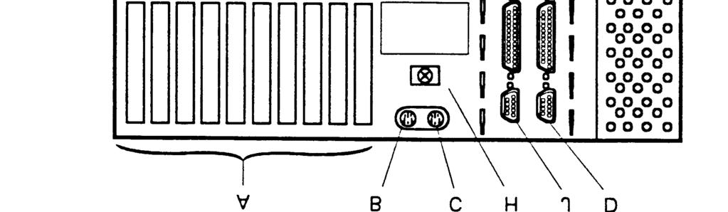
140 3 OM
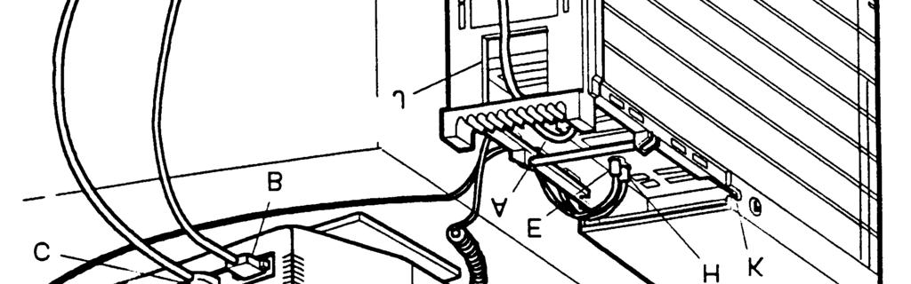
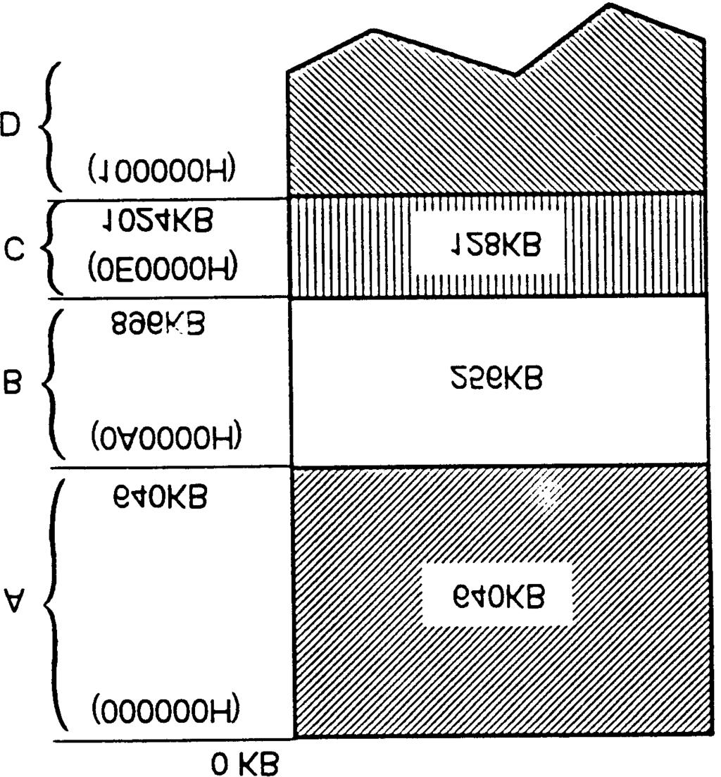
141 4 OM OM-00230

142 6 OM OM
143 8 OM
144 9 OM
145 10 OM
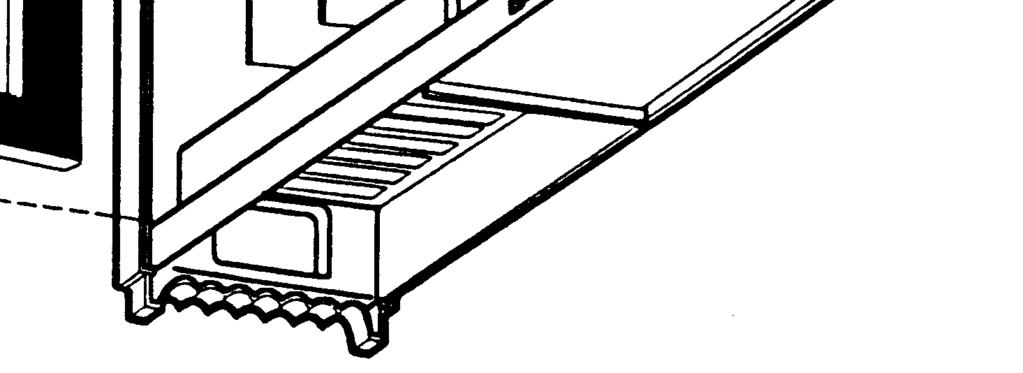
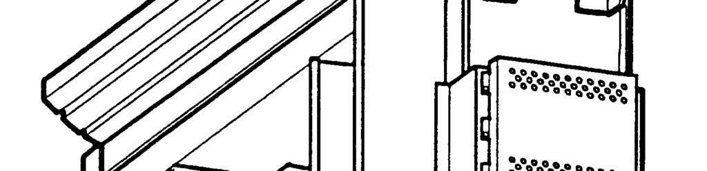

146 11 OM OM
147 13 OM OM-00418
148 15 OM OM-00109


149 17 OM

150 18 OM OM
151 20 OM
152 21 OM OM
153 23 OM OM-00123

154 25 OM

155 28 OM OM


156 30 OM-00384

157 31 OM OM


158 33 OM OM
159 35 OM OM
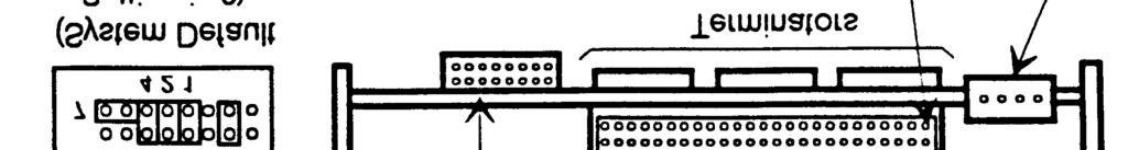

160 37 OM OM
161 39 OM-00128


162 40 OM OM-00437

163 42 OM OM-00439

164 44 OM OM-00108
165 46 OM OM
166 48 OM
167 49 OM-00314
168 50 OM
169 51 OM

170 52 OM
EISA Series Desktop. Computer Specifications. Processor Board. Main System Board. Mass Storage Bays. EISA configuration.
 diskette release diskette release E latch button \ I I option slots Five 32-bit EISA expansion slots (l6-bit and 8-bit ISA compatible); bus-mastering option cards allowable in all slots Internal; operation
Phoenix Technologies, Ltd.
 Phoenix Technologies, Ltd. AwardBIOS Version 4.51PG Post Codes & Error Messages Table of Contents POST Codes - 2 Error Messages - 7 ----------------------------------------------- Proprietary Notice and
Computer Specifications. Controllers. Interfaces. CPU and Memory. Epson EL 486UC. Diskette
 button I h&disk @ ===hw 7 \ AC inlet AC outlet monitor cable hard disk or diskette drive bay Icg / 1 Computer Specifications CPU and Memory 32-bit CPU System speed COM1 COM2 Parallel Intel 80486SX/25 microprocessor;
Troubleshooting. Resetting the System. Problems Following Initial System Installation. First Steps Checklist CHAPTER
 CHAPTER 6 This chapter helps you identify and solve problems that might occur while you are using the Cisco CDE110. If you are unable to resolve your server problems on your own, contact Cisco Technical
32-bit CPU Green PC energy saver POWER. button. Memory \ VGA ROM. Video RAM. Cache. Math coprocessor. PCI Chipset. voltage selector switch
 hard disk SPEED light POWER light access light RESET (HDD) drive bays button Computer Specifications / voltage switch RESE button option slots AC outlet I diskette drive POWER button / serial 1 Gal2 printer
S Series BIOS BIOS SETUP UTILITY. Entering the BIOS Setup Utility. Entering the Setup Utility After a Configuration Change or System Failure
 BIOS SECTION S6130 LifeBook S Series Notebook BIOS S Series BIOS BIOS SETUP UTILITY The BIOS Setup Utility is a program that sets up the operating environment for your notebook. Your BIOS is set at the
Keep the work area free of clutter and clean. Food and drinks are not allowed in the work area.
 29 Chapter 3 Computer Assembly Introduction This chapter addresses the process of the computer assembly process. The ability to successfully assemble a computer is a milestone for the PC Ttechnician. It
T Series BIOS BIOS SETUP UTILITY
 BIOS SECTION T4010 LifeBook T Series Tablet PC T Series BIOS BIOS SETUP UTILITY The BIOS Setup Utility is a program that sets up the operating environment for your tablet. Your BIOS is set at the factory
Troubleshooting & Repair
 Chapter Troubleshooting & Repair 6.1 Introduction This chapter provides the most common problem encountered with the M785 notebook computer and some troubleshooting means. Some of the common problems are:
User s Manual. MMX Enhanced MediaGX System Board. MMX Enhanced MediaGX System Board
 MMX Enhanced MediaGX System Board MMX Enhanced MediaGX System Board Trademarks and / or Registered trademarks are the properties of their respective owners. User s Manual IBM, PC/AT and PC/XT are trademarks
Fujitsu LifeBook T Series
 Fujitsu LifeBook T Series BIOS Guide LifeBook T Series Model: T3010/T3010D Document Date: 09/16/03 Document Part Number: FPC58-0992-01 FUJITSU PC CORPORATION 1 LifeBook T Series Tablet PC T Series BIOS
DECpc 400 MT/MTE Series Service Guide
 System Description 1 of 2 DECpc 400 MT System Board CPU Intel 80486 DECpc 400 MTE System Board CPU Intel 80486 Clock Speed ROM BIOS 33 MHz DX, 50 MHz DX2, 66 MHz DX2 128 KB Clock Speed ROM BIOS 33 MHz
Experiment #0. PC Hardware and Operating Systems
 Experiment #0 PC Hardware and Operating Systems Objective: The objective of this experiment is to introduce the operating systems and different hardware components of a microcomputer. Equipment: Microcomputer
Product Support Bulletin
 EPSON Product Support Bulletin Subject: Proper Method for Running Benchmark and Diagnostics Programs Date: 06/04/93 PSB No: S-0158 Page(s): 1 of 1 Originator: MWT This bulletin describes the proper method
Fujitsu LifeBook E Series
 Fujitsu LifeBook E Series BIOS Guide LifeBook E Series Models: E2010 Document Date: 02/05/03 Document Part Number: FPC58-0881-01 F U J I T S U P C C O R P O R A T I O N 1 LifeBook E Series BIOS E Series
Fujitsu LifeBook S Series
 Fujitsu LifeBook S Series BIOS Guide LifeBook S Series Model: S2020 Document Date: 10/30/03 Document Part Number: FPC58-1035-01 FUJITSU COMPUTER SYSTEMS 1 LifeBook S Series Notebook BIOS S Series BIOS
BIOS SECTION S6210/6220
 BIOS SECTION S6210/6220 LifeBook S Series Notebook BIOS S Series BIOS BIOS SETUP UTILITY The BIOS Setup Utility is a program that sets up the operating environment for your notebook. Your BIOS is set at
PCS42. i MHz i MHz i MHz internal (25 MHz system) i MHz internal (33 MHz system) 25 MHz or 33 MHz
 i MHz internal (33 MHz system) 25 MHz or 33 MHz") PCS42 CHARACTERISTICS Microprocessor Clock Architecture i486 SX @ 25 MHz i486 SX @ MHz i486 DX @ MHz i486 DX2 @ 50 MHz internal (25 MHz system) i486 DX2 @ 66 MHz internal ( MHz system) 25 MHz or MHz ISA
PCS42 CHARACTERISTICS Microprocessor Clock Architecture i486 SX @ 25 MHz i486 SX @ MHz i486 DX @ MHz i486 DX2 @ 50 MHz internal (25 MHz system) i486 DX2 @ 66 MHz internal ( MHz system) 25 MHz or MHz ISA
S Series BIOS BIOS SETUP UTILITY
 BIOS SECTION S2110 LifeBook S Series Notebook BIOS S Series BIOS BIOS SETUP UTILITY The BIOS Setup Utility is a program that sets up the operating environment for your notebook. Your BIOS is set at the
MMX Enhanced. 586 GXM-AV Main Board. Trademarks and / or Registered trademarks are the properties of their respective owners.
 586 GXM-AV Main Board Trademarks and / or Registered trademarks are the properties of their respective owners. User s Manual Version 1.1 The Information presented in this publication has been carefully
IBM Netfinity Servers
 IBM Netfinity Servers S10L-9798-01 IBM Netfinity 3000 - Type 8476 Models 10U, 10X, 11U, 11X, 15U, 15X, 16U, 16X, 20U, 20X, 21U, 21X, 30U, 30X, 31U, 31X, 40U, 40X 41U, 41X Hardware Maintenance Manual September
The PowerEdge 6450 systems offer the following major features:
 The Dell PowerEdge 6450 system, which supports up to four Intel Pentium III Xeon microprocessors (and future generation Intel microprocessors), is a featurerich, enterprise class server that offers the
This section describes how to install the following options: #!! #!% *+! Use Figure 8-1 to locate the system board features.
 This section describes how to install the following options: Expansion cards Memory upgrades Microprocessor upgrades This section also includes instructions for replacing the system battery, if necessary.!"
Troubleshooting the System Hardware
 CHAPTER 5 This chapter provides basic troubleshooting information to help you identify some common problems that might occur with your Wide Area Virtualization Engine (WAVE). This chapter contains the
Copyright IBM Corp FRONT - 1
 FRONT PICTURE 1 February 25, 1992 Part Number 10G6002 Form Number S04G-3295-01 FRONT - 1 Notices NOTICES Notices +--- Note! ----------------------------------------------------------+ Before using this
S Series BIOS BIOS SETUP UTILITY. Entering the BIOS Setup Utility. Entering the Setup Utility After a Configuration Change or System Failure
 BIOS SECTION S7010 LifeBook S Series Notebook BIOS S Series BIOS BIOS SETUP UTILITY The BIOS Setup Utility is a program that sets up the operating environment for your notebook. Your BIOS is set at the
DVD :50 PM Page 1 BIOS
 99 0789729741 DVD 3.07 06 09 2003 1:50 PM Page 1 BIOS 99 0789729741 DVD 3.07 06 09 2003 1:50 PM Page 2 2 BIOS AMI BIOS POST Checkpoint Codes Table 1 AMI BIOS POST Checkpoint Codes for All AMI BIOS Products
Computer Specifications
 power (speed) light hard disk access light power - button Controllers Video Diskette Hard disk nterfaces External VESA local bus video cam supports high resolution displays (preinstailed on systems sold
E Series BIOS BIOS SETUP UTILITY. Entering the BIOS Setup Utility. Entering the Setup Utility After a Configuration Change or System Failure
 BIOS SECTION E8020 LifeBook E Series BIOS E Series BIOS BIOS SETUP UTILITY The BIOS Setup Utility is a program that sets up the operating environment for your notebook. Your BIOS is set at the factory
Product Support Bulletin
 EPSON Product Support Bulletin Subject: Proper Method for Running Benchmark and Diagnostics Programs Date: 06/04/93 PSB No: S-0158 Page(s): 1 of 1 Originator: MWT This bulletin describes the proper method
SYSTEM SOFTWARE CONFIGURATION (SETUP UTILITY)
") SYSTEM SOFTWARE CONFIGURATION (SETUP UTILITY) The software configuration utilities allow certain Personal Computer operating parameters to be set. These utilities are supplied with the individual systems,
SYSTEM SOFTWARE CONFIGURATION (SETUP UTILITY) The software configuration utilities allow certain Personal Computer operating parameters to be set. These utilities are supplied with the individual systems,
Fujitsu Stylistic ST6000 Series
 Fujitsu Stylistic ST6000 Series BIOS Guide Stylistic Series Model: ST6012 Document Date: 12/01/2008 Document Part Number: FPC65-4369-01 FUJITSU COMPUTER SYSTEMS CORPORATION 1 Stylistic ST Series BIOS ST
M54E2 PCI/EISA Dual Pentium Processor System Board Manual
 M54E2 PCI/EISA Dual Pentium Processor System Board Manual. M54E2 PCI/EISA Dual Pentium Processor System Board Manual Document Number: 06-00210-06, Rev. 2C June 1996 221 Warren Ave., Fremont, CA 94539-7085
Introduction to Configuration. Chapter 4
 Introduction to Configuration Chapter 4 This presentation covers: > Qualities of a Good Technician > Configuration Overview > Motherboard Battery > Hardware Configuration Overview > Troubleshooting Configurations
M CHARACTERISTICS MOTHERBOARD 3 MB
 M300-04 CHARACTERISTICS Microprocessor Clock Architecture Memory Memory access Coprocessor Floppy Disk Hard Disk Streaming Tape Slots Video adapter HDU and FDU controller INTEL 386SX 0 MHz XT/AT with 3-bit
This chapter tells how to configure the system by setting the BIOS parameters. 3.1 Entering the AMI BIOS Setup
 Chapter 3 AMI BIOS This chapter tells how to configure the system by setting the BIOS parameters. 3.1 Entering the AMI BIOS Setup To enter the AMI BIOS Setup, press appears as shown below.. The AMI BIOS
Fujitsu LifeBook T Series
 Fujitsu LifeBook T Series BIOS Guide LifeBook T Series Model: T4020/T4020D Document Date: 08/08/2005 Document Part Number: FPC58-1407-01 FUJITSU COMPUTER SYSTEMS 1 LifeBook T Series Tablet PC T Series
System CMOS/BIOS Configuration PC Diagnostics
 System CMOS/BIOS Configuration PC Diagnostics (POST; Error Messages and Error Codes) CMOS/BIOS Complementary Metal Oxide Substrate (CMOS) A part of the motherboard that maintains system variables in static
Fujitsu LifeBook P Series
 Fujitsu LifeBook P Series BIOS Guide LifeBook P Series Model: P1120 Document Date: 10/30/02 Document Part Number: FPC58-0796-01 FUJITSU PC CORPORATION LifeBook P Series Notebook BIOS P Series BIOS BIOS
BIOS. Chapter The McGraw-Hill Companies, Inc. All rights reserved. Mike Meyers CompTIA A+ Guide to Managing and Troubleshooting PCs
 BIOS Chapter 8 Overview In this chapter, you will learn how to Explain the function of BIOS Distinguish among various CMOS setup utility options Describe option ROM and device drivers Troubleshoot the
Computers Are Your Future
 Computers Are Your Future 2008 Prentice-Hall, Inc. Computers Are Your Future Chapter 6 Inside the System Unit 2008 Prentice-Hall, Inc. Slide 2 What You Will Learn... Understand how computers represent
Product Support Bulletin
 EPSON AMERICA, INC. EPSON Product Support Bulletin Subject: EL 4S/33+ and EL 486UC+ OS/2 2.0 and 2.1 Display Drivers Date: 04/06/94 Page(s): 1 of 2 PSB No: S-0173 Originator: JAM This bulletin announces
Computer Specifications
 hard disk diskette diskette drive power drive release access light light access light button power supply fan AC output socket \ voltage selector switch expansion card slots blank filer panels /c AC input
Technical Specifications: Dell OptiPlex GX150 System
 Technical Specifications: Dell OptiPlex GX150 System Processor Microprocessor type Internal cache Intel Pentium III or Celeron microprocessor 32-kilobyte (KB) first-level (16-KB data cache; 16-KB instruction
Product Support Bulletin
 EPSON AMERICA, INC. EPSON Product Support Bulletin SUBJECT: MS Windows 3.x Stylus 400/800+/Color Printer Driver problems using the ActionPC/Tower-2000 Computers Date: 11/5/94 PSB No: PSB S-0179 Page(s):
Computer Maintenance. PC Disassembly and Reassembly. Copyright Texas Education Agency, All rights reserved.
 Computer Maintenance PC Disassembly and Reassembly 1 Enabling Objectives Computer Chassis (Cases) Power Supplies Configuring the Motherboard Configuring the Connectors CPU Interfaces RAM Installing a Hard
Manual: Errata 1 P R E L I M I N A R Y. Manual Index: 07. CP605 Manual: 25095
 CP605 Errata 1 Manual Index: 07 Table of Contents: 1. Reference: Page 5-3, Chapter 5, Phoenix BIOS... 1-3 ID 25095, Rev. 07 Errata 1-1 CP605 This page has been intentionally left blank. Errata 1-2 ID 25095,
Introduction to the Personal Computer
 Introduction to the Personal Computer 2.1 Describe a computer system A computer system consists of hardware and software components. Hardware is the physical equipment such as the case, storage drives,
Boot Sequence OBJECTIVES RESOURCES DISCUSSION PROCEDURE LAB PROCEDURE 2
 LAB PROCEDURE 2 Boot Sequence OBJECTIVES 1. Show the boot sequence of Marcraft 8000 Trainer. 2. See the extended memory count. 3. Change settings in CMOS. 4. See the LED sequence. 5. Detect hard disk drives.
Computer Specifications EPSON PROGRESSION. CPU and Memory. 10/19/92 Epson Progression-l
 power inlet diskette diskette release release button power latch. I button optional drive bay RESET button option card slots cove lock serial port Poe Computer Specifications CPU and Memory CPU (on card)
PC BIOS Settings: (22 Jan 2004) These settings will be required for either O.S. Installation or to improve the PC performance.
 These settings will be required for either O.S. Installation or to improve the PC performance.") PC BIOS Settings: (22 Jan 2004) These settings will be required for either O.S. Installation or to improve the PC performance. S.No. Standard Hard Disks Operation Reason 1. CMOS SETUP Keep Type setting
PC BIOS Settings: (22 Jan 2004) These settings will be required for either O.S. Installation or to improve the PC performance. S.No. Standard Hard Disks Operation Reason 1. CMOS SETUP Keep Type setting
A+ Guide to Hardware: Managing, Maintaining, and Troubleshooting, 5e. Chapter 1 Introducing Hardware
 : Managing, Maintaining, and Troubleshooting, 5e Chapter 1 Introducing Hardware Objectives Learn that a computer requires both hardware and software to work Learn about the many different hardware components
S Series BIOS BIOS SETUP UTILITY
 BIOS SECTION S7020 LifeBook S Series Notebook BIOS S Series BIOS BIOS SETUP UTILITY The BIOS Setup Utility is a program that sets up the operating environment for your notebook. Your BIOS is set at the
Review Questions on Computer Basics
 Review Questions on Computer Basics 1. Distinguish between and define (see glossary in Maxfield and Brown s Bebop Bytes Back for the definition of terms not found in Andrews A Guide to Managing and Maintaining
1993 Specifications CSJ SPECIAL SPECIFICATION ITEM Transportation Management Console
 1993 Specifications CSJ 0598-01-057 1.0 Description SPECIAL SPECIFICATION ITEM 6398 Transportation Management Console This Item shall govern for the furnishing and installation of Transportation Management
Computer Specifications. EPSON ActionNote 700 Series. Controllers. CPU and Memory. Interfaces. EPSON ActionNote 700 Series-l 4/94
 trackball hard disk drive Computer Specifications CPU and Memory CPU System speed Memory ROM Cyrix 32-bit, 3.3 volt Cx486DX-V33 microprocessor; includes built-in math coprocessor, 8KB of internal cache,
286 HT SINGLE CHIP SYSTEM BOARD USER'S MANUAL
 286 HT SINGLE CHIP SYSTEM BOARD USER'S MANUAL Table of Contents CHAPTER 1... 1 1-1 Features... 1 CHAPTER 2... 2 2-1 Layout... 2 2-2 Jumper Setting... 3 CHAPTER 3... 4 3-1 Memory Configuration... 4 CHAPTER
M4Pe PCI/EISA System Board Manual
 M4Pe PCI/EISA System Board Manual Document Number: 06-00218-02, Ver. 2A August 1994 221 Warren Ave., Fremont, CA 94539-7085 Copyright Notices Micronics Computers, Inc. The information contained in the
16MB Sound Flash Installation Instructions for E6400 Ultra, E4XT Ultra & E-Synth Ultra
 16MB Installation Instructions for E6400 Ultra, E4XT Ultra & E-Synth Ultra 6876 Use these instructions to install of rewriteable Flash Sound Memory to the E6400 Ultra, E4XT Ultra or the E-Synth Ultra.
Installation Guide AHA-1540CP/1542CP. ISA-to-SCSI Plug and Play High-Performance Bus Master Host Adapter with SCSISelect Utility
 R Installation Guide AHA-1540CP/1542CP ISA-to-SCSI Plug and Play High-Performance Bus Master Host Adapter with SCSISelect Utility 1 Introduction This Installation Guide explains how to install and configure
Copyright IBM Corp. 1991, 1992 FRONT - 1
 FRONT PICTURE 1 IBM PS/2 Models 35SX and 35LS Hardware Maintenance Reference March 17, 1992 Part Number 10G6620 Form Number S84F-9845-02 FRONT - 1 EDITION Edition Notice Safety Information Edition Notice
Fujitsu LifeBook A Series
 Fujitsu LifeBook A Series BIOS Guide LifeBook A Series Models: A3040 Document Date: 2/10/06 Document Part Number: FPC58-1482-01 F U J I T S U C O M P U T E R S Y S T E M S 1 LifeBook A Series Notebook
Fujitsu LifeBook A Series
 Fujitsu LifeBook A Series BIOS Guide LifeBook A Series Model: A6030 Document Date: 06/06/2007 Document Part Number: FPC58-1698-01 FUJITSU COMPUTER SYSTEMS CORPORATION 1 LifeBook A Series BIOS A Series
Fujitsu LifeBook T Series
 Fujitsu LifeBook T Series BIOS Guide LifeBook T Series Model: T1010 with UMTS Document Date: 01/15/2009 Document Part Number: FPC58-2038-01 FUJITSU COMPUTER SYSTEMS CORPORATION 1 LifeBook T Series BIOS
Fujitsu LifeBook P Series
 Fujitsu LifeBook P Series BIOS Guide LifeBook P Series Model: P7120/P7120D Document Date: 11/3/2005 Document Part Number: FPC58-1425-01 FUJITSU COMPUTER SYSTEMS CORPORATION LifeBook P7000 Notebook BIOS
Fujitsu LifeBook C Series
 Fujitsu LifeBook C Series BIOS Guide LifeBook C Series Model: C1320D Document Date: 09/06/2005 Document Part Number: FPC58-1401-01 FUJITSU COMPUTER SYSTEMS LifeBook C Series Notebook BIOS C Series BIOS
Fujitsu LifeBook N Series
 Fujitsu LifeBook N Series BIOS Guide LifeBook N Series Models: N6000 Document Date: 11/11/04 Document Part Number: FPC58-1268-01 F U J I T S U C O M P U T E R S Y S T E M S 1 LifeBook N Series Notebook
Fujitsu LifeBook P Series
 Fujitsu LifeBook P Series BIOS Guide LifeBook P Series Model: P-1032 P-1035 Document Date: 02/01/02 Document Part Number: FPC58-0653-01 FUJITSU PC CORPORATION LifeBook P Series BIOS P Series BIOS BIOS
TABLE OF CONTENTS 1. INTRODUCTION 2. SPECIFICATION 3. HARDWARE INSTALLATION 6EX 1.1. PREFACE KEY FEATURES PERFORMANCE LIST...
 6EX TABLE OF CONTENTS 1. INTRODUCTION 1.1. PREFACE...1-1 1.2. KEY FEATURES...1-1 1.3. PERFORMANCE LIST...1-2 1.4. BLOCK DIAGRAM...1-3 1.5. INTRODUCE THE Pentium II Processor & AGP...1-4 1.6 What is AGP?...
EXP8049. User s Manual TABLE OF CONTENTS
 EXP8049 User s Manual TABLE OF CONTENTS CHAPTER INTRODUCTION.... OVERVIEW....2 SYSTEM FEATURES....3 SYSTEM SPECIFICATION... 2.4 SYSTEM PERFORMANCE... 2.5 EXP8049 BOARD LAYOUT... 3 CHAPTER 2 INSTALLATION...4
Product Support Bulletin
 Product Support Bulletin Subject: Equity LT - 286e Questions and Answers Date: 9/25/89 Page: 1 of 7 PSB No: Originator: General Q1. Q2. Q3. What microprocessor does the Equity LT-286e use? The Equity LT
Fujitsu STYLISTIC Q Series
 Fujitsu STYLISTIC Q Series BIOS Guide STYLISTIC Q Series Model: Q552 Document Date: 5252012 Document Part Number: FPC58-3061-01 FUJITSU AMERICA, INC. 1 STYLISTIC Q552 BIOS Q Series BIOS BIOS SETUP UTILITY
Macintosh SE/30. Overview
 Overview The Macintosh SE/30 personal computer was designed for people who want maximum performance from a compact computer system. It provides up to four times the computational speed of the Macintosh
AHA-1540C/1542C Installation Guide
 AHA-1540C/1542C Installation Guide 1 Getting Started This guide provides the steps required for basic installation of the AHA-1540C and AHA-1542C ISAto-SCSI Host Adapters. Procedures are the same for both
TABLE OF CONTENTS 1. INTRODUCTION 2. SPECIFICATION 3. HARDWARE INSTALLATION 6BA
 6BA TABLE OF CONTENTS 1. INTRODUCTION 1.1. PREFACE...1-1 1.2. KEY FEATURES...1-1 1.3. PERFORMANCE LIST...1-2 1.4. BLOCK DIAGRAM...1-3 1.5. INTRODUCE THE Pentium II / III Processor...1-4 1.6. What is AGP?...1-5
BIOS UPDATES Click to scan for Bios Updates
 Phoenix BIOS Beep - BIOS Central 1 di 16 13/02/2012 19:45 Home Forums About Us Awards Contact Us Upgrade your BIOS BIOS UPDATES Click to scan for Bios Updates BIOS Post: Acer BIOS Post ALR BIOS Post AMIT/AMI
Fujitsu LifeBook N Series
 Fujitsu LifeBook N Series BIOS Guide LifeBook N Series Models: N6400 Document Date: 07/16/2007 Document Part Number: FPC58-1702-01 FUJITSU COMPUTER SYSTEMS CORPORATION 1 LifeBook N Series BIOS N Series
N Series BIOS BIOS SETUP UTILITY
 BIOS SECTION N3530 LifeBook N Series Notebook BIOS N Series BIOS BIOS SETUP UTILITY The BIOS Setup Utility is a program that sets up the operating environment for your notebook. Your BIOS is set at the
How Hardware and Software Work Together
 C3_CH0_39 CHAPTER How Hardware and Software Work Together C In this chapter, you will learn: omputer systems contain both hardware and How an operating system manages software, and computer technicians
1. S Series BIOS BIOS SETUP UTILITY
 BIOS SECTION S6010 1. S Series BIOS BIOS SETUP UTILITY The BIOS Setup Utility is a program that sets up the operating environment for your notebook. Your BIOS is set at the factory for normal operating
TABLE OF CONTENTS 1. INTRODUCTION 2. SPECIFICATION 3. HARDWARE INSTALLATION 6EM 1.1. PREFACE KEY FEATURES PERFORMANCE LIST...
 6EM TABLE OF CONTENTS 1. INTRODUCTION 1.1. PREFACE...1-1 1.2. KEY FEATURES...1-1 1.3. PERFORMANCE LIST...1-2 1.4. BLOCK DIAGRAM...1-3 1.5. INTRODUCE THE Pentium II Processor & AGP...1-4 1.6 What is AGP?...1-6
Fujitsu LifeBook A & V Series
 Fujitsu LifeBook A & V Series BIOS Guide LifeBook A & V Series Models: A1110/A1120 V1030 Document Date: 10/01/2008 Document Part Number: FPC65-4363-01 FUJITSU COMPUTER SYSTEMS CORPORATION 1 LifeBook A1110/V1030
A Series BIOS BIOS SETUP UTILITY
 BIOS SECTION A3110 LifeBook A Series BIOS A Series BIOS BIOS SETUP UTILITY The is a program that sets up the operating environment for your notebook. Your BIOS is set at the factory for normal operating
Table of Contents. Introduction 2 1. Intelligent Remote Control 2 2. Charging the Remote Control 3
 Table of Contents Introduction 2 1. Intelligent Remote Control 2 2. Charging the Remote Control 3 Getting Started 6 1. Activating the Remote Control 6 2. Selecting a Device 7 3. Operating a Device 8 4.
ROM. Video RAM Shadow RAM. Numeric coprocessor. Diskette drive. Hard disk. Parallel Serial (2) LCD and CRT. Speaker. Modem Phone jack.
 LCD and CRT. Speaker. Modem Phone jack.") Computer Specifications Main Unit CPU System speed Memory 486SLC microprocessor Turbo and Normal speeds available; Turbo speed depends on CPU (25 MHz or 33 MHz), Normal speed is simulated 8 MHz speed;
Computer Specifications Main Unit CPU System speed Memory 486SLC microprocessor Turbo and Normal speeds available; Turbo speed depends on CPU (25 MHz or 33 MHz), Normal speed is simulated 8 MHz speed;
About the Presentations
 About the Presentations The presentations cover the objectives found in the opening of each chapter. All chapter objectives are listed in the beginning of each presentation. You may customize the presentations
CLK. Slot1 VIA ATX Mainboard. User s Manual 4
 2.1. Mainboard Layout Drawing CLK AGP 1 H14.318 Slot1 VIA693-133 ATX Mainboard ISA2 ISA1 User s Manual 4 2.2. Hardware Installation Steps 2.2.1. Installing System Memory The mainboard is equipped with
Computer Assembly Step by Step DRAFT
 9781587132636_ch03.qxp 8/20/10 1:37 PM Page 79 CHAPTER 3 Computer Assembly Step by Step Objectives Upon completion of this chapter, you should be able to answer the following questions: How do I open the
Fujitsu LifeBook U Series
 Fujitsu LifeBook U Series BIOS Guide LifeBook U Series Model: UH900 Document Date: 01/07/2010 Document Part Number: FPC58-2547-01 FUJITSU AMERICA, INC. 1 LifeBook U Series BIOS U Series BIOS BIOS SETUP
KVM08KD. KVM Switch with Keyboard Mouse Build In
 KVM08KD KVM Switch with Keyboard Mouse Build In COPYRIGHT This document is a copyright of the original manufacturer, 2000. The original manufacturer reserves the right to make improvements to the product(s)
Cisco MCS-78XX Boot Error Codes
 Page 1 of 13 Cisco MCS-78XX Boot Error Codes TAC Notice: What's Changing on TAC Web Contents Introduction Prerequisites Requirements Components Used Conventions POST POST Error Message NetPro Discussion
PhoenixBIOS 4.0 Revision 6
 Phoenix Technologies Ltd. PhoenixBIOS 4.0 Revision 6 User's Manual Phoenix Technologies Ltd., 411 E. Plumeria, San Jose, CA 95134 Copyright Disclaimer Purpose of Document PhoenixBIOS 4.0 User's Manual
Fujitsu LifeBook A Series
 Fujitsu LifeBook A Series BIOS Guide LifeBook A Series Model: A1010 Document Date: 05/20/02 Document Part Number: FPC58-0681-01 FUJITSU PC CORPORATION 1 LifeBook A Series Notebook BIOS A Series BIOS SYSTEM
Chapter 3: Computer Assembly
 Chapter 3: Computer Assembly IT Essentials v6.0 ITE v6.0 1 Chapter 3 - Sections & Objectives 3.1 Assemble the Computer Build a Computer. 3.2 Boot the Computer Explain how to verify BIOS and UEFI settings.
Pharmacy college.. Assist.Prof. Dr. Abdullah A. Abdullah
 The kinds of memory:- 1. RAM(Random Access Memory):- The main memory in the computer, it s the location where data and programs are stored (temporally). RAM is volatile means that the data is only there
Fujitsu LifeBook A Series
 Fujitsu LifeBook A Series BIOS Guide LifeBook A Series Model: A3130 Document Date: 06/20/2007 Document Part Number: FPC58-1706-01 FUJITSU COMPUTER SYSTEMS CORPORATION 1 LifeBook A Series BIOS A Series
machine cycle, the CPU: (a) Fetches an instruction, (b) Decodes the instruction, (c) Executes the instruction, and (d) Stores the result.
 Fetches an instruction, (b) Decodes the instruction, (c) Executes the instruction, and (d) Stores the result.") Central Processing Unit (CPU) A processor is also called the CPU, and it works hand in hand with other circuits known as main memory to carry out processing. The CPU is the "brain" of the computer; it
Central Processing Unit (CPU) A processor is also called the CPU, and it works hand in hand with other circuits known as main memory to carry out processing. The CPU is the "brain" of the computer; it
Providing Fundamental ICT Skills for Syrian Refugees PFISR
 Yarmouk University Providing Fundamental ICT Skills for Syrian Refugees (PFISR) Providing Fundamental ICT Skills for Syrian Refugees PFISR Dr. Amin Jarrah Amin.jarrah@yu.edu.jo Objectives Covered 1.1 Given
1 Interference from generator and lighting that could result in unclean power is known as. 3 Form factor of motherboard define its
 1 IT ESS Class Test 1 1 Interference from generator and lighting that could result in unclean power is known as. Blackout Brownout Noise Spike 2 CPU speed is measure in. cycles per second click per second
BIOS Setup DESKPOWER 5000
 BIOS Setup DESKPOWER 5000 1 Preface What is BIOS setup? BIOS setup is a program that helps the user set up a hardware environment, including memory, hard disks, and floppy disk drives. Minimum setup has