ArdPicProg. Arduino PIC Programmer Construction Manual. Version 1.2 Release date 03/2015. Gregor Schlechtriem
|
|
|
- Brandon Reed
- 6 years ago
- Views:
Transcription

1 ArdPicProg Arduino PIC Programmer Construction Manual Version 1.2 Release date 03/2015 Gregor Schlechtriem
2 Table of Contents Helpful Hints 3 Contents of the Kit and Tools needed 5 Construction 7 Step 1: Equipping of Resistors R1, R2 and R5 R Step 2: Equipping of the Capacitor C Step 3: Equipment of the Reset Button... 9 Step 4: Equipment of the LEDs... 9 Step 5: Equipment of JP8 (angled female connector) Step 6: Equipment of the transistors Q Step 7: Equipment of the DC-DC-converter Step 8: Equipment of the ZIF socket Step 9: Equipment of the RJ11 connector Step 10: Equipment of the headers (for connecting to the Arduino) Step 11: Solder joint Commissioning 17 ArdPicProg pinning 19 ArdPicProg schematics 21 ii
3 1 Helpful Hints Before you begin with the construction of your ArdPicProg, it is recommended that you first read these instructions completely. Then you will know what matters and will be able to avoid mistakes which will be hard to fix afterwards. A basic understanding of electronic parts and their handling, soldering and about the Arduino are required for the construction and the commissioning of the ArdPicProg. Conduct the soldering and the wiring in an orderly and conscientious manner; don t use acidic solder of any kind. Make sure that there are no cold solder joints. Keep these things in mind, because an unclean or bad joint, a defective contact or a bad construction cause a time-consuming search for faults and could possibly cause a destruction of the components. The possibility that something won t work after the assembly, can be drastically diminished by working conscientiously and orderly. Check every step before continuing. Follow the instructions! Only do the things written in the manual and do not skip any steps! Check every step twice: once for building and once to check. Please take the time it needs to build this kit. Tinkering is not task work and should be enjoyable! 3
4 Room for your notes: 4
5 2 Contents of the Kit and Tools needed The kit in front of you contains all the necessary components needed to build an ArdPicProg. Please verify the completeness with the help of the attached checklist. Checklist: ArdPicProgrammer Quantity Resistors* Description 1 10k, 0,25W R1 1 1k, 0,25W R2 2 4k7, 0,25W R5,R R, 0,25W R6 *R3 and R4 are not included. Capacitors 1 100n C1 Semiconductors 1 BC548 Q1 1 LED 3mm green LED1 1 LED 3mm red LED2 Other 2 Pin Header 6 pol. J3, ANALOG 2 Pin Header 8 pol. J1, POWER 1 RJ-12 Socket J7 1 Female Header 6 pol. gew. (2x3pol) J8 1 DC-DC-CONVERTER TME_0512S TME_0512S 5
6 Checklist: ArdPicProgrammer (continued) Quantity Description 1 RESET-Button RESET 1 ZIF socket pins ZX1 1 Circuit Board You also need the following tools: 1. Electronic Soldering Iron 2. Electronic Solder 3. Side cutters to shorten the component connections Additionally, to commission your programmer you will need: 1. Arduino with a programming sketch (Downloadable online) 2. Computer with application software (Downloadable online) 6
7 3 Construction In order to simplify construction this manual is split into two major parts: 1. Populating of the components on or under the circuit board 2. Commissioning and function test The following paragraphs will describe how to populate the components on the circuit board. First, all the components on the top of the circuit board will be equipped. The silk print on the circuit board will support this process The order of the placement of the components depends on their height; generally the lower pieces will be placed first. Afterwards, connect headers, which connect your programmer to your Arduino are placed on the underside of the circuit board and then soldered from above. Step 1: Equipping of Resistors R1, R2 and R5 R7 The resistors R1, R2 and R5 R7 will be equipped first. In order to do this, bend the connecting wires at a 90 angle based on the grid dimensions and then place them in the designated holes (refer to the enclosed graphics) Please pay close attention to the color coding of the resistors. To ensure that none of the parts of the circuit board fall off, bend the connecting wires at a roughly 45 angle apart and the solder them carefully with the conducting paths on the back of the circuit board. Afterwards cut off the excess wire. 7

8 Step 2: Equipping of the Capacitor C1 Now, the Capacitor C1 will be inserted followed by a mild angling of the connection wires in order to prevent the pieces falling out. In this case, we are working with a non-polarized ceramic capacitor, therefore the alignment is irrelevant 8

9 Step 3: Equipment of the Reset Button The following steps include the insertion and soldering of the Reset Button. The position of the hole only permits one mounting direction, which guarantees a correct alignment. Step 4: Equipment of the LEDs LEDs are polarized components. Therefore please pay close attention to the alignment when doing this step. The casing of the LED is flattened on one side (as indicated on the following image by the red arrow). Also, to support a correct placement, the LED pins feature a different length; the pin on the flattened side is shorter. Place the LEDs in the respective positions. The LEDs are placed directly on the pcb. After you put the LEDs into the board, flip it over and bend the leads outwards so they will stay in place while you solder them. After you solder the leads, clip them close to the board. 9


10 Step 5: Equipment of JP8 (angled female connector) The six pin female connector JP8 is comprised of two three pin connectors. Please make sure that both connectors are aligned properly in order to warrant a stable and reliable connection while operating the programmer. 10


11 Step 6: Equipment of the transistors Q1 A transistor is again a polarized component and you would have to make sure again that the placement of the transistor exactly matches the print on the circuit board. Step 7: Equipment of the DC-DC-converter In this step you would place and solder the DC-DC converter. Since this component is polarized again you have to make sure to position the converter correctly. 11
, then move the socket all the way to the left as shown in the following image meaning")
12 Step 8: Equipment of the ZIF socket Place the ZIF socket in the position indicated on the top of the circuit board. Once again, verify the positioning. If your kit s ZIF socket would feature less than 24 pins (which does not affect the programmer s feature set), then move the socket all the way to the left as shown in the following image meaning that the rightmost holes remain unused. To avoid the socket from falling out of ist position when turning the board slightly bend the two outer diagonal pins and then go ahead and solder all the other pins. Step 9: Equipment of the RJ11 connector The only remaining component equipped from the top side is the RJ11 connector. 12

13 Step 10: Equipment of the headers (for connecting to the Arduino) Finally the headers for connecting to the Arduino are equipped. Please refer to the following image: on the bottom side of the circuit board the two six pin connectors are placed and soldered, on the top side the two eight pin connectors are assembled. Please note the positioning by looking at the solder joints in the image additionally, free holes are marked with an X. To improve and simplify mechanical alignment you may plug the connectors into an Arduino (with no power attached). Then stack the programmer pcb on top and solder the pins. In this setup the Arduino acts as a mechanical template for the required alignment. However, some level of professional soldering is required to avoid exercising to much heat stress on you Arduino. 13

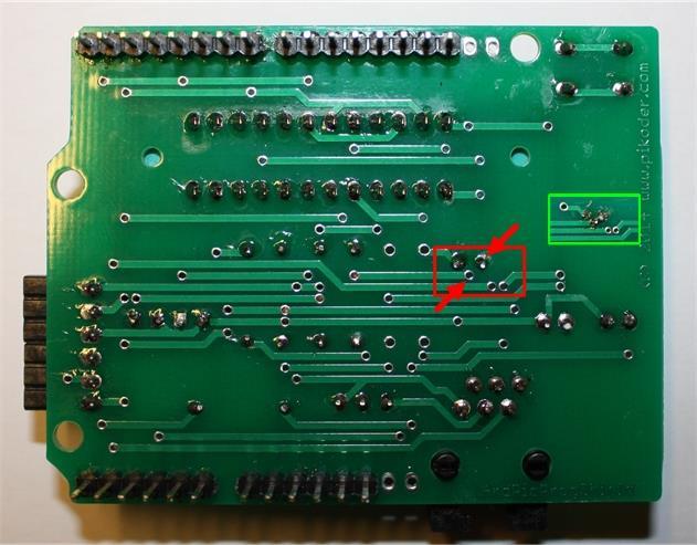
14 XX XX Step 11: Solder joint Unfortunately, on required connection is missing on the circuit board. Since the programmer requires this connection to fully function, you would have to place a solder joint on the circuit board. The following image indicates which points have to be connected (marked with red arrows). The connection itself can be created by adding some excess solder as shown in the image with the green frame. As an alternative you could use a short piece of wire. 14
15 15
16 Room for your notes: 16
17 4 Commissioning The commissioning of the programmer is described in the ArdPicProg User Guide. This document can be downloaded under User Guide.pdf. 17
18 Room for your notes: 18

19 A ArdPicProg pinning 19
20 Room for your notes: 20
21 B ArdPicProg schematics 21
Assembly Guide. LEDs. With these assembly instructions, you can easily build your own SWT16. All required components are included in this kit.
 Assembly Guide With these assembly instructions, you can easily build your own SWT16. All required components are included in this kit. You need the following tools: soldering iron, wire cutter and solder.
Post Tenebras Lab. Written By: Post Tenebras Lab
 Post Tenebras Lab PTL-ino is an Arduino comptaible board, made entirely out of through-hole components. It is a perfect project to learn how to solder and start getting into the world of micro controllers.
RC Tractor Guy Controller V2.1 Assembly Guide
 RC Tractor Guy Controller V. Assembly Guide Features 0 Push button inputs Dual axis thumb sticks with built-in push button Rotary encoders with built-in push button MCU Socket to suit Meduino Mega 560
Electronics Construction Manual
 Electronics Construction Manual MitchElectronics 2018 Version 1 07/05/2018 www.mitchelectronics.co.uk CONTENTS Introduction 3 How To Solder 4 Resistors 5 Capacitors 6 Diodes and LEDs 7 Switches 8 Transistors
[Note: Power adapter is not included in the kits. Users need to prepare a 9 12 V ( >300mA capacity ) DC power supply]
![[Note: Power adapter is not included in the kits. Users need to prepare a 9 12 V ( >300mA capacity ) DC power supply]](/thumbs/76/74094055.jpg "[Note: Power adapter is not included in the kits. Users need to prepare a 9 12 V ( >300mA capacity ) DC power supply]") 062 LCD Oscilloscope Assembly Notes Applicable Models: 06203KP, 06204KP DN062-18v02 Important Notes 1. Some components shown in the schematic and PCB layout are for options or adjustments. They do not
062 LCD Oscilloscope Assembly Notes Applicable Models: 06203KP, 06204KP DN062-18v02 Important Notes 1. Some components shown in the schematic and PCB layout are for options or adjustments. They do not
Installation/assembly manual for DCC/Power shield
 Installation/assembly manual for DCC/Power shield The DCC circuit consists of the following components: R1/R6 R2/R3 R4/R5 D1 C2 2 kω resistor ½ Watt (colour code Red/Black/Black/Brown/Brown) 10 kω resistor
Construction Construction Instructions
 Semi-Virtual Diskette SVD Construction Construction Instructions PCB version 2.0 September 2004 Eric J. Rothfus Table of Contents Table of Contents... i Parts List...1 Construction Overview...5 PCB Construction...
Electronics Construction Manual
 Electronics Construction Manual MitchElectronics 2019 Version 3 04/02/2019 www.mitchelectronics.co.uk CONTENTS Introduction 3 How To Solder 4 Resistors 5 Capacitors 6 Diodes and LEDs 7 Switches 8 Transistors
Storage Card Interface Kit
 Storage Card Interface Kit for MultiMediaCards(MMC) and Secure Digital Cards (SD) MMSD3K The MMSD3K is complete development kit interfaced to a SD or MMC card. This board ideal for projects that involve
Storage Card Interface Kit
 Storage Card Interface Kit for MultiMediaCards(MMC) and Secure Digital Cards (SD) MMSD3F The MMSD3K is complete development kit interfaced to a SD or MMC card. This board ideal for projects that involve
PARTS LIST 1 x PC Board 36 x 5mm Red LED 36 x 12mm LED Standoff 36 x NPN Transistor 36 x 10kΩ Resistor OTHER PARTS YOU MAY NEED
 PARTS LIST 1 x PC Board 36 x 5mm Red LED 36 x 12mm LED Standoff 36 x NPN Transistor 36 x 150Ω Resistor 36 x 10kΩ Resistor 17 x Mini Toggle on-off 8 x Mini Toggle (on)-off-(on) 1 x 470Ω Resistor 1 x 47µF
AVR-M Rev 5 ASSEMBLY
 AVR-M Rev 5 ASSEMBLY The AVR_M is a very compact self contained Atmel AVR mcu controller board. It includes an onboard serial programmer (via PC com port), an I2C eeprom and can use a Mega163, Mega16 or
dual bipolar voltage controlled step sequencer DIY ASSEMBLY MANUAL v1.03
 dual bipolar voltage controlled step sequencer DIY ASSEMBLY MANUAL v1.03 Contents Contents... 2 Introduction... 3 Part Sourcing Notes for Non Kit Builders... 3 Eurorack Kit Assembly... 4 Resistors and
Arduino shield kit. 1) Low Pass Filter (LPF) kit (available for LF/MF/HF/VHF bands 2,200m to 6m)
 Low Pass Filter (LPF) kit (available for LF/MF/HF/VHF bands 2,200m to 6m)") Arduino shield kit 1. Introduction The QRP Labs Arduino shield kit is a versatile shield that can be used for various purposes. Write your own Arduino sketch to define the functionality! For example: 1)
Arduino shield kit 1. Introduction The QRP Labs Arduino shield kit is a versatile shield that can be used for various purposes. Write your own Arduino sketch to define the functionality! For example: 1)
K8099 NIXIE CLOCK. * optional enclosure TKOK19 (black) - TKOK17 (white) ** optional plexiglass enlcosure B8099 ILLUSTRATED ASSEMBLY MANUAL
 - TKOK17 (white) ** optional plexiglass enlcosure B8099 ILLUSTRATED ASSEMBLY MANUAL") Total solder points: 230 + 74 Difficulty level: beginner 1 2 3 4 5 advanced NIXIE CLOCK K8099 ** * A unique combination of both vintage and modern electronics ILLUSTRATED ASSEMBLY MANUAL H8099IP-1 * optional
Total solder points: 230 + 74 Difficulty level: beginner 1 2 3 4 5 advanced NIXIE CLOCK K8099 ** * A unique combination of both vintage and modern electronics ILLUSTRATED ASSEMBLY MANUAL H8099IP-1 * optional
SM010, Assembly Manual PCB Version 1.0
 180 SM010, Assembly Manual MATRIXARCHATE 16 8 IO SEQUENTIAL MATRIX SIGNAL ROUTER SM010 1 2 1 2 3 4 5 3 4 5 6 7 8 9 10 11 12 6 7 8 9 10 11 12 13 14 15 16 PROGRAM A B C D E F G H f1 f2 20.000 180 SSSR Labs
15 Channel IR transmitter. Total solder points: 53 Difficulty level: beginner advanced K8049 ILLUSTRATED ASSEMBLY MANUAL
 15 Channel IR transmitter Compatible with most Velleman IR receiver kits, 4 adresses allow the use of multiple receivers in one room. Total solder points: 53 Difficulty level: beginner 1 2 3 4 5 advanced
The Basic Counter. Hobby Electronics Soldering Kit. Instruction Guide
 The Basic Counter Hobby Electronics Soldering Kit Instruction Guide TM For the best outcome, follow each step in order. We recommend reading this guide entirely before you get started. Tools required:
Tubbutec Sumtiple Kit Version Construction Manual
 Tubbutec Sumtiple Kit Version Construction Manual This document describes the construction of the Sumtiple Kit. The following parts are included: 1x Sumtiple PCB with SMD-Parts already soldered 1x Front
OpenSprinkler v2.1u Build Instructions
 OpenSprinkler v2.1u Build Instructions (Note: all images below are 'clickable', in order for you to see the full-resolution details. ) Part 0: Parts Check Part 1: Soldering Part 2: Testing Part 3: Enclosure
ARRL ETP Solder Hour Clock Kit Construction Manual
 ARRL ETP Solder 101 24-Hour Clock Kit Construction Manual Do a complete parts check cross checking the individual parts against the parts list. Pay particular attention to the color code for the resistors:
Building the FlipChip Tester
 Building the FlipChip Tester 1. Assembly of the Core Board You will need a fine low-wattage soldering iron and a Voltmeter. Take your time to solder the components on the Core Board. Better to spend a
SPIRIT. Phase 5 Analog Board Computer and Electronics Engineering
 SPIRIT Phase 5 Analog Board Computer and Electronics Engineering In this exercise you will assemble the analog controller board and interface it to your TekBot. Print out the schematic, silkscreen and
VG-305A AC Traffic Light Controller Kit
 Galak Electronics Electronic kits and components Website: GalakElectronics.com Email: sales@galakelectronics.com Phone: (302) 832-1978 VG-305A AC Traffic Light Controller Kit Thank you for your purchase
An open-source hardware+software project. For design files and additional documentation, please visit:
 An open-source hardware+software project. For design files and additional documentation, please visit: http://www.evilmadscientist.com/go/diavolino Support: http://www.evilmadscientist.com/forum/ Distributed
GLiPIC Ver C Assembly manual Ver 1.0
 GLiPIC Ver C Assembly manual Ver 1.0 Last Rev 1.1 Oct 30, 2001 Author: Ranjit Diol Disclaimer and Terms of Agreement As with any kit, only the individual parts supplied are guaranteed against defects and
Assembly Instructions (8/14/2014) Your kit should contain the following items. If you find a part missing, please contact NeoLoch for a replacement.
 Your kit should contain the following items. If you find a part missing, please contact NeoLoch for a replacement.") NeoLoch NLT-28P-LCD-5S Assembly Instructions (8/14/2014) Your kit should contain the following items. If you find a part missing, please contact NeoLoch for a replacement. Kit contents: 1 Printed circuit
NeoLoch NLT-28P-LCD-5S Assembly Instructions (8/14/2014) Your kit should contain the following items. If you find a part missing, please contact NeoLoch for a replacement. Kit contents: 1 Printed circuit
Morse Code Practice Oscillator
 Features Description Keyer speed range: Limited only by keying source True Sine wave tone output Tone Volume Control Tone Frequency Control Internal Speaker 1/8 External Speaker/Headphone Jack RCA Key
Universal Keying Adapter 3+
 Universal Keying Adapter 3+ The Universal Keying Adapter Version 3+ kit will allow you to key nearly any transmitter or transceiver with a straight key, electronic keyer, computer serial or parallel port
Ultimate LPF kit: Relay-switched LPF kit
 Ultimate LPF kit: Relay-switched LPF kit PCB Revision 4 1. Introduction Thank you for purchasing the QRP Labs relay-switched low-pass filter (LPF) kit. This kit is designed to complement the Ultimate3
Manual Main PCB Small-MIDI 4
 Index PARTLIST MAIN PCB... 2 INTRODUCTION... 3 GENERAL... 3 THE CIRCUIT... 3 ASSEMBLY KIT... 4 ASSEMBLY OF THE PCB... 4 An important tip...... 4 ASSEMBLY... 4 THE CONNECTORS... 4 Power supply J1... 4 IDC
UF-3701 Power Board Construction Guide
 Page 1/5 Soldering and Part Placement See the Chapter 3 of the MIT 6270 Manual for information on electronic assembly, including soldering techniques and component mounting. Construction Information All
Deep Vibes. Wobbly Optical Vibe action
 Deep Vibes Wobbly Optical Vibe action Contents of this document are 2018 Pedal Parts Ltd. No reproduction permitted without the express written permission of Pedal Parts Ltd. All rights reserved. Important
KAA Watt x 2 Class-D Audio Amplifier Kit
 KAA10021 50 Watt x 2 Class-D Audio Amplifier Kit This amplifier kit uses Texas Instruments TPA3116D2 stereo audio amplifier IC for driving speakers up to 50 watts @ 4 ohm per channel in stereo mode and
The Sudden Storm Kit. by QRPme. Builder s Guide. version4.2. for. Sudden Storm ][ Ver4 (red pcb) Updated 01/10/2012
![The Sudden Storm Kit. by QRPme. Builder s Guide. version4.2. for. Sudden Storm ][ Ver4 (red pcb) Updated 01/10/2012](/thumbs/75/72448638.jpg "The Sudden Storm Kit. by QRPme. Builder s Guide. version4.2. for. Sudden Storm ][ Ver4 (red pcb) Updated 01/10/2012") The Sudden Storm Kit by QRPme Builder s Guide version4.2 for Sudden Storm ][ Ver4 (red pcb) Updated 01/10/2012 Open the can and the adventure begins 1 Organize the parts and take an inventory Bill of Materials
The Sudden Storm Kit by QRPme Builder s Guide version4.2 for Sudden Storm ][ Ver4 (red pcb) Updated 01/10/2012 Open the can and the adventure begins 1 Organize the parts and take an inventory Bill of Materials
LED Sequencer 1.0 / 1.5
 LED Sequencer 1.0 / 1.5 Instruction Manual Eastern Voltage Research, LLC May 2012, Rev 2 1 http://www.easternvoltageresearch.com Introduction to the LED Sequencer 1.0 Thank you for purchasing the LED Sequencer
DELUXE STEREO AMPLIFIER KIT
 ESSENTIAL INFORMATION BUILD INSTRUCTIONS CHECKING YOUR PCB & FAULT-FINDING MECHANICAL DETAILS HOW THE KIT WORKS CREATE YOUR OWN SPEAKER DOCK WITH THIS DELUXE STEREO AMPLIFIER KIT Version 2.0 Build Instructions
Shack Clock kit. U3S Rev 2 PCB 1. Introduction
 Shack Clock kit U3S Rev 2 PCB 1. Introduction Thank you for purchasing the QRP Labs Shack Clock kit. This clock uses the Ultimate3S QRSS/WSPR kit hardware, but a different firmware version. It can be used
OpenSprinkler v2.2u Build Instructions
 OpenSprinkler v2.2u Build Instructions (Note: all images below are 'clickable', in order for you to see the full-resolution details. ) Part 0: Parts Check Part 1: Soldering Part 2: Testing Part 3: Enclosure
QUASAR KIT No DIGITAL DOWN TIMER 99 MIN WITH PIC
 QUASAR KIT No 1173 - DIGITAL DOWN TIMER 99 MIN WITH PIC KIT 1173 is a digital countdown timer based on a micro controller, thus securing reliability and excellent operation under any circumstances. It
E-Limitator (Kit) on to your game board or a suitable PC interface. General Advice for building a circuit
 on to your game board or a suitable PC interface. General Advice for building a circuit") E-Limitator (Kit) Digital joysticks are divided by the number of directions that can be controlled with them. The most common are 2-, 4- and 8-way. It's uncommon that a developer has already built in a
E-Limitator (Kit) Digital joysticks are divided by the number of directions that can be controlled with them. The most common are 2-, 4- and 8-way. It's uncommon that a developer has already built in a
TIME WIZARD MULTI CLOCK DIVIDER BUILDING GUIDE
 TIME WIZARD MULTI CLOCK DIVIDER BUILDING GUIDE Table of Contents 0. Components List + Tools 0. PCB Sides 03. PCB Assembly 04_. Diode N448 04_. Laying Resistors 04_3. Capacitors 04_4. Quartz 04_5. 78L05
DMX CONTROLLED RELAY K8072
 Total solder points: 167 Difficulty level: beginner 1 2 3 4 5 advanced DMX CONTROLLED RELAY K8072 f the means o ol. y b y la a re 2 protoc Control DMX51 wn well-kno ILLUSTRATED ASSEMBLY MANUAL Total solder
Installing PRO/DGX or Pro Soloist MIDI interface. R Grieb 9/08/2017
 Installing PRO/DGX or Pro Soloist MIDI interface. R Grieb 9/08/2017 Please read these instructions before purchasing the MIDI interface, to make sure you are comfortable performing the necessary steps.
MP3 audio amplifier. Build Instructions. Issue 2.0
 MP3 audio amplifier Build Instructions Issue 2.0 Build Instructions Before you put any components in the board or pick up the soldering iron, just take a look at the Printed Circuit Board (PCB). The components
Phi-panel backpack assembly and keypad options Dr. John Liu 12/16/2012
 Phi-panel backpack assembly and keypad options Dr. John Liu 12/16/2012 1. Introduction:... 3 Currently available:... 3 2. Backpack assembly... 4 3. Connecting to a keypad... 6 4. Rotary encoder keypads...
BuffaloLabs WiFi Lantern Assembly guide version 1
 BuffaloLabs WiFi Lantern Assembly guide version 1 Needed equipment: Solder iron Solder wire Cutter Wire stripper (optional) Hot glue gun Overview of the components (not including USB cable and box panels)
Schematic Diagram: R2,R3,R4,R7 are ¼ Watt; R5,R6 are 220 Ohm ½ Watt (or two 470 Ohm ¼ Watt in parallel)
") Nano DDS VFO Rev_2 Assembly Manual Farrukh Zia, K2ZIA, 2016_0130 Featured in ARRL QST March 2016 Issue Nano DDS VFO is a modification of the original VFO design in Arduino Projects for Amateur Radio by
Nano DDS VFO Rev_2 Assembly Manual Farrukh Zia, K2ZIA, 2016_0130 Featured in ARRL QST March 2016 Issue Nano DDS VFO is a modification of the original VFO design in Arduino Projects for Amateur Radio by
IR TRANSMITTER BLOK PCB ASSEMBLY INSTRUCTIONS. Copyright EduTek Ltd Rev. 2
 IR TRANSMITTER BLOK PCB ASSEMBLY INSTRUCTIONS Copyright EduTek Ltd Rev. 2 Circuit Details The circuit is shown below with a parts list of components. Check through this list and identify each component.
Rapid40i PIC Prototyping PCB User Manual
 Description This is a PCB designed to facilitate the rapid prototyping of a device based on a 40 pin Microchip PIC microcontroller. To allow users to focus on their application, we take care of key housekeeping
Rapid28iXL PIC Prototyping PCB User Manual
 Description Features This is a PCB designed to facilitate the rapid prototyping of a device based on a 28 pin Microchip PIC microcontroller. To allow users to focus on their application, we take care of
Chill Interface PCB Assembly Instructions
 ExcelValley Chill Interface PCB Waveblaster Module MIDI Interface Board Chill Limited Edition V2 Assembly Kit Standalone midi interface board for Waveblaster synthesizer modules. Suitable for most Waveblaster
Pacific Antenna Easy TR Switch Kit
 Pacific Antenna Easy TR Switch Kit Kit Description The Easy TR Switch is an RF sensing circuit with a double pole double throw relay that can be used to automatically switch an antenna between a separate
Rapid40iXL PIC Prototyping PCB User Manual
 Description This is a PCB designed to facilitate the rapid prototyping of a device based on a 40 pin Microchip PIC microcontroller. To allow users to focus on their application, we take care of key housekeeping
Shack Clock kit PCB Revision: QCU Rev 1 or QCU Rev 3
 1. Introduction Shack Clock kit PCB Revision: QCU Rev 1 or QCU Rev 3 Thank you for purchasing this QRP Labs Shack Clock kit. The kit uses the same PCB and bag of components as some other QRP Labs kits.
CP5176 Assembly guide. Soldering. CP5176 Assembly guide Main PCB PCB split. Document revision 2.1 Last modification : 12/11/17
 CP5176 Assembly guide Safety warning The kits are main powered and use potentially lethal voltages. Under no circumstance should someone undertake the realisation of a kit unless he has full knowledge
TinyTrak4 Kit Hardware Manual
 TinyTrak4 Kit Hardware Manual Version 0.7 July 23, 2017 Overview TinyTrak4 is a radio controller similar to a packet TNC, which can transmit and receive signals over a two-way radio. It can receive and
USB Controlled DMX interface
 USB Controlled DMX interface Control DMX fixtures using a PC and USB interface. Stand-alone test function that outputs all 512 channels at a time, with adjustable levels. Total solder points: 117 Difficulty
High Power (15W + 15W) Stereo Amplifier
 Stereo Amplifier") High Power (15W + 15W) Stereo Amplifier Build Instructions Issue 1.0 Build Instructions Before you put any components in the board or pick up the soldering iron, just take a look at the Printed Circuit
High Power (15W + 15W) Stereo Amplifier Build Instructions Issue 1.0 Build Instructions Before you put any components in the board or pick up the soldering iron, just take a look at the Printed Circuit
Quicksilver 606 TR-606 CPU Upgrade
 Quicksilver 606 TR-606 CPU Upgrade D650C 128 Installation Guide Social Entropy Electronic Music Instruments TABLE OF CONTENTS WARNINGS... 1 OVERVIEW... 2 WHAT'S IN THE BOX... 3 OPENING THE TR-606 CASE...
4.1 Parts and Components... IV Assembly Tips... IV Assembly Precautions... IV Required Tools, Equipment and Materials..
 IV PERSONALITY MODULE ASSEMBLY 4.1 Parts and Components............ IV-1 4.2 Assembly Tips............... IV-1 4.3 Assembly Precautions............ IV-1 4.4 Required Tools, Equipment and Materials.. IV-1
Pacific Antenna Two Tone Generator
 Pacific Antenna Two Tone Generator Description Our Two Tone Generator kit provides two non-harmonic, sine wave signals for testing audio circuits Outputs of approximately 700Hz and 1900Hz and the combination
K8086 TELEPHONE RING DETECTOR WITH RELAY OUTPUT. Simply connect in parallel with phone line. ILLUSTRATED ASSEMBLY MANUAL
 Total solder points: 61 Difficulty level: beginner 1 2 3 4 5 advanced TELEPHONE RING DETECTOR WITH RELAY OUTPUT K8086 Simply connect in parallel with phone line. Accepts standard adaptor & telephone plug.
KDR00101 DMX Controlled Relay Kit
 KDR00101 DMX Controlled Relay Kit This is a DMX512-A relay kit using ANSI approved RJ-45 connectors for DMX networks. Power requirements are 12 Vdc @ 100 ma. The relay contact rating is 10 Amp @ 120 or
Bill of Materials: Picaxe-based IR Control Module Pair PART NO
 Picaxe-based IR Control Module Pair PART NO. 2171014 The IRGEII is an IR (Infra Red) Transmitter and Receiver pair that uses a 38 KHZ frequency of invisible light to communicate simple instructions. The
Cherub Chorus. Wobbly fun based on Rick Holt s Little Angel
 Cherub Chorus Wobbly fun based on Rick Holt s Little Angel Contents of this document are 2015 Pedal Parts Ltd. No reproduction permitted without the express written permission of Pedal Parts Ltd. All rights
KDR00301 DMX Controlled Relay Kit
 KDR00301 DMX Controlled Relay Kit This is a DMX512-A relay kit using ANSI approved RJ-45 connectors for DMX networks. Power requirements are 12 Vdc @ 200 ma. The relay contact rating is 10 Amp @ 120 or
Patch Bay. Model 9746 Assembly and Using Manual PAiA Corporation
 Patch Bay Model 9746 Assembly and Using Manual This second-generation 9700-series processing element for modular sound synthesizers is designed to provide great sound and excellent value. A two-section
Insert the male, 90 angled, 2x10 connectors into the corresponding 2x10 sockets and put them in place, flat under the PCB. Solder.
 MC624 Assembly guide Safety warning The kits are main powered and use potentially lethal voltages. Under no circumstance should someone undertake the realisation of a kit unless he has full knowledge about
04/12/11 version 1.0
 04/12/11 version 1.0 Assembly Manual and Hardware Description for the Universal Graphics Display Module Kit This document describes the physical assembly and operation of the new KibaCorp Universal Graphic
Single cable kit for the FCB1010
 Single cable kit for the FCB1010 1. What is it? With this kit, you can turn your FCB1010 into a phantom powered floorboard, which can do 2-way MIDI communication over one single cable. After installing
TKEY-1. CW touch key. (no electromechanical contacts) Assembly manual. Last update: June 20,
 Assembly manual. Last update: June 20,") TKEY-1 CW touch key (no electromechanical contacts) Assembly manual Last update: June 20, 2017 ea3gcy@gmail.com Updates and news at: www.ea3gcy.com Thanks for constructing the TKEY-1A CW touch key Have
TKEY-1 CW touch key (no electromechanical contacts) Assembly manual Last update: June 20, 2017 ea3gcy@gmail.com Updates and news at: www.ea3gcy.com Thanks for constructing the TKEY-1A CW touch key Have
DIY KIT 123. ATMEL 89xxxx PROGRAMMER
 INTRODUCTION This kit is a powerful programmer for the Atmel 8051 family of microcontrollers. It supports the following devices: 89C1051, 89C2051 and 89C4051 89C51, 89LV51 89C52, 89LV52 89C55, 89LV55 89S8252,
HUB-ee BMD-S Arduino Proto Shield V1.1
 HUB-ee BMD-S Arduino Proto Shield V1.1 User guide and assembly instructions Document Version 0.5 Introduction & Board Guide 2 Schematic 3 Quick User Guide 4 Assembly Guide 6 Kit Contents 7 1) Diodes and
World Clock Operating and Assembly Manual
 World Clock Operating and Assembly Manual Table of Contents INTRODUCTION... 3 UNPACKING/PARTS LIST... 4 SOLDERING... 5 ASSEMBLY INSTRUCTIONS DISPLAY SLICE... 7 ASSEMBLY INSTRUCTIONS CONTROLLER SLICE...
Total solder points: 82 Difficulty level: beginner advanced 2 MODULAR DIGITS WITH SERIAL INTERFACE K8063 ILLUSTRATED ASSEMBLY MANUAL
 Total solder points: 82 Difficulty level: beginner 1 2 3 4 5 advanced 2 MODULAR DIGITS WITH SERIAL INTERFACE K8063 Multiple units can be linked in an easy way to create larger readouts for e.g. Score-keeping,
Onwards and Upwards, Your near space guide Overview of the NearSys Two Sensor Temperature Array Figure 1. A complete Two Sensor Temperature Array
 The NearSys Two Sensor Temperature Array is a kit that permits a BalloonSat to measure two separate temperatures. When plugged into a flight computer like the BalloonSat Mini, the flight computer provides
Emax SE SCSI Port Emax Plus Retrofit Instructions (Fl360)
") Emax SE SCSI Port Emax Plus Retrofit Instructions (Fl360) Tools needed: Exacto Knife, Vacuum Desoldering Tool, Soldering Iron, Solder, Phillips Screwdriver, Needle Nose Pliers, 1/2 Nut Driver, 5/8 and
Emax SE SCSI Port Emax Plus Retrofit Instructions (Fl360) Tools needed: Exacto Knife, Vacuum Desoldering Tool, Soldering Iron, Solder, Phillips Screwdriver, Needle Nose Pliers, 1/2 Nut Driver, 5/8 and
K8086 TELEPHONE RING DETECTOR WITH RELAY OUTPUT. Simply connect in parallel with phone line. ILLUSTRATED ASSEMBLY MANUAL H8086IP-1
 Total solder points: 61 Difficulty level: beginner 1 2 3 4 5 advanced TELEPHONE RING DETECTOR WITH RELAY OUTPUT K8086 Simply connect in parallel with phone line. Accepts standard adaptor & telephone plug.
Connecting Mitutoyo Digimatic Devices to the Caliper2PC Interface A step by step Guide
 Mitutoyo Digimatic Devices Mitutoyo is one of the world's leading manufacturers of precision measuring equipment, offering a huge range of professional products from micrometers, calipers to dial gauges.
KDS Channel DMX Controlled Servo Kit
 KDS00801 8-Channel DMX Controlled Servo Kit This is a DMX512-A controlled servo kit using ANSI approved RJ-45 connectors for DMX networks. Power requirements are 8-20 VDC @ 50 ma. The board features an
Touch Control Switch + - R6 R4 R8 R7 CAT# Grading. Assembly Instructions by Earl D. Gates SUNY Oswego Fall Conference 2007.
 Grading Name: Class: Shade the number in column A that reflects your ability. In column B, have your instructor do the same. 6. Ability to identify and use basic electronic assembly tools. 8. Ability to
SRI-02 Speech Recognition Interface
 SRI-02 Speech Recognition Interface Data & Construction Booklet The Speech Recognition Interface SRI-02 allows one to use the SR-07 Speech Recognition Circuit to create speech controlled electrical devices.
solutions for teaching and learning
 RKAmp1 Component List and Instructions PCB layout Constructed PCB Schematic RKAmp1 Stereo Amplifier Page 1 Description The RKAmp1 stereo amplifier PCB has been designed around the 2 x 1watt stereo amplifier
Solder the Harlequin, Revision F, March Solder the Harlequin - please read carefully (also the addendum!) before starting
 before starting") Solder the Harlequin, Revision F, March 2014 Page 1 of 8 Solder the Harlequin - please read carefully (also the addendum!) before starting You should check the kit for completeness (see addendum). If you
Solder the Harlequin, Revision F, March 2014 Page 1 of 8 Solder the Harlequin - please read carefully (also the addendum!) before starting You should check the kit for completeness (see addendum). If you
K1EL Morse Code Practice Oscillator CPO
 Features This is an oscillator not a Morse keyer Input source can be a keyer or straight key Near Sine wave tone output CPO Tone Volume Control CPO Tone Frequency Control Use headphones or external speaker
Building the RGBW LED Controller
 Building the RGBW LED Controller A guide for the assembly and operation of your RGBW LED Controller. ver 3.1 Getting Started Parts list - You should have received the following parts: (1) Circuit Board,
Cumbria Designs T-1. C-1 Controller. User Manual
 Cumbria Designs T-1 C-1 Controller User Manual CONTENTS 1 INTRODUCTION 2 2 CIRCUIT DESCRIPTION 2 3 ASSEMBLY 3 4 CONNECTIONS AND CONFIGURATION 4 5 TESTING 6 Appendix A C-1 Circuit Diagram and PCB Component
LED Knight Rider. Yanbu College of Applied Technology. Project Description
 LED Knight Rider Yanbu College of Applied Technology Project Description This simple circuit functions as a 12 LED chaser. A single illuminated LED 'walks' left and right in a repeating sequence, similar
Assembly Instructions CT-E Screen Read Board
 Assembly Instructions CT-E Screen Read Board If you ever need to use your CT-1024 terminal system in a situation where you need to get edited information that has been typed onto the screen, transmitted
Bill of Materials: 8x8 LED Matrix Driver Game PART NO
 8x8 LED Matrix Driver Game PART NO. 2171031 This Game Maker II kit is a game design platform using a single color 8x8 matrix LED without the need for a shift register or expensive Arduino. The kit includes
Sierra Radio Systems. Digital Compass. Reference Manual. Version 1.0
 Sierra Radio Systems Digital Compass Reference Manual Version 1.0 Contents Digital compass board RS485 power injector For more information, go to the Sierra Radio Systems web site at www.sierraradio.net
QRPGuys Digital Dial/Frequency Counter
 QRPGuys Digital Dial/Frequency Counter First, familiarize yourself with the parts and check for all the components. If a part is missing, please contact us and we will send one. You must use qrpguys.parts@gmail.com
Advanced Strobe 1.0 Kit
 Kit Instruction Manual Eastern Voltage Research, LLC December 2013, Rev 1 1 http://www.easternvoltageresearch.com Kit Introduction to the Kit Thank you for purchasing the Kit. If you are looking for a
Button Code Kit. Assembly Instructions and User Guide. Single Button Code Entry System
 Button Code Kit Single Button Code Entry System Assembly Instructions and User Guide Rev 1.0 December 2009 www.alan-parekh.com Copyright 2009 Alan Electronic Projects Inc. 1. Introduction... 4 1.1 Concept
4.0 Blue LED DCF77 Clock documentation
 4.0 Blue LED DCF77 Clock documentation 1. LED Clock Main Board PCB mounting: Mount and solder the eight wire bridges. Mount and solder resistors R16, R18, R20, R22. Mount and solder capacitors C1 C3 (pitch
Uzebox Kit Assembly Guide
 Uzebox Kit Assembly Guide V1.3 Page 1 of 18 Revision History Version Date Author Description 1.0 01-Nov-2012 A.Bourque Initial release 1.1 6-Nov-2012 A.Bourque Minor corrections 1.2 28-Jan-2014 A.Bourque
Construction manual. (Almost Ready To Control) Stand , V1.05
 Stand , V1.05") V.3 ARTC Construction manual V.3 ARTC (Almost Ready To Control) Stand 5.08.206, V.05 Qube Solutions UG (limited liability) Arbachtalstr. 6, 72800 Eningen, GERMANY http://www.qube-solutions.de/ http://
V.3 ARTC Construction manual V.3 ARTC (Almost Ready To Control) Stand 5.08.206, V.05 Qube Solutions UG (limited liability) Arbachtalstr. 6, 72800 Eningen, GERMANY http://www.qube-solutions.de/ http://
Attention: The connectors on the BMD16N are not normal network plugs. Never connect the decoder to a PC or any other network device!
 BMD16N version 1.2 Feedback decoder with 16 contacts for the S88-bus Compatible with a.o. Märklin Digital, Uhlenbrock Intellibox, Fleischmann Twin-Center and LDT HSI-88 Compatible with the s88-n standard
RC-210 Repeater Controller Assembly Manual
 Arcom Communications 24035 NE Butteville Rd Aurora, Oregon 97002 (503) 678-6182 arcom@ah6le.net RC-210 Repeater Controller Assembly Manual Hardware Version 3.0 Original Release Date September 13, 2004