CAD-0225 Series Communication Appliance. User Manual Revision: 1.0
|
|
|
- Della Bryant
- 6 years ago
- Views:
Transcription
1 CAD-0225 Series Communication Appliance User Manual Revision: 1.0 CE This certificate of conformity of COS-7400 series with actual required safety standards in accordance with 89/366 ECC-EMC Directive and LVD 73/23 ECC UL This product meets all safety requirements per UL60950 standard. 1
2 Table of Contents 1. INTRODUCTION ABOUT THIS MANUAL MANUAL ORGANIZATION TECHNICAL SUPPORT INFORMATION BOARD LAYOUT SYSTEM BLOCK DIAGRAM PRODUCT SPECIFICATION LED SIGNALING STANDARD GETTING STARTED INCLUDED HARDWARE BEFORE YOU BEGIN HARDWARE CONFIGURATION SETTING THE CHASSIS OPEN THE CHASSIS HARD DRIVE INSTALL THERMAL PAD INSTALL REMOVE AND INSTALL DIMM USE A CLIENT COMPUTER BIOS SETTING BIOS SETTING MAIN MENU SYSTEM DATE / TIME SYSTEM INFORMATION ADVANCED BIOS SETUP CPU CONFIGURATION SATA CONFIGURATION SETUP SUPER IO CONFIGURATION CONSOLE REDIRECTION USB CONFIGURATION BOOT SETTING CONFIGURATION SCREEN BOOT DEVICE PRIORITY EXIT MENU
3 1. Introduction 1.1. About This Manual This manual contains all required information for setting up and using the CAD-0225 series. CAD-0225 provides the essential platform for delivering optimal performance and functionality in the entry communications appliance market segment. This manual should familiarize you with CAD-0225 operations and functions. CAD-0225 series provide up to 4 on-board Ethernet ports to serve communication applications like Firewall, requiring 4 Ethernet ports to connect external network (internet), demilitarized zone and internal network. CAD-0225 series overview: Supports Intel Atom E3825 & E3845 / Celeron J1900 CPU Memory: 1 x DDR3L(1.35V) 1333 SO-DIMM, up to 8GB Four Intel I211-AT Gigabit Ethernet interfaces Independent management console(rj45) one 2.5 SATA Hard disk 1.2. Manual Organization This manual describes how to configure your CAD-0225 system to meet various operating requirements. It is divided into three chapters, with each chapter addressing the basic concept and operation of this system. Chapter 1: Chapter 2: Chapter 3: Introduction. This section describes how this document is organized. It includes brief guidelines and overview to help find necessary information. Hardware Configuration Setting and Installation. This chapter demonstrated the hardware assembly procedure, including detailed information. It shows the definitions and locations of Jumpers and Connectors that can be used to configure the system. Operation Information. This section provides illustrations and information on the system architecture and how to optimize its performance. Any updates to this manual, would be posted on the web site: Technical Support Information Users may find helpful tips or related information on Caswell's web site: A direct contact to Caswell's technical person is also available. For further support, users may also contact Caswell s headquarter in Taipei or local distributors. Taipei Office Phone Number:

4 1.4. Board Layout Figure 1-1 Board Layout of CAD-0225 M/B 4
5 1.5. System Block Diagram Figure 1-2 CAD-0225 Basic Block Diagram 5
6 1.6. Product Specification # Feature Detailed Description 1 CPU 2 CPU Board Intel Atom Processor E3825 (1M Cache, 1.33 GHz, 2C2T) Intel Atom Processor E3845 (2M Cache, 1.91 GHz, 4C4T) Intel Celeron Processor J1900 (2M Cache, 2.42 GHz, 4C4T) CAPB-0225VR Board size: 170 mm x 140 mm 3 System Memory 1 DIMM socket Support DDR3L-1333 up to 8GB 4 Ethernet 4 PCI-E (x1) Gigabit Ethernet port base on Intel I211-AT 5 Storage Device 1 x SATA interface 2.5 Hard disk 6 VGA Interface 1 x Internal VGA pin header (2 x 5-pin) A semi-cutting hole for standard D-Sub 15-pin VGA connector on chassis 7 PSU 40W, 12V/3.3A power adapter 8 Front Panel 9 Rear Panel Ethernet interfaces: Four RJ45 Ethernet connectors. RS232 interface: RS232 port with RJ45 connector for system console LED: - System LED: Power and Data access. Ethernet LED DC power inlet F/D Button 2 USB port 1 D-sub port 1 Console port 4 RJ-45 connector for PCI-E (x1) GbE interfaces Power On/Off Button 10 Dimension 182x150x40mm 11 Environmental requirements Operating Acoustics < 55dB -- Storage Temperature 0 C to 40 C -20 C to 70 C Relative Humidity 10 to 90% RH Shock Vibration Transportation 0.5 Sine shock, 10G peak, 10 +/- 3 ms on (X,Y,Z) axis 0.5G Peak) / 5~50 Hz, 2hours at each of Z axis 5 to 95% RH 60 degree Celsius) (Packaged) Sine Wave,2.0G / 5~500 Hz, 2hours at each axis(x,y,z) (Packaged) 0.5 sine shock, 50G peak on each surface. Drop (Packaged) H= 1.2M Random Vibration (Packaged Sine Wave,2.8G / Hz, 1hou s at each axis(x,y,z) 6
7 1.7. LED Signaling Standard 1. Power and Data-access LED Lettering Symbol Function Color Signaling PWR Power status Green Data Access Data Access Red Off No power, system off. On Power good, system on. Off no data access through IDE or SATA channel On data is in transition through IDE or SATA channel 2. Ethernet LED Label ACT/LINK SPEED Color Green Or Others Green Or Others Yellow Green Indication On Off Flashing On On Off Status 1. The Ethernet port is receiving power. 2. Good linkage between the Ethernet port and its supporting hub. 1. The adapter and switch are not receiving power. 2. No connection between both ends of network cable. 3. The drivers of Ethernet have not been loaded or does not function correctly. The adapter is sending or receiving network data. The frequency of the flashes varies with the amount of network traffic. ACT/LNK LED must on then this LED show the operating at 1000 Mbps. If ACT/LINK is off and this function will be disable. ACT/LNK LED must on then this LED show the operating at 100 Mbps. If ACT/LINK is off and this function will be disable. ACT/LNK LED must on then this LED show the operating at 10 Mbps. If ACT/LINK is off and this function will be disable. ACT/Link LED Speed LED Copper Ethernet Interface 7
8 2. Getting Started This section describes how the hardware installation and system settings should be done Included Hardware The following hardware is included in package: CAD-0225 Communication Appliance System Board One null serial port cable Note: "Rack Mount Instructions - The following or similar rack-mount instructions are included with the installation instructions: A) Elevated Operating Ambient - If installed in a closed or multi-unit rack assembly, the operating ambient temperature of the rack environment may be greater than room ambient. Therefore, consideration should be given to installing the equipment in an environment compatible with the maximum ambient temperature specified by the manufacturer. B) Reduced Air Flow - Installation of the equipment in a rack should be such that the amount of air flow required for safe operation of the equipment is not compromised. C) Mechanical Loading - Mounting of the equipment in the rack should be such that a hazardous condition is not achieved due to uneven mechanical loading. D) Circuit Overloading - Consideration should be given to the connection of the equipment to the supply circuit and the effect that overloading of the circuits might have on over current protection and supply wiring. Appropriate consideration of equipment nameplate ratings should be used when addressing this concern. E) Reliable Earthling - Reliable earthlings of rack-mounted equipment should be maintained. Particular attention should be given to supply connections other than direct connections to the branch circuit (e.g. use of power strips)." 8
9 2.2. Before You Begin To prevent damage to any system board, it is important to handle it with care. The following measures are generally sufficient to protect your equipment from static electricity discharge: When handling the board, use a grounded wrist strap designed for static discharge elimination and touches a grounded metal object before removing the board from the antistatic bag. Handle the board by its edges only; do not touch its components, peripheral chips, memory modules or gold contacts. When handling processor chips or memory modules, avoid touching their pins or gold edge fingers. Restore the communications appliance system board and peripherals back into the antistatic bag when they are not in use or not installed in the chassis. Some circuitry on the system board can continue operating even though the power is switched off. Under no circumstances should the Lithium battery cell used to power the real-time clock be allowed to be shorted. The battery cell may heat up under these conditions and present a burn hazard. WARNING! 1. "CAUTION: DANGER OF EXPLOSION IF BATTERY IS INCORRECTLY REPLACED. REPLACE ONLY WITH SAME OR EQUIVALENT TYPE RECOMMENDED BY THE MANUFACTURER. DISCARD USED BATTERIES ACCORDING TO THE MANUFACTURER S INSTRUCTIONS" 2. This guide is for technically qualified personnel who have experience installing and configuring system boards. Disconnect the system board power supply from its power source before you connect/disconnect cables or install/remove any system board components. Failure to do this can result in personnel injury or equipment damage. 3. Avoid short-circuiting the lithium battery; this can cause it to superheat and cause burns if touched. 4. Do not operate the processor without a thermal solution. Damage to the processor can occur in seconds. 5. Do not block air vents. Minimum 1/2-inch clearance required. 9

10 2.3. Hardware Configuration Setting CAD-0225 System CAD-0225 System Board Jumper In general, jumpers on CAD-0225 system board are used to select options for certain features. Some of the jumpers are configurable for system enhancement. The others are for testing purpose only and should not be altered. To select any option, cover the jumper cap over (Short) or remove (NC) it from the jumper pins according to the following instructions. Here NC stands for Not Connected. 10

11 Location of Jumpers Front LED Status LED Lan LED Power LED CAD-0225 front view 11
12 Descriptions Connector Function Remark JP1 Watchdog Reset * Open : Disable(default) Close: Enable Reset JP2 CASEOPEN# *Open: Disable (default) Close: Enable J7 LPC Port 80 Debug Enable/Disable Pin Header J11 3 Pin FAN Header Not Smart FAN J8 DDR3 SODIMM Connector J10 SATA 2.0 Connector J3 VGA Header J9 SATA HDD Power Connector J4 PS2 Connector SW2 Reset to Default button J16 USB 2.0 X2 Connector J12 LAN4 J13 LAN3 J14 LAN2 J15 LAN1 J17 Console Redirection RJ45 Connector J18 DC Power Jack 12V/3.5A Input Only. D1 Front HDD / Power LED RED/Green D2 LAN 1 Front LED D3 LAN 2 Front LED D4 LAN 3 Front LED D5 LAN 4 Front LED J1 Battery SW1 Power Button + LED BZ1 Buzzer J2 Super I/O Connector U2 BIOS Socket JP4 Clean CMOS JP5 SRTC RST 12

13 2.4. The Chassis The system is integrated in a customized 1U chassis (Fig. 2-1, Fig. 2-2). On the rear panel you will find a VGA port, four LAN ports, one Console Port, two USB ports. Status LED Lan LED Power LED Fig. 2-1 Front view of the chassis F/D Button Copper USB Port Console Port Power button or reset VGA Port DC in Fig. 2-2 Rear view of the chassis 13
 and bottom side (I/O device).")


14 2.5. Open the Chassis There are two covers of the chassis, top (chipsets) and bottom side (I/O device). If you want to install or change I/O devices, please open bottom side cover of chassis. Loosen the 4 screws of bottom side of the chassis; two are on the right/left side then to remove the bottom side cover There are four cables connect from bottom cover to board connector. (FAN cable; GND cable SATA cable; SATA power cable) Please remove these cables first then remove bottom cover. Using a tweezers can help to pull out the cable 14


15 2.6. Hard drive Install The CAD-0225 system has supported SATA HDD function; please follow steps to install SATA HDD drive. 1. Use 4 screws to secure the drive into bottom cover 2. Use 1 screw to secure the GND cable into the hard drive 3. Connect SATA cable to hard drive and board connector 2.7. Thermal Pad Install The CAD-0225 system was used thermal pad to help chipsets cooling of system. Please follow steps to install thermal pad. 1. To clean the board chipsets before install thermal pad 2. These thermal pad are high performance material, please do not touch pad directly by hand A tweezers should be helpful to install thermal pad 3. There are three thermal pads, 80*15 mm and 40*40 mm, 35*25 mm The small one (35*25mm) is for CPU used and the big one (40*40mm) is for ICH chip used And a long pad (80*15mm) is for LAN chips used 15


16 Please make sure the thermal pad is cover over the chip 2.8. Remove and Install DIMM Follow these steps to upgrade RAM module: 1. Obliquity inserts the DIMM into the socket and depresses DIMM until the retaining clips back in place 16


17 The following is the remove step instruction of main board. 1. Remove all cables from main board. 2. Remove all screws from main board. Remove main board Remove all cables and screw from main board 17


18 2.9. Use a Client Computer Connection Using Hyper Terminal If users use a headless CAD-0225 system, which has no mouse/keyboard and VGA output connected to it, the console may be used to communicate with CAD To access CAD-0225 via the console, Hyper Terminal is one of many choices. Follow the steps below for the setup: Note: Terminal software may need to update for correct console output. 1. Execute HyperTerminal under C:\Program Files\Accessories\HyperTerminal 2. Enter a name to create new dial 3. For the connection settings, make it Direct to Com3. 18


19 4. Please make the port settings to Baud rate 19200, Parity None, Data bits 8, Stop bits 1 5. Turn on the power of CAD-0225 system, after following screen was shown: 6. User can see the boot up information of CAD When message Hit <DEL> if user want to run Setup appear during POST, after turning on or rebooting the computer, press <Tab> key immediately to enter BIOS setup program. 19
20 This is the end of this section. If the terminal did not port correctly, please check the previous steps BIOS Setting Power on the system, press the <Del> to run BIOS setup (remote mode is <Tab>). After you press the <Delete> key, the main BIOS setup menu displays. You can access the other setup screens from the main BIOS setup menu, such as the Chipset and Power menus. The BIOS setup/utility uses a key-based navigation system called hot keys. Most of the BIOS setup utility hot keys can be used at any time during the setup navigation process. These keys include <F1>, <F10>, <Enter>, <ESC>, <Arrow> keys, and so on. Control Keys Key Up /Down Left/Right + - Plus/ Minus Tab Function The Up and Down <Arrow> keys allow you to select a setup item or sub-screen. The Left and Right <Arrow> keys allow you to select a setup screen. For example: Main screen, Advanced screen, Chipset screen, and so on. The Plus and Minus <Arrow> keys allow you to change the field value of a particular setup item. For example: Date and Time. The <Tab> key allows you to select setup fields. 20
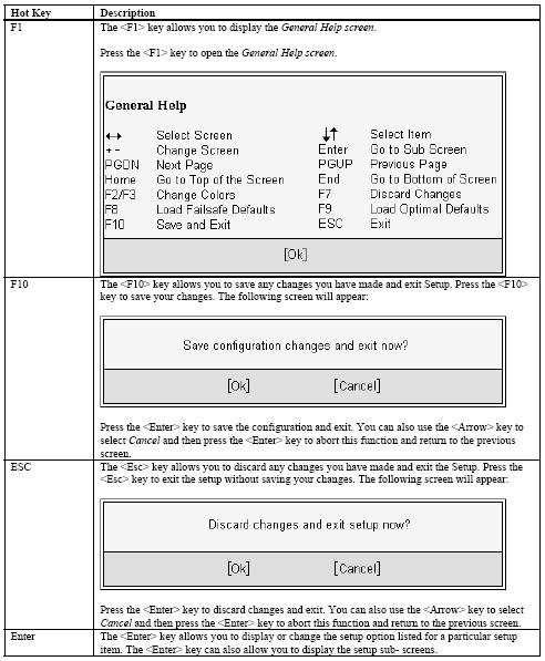
21 21
22 3. BIOS Setting 3.1. Main Menu When you first enter the Setup Utility, you will enter the Main setup screen. You can always return to the Main setup screen by selecting the Main tab. There are two Main Setup options. They are described in this section. In console mode: Press TAB key can into BISO setup man menu Press B key can popup device boot menu Press L key can boot from network 22

23 3.2. System Date / Time Use this page to change the system time and date. Highlight System Time or System Date using the <Arrow> keys. Enter new values through the keyboard. Press the <Tab> key or the <Arrow> keys to move between fields. The date must be entered in MM/DD/YY format. The time is entered in HH:MM:SS format. 23

24 3.3. System Information This page is show system information, for example BIOS Version Build Time.. etc Advanced BIOS Setup Select the Advanced tab from the setup screen to enter the Advanced BIOS Setup screen. You can select any of the items in the left frame of the screen, such as Super IO Configuration, to go to the sub menu for that item. You can display an Advanced BIOS Setup option by highlighting it using the <Arrow> keys. All Advanced BIOS Setup options are described in this section. The Advanced BIOS Setup screen is shown below. The sub menus are described on the following pages. 24


25 3.5. CPU Configuration You can use this screen to select options for the CPU Configuration. Use the up and down <Arrow> keys to select an item. Use the <Plus> and <Minus> keys to change the Value of the selected option. 25

26 3.6. SATA Configuration Setup From the SATA Configuration screen, press <Enter> to access the sub menu. Use the up and down <Arrow> keys to select an item. The settings are described on the following pages. 26

27 3.7. SUPER IO Configuration You can use this screen to select options for the Super I/O settings. Use the up and down <Arrow> keys to select an item. Use the <Plus> and <Minus> keys to change the value of the selected option. The settings are described on the following pages. The screen is Shown below. Power Loss Determines the state of the system after the return of power from an AC power loss. Default set Always On. Always Off: The system stays off upon the return of the AC power. Always On: The system is turned on upon the return of the AC power. 27
28 3.8. Console Redirection You can use this screen to select options for the Remote Access Configuration. Use the up and down <Arrow> keys to select an item. Use the <Plus> and <Minus> keys to change the value of the selected option. The settings are described on the following pages. The screen is shown below. Console Redirection You can disable or enable the BIOS console output function here. Terminal Type Select the terminal type you want to use. Default set VT100. Baudrate Select the Baudrate you want the serial port to use for console redirection. 28

29 3.9. USB Configuration You can use this screen to select options for the USB Configuration. Use the up and down <Arrow> keys to select an item. Use the <Plus> and <Minus> keys to change the value of the selected option. The settings are described on the following pages. The screen is shown below.. 29

30 3.10. Boot Setting Configuration Screen Boot Settings Configuration Use this screen to select options for the Boot Settings Configuration. Use the up and down <Arrow> keys to select an item. Use the <Plus> and <Minus> keys to change the value of the selected option. The settings are described on the following pages. The screen is shown below. Num-Lock Set this value to allow the Number Lock setting to be modified during boot up. The Optimal and Fail-Safe default setting is On. Quick Boot The Optimal and Fail-Safe default setting is Enabled. 30

31 3.11. Boot Device Priority Boot Device Priority Use this screen to specify the order in which the system checks for the device to boot from. To access this screen, select Boot Device Priority on the Boot Setup screen and press <Enter>. The following screen displays: 31

32 3.12. Exit Menu Select the Exit tab from the setup screen to enter the Exit BIOS Setup screen. You can display an Exit BIOS Setup option by highlighting it using the <Arrow> keys. All Exit BIOS Setup options are described in this section. The Exit BIOS Setup screen is shown below. Exit Saving Changes When you have completed the system configuration changes, select this option to leave Setup and reboot the computer so the new system configuration parameters can take effect. Select Exit Saving Changes from the Exit menu and press <Enter>. Exit Discarding Changes Select this option to quit Setup without making any permanent changes to the system configuration. Select Exit Discarding Changes from the Exit menu and press <Enter>. Load Setup Defaults Automatically sets all Setup options to a complete set of Default settings when you select this option. Select Load Optimal Defaults from the Exit menu and press <Enter>. Discard Changes Select Discard Changes from the Exit menu and press <Enter>. 32
CAF-1000 Series Communication Appliance. User s Manual Revision: 1.0
 CAF-1000 Series Communication Appliance User s Manual Revision: 1.0 CE This certificate of conformity of COS-0906 series with actual required safety standards in accordance with 89/366 ECC-EMC Directive
CAD-0205 Series Communication Appliance. User s Manual Revision: 1.4
 CAD-0205 Series Communication Appliance User s Manual Revision: 1.4 CE This certificate of conformity of CAD-0205 series with actual required safety standards in accordance with 89/366 ECC-EMC Directive
CAR-1001 Series Communication Appliance. User s Manual Revision: 1.0
 CAR-1001 Series Communication Appliance User s Manual Revision: 1.0 CE This certificate of conformity of CAR-1001 series with actual required safety standards in accordance with 89/366 ECC-EMC Directive
CAR-2000 Series Communication Appliance. User s Manual Revision: 1.0
 CAR-2000 Series Communication Appliance User s Manual Revision: 1.0 CE This certificate of conformity of CAR-2000 series with actual required safety standards in accordance with 89/366 ECC-EMC Directive
CAM-0100 Series Communication Appliance
 CAM-0100 Series Communication Appliance User s Manual Revision: 1.0 CE This certificate of conformity of CAM-0100 series with actual required safety standards in accordance with 89/366 ECC-EMC Directive
CAR-3006 Series Communication Appliance. User s Manual Revision: 1.1
 CAR-3006 Series Communication Appliance User s Manual Revision: 1.1 CE This certificate of conformity of CAR-3006 series with actual required safety standards in accordance with 89/366 ECC-EMC Directive
CAR-4000 Series Communication Appliance. User s Manual Revision: 1.1
 CAR-4000 Series Communication Appliance User s Manual Revision: 1.1 CE This certificate of conformity of CAR-4000 series with actual required safety standards in accordance with 89/366 ECC-EMC Directive
CAD-0210 Series Communications Appliance. Revision: 1.1
 CAD-0210 Series Communications Appliance User s Manual Revision: 1.1 CE This certificate of conformity of CAD-0210 series with actual required safety standards in accordance with 89/366 ECC-EMC Directive
CAR-3030 Series Communication Appliance CAR F90 / CAR F90
 CAR-3030 Series Communication Appliance CAR-3030-3600-F90 / CAR-3030-3200-F90 User s Manual Revision: 1.0 Table of Contents Chapter 1 Introduction... 3 1.1 About This Manual... 3 1.2 Manual Organization...!
CAR-3030 Series Communication Appliance
 CAR-3030 Series Communication Appliance User s Manual Revision: 1.0 頁 1 Table of Contents Chapter 1 Introduction... 3 1.1 About This Manual... 3 1.2 Manual Organization... 3 1.4 Board Layout... 4 1.5 System
NAR-7060 Communication Appliance
 NAR-7060 Communication Appliance User s Manual Revision: 010 Portwell Inc. 3F, No. 92, Sec. 1, Nei-Hu Rd., Taipei 114, Taiwan, R.O.C. Headquarter: +886-2-2799-2020 FAX: +886-2-2799-1010 http://www.portwell.com.tw
NAR-5520 Series Communication Appliance. User s Manual Revision: 1.2
 NAR-5520 Series Communication Appliance User s Manual Revision: 1.2 CE This certificate of conformity of NAR-5520 series with actual required safety standards in accordance with 89/366 ECC-EMC Directive
MIL-STD Rugged Computer User's Manual. Version 1.0 Revision Date: July. 05, 2017 THOR200. MIL-STD Rugged Computer
 THOR200 MIL-STD Rugged Computer Safety information Electrical safety To prevent electrical shock hazard, disconnect the power cable from the electrical outlet before relocating the system. When adding
8806 Series. 15 Multi-functional Touch Panel PC. Quick Reference Guide
 8806 Series 15 Multi-functional Touch Panel PC Quick Reference Guide 1st Ed 10 July, 2009 8806 Contents 1. Getting Started...3 1.1 Safety Precautions...3 1.2 Packing List...3 1.3 System Specifications...4
AMS Series. Fanless System
 AMS100-807 Series Fanless System User s Manual Version 1.0 Table of Contents Chapter 1 Specifications... 3 Chapter 2 AMS100-807 Series Features... 4 Chapter 3 System Dimensions... 5 Chapter 4 Opening the
WG 10 /12 Series. Quick Reference Guide /12.1 Multifunctional Touch Panel PC. Copyright Notice
 10.4 /12.1 Multifunctional Touch Panel PC Quick Reference Guide Copyright Notice Copyright 2007-2009 Technology Inc., ALL RIGHTS RESERVED. Part No. E20171203A0R Contents 1. Getting Started...3 1.1 Safety
User Guide Guangzhou Zhiyuan Electronics Stock Co., LTD
 Platform EPCM-505C User Guide Guangzhou Zhiyuan Electronics Stock Co., LTD Safety information Electrical safety To prevent electrical shock hazard, disconnect the power cable from the electrical outlet
LVN5200A-R2, rev. 1, Hardware Installation Guide
 LVN5200A-R2 LVN5250A-R2 LVN5200A-R2, rev. 1, Hardware Installation Guide Customer Support Information Order toll-free in the U.S.: Call 877-877-BBOX (outside U.S. call 724-746-5500) FREE technical support
LPC-08 Series. Quick Reference Guide. 8 Multi-functional Touch Panel PC. Copyright Notice. 2 nd Ed May 2010
 8 Multi-functional Touch Panel PC Quick Reference Guide 2 nd Ed May 2010 Copyright Notice Copyright 2010 Avalue Technology Inc., ALL RIGHTS RESERVED. Part No. E201708A1A1R Contents 1. Getting Started...3
VL BPC 100. Valueline configurable box PC. Data sheet 3063_en_E. 1 Description. 2 Features
 Valueline configurable box PC Data sheet 0_en_E Description PHOENIX CONTACT 0-07- Features The VL BPC 000 is a configurable box PC that can be mounted either directly on a wall or on a DIN rail. The VL
EPC-APL. Quick Reference Guide. Intel Pentium /Celeron Processor Fanless Tiny System. Copyright Notice. 1 st Ed 12 September 2017
 Intel Pentium /Celeron Processor Fanless Tiny System Quick Reference Guide 1 st Ed 12 September 2017 Copyright Notice Copyright 2017 ALL RIGHTS RESERVED. Part No. E2017CAI0A0R FCC Statement THIS DEVICE
MPC 21 Series. Quick Reference Guide. 21 Multifunctional Touch Panel PC. 1 st Ed 28 october Part No. E201721W3A1R
 21 Multifunctional Touch Panel PC Quick Reference Guide 1 st Ed 28 october 2010. Part No. E201721W3A1R 1. Getting Started 1.1 Safety Precautions Warning! Always completely disconnect the power cord from
CAR-4003 Series Communication Appliance. User s Manual Revision: 1.1
 CAR-4003 Series Communication Appliance User s Manual Revision: 1.1 Table of Contents Chapter 1 Introduction...2 1.1 About This Manual... 2 1.2 Manual Organization... 2 1.3 Technical Support Information...
Colorful Technology Website:
 Colorful Technology Website: http://www.colorful.cn Thanks for purchasing our based on Intel B250 Chipset motherboard. The motherboard C.B250A-BTC PLUS V20 based on Intel B250 Express Chipset, support
Installing the Cisco Unified Videoconferencing 3545 MCU
 CHAPTER 2 Installing the Cisco Unified Videoconferencing 3545 MCU The Cisco Unified Videoconferencing 3545 MCU works together with a Cisco Unified Videoconferencing 3545 EMP Enhanced Media Processor (EMP)
PIX 520. PIX 520 Product Overview CHAPTER
 CHAPTER 5 PIX 520 This chapter guides you through the installation of the PIX 520, and includes the following sections: PIX 520 Product Overview, page 5-1 Installing the PIX 520, page 5-4 PIX 520 Feature
VL BPC MINI. A configurable industrial computer platform. Data sheet 2930_en_F. 1 Description. 2 Features
 A configurable industrial computer platform Data sheet 90_en_F Description PHOENIX CONTACT 0-08- Features The VL BPC MINI is an embedded box PC and is part of the Valueline family of industrial computers.
Rugged Panel PC AcuPanel 12 User Manual Revision 2.0
 ACURA EMBEDDED SYSTEMS INC. Rugged Panel PC AcuPanel 12 User Manual Revision 2.0 Contents Chapter 1: AcuPanel 12 Overview Specifications... 2 Knowing AcuPanel 12... 4 Rear Top... 4 Rear Bottom... 5 Rear
VL BPC MINI. A configurable industrial computer platform Intel Atom Z510PT CMAT IPC Module Option [I28] AUTOMATION Data Sheet 2930_en_A.
![VL BPC MINI. A configurable industrial computer platform Intel Atom Z510PT CMAT IPC Module Option [I28] AUTOMATION Data Sheet 2930_en_A.](/thumbs/72/66783612.jpg "VL BPC MINI. A configurable industrial computer platform Intel Atom Z510PT CMAT IPC Module Option [I28] AUTOMATION Data Sheet 2930_en_A.") A configurable industrial computer platform Intel Atom Z0PT CMAT IPC Module Option [I8] AUTOMATION Data Sheet 90_en_A Description PHOENIX CONTACT 0-0-0 Features The VL BPC MINI is an embedded box PC and
A configurable industrial computer platform Intel Atom Z0PT CMAT IPC Module Option [I8] AUTOMATION Data Sheet 90_en_A Description PHOENIX CONTACT 0-0-0 Features The VL BPC MINI is an embedded box PC and
Industrial PC IPC191V2. General Operating, Maintenance and Installation Manual. Hardware Platform Protocol Converter
 Industrial PC IPC191V2 General Operating, Maintenance and Installation Manual Hardware Platform Protocol Converter D-91056 Erlangen Phone: +49 9131 7677 47 Fax: +49 9131 7677 78 Internet: http://www.ipcomm.de
ACS-2630 Box PC User Manual
 ACS-2630 Box PC User Manual Release Date Revision June 2006 V0.1 2005 Aplex Technology, Inc. All Rights Reserved. Published in Taiwan Aplex Technology, Inc. 9F-5, No. 2, Jian Pa Road, Chung Ho City, Taipei
FPC 08W Series. 8 Widescreen Multi-functional Touch Panel PC. Quick Reference Guide. 2 nd Ed 28 June, 2010
 FPC 08W Series 8 Widescreen Multi-functional Touch Panel PC Quick Reference Guide 2 nd Ed 28 June, 2010 Copyright Notice Copyright 2010 Avalue Technology Inc., ALL RIGHTS RESERVED. Part No. E201708WAA1R
Packing List. Optional Accessories. Specifications. General. MIOe Expansion Slot. 64-pin Expansion Connectors. MIO-3260 Startup Manual 1
 MIO-3260 Intel Atom TM E3825 & Celeron N2930 Pico-ITX SBC, with DDR3L, 18/24-bit LVDS, VGA, DP/HDMI, GbE, Fullsize Mini PCIe, 4 USB, 2 COM, SMBus, I2C, msata & MIOe Startup Manual Packing List Before you
Specifications. Packing List. Ethernet Interface. General. MIOe Expansion Slot. VGA/HDMI Interface. MIO-2360 Startup Manual 1
 MIO-236 Intel Celeron N335/Atom E394/ Atom E393 Pico-ITX SBC, DDR3L, 24-bit LVDS, VGA/HDMI, 1 GbE, Full-size Mini PCIe, 4 USB, 2 COM, SMBus, msata & MIOe Startup Manual Packing List Before you begin installing
Rugged Panel PC AcuPanel 17 User Manual Revision 1.5
 ACURA EMBEDDED SYSTEMS INC. Rugged Panel PC AcuPanel 17 User Manual Revision 1.5 Contents Chapter 1: AcuPanel 17 Overview Specifications... 2 Knowing AcuPanel 17... 4 Rear Top... 4 Rear Bottom... 5 Rear
LifeSize ClearSea Installation Guide August 2012
 LifeSize ClearSea Installation Guide August 2012 LifeSize ClearSea LifeSize ClearSea Virtual Machine LifeSize ClearSea Installation Guide 2 LifeSize ClearSea This guide describes how to install and configure
KEEX-7100 Series Single Board Computer in 3.5" ECX Form Factor with Intel Ivy Bridge Processors
 Single Board Computer in 3.5" ECX Form Factor with Intel Ivy Bridge Processors Intel Intel Ivy Bridge UE Processor Intel QM77/ HM76 Express Chipset 1x DDR3 SO-DIMM 2x SATA, 1x msata for Storage 2x LVDS,
PIX 515/515E. PIX 515/515E Product Overview CHAPTER
 CHAPTER 4 PIX 515/515E This chapter describes how to install the PIX 515/515E, and includes the following sections: PIX 515/515E Product Overview Installing a PIX 515/515E PIX 515/515E Feature Licenses
TEOS Hardware System TEOS 8416 / TEOS 1016/ TEOS1216
 TEOS Hardware System TEOS 8416 / TEOS 1016/ TEOS1216 Revision v1.1 November 2011 Copyright 2009~2011 All Rights Reserved Manual Version 1.1 The information contained in this document is subject to change
NAR-7102 Series Communication Appliance. User s Manual Revision: 1.0
 NAR-7102 Series Communication Appliance User s Manual Revision: 1.0 CE This certificate of conformity of NAR-7102 series with actual required safety standards in accordance with 89/366 ECC-EMC Directive
Junos WebApp Secure 5.0 Hardware Guide
 Junos WebApp Secure 5.0 Hardware Guide Junos WebApp Secure 5.0 Hardware Guide This document contains a specification for the MWS1000 hardware appliance, as well as instructions for installation into a
Ollee Ultra Mini PC, a Mini PC with 32GB emmc and Windows 10 Pro MAPMG. Ollee Ultra Mini PC, a Mini PC with 120GB SSD and Windows 10 Pro MAPMG1
 Ollee Ultra Mini PC, a Mini PC with 32GB emmc and Windows 10 Pro MAPMG Ollee Ultra Mini PC, a Mini PC with 120GB SSD and Windows 10 Pro MAPMG1 User Guide Before You Begin CAUTIONS The procedures in this
MITAC Desktop Board PD10TI Product Guide
 MITAC Desktop Board PD10TI Product Guide Desktop Board Features This chapter briefly describes the main features of MITAC Desktop Board PD10TI. Table 1 summarizes the features of the Desktop Board. TABLE
MITAC Desktop Board PD12TI Product Guide
 MITAC Desktop Board PD12TI Product Guide Desktop Board Features This chapter briefly describes the main features of MITAC Desktop Board PD12TI. Table 1 summarizes the features of the Desktop Board. Table
Industrial PC IPC191C2. General Operating, Maintenance and Installation Manual. Hardware Platform Protocol Converter
 Industrial PC IPC191C2 General Operating, Maintenance and Installation Manual Hardware Platform Protocol Converter D-91056 Erlangen Phone: +49 9131 7677 47 Fax: +49 9131 7677 74 Internet: http://www.ipcomm.de
4170 POS System Installation Guide
 4170 POS System 4170 Installation Guide Thank you for selecting UTC RETAIL s innovative Model 4170 Point of Sale solution! This Installation Guide will help you efficiently install the 4170 POS. The document
Lightspeed Advanced Reporting Bottle Rocket Hardware Installation Guide
 Lightspeed Advanced Reporting Bottle Rocket Hardware Installation Guide 1800 19th Street / Bakersfield, CA 93301 / Tel: 661.716.7600 / Toll Free: 877.447.6244 / www.lightspeedsystems.com Table of Contents
PCA-6781 ISA Celeron M Half-sized SBC with VGA/ LCD/LVDS/10/100 Ethernet/USB2.0 and SSD Startup Manual
 PCA-6781 ISA Celeron M Half-sized SBC with VGA/ LCD/LVDS/10/100 Ethernet/USB2.0 and SSD Startup Manual Packing List Specifications Before you begin installing your card, please make sure that the following
GOT3126T-832. All-in-One 12.1 SVGA TFT Fanless Compact-Size PANEL PC. User s Manual
 GOT3126T-832 All-in-One 12.1 SVGA TFT Fanless Compact-Size PANEL PC User s Manual Disclaimers This manual has been carefully checked and believed to contain accurate information. Axiomtek Co., Ltd. assumes
General. Display. Ethernet Interface. MIO-5271 Startup Manual 1
 MIO-5271 3.5 MI/O-Compact SBC, Intel Core U-series (i5/celeron ), DDR3L, VGA, HDMI/DP, 48-bit LVDS, 2 x GbE, 2 x Mini PCIe, msata, Fanless, imanager, MIOe Startup Manual Packing List Before you begin installing
FPC 10W/13W Series 10 /13 Widescreen Multi-functional Touch Panel PC
 FPC 10W/13W Series 10 /13 Widescreen Multi-functional Touch Panel PC Quick Reference Guide 2 nd Ed 03 June, 2009 Copyright Notice Copyright 2007-2009 Avalue Technology Inc., ALL RIGHTS RESERVED. Part No.
Installing the IPS 4345 and IPS 4360
 CHAPTER 4 Installing the IPS 4345 and IPS 4360 Contents This chapter describes the Cisco IPS 4345 and the IPS 4360, and includes the following sections: Installation Notes and Caveats, page 4-1 Product
Installation Manual of DS-9600NI-H8 DS-9600NI-H8. Installation Manual UD.7L0202A1730B01
 DS-9600NI-H8 Installation Manual UD.7L0202A1730B01 1 Thank you for purchasing our product. If there is any question or request, please do not hesitate to contact dealer. Before you start, read the following
Chapter 6 Cubix SP1 Blade Server
 Chapter 6 Cubix SP1 Blade Server Introduction Cubix designed the SP1 Blade Server to fit inside a BladePoint or BladeStation enclosure. The Blade Server features the Intel Pentium 4 processor, the Intel
1.1.Packing Contents 1*Colorful C.B250A-BTC V20 motherboard 2*SATA cables 1*Driver/Utility CD 1*User's Guide 1*I/O shield 1.2.MOTHERBOARD SPEC CPU
 Colorful Technology Website: http://www.colorful.cn Thanks for purchasing our based on Intel B250 Chipset motherboard. The motherboard C.B250A-BTC V20 based on Intel B250 Express Chipset, support Intel
Manual AMS ibase
 Manual AMS100-807 ibase Our company network supports you worldwide with offices in Germany, Austria, Switzerland, Great Britain and the USA. For more information please contact: FORTEC Elektronik AG Hauptniederlassung
Network Application Platform. User s Manual
 525 Network Application Platform User s Manual Rev:1.0 Date:2012.03 CONTENTS CHAPTER 1 PACKAGE CONTENTS... 3 CHAPTER 2 INTRODUCTION... 4 CHAPTER 3 LAYOUT... 5 CHAPTER 4 REAR PANEL SKETCH MAP... 5 CHAPTER
ITA-1711 Series Fanless Compact Embedded IPC with Intel Celeron Dual Core CPU Startup Manual
 ITA-1711 Series Fanless Compact Embedded IPC with Intel Celeron Dual Core CPU Startup Manual Packing List Specifications Before you begin installing your IPC, please make sure that the following items
Thank you for selecting UTC RETAIL s innovative Model 1170 Point of Sale solution!
 1170 POS SYSTEM 1170 USER GUIDE Thank you for selecting UTC RETAIL s innovative Model 1170 Point of Sale solution! This guide is designed to acquaint you with the features and functionality of the 1170
PTBG965EFN LF. User Manual. English PTBG965EFN LF. Mainboard Manual
 Mainboard Manual 1 Copyright Copyright 2006 FIC (First International Computer) Incorporated All rights reserved. Disclaimer: FIC Inc. shall not be liable for technical or editorial errors or omissions
After completing this chapter, you will meet these objectives:
 3.0 Introduction Assembling computers is a large part of a technician's job. As a technician, you will need to work in a logical, methodical manner when working with computer components. As with any learned
NAR-7100 Series Communication Appliance. User s Manual Revision: 1.2
 NAR-7100 Series Communication Appliance User s Manual Revision: 1.2 CE This certificate of conformity of NAR-7100 series with actual required safety standards in accordance with 89/366 ECC-EMC Directive
FWA-6280A User Manual 1. FWA-6280A User Manual
 1 Copyright Notice This document is copyrighted, 2005. All rights are reserved. The original Manufacturer reserves the right to make improvements to the products described in this manual at any time without
EVGA assumes you have purchased all necessary parts needed to allow for proper system functionality.
 Before You Begin Parts NOT in the Kit This kit contains all the hardware necessary to install and connect your new EVGA e-7050/610i GPU motherboard with integrated GeForce graphics processing. However,
SB1015W Widescreen All-in-one POS Terminal USER MANUAL
 SB1015W Widescreen All-in-one POS Terminal USER MANUAL Table of Contents 1 Introduction...2 1.1 Safety Information... 2 1.2 Electromagnetic compatibility statement... 3 2 Overview... 4 2.1 Features...
Industrial PC IPC191V3 (Linux OS) IPC191V3WIN (Windows OS) General Operating, Maintenance and Installation Manual
 IPC191V3WIN (Windows OS) General Operating, Maintenance and Installation Manual") Industrial PC IPC191V3 ( OS) IPC191V3WIN (Windows OS) General Operating, Maintenance and Installation Manual Hardware Platform Protocol Converter D-91056 Erlangen Phone: +49 9131 92076-0 Fax: +49 9131
Industrial PC IPC191V3 ( OS) IPC191V3WIN (Windows OS) General Operating, Maintenance and Installation Manual Hardware Platform Protocol Converter D-91056 Erlangen Phone: +49 9131 92076-0 Fax: +49 9131
Intel NUC Kit DN2820FYKH User Guide. Intel NUC Kit DN2820FYKH User Guide
 Intel NUC Kit DN2820FYKH User Guide 1 Before You Begin CAUTIONS The procedures in this user guide assume familiarity with the general terminology associated with personal computers and with the safety
EVO-TP Hardware System
 User Manual Revision v1.3 February 2010 EVO-TP Hardware System Copyright 2009 February All Rights Reserved Manual Version 1.1 Part Number: The information contained in this document is subject to change
GOT3157W-832-PCT. All-in-One 15.6 WXGA TFT Fanless Compact-Size PANEL PC. User s Manual
 GOT3157W-832-PCT All-in-One 15.6 WXGA TFT Fanless Compact-Size PANEL PC User s Manual Disclaimers This manual has been carefully checked and believed to contain accurate information. Axiomtek Co., Ltd.
GS-SR104 Rack Mount Server System Installation Guide
 GS-SR104 Rack Mount Server System Installation Guide 1-i INDEX 1. INTRODUCTION 1-1 1.1. PREFACE 1-1 1.2. FEATURES 1-1 2. HARDWARE INVENTORY 2-1 3. SYSTEM INSTALLATION PROCEDURES 3-1 3.1. CHASSIS COVER
AIMB-210 (Intel Atom processor N GHz FSB 533 MHz Mini-ITX Motherboard with VGA, LVDS, TV-Out, 6 COM, Dual GbE, 8 USB, 2 SATA II) Startup Manual
 Startup Manual") AIMB-210 (Intel Atom processor N270 6 GHz FSB 533 MHz Mini-ITX Motherboard with VGA, LVDS, TV-Out, 6 COM, Dual GbE, 8 USB, 2 SATA II) Startup Manual Before you begin installing your card, please make sure
AIMB-210 (Intel Atom processor N270 6 GHz FSB 533 MHz Mini-ITX Motherboard with VGA, LVDS, TV-Out, 6 COM, Dual GbE, 8 USB, 2 SATA II) Startup Manual Before you begin installing your card, please make sure
PIX 535. PIX 535 Product Overview CHAPTER
 CHAPTER 7 PIX 535 This chapter describes the installation of the PIX 535, and includes the following sections: PIX 535 Product Overview Installing a PIX 535 PIX 535 Feature Licenses Installing Failover
Dell Networking S4810 Open Networking (ON) Getting Started Guide
 Getting Started Guide") Dell Networking S4810 Open Networking (ON) Getting Started Guide Regulatory Model: S4810 Notes, Cautions, and Warnings NOTE: A NOTE indicates important information that helps you make better use of your
Dell Networking S4810 Open Networking (ON) Getting Started Guide Regulatory Model: S4810 Notes, Cautions, and Warnings NOTE: A NOTE indicates important information that helps you make better use of your
XE 900: Fastest EPIC board now available with Windows XPe
 XE 900: Fastest EPIC board now available with Windows XPe The XE 900 SBC is a high performance, low power, x86 workhorse for embedded applications. It is an EPIC form factor SBC with a rich family of I/O
ARP992/ ARP992-B User Reference Manual
 ARP992/ ARP992-B User Reference Manual Specifications Model No ARP992 ARP992-B CPU Intel Core i5-7440eq, 2.90GHz Processors Option: Intel Core i7-7820eq, 3.0 GHz Chipset Intel 7th Gen. Core i5 /i7 processors
Installing the Cisco ADE 2130 and 2140 Series Appliance Hardware Options
 CHAPTER 4 Installing the Cisco ADE 2130 and 2140 Series Appliance Hardware Options This chapter provides instructions for installing, replacing, and removing various hardware options in your Cisco ADE
Intel NUC Kit NUC5i3MYHE & NUC5i5MYHE User Guide. Intel NUC Kit NUC5i3MYHE Intel NUC Kit NUC5i5MYHE User Guide
 Intel NUC Kit NUC5i3MYHE Intel NUC Kit NUC5i5MYHE User Guide 1 Before You Begin CAUTIONS The procedures in this user guide assume familiarity with the general terminology associated with personal computers
Installation Manual of DS-7600NI-H2/P Series. DS-7600NI-H2/P Series. Installation Manual UD.7L0202D1761B01
 DS-7600NI-H2/P Series Installation Manual UD.7L0202D1761B01 1 Thank you for purchasing our product. If there is any question or request, please do not hesitate to contact dealer. Before you start, read
KEEX-5100 Series Standard / Extended Temperature Single Board Computer in 3.5" ECX Form Factor with Intel Haswell / Broadwell ULT Processors
 Standard / Extended Temperature Single Board Computer in 3.5" ECX Form Factor with Intel Haswell / Broadwell ULT Processors 4th /5th Gen. Intel Haswell / Broadwell ULT Processor 1x DDR3L SO-DIMM Socket
Computer Assembly Step by Step DRAFT
 9781587132636_ch03.qxp 8/20/10 1:37 PM Page 79 CHAPTER 3 Computer Assembly Step by Step Objectives Upon completion of this chapter, you should be able to answer the following questions: How do I open the
User Guide for NUC7CJYSAL. Intel NUC 7 Essential, a Mini PC with Windows 10 NUC7CJYSAL. User Guide
 Intel NUC 7 Essential, a Mini PC with Windows 10 NUC7CJYSAL User Guide 1 Before You Begin CAUTIONS The procedures in this guide assume familiarity with the general terminology associated with personal
PCM-4381 Intel Pentium M EPIC SBC with VGA/2 LVDS/ 2 Ethernet/ 4 COM/ 2 SATA/6 USB 2.0/ 16 bit GPIO
 PCM-4381 Intel Pentium M EPIC SBC with VGA/2 LVDS/ 2 Ethernet/ 4 COM/ 2 SATA/6 USB 2.0/ 16 bit GPIO Before you begin installing your card, please make sure that the following items have been shipped: 1.
Features. -40 ~ 60 95% humidity (non-condensing) 40 C (non-condensing) Vibration
 40 C (non-condensing) Vibration") MIC-7300 NEW Compact Fanless System with Intel Celeron N3350/Atom x7-e3950 Processor Features Intel Celeron N3350/Atom x7-e3950 processor 2 x RS-232/422/485 and 4 x RS232 serial ports (with expansion cable)
MIC-7300 NEW Compact Fanless System with Intel Celeron N3350/Atom x7-e3950 Processor Features Intel Celeron N3350/Atom x7-e3950 processor 2 x RS-232/422/485 and 4 x RS232 serial ports (with expansion cable)
Setting Up Your Cisco Unified Videoconferencing 3515 MCU
 CHAPTER 2 Setting Up Your Cisco Unified Videoconferencing 3515 MCU This section describes the following topics: Physical Description, page 2-1 Preparing for Installation, page 2-2 Verifying the Package
EX-96XX6A HMI User Manual
 EX-96XX6A HMI User Manual Release Date Revision Nov 2011 V1.0 2011 All Rights Reserved. Published in Taiwan EX-96XX6A User Manual 1 Warning! This equipment generates, uses and can radiate radio frequency
GOT3846T-832 All-in-One 8.4 SVGA TFT Fanless Compact-Size PANEL PC User s Manual
 GOT3846T-832 All-in-One 8.4 SVGA TFT Fanless Compact-Size PANEL PC User s Manual Disclaimers This manual has been carefully checked and believed to contain accurate information. Axiomtek Co., Ltd. assumes
Intel NUC Kit D54250WYKH & D34010WYKH User Guide. Intel NUC Kit D54250WYKH Intel NUC Kit D34010WYKH User Guide
 Intel NUC Kit D54250WYKH Intel NUC Kit D34010WYKH User Guide 1 Before You Begin CAUTIONS The procedures in this user guide assume familiarity with the general terminology associated with personal computers
Intel NUC Kit DC53427HYE User Guide. Intel NUC Kit DC53427HYE
 Intel NUC Kit DC53427HYE User Guide 1 Before You Begin CAUTIONS The procedures in this user guide assume familiarity with the general terminology associated with personal computers and with the safety
User s Manual ITR-CS15D
 User s Manual ITR-CS15D Copyrights 2012 TALOS INTEGRATED TECHNOLGIES. All rights reserved. The information in this document is subject to change without prior notice in order to improve reliability, design
PPC-F-Q370 SERIES AI Ready Panel PC Based on Intel OpenVINO toolkit
 PPC-F-Q370 SERIES AI Ready Panel PC Based on Intel OpenVINO toolkit 15 Motorcycle 48 CAR 305 CAR 304 People 32 CAR 308 CAR 401 17 15.6 18.5 21.5 23.8 CAR 306 CAR 307 CAR 309 CAR 308 CAR 400 CAR 402 CAR
Troubleshooting the System Hardware
 CHAPTER 5 This chapter provides basic troubleshooting information to help you identify some common problems that might occur with your Wide Area Virtualization Engine (WAVE). This chapter contains the
RCO Compact Rugged Fanless System with Intel Atom E3827/E3845 or Celeron J1900
 RCO-1000 Compact Rugged Fanless System with Intel Atom E3827/E3845 or Celeron J1900 FEATURES Intel Atom Processor E3827, E3845, or Celeron J1900 1x 204-pin DDR3L SO-DIMM, up to 8GB Dual independent display
PCM-9365 Intel Celeron N2930 & Atom E3825, 3.5 SBC, 2GB/4GB On-board Memory, VGA, 48-bit LVDS, 2GbE, Mini PCIe, PCI-104, SUSI 4 Startup Manual
 PCM-9365 Intel Celeron N293 & Atom E3825, 3.5 SBC, 2GB/4GB On-board Memory, VGA, 48-bit LVDS, 2GbE, Mini PCIe, PCI-14, SUSI 4 Startup Manual Packing List Before you begin installing your card, please make
Replacing the RAID Battery Backup Unit Assembly on Series 3 FireSIGHT 3500 Defense Centers, Version 5.x
 Replacing the RAID Battery Backup Unit Assembly on Series 3 FireSIGHT 3500 Defense Centers, Version 5.x Last Updated: December 4, 2014 Use these instructions to replace the RAID battery backup unit (BBU)
ECX-SLU0 / KLU0 Series
 Standard / Extended Temperature Single Board Computer in 3.5" ECX Form Factor with Intel Skylake / Kaby Lake U-Series Processors Intel Skylake / Kaby Lake U-Series Processors 2x DDR4 SO-DIMM 1x LVDS, 1x
PPC-F-Q370 SERIES. OpenVINO. AI Ready Panel PC Based on Intel OpenVINO toolkit AR 501 CAR 500 CAR 406 CAR 407 CAR 408 CAR 409 CAR 404 CAR 405 CAR 402
 PPC-F-Q370 SERIES AI Ready Panel PC Based on Intel OpenVINO toolkit Motorcycle 48 CAR 305 CAR 304 People 32 CAR 308 CAR 401 CAR 306 CAR 307 CAR 309 CAR 308 CAR 400 CAR 402 CAR 403 Motorcycle 48 Motorcycle
ReadyNAS Rack-Mount Storage Systems
 ReadyNAS Rack-Mount Storage Systems Hardware Manual Models: 1500 2100 3100 3200 4200 350 East Plumeria Drive San Jose, CA 95134 USA May 2011 202-10848-01 2011 NETGEAR, Inc. All rights reserved. No part
MN525RI MN525MI. User's Manual. Intel D525 Processor Motherboards. Rev. 1001
 MN525RI MN525MI Intel D525 Processor Motherboards User's Manual Rev. 1001 Copyright 2010 GIGA-BYTE TECHNOLOGY CO., LTD. All rights reserved. The trademarks mentioned in this manual are legally registered
VTPC190V / VS / VDC / VSDC
 Solutions for Demanding Applications VARTECH S Y S T E M S I N C. 19.0 Enclosed VESA Mount PC Model VTPC190V / VS / VDC / VSDC User s Guide Read these instructions completely before attempting to operate