Installation Instructions
|
|
|
- Naomi Williamson
- 6 years ago
- Views:
Transcription
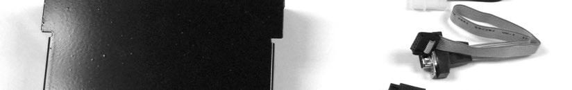
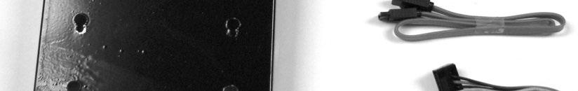
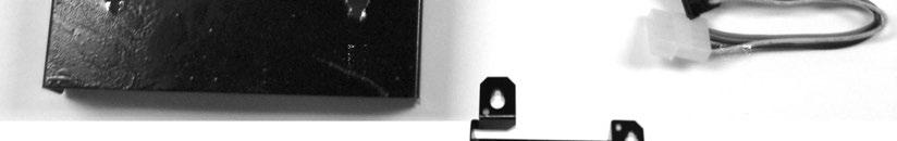
1 Installation Instructions Kit Core Upgrade-EMB-B75B Without Modem Kit # These instructions outline the procedures to install the EMB-B75B motherboard into your existing Computer Core Chassis. There may be unused parts in this kit depending on the style of Core being upgraded. Tools Required 1/4 and 11/32 nut driver, #2 Philips Screw driver Parts Included with this Kit: Item # Part Number Description Quantity Computer Board Assy EMB-B75B SATA Hard Drive U.S Bracket Hard Drive Tray Replacement Bracket SATA Mounting Adapter Cover Computer Card (Not Shown) Cover PSI Low Profile (Not Shown) Power On/Reset CBA Cable Assembly ON/Reset Harness Assembly ATX Power Cable Assembly DB EC Cable SATA Data 1 12 EC Harness SATA Power DB9 Hardware (Not Shown) #6-32 x ¼ Phillips (Not Shown) #4-40 x ¼ Phillips (Not Shown) M3 x 6 Phillips (Not Shown) Tie Wrap (Not Shown) Bracket Mounting (Hard Drive) 1 These Instructions NOTE: If you are installing this kit into a Blue View Core Computer assembly, you will need to order one additional harness. Order part number Page 1 of 12


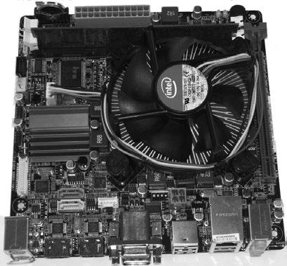
2 Figure 1 Page 2 of 12
3 Caution: When installing this EMB-B75B motherboard, care should be taken to avoid static discharges that can damage the motherboard. The motherboard installation should be done on a static dissipative mat along with a grounding wrist strap. Removing the Motherboard and ON/OFF reset board 1. Turn the jukebox off and unplug the power cord from the wall outlet. 2. Open the jukebox door and disconnect all the harnessing to the Computer Core. Note where the cables plug into the Computer Core Assembly for later reinstallation. Remove the Computer Core from the jukebox. 3. Rowe has six major Computer Cores as shown in Figure 2. Each Core has slightly different variations (fans, lights, etc.) depending on your jukebox model. It is important to note these variations and ensure they are connected after the motherboard installation. Figure 2 4. Remove all necessary components and covers to access the motherboard. Unplug and remove all ribbon cables from the motherboard. Disconnect all of the ATX power supply connections and the IDE Cable from the hard drive. Remove the modem card and its PCI cover (if present) from the motherboard; they will not be reused. Replacement PCI Covers (Items #5 and #6) are provided in this kit. 5. Remove the old ON/OFF reset board (340524XX) and the DB9 cable assembly from its mounting bracket; they will not be reused. Save the mounting bracket and hardware for later use. 6. Remove the seven screws that secure the motherboard to the core chassis. The motherboard and the front panel will not be reused; save the screws for later use. Page 3 of 12
 with the four existing studs on the computer core chassis.")
4 Installing the EMB-B75B Motherboard and ON/OFF reset board 7. Insert the front panel into position and carefully align the new motherboard (Item #1) with the four existing studs on the computer core chassis. Secure the motherboard with four of the seven screws removed in step #6. 8. Mount the ON/OFF reset board (Item #7) and the DB9 Cable Assembly (Item #10) and its hardware (Item #13) to your previously removed mounting bracket and reinstall into your Computer Core. Connect the ON/RESET cable (Item #8) into the keyed 10-pin header of the ON/RESET circuit board assembly. Refer to Figure Figure 3 shows all the electrical connections to your new motherboard. Connect the two ribbon cables as shown in Figure 3. Connect the 20-pin connector to the 24-pin housing on the motherboard. If your ATX power supply does not have the 4-pin connector, use the ATX Power Harness (Item #9) provided with this kit. If you have a chassis fan, connect it to a spare 4-pin connector of the ATX power supply. Refer to Figure PIN ATX POWER SUPPLY CONNECTION CONNECTIONS EC SATA/POWER CONNECTION EC ON/RESET CABLE CONNECTIONS DB9 SERIAL CABLE Note: FOR BLUE VIEW CORE USE SERIAL CABLE (not included in this kit) Figure 3 4-PIN ATX POWER SUPPLY CONNECTION Page 4 of 12
5 Assembling the SATA Hard Drive with the Adapter Mounting Bracket 10. Secure the SATA hard drive (Item #2) to the SATA Mounting Adapter Bracket (Item #4) using the four M3 x 6 metric screws (Item #16) as shown in Figure 4. HARD DRIVE M3X6 METRIC SCREWS (TWO ON EITHER SIDE) ADAPTOR BRACKET Figure 4 The following pages describe installing the hard drive in the different computer core models. Continue to the step # relating to the core you are reworking XX Step XX Step Step Step A Step 17 View Core Step 18 Connecting the SATA Hard Drive to the XX Series Computer Core 11. Disconnect the 4-pin power cable and IDE cable from the hard drive tray. Remove the four screws that mount the hard drive tray. The tray will not be reused, but you must save the screws for use in the following step. See Figure 4. REMOVE THE SCREWS TWO ON EITHER SIDE REMOVE POWER AND IDE CABLES Figure 5 Page 5 of 12
 on the inside cover of your computer core using")


6 12. Mount the replacement Hard Drive Tray Bracket (Item #3) on the inside cover of your computer core using the four screws previously removed. Ensure the bracket properly covers the front opening. Thread the four 6-32 x ¼ screws (Item #14) into the mounting adapter leaving approximately 1/16-inch gap. Insert the screw heads through the four keyholes on the hard drive tray replacement bracket and slide the hard drive down to secure it into the slots. Tighten the four screws. See Figure Connect the SATA/Power Cable EC (Item #12) to a 4-pin connector of the ATX power supply. Connect the SATA/Data Cable EC (Item #11) to the motherboard. Refer to Figure 3 for motherboard connections. Continue with step #19. FOUR KEYHOLES HARD DRIVE REPLACEMENT TRAY SATA/POWER CABLE Figure 6 Page 6 of 12


 to a 4-pin connector")
 to the")
7 Connecting the SATA Hard Drive to the XX Series Computer Core. 14. Disconnect the power and IDE Cables from the hard drive. Loosen the thumbscrew and remove the hard drive from the housing; it will not be reused. Insert the hard drive adapter bracket and hard drive assembled in step #10 into the housing and secure with the four fasteners. Reassemble the housing to the computer core and connect the SATA/Power Cable EC (Item #12) to a 4-pin connector of the ATX power supply. Connect the SATA/Data Cable EC (Item #11) to the motherboard. Refer to Figure 3 for motherboard connections. Continue with step #19. ASSEMBLED HARD DRIVE ATX POWER SUPPLY CONNECTION AND SATA/POWER Figure 7 Page 7 of 12
8 Connecting the SATA Hard Drive to the Computer Core 15. Disconnect the power and IDE Cables from the hard drive. Loosen the four screws and remove the hard drive and bracket, it will not be reused. Attach the hard drive adapter bracket and hard drive (assembled in step #10) to the new Hard Drive Mounting Bracket (Item #18) by aligning it with the slots and securing it with four screws (Item #14). Connect the SATA/Power Cable EC (Item #12) to a 4-pin connector of the ATX power supply. Connect the SATA/Data Cable EC (Item #11) to the motherboard (refer to Figure 3). Connect the SATA Data and SATA Power cables to the hard drive as shown in Figure 8. Attach the hard drive assembly to the computer core. Refer to Figure 3 for motherboard connections. Reassemble the remaining components to the computer core. Continue with step #19. ATX POWER SUPPLY AND SATA/POWER HARD DRIVE ASSEMBLY HARD DRIVE MOUNTING BRACKET Figure 8 Page 8 of 12

.")


9 Connecting the SATA Hard Drive to the Computer Core 16. Disconnect the power and IDE Cables from the hard drive. Remove the two thumbscrews and the two hard drive brackets from the hard drive (the hard drive will not be reused). Attach these two brackets to the hard drive adapter bracket and hard drive assembled in step #10 and secure with the same four screws. Reassemble the hard drive assembly to the computer core. Connect the SATA/Power Cable EC (Item #12) to a 4-pin connector of the ATX power supply. Connect the SATA/Data Cable EC (Item #11) to the motherboard. Refer to Figure 3 for motherboard connections. Continue with step #19. ATX POWER SUPPLY AND POWER CONNECTIONS Figure 9 Page 9 of 12
10 Connecting the SATA Hard Drive to the A Series Rock-Ola Computer Core 17. Disconnect the power and IDE Cables from the hard drive. Remove the four thumbscrews from the hard drive (the hard drive will not be reused). Install the four thumbscrews into the adapter bracket and hard drive assembled in step #10. Reassemble the hard drive assembly to the Computer Core as shown in Figure 10. Connect the SATA/Power Cable EC (Item #12) to a 4-pin connector of the ATX power supply. Connect the SATA/Data Cable EC (Item #11) to the motherboard. Refer to Figure 3 for the motherboard connections. Continue with step #19. HARD DRIVE ASSEMBLY AND POWER CONNECTIONS Figure 10 Page 10 of 12
.")

 to the motherboard. Refer to Figure 3 for the motherboard connections.")

11 Connecting the SATA Hard Drive to the Modified View Computer Core 18. Disconnect the power and IDE Cables from the hard drive. Remove the four screws that mount the hard drive (the hard drive will not be reused). Install the adapter bracket and hard drive assembled in step #10. Reassemble the hard drive assembly to the Computer Core as shown in Figure 11. Connect the SATA/Power Cable EC (Item #12) to a 4-pin connector of the ATX power supply. Connect the SATA/Data Cable EC (Item #11) to the motherboard. Refer to Figure 3 for the motherboard connections. HARD DRIVE ASSEMBLY AND POWER CONNECTIONS Figure Reinstall the modified Computer Core into the jukebox and reconnect all cables removed in step #2. Take a moment to visually inspect the jukebox to ensure proper connections before powering up the jukebox. Plug the jukebox back into the wall outlet and turn the jukebox on. Follow the on-screen instructions and load your choice of music. Check for proper jukebox operation such as sound, money collection and proper credit and pricing. This concludes the Kit installation. Page 11 of 12

12 Page 12 of 12
Installation Instructions. Ecast View B75B Motherboard Upgrade Kit Kit #
 Ecast View B75B Motherboard Upgrade Kit Kit #26683801 This kit will not support the Ecast View COIM Board. If your View core computer has the Ecast View COIM board installed you must order the AMI Hardware
Installation Instructions. Rock-Ola Ecast B75B Motherboard Upgrade Kit Kit #
 Installation Instructions Rock-Ola Ecast B75B Motherboard Upgrade Kit Kit #26683901 This kit will not support the Ecast Rock-Ola COIM Board. If your Rock-Ola core computer has the Ecast Rock-Ola COIM board
Installation Instructions. Ecast Mojo B75B Motherboard Upgrade Kit Kit #
 Installation Instructions Ecast Mojo B75B Motherboard Upgrade Kit Kit #26684501 This kit contains the parts and instruction to install the B75B Motherboard into your Ecast Mojo jukebox. Tools Required
Phase Loss Protection Upgrade. Phase Loss Protection Upgrade. In this bulletin:
 Phase Loss Protection Upgrade In this bulletin: Introduction... 2 Purpose... 2 General... 2 Applicability... 2 HD3070 Phase Loss Protection Upgrade Kit Parts... 2 Preparation... 4 Install the Phase Loss
Section. Service & Maintenance. - Core & Hard Disk Drive (HDD) - Amplifier - Monitor - UPS - Dollar Bill Acceptor - Fan Filter G - 1
 - Amplifier - Monitor - UPS - Dollar Bill Acceptor - Fan Filter G - 1") Section G Service & Maintenance - Core & Hard Disk Drive (HDD) - Amplifier - Monitor - UPS - Dollar Bill Acceptor - Fan Filter G - 1 Core Removal Core & HDD 1. Open the door. 2. Perform shutdown procedure.
Section G Service & Maintenance - Core & Hard Disk Drive (HDD) - Amplifier - Monitor - UPS - Dollar Bill Acceptor - Fan Filter G - 1 Core Removal Core & HDD 1. Open the door. 2. Perform shutdown procedure.
Installation Instructions
 Installation Instructions Ecast EQ to AMI hardware conversion KIT #26683701 This kit is for use in Ecast EQ jukeboxes. Tools Required #2 Phillips screw driver, #1 Phillips screw driver, Small flat blade
Megatouch FORCE Monitor Chassis Board Replacement
 Megatouch FORCE Monitor Chassis Board Replacement Visit the Merit Industries, Inc. Web site http://www.meritind.com merit industries, inc. PM0337-01 Rev C Table of Contents FORCE Classic Monitor Chassis
How To Install: G2500 EMV Upgrade Kit
 How To Install: G2500 EMV Upgrade Kit Tools Needed: Phillips Screw Driver Wire Cutter - Begin by verifying the contents of the kit Kit includes: - EMV Card reader (with ground and data cable) - Card reader
Installation Instructions
 Second Kit for the GrandSTAR Jukebox Kit #26694913 Purpose: These instructions outline the procedures to install a second 1000W into the GrandSTAR jukebox with the AV controller (shown) or the 4 Channel
Replacement Instructions. Backplane PCA for the HP Router 650
 Replacement Instructions Backplane PCA for the HP Router 650 Copyright Hewlett-Packard Company 1994. All rights reserved. Publication Number 5962-8369 Edition 1, August 1994 Printed in USA This guide provides
E2460GS Oscilloscope Upgrade Kit
 Installation Instructions for E2460GS Oscilloscope Upgrade Kit Agilent 1670G-Series Logic Analyzers This kit upgrades either the Agilent Technologies 1670G, Agilent 1671G, Agilent 1672G, or the Agilent
How To Install: C4000 EMV Upgrade Kit
 How To Install: C4000 EMV Upgrade Kit IMPORTANT: Before proceeding with installation please verify you have the current card reader bezel in the kit. Correct bezel will have a small eject pin hole below
Replacing the PanelMate Power Pro 1785 Series, PanelMate epro 7585x-8 and 7685x-8 Series Backlight Assembly
 Replacing the PanelMate Power Pro 1785 Series, PanelMate epro 7585x-8 and 7685x-8 Series Assembly Introduction The Replacement Kit provides a replacement backlight for the PanelMate Power Pro 1785 Series,
PIX 515/515E. PIX 515/515E Product Overview CHAPTER
 CHAPTER 4 PIX 515/515E This chapter describes how to install the PIX 515/515E, and includes the following sections: PIX 515/515E Product Overview Installing a PIX 515/515E PIX 515/515E Feature Licenses
Installing the Cisco ADE 2130 and 2140 Series Appliance Hardware Options
 CHAPTER 4 Installing the Cisco ADE 2130 and 2140 Series Appliance Hardware Options This chapter provides instructions for installing, replacing, and removing various hardware options in your Cisco ADE
EMC 10T "CE" Mechanical Upgrade Procedure
 EMC 10T "CE" Mechanical Upgrade Procedure Kit Part Number: 009866-01 This procedure upgrades a non-ce compliant machine to the mechanical requirements of a CE compliant machine. Properly upgraded machines
SCSI Cable Installation Instructions
 Identifying the SCSI Cable Parts SCSI Cable Installation Instructions for HP ProLiant DL100 Series Generation 2 Servers Item Description 1 Connector end 2 240 mm location 3 Terminator end Read instructions
Oracle <Insert Picture Here>
 Slide 1 Oracle Slide 2 WZT-6509 version B Sun Fire Nehalem and Westmere Rack-Mount Server Installation and Replacement Welcome to the installation and replacement
ATTENTION: OBSERVE PRECAUTIONS FOR HANDLING ESD-SENSITIVE DEVICES
 Hard Drive Removal IMPORTANT NOTE: If you are replacing a PATA hard drive with a SATA hard drive, please see PATA to SATA Hard Drive Conversion. Hard Drive Identification: To determine whether your hard
Serial ATA Hot Swap Drive Cage Upgrade Kit for: Intel Server Chassis SC5200 Intel Server Chassis SC5250-E
 Serial ATA Hot Swap Drive Cage Upgrade Kit for: Intel Server Chassis SC5200 Intel Server Chassis SC5250-E A Guide for Technically Qualified Assemblers of Intel Identified Subassemblies/Products Order Number:
V5420 Host Card Upgrade Kit for R3082D Quick Start Guide
 Quick Start Guide Upgrade kit contents The table below shows the contents of the V5420 Host Card Upgrade Kit (components are not shown to scale). Part Function Pieces V5420 Host Card 1 Host card bracket
Instructions to Install Retrofit Kit RVMC 4/5000 Machine (MDB Only)
") Instructions to Install Retrofit Kit RVMC 4/5000 Machine (MDB Only) **TURN POWER OFF OF MACHINE BEFORE INSTALLATION** READ ALL INSTRUCTIONS BEFORE STARTING INSTALLATION Retrofit Kit Contents PART NAME
Instructions to Install Retrofit Kit RVMC 4/5000 Machine (MDB Only) **TURN POWER OFF OF MACHINE BEFORE INSTALLATION** READ ALL INSTRUCTIONS BEFORE STARTING INSTALLATION Retrofit Kit Contents PART NAME
2 To display the Administration Home page, click the Administration link. (You may need to provide the Administrator password.)
") The Disk Drive Snap Server 4100 To install the new disk drive properly, follow the procedure carefully. Failure to follow instructions puts your data at risk. These preparatory steps assist you in completing
The Disk Drive Snap Server 4100 To install the new disk drive properly, follow the procedure carefully. Failure to follow instructions puts your data at risk. These preparatory steps assist you in completing
Peel/Rewind Upgrade Kit
 Peel/Rewind Upgrade Kit Installation Instructions This kit includes the parts and documentation necessary to install the Peel/Rewind upgrade kit on the following printers: ZM400 ZM600 Read these instructions
An ISO 9001 Company. BOP 1KW-MG FIRMWARE RETROFIT KIT
 INSTRUCTION MANUAL 1. DESCRIPTION KEPCO An ISO 9001 Company. BOP 1KW-MG FIRMWARE RETROFIT KIT BOP 1KW-MG RETROFIT KIT 219-0597 Kepco KIT 219-0597 contains the PROMs used to upgrade the firmware for BOP
PIX 520. PIX 520 Product Overview CHAPTER
 CHAPTER 5 PIX 520 This chapter guides you through the installation of the PIX 520, and includes the following sections: PIX 520 Product Overview, page 5-1 Installing the PIX 520, page 5-4 PIX 520 Feature
MODULUS 21 Power Distribution Unit (PDU) Replacement. Overview A. Introduction
 Replacement. Overview A. Introduction") Page 1 of 16 MODULUS 21 Power Distribution Unit (PDU) Replacement Overview Introduction This notice explains how to replace the AC Power Distribution Unit (PDU), also known as a Power Distribution Assembly
Page 1 of 16 MODULUS 21 Power Distribution Unit (PDU) Replacement Overview Introduction This notice explains how to replace the AC Power Distribution Unit (PDU), also known as a Power Distribution Assembly
Upgrading a 2U CHP to an i7 Quad Core SBC
 Upgrading a 2U CHP to an i7 Quad Core SBC 1. Parts required: i7 SBC Slim line SATA DVD drive Combined SATA data and power cable for slim-line optical drive Serial port ribbon cable - 9way D male to 10
Codonics Virtua Virtua-2 Optical Drive Replacement
 Codonics Virtua Virtua-2 Optical Drive Replacement Technical Brief Overview This document describes the procedure for replacing an optical drive on a Codonics Virtua Medical Disc Publisher, Virtua-2 model.
E1135C PDU and Pod Upgrade Procedure
 E4030-90010 Rev. B 12/2003 In this Document... Tools Needed, 2 Contents of the Upgrade Kits, 2 Installation Procedures, 4 Verifying the Power Option of the New PDU, 4 Removing the PDU from the Support
Service & Maintenance
 Service & Maintenance Internal Amplifier External (Peavey) Amplifier Core & HDD Monitor UPS Dollar Bill Acceptor Coin Mechanism Cleaning Fans & Filter G1-1 Internal Amplifier Amplifier Removal 1. Disconnect
TO FORCE CONVERSION. Visit the Merit Entertainment Web Site PM
 MEGATOUCH MAXX TO FORCE CONVERSION INSTRUCTIONS Visit the Merit Entertainment Web Site http://www.meritgames.com PM0550-08 Table of Contents MAXX to FORCE Conversion Conversion Instructions... p. 1 Motherboard
Kit# KOV ModBox IR REMOTE CONTROL KIT
 ModBox Installation Instructions Kit# KOV-106-000-07 ModBox IR REMOTE CONTROL KIT INTRODUCTION: This kit adds IR Volume and Cancel Control to ModBox Jukeboxes. TOOLS REQUIRED: 1/4" nut driver, Philips
Print Mechanism Maintenance Kit
 Print Mechanism Maintenance Kit Installation Instructions This kit includes the parts and documentation necessary to install the print mechanism maintenance kit in the following printers: ZT0 ZT0 ZT0 Read
TDM To MiniMech conversion ProceDure
 TDM To MiniMech conversion ProceDure (Model 9100 ATM) TDN 07102-00079 Apr 1 2009 CorporATe HeAdquArTers: 522 E. Railroad Street Long Beach, MS 39560 PHONE: (228) 868-1317 FAX: (228) 868-0437 COPYRIGHT
A TCP/IP network CAT 5 cable If the network is faster than 10baseT a switching hub will be needed Static IP address
 Requirements A TCP/IP network CAT 5 cable If the network is faster than 10baseT a switching hub will be needed Static IP address Power Up A Reader with an Ethernet adaptor installed and the network cable
PIX 535. PIX 535 Product Overview CHAPTER
 CHAPTER 7 PIX 535 This chapter describes the installation of the PIX 535, and includes the following sections: PIX 535 Product Overview Installing a PIX 535 PIX 535 Feature Licenses Installing Failover
ATTENTION: OBSERVE PRECAUTIONS FOR HANDLING ESD-SENSITIVE DEVICES
 15 Monitor Removal 1. Turn off and unplug the game. 2. Place something in front of the game to brace the bezel once the strain relief cord is undone, then unlock and open the CPU section. 3. Remove the
Royal RVV-500 (B) Retrofit Kit
 Retrofit Kit") Optipay BV/RC/CC into a Non-Fascia Vending Machine This document contains information for installing and configuring the JCM Optipay DBV-01 Bill Validator, RC-10 Bill Recycler and A-66 Coin Changer into
Optipay BV/RC/CC into a Non-Fascia Vending Machine This document contains information for installing and configuring the JCM Optipay DBV-01 Bill Validator, RC-10 Bill Recycler and A-66 Coin Changer into
S4M 10/100 Internal ZebraNet PrintServer, Wireless Print Server, Parallel Port, and No Comm Option Kits
 S4M 0/00 Internal ZebraNet PrintServer, Wireless Print Server, Parallel Port, and No Comm Option Kits Installation Instructions This kit includes the parts and documentation necessary to install the 0/00
Removal and Replacement of the Serrano and Corsica Boards
 Removal and Replacement of the Serrano and Corsica Boards 1. Purpose The purpose of this procedure is to document the removal and replacement of the Serrano and Corsica board of the Deko/Thunder Assemblies.
Removing and Replacing Parts
 Removing and Replacing Parts Preparing to Work Inside the Computer Recommended Tools Screw Identification System Components Hard Drive Fixed Optical Drive Media Bay Devices Memory Modules Mini PCI Card
Ion Memory Upgrade. Visit the AMI Entertainment Web site PM
 Ion Memory Upgrade Visit the AMI Entertainment Web site http://www.meritgames.com PM0672-04 COPYRIGHT 2011 AMI ENTERTAINMENT NETWORK, INC. Ion Memory Upgrade CONTENTS: QTY PART NUMBER DESCRIPTION 1 EC0146-06
S E R V I C E N O T E
 IINFORMATIION ONLY S E R V I C E N O T E Supersedes: MSO8104A-05 MSO8104A Digitizing Oscilloscope Serial Numbers: MY00000000-MY46001900 SG00000000-SG46001900 The original scopes motherboard is no longer
Film-Tech. The information contained in this Adobe Acrobat pdf file is provided at your own risk and good judgment.
 Film-Tech The information contained in this Adobe Acrobat pdf file is provided at your own risk and good judgment. These manuals are designed to facilitate the exchange of information related to cinema
Upgrading and Servicing Guide
 Upgrading and Servicing Guide The only warranties for Hewlett-Packard products and services are set forth in the express statements accompanying such products and services. Nothing herein should be construed
13 MMC for PC Option Modules
 Part Number M.1300.8684 MMC for PC Option Modules Manual V3.0 The information in this document is also available in the MMC for PC Hardware Manual. 13 MMC for PC Option Modules 13.1 General The MMC for
*E * E E0606
 75000 SERIES B Instrument BASIC Installation Note Copyright Agilent Technologies, Inc., 1990-2006 *E1300-90020* E1300-90020 E0606 Manual Part Number: E1300-90020 Printed: June 2006 Edition 1 Rev 2 Microfiche
Computer Assembly (Installing Mother Board & CPU)
") Computer Assembly (Installing Mother Board & CPU) IT@SCHOOL HARDWARE TEAM Biju Thiruvananthapuram Sree Kumar Kottarakkara Shamsudeen Attingal Pradeep Mattara Wandoor Pre-Installation Precaution Mother
Computer Assembly (Installing Mother Board & CPU) IT@SCHOOL HARDWARE TEAM Biju Thiruvananthapuram Sree Kumar Kottarakkara Shamsudeen Attingal Pradeep Mattara Wandoor Pre-Installation Precaution Mother
Havis Integrated Control System Installation Instructions for Standard* Ford Police Interceptor Utility
 Installation Instructions for Standard* Ford Police Interceptor Utility Does not properly fit instrument panel in an Interceptor Utility with Interior Upgrade Code 65U Upgrade Package Includes: Cloth Seats
Procedure to Upgrade from SYSCON+ to SYSCON2 and Implement Release 5.0 in a Working Maxum Network Access Unit (NAU)
") to Upgrade from SYSCON+ to SYSCON2 and Implement Release 5.0 in a Working Maxum Network Access Unit (NAU) Difficulty Level: High Estimated time to execute: 2 Hours Revision History Issue Date Reason 001
to Upgrade from SYSCON+ to SYSCON2 and Implement Release 5.0 in a Working Maxum Network Access Unit (NAU) Difficulty Level: High Estimated time to execute: 2 Hours Revision History Issue Date Reason 001
Installation Job Aid for Ethernet Routing Switch 5900 Series
 Installation Job Aid for Ethernet Routing Switch 5900 Series Notices NN47211-301 Issue 05.01 November 2017 Notice paragraphs alert you about issues that require your attention. The following paragraphs
Installation Note. 8719D, 8720D, and 8722D Network Analyzer Option 1D5 High Stability Frequency Reference Upgrade Kit
 Installation Note 8719D, 8720D, and 8722D Network Analyzer Option 1D5 High Stability Frequency Reference Upgrade Kit Agilent Part Number: 08720-90318 Printed in USA April 2002 Supersedes April 1997 Notice.
Installation Note. Source Attenuators and Bias Tees Upgrade Kit. For E8362B/C PNA Series Microwave Network Analyzers. Network Analyzer Model Number
 Installation Note Source Attenuators and Bias Tees Upgrade Kit For E8362B/C PNA Series Microwave Network Analyzers Network Analyzer Model Number Upgrade Kit Part Number E8362B/C E8362-60115 Agilent Part
Upgrading LVDS Cables Instruction Sheet
 Upgrading LVDS Cables Instruction Sheet INTRODUCTION Use the following instructions to replace the LVDS cables in CP2000-M/MR projectors. The new cables are slightly longer in length and allow for better
FRU Installation Notes Virtuo Monitor Glass Replacement
 January 2016 900975-001 Rev 00 FRU Installation Notes Virtuo Monitor Glass Replacement Purpose How to replace the touch screen glass on a Virtuo This document is for these components or categories Expected
Replacement Keyswitch Assembly
 Installation Instructions Replacement Keyswitch Assembly (Catalog No. 2711E-NKSW1) Applicable Terminals Use this replacement keyswitch with PanelView Terminals 2711-KA1, -KC1, -TA1, -TC1, -TA4, -TC4 and
7403 K321. Display Wall Mount. Kit Instructions. Issue A
 7403 K321 Display Wall Mount Kit Instructions Issue A ii Revision Record Issue Date Remarks A Nov 2008 First issue 1 Introduction This kit is used in to secure a 7403 Display Head on a vertical surface.
CONTENTS. 1. Motherboard installation Install 5¼ and 3½ drives Install PCI components Case fan setup...5
 USER S MANUAL CONTENTS 1. Motherboard installation...1 2. Install 5¼ and 3½ drives...3 3. Install PCI components...4 4. Case fan setup...5 5. Connect case leads to motherboard...6 6. Identify the power
Validator Update Instructions for Rowe BC1200 $1 - $20
 Validator Update Instructions for Rowe BC1200 $1 - $20 Kit Overview The purpose of the kit is to replace the Rowe BA50 transport and stacker with a 120 volt Mars validator with a compact mask. The kit
Voice Evacuation Control Panel Main Circuit Board Replacement Product Installation Document
 Voice Evacuation Control Panel Main Circuit Board Replacement Product Installation Document Document 50795 Rev B 10/10/01 ECN 01-507 This Product Installation Document outlines the replacement of the Main
Adding or Replacing a PCI Card
 Caution There are static-sensitive electronics inside the unit. Before you handle any parts, make sure you are working at a static-controlled workstation and that you are properly grounded. Three PCI cards
Keysight Second Source, Combiner, and Mechanical Switches Upgrade Kit
 Keysight Second Source, Combiner, and Mechanical Switches Upgrade Kit To Upgrade PNA-X N5241A, N5242A, or N5249A Option 419 to Option 423 Upgrade Kit Order Number: N5241AU- 927, N5242AU- 927, and N5249AU-
WMC-402M. Wallmount Chassis User Manual
 WMC-402M Wallmount Chassis User Manual Copyright Notice This document and product is copyrighted, January 2014, by AICSYS, Inc. All rights are reserved. No part of this manual may be reproduced, copied,
Installing and Removing SDRAM and DRAM
 CHAPTER 4 This chapter explains how to remove and replace the main memory modules on the network processing engine or network services engine. For the location of the memory module you are replacing, find
Replacing the Power Supply
 APPENDIX B This appendix includes information on how to replace the power supply for the Cisco AS550XM universal gateway and contains the following sections: Safety Recommendations, page B-1 Required Tools
To connect the AC adapter:
 Replacing the AC Adapter Replacing the AC Adapter 3 Plug the power cord into a wall outlet. The power indicator turns on. To connect the AC adapter: Connect the power cord to the AC adapter. Power indicator
IBM. Rack Installation Instructions
 IBM Rack Installation Instructions Review the documentation that comes with your rack cabinet for safety and cabling information. When installing your server in a rack cabinet, consider the following:
Z Series and S4M Ribbon/Head Open Sensor Assembly
 Z Series and S4M Installation Instructions This kit includes the parts and documentation necessary to install the ribbon/head open sensor assembly into the following printers: Z Series (Z4M, Z6M, Z4Mplus,
TABLE OF CONTENTS SECTION 1 TABLETOP CONFIGURATION SECTION 2 TABLETOP CONFIGURATION ACCESSORIES SECTION 3 SLIDE CONFIGURATION
 S6 USER S MANUAL TABLE OF CONTENTS SECTION 1 TABLETOP CONFIGURATION SECTION 2 TABLETOP CONFIGURATION ACCESSORIES SECTION 3 SLIDE CONFIGURATION SECTION 4 SLIDE CONFIGURATION ACCESSORIES SECTION 5 RACK MOUNT
T9 EPP KEYPAD FIELD UPGRADE
 T9 EPP KEYPAD FIELD UPGRADE TDN 07103-00237 July 1, 2014 Corporate Headquarters 21405 B Street Long Beach, MS 39560 Phone: (800) 259-6672 Fax: (228) 868-9445 COPYRIGHT NOTICE 2014 Triton. All Rights Reserved.
AutoScan to MultiScan Replacement Kit
 Instruction Sheet P/N AutoScan to MultiScan Replacement Kit WARNING: Allow only qualified personnel to perform the following tasks. Observe and follow the safety instructions in this document and all other
EPROM REPLACEMENT INSTRUCTIONS
 MOTION CONTROL ENGINEERING, INC. 11354 WHITE ROCK ROAD RANCHO CORDOVA, CA 95742 TELEPHONE (916) 463-9200 FAX (916) 463-9201 CAR CONTROLLER MAIN PROCESSOR BOARD EPROM REPLACEMENT INSTRUCTIONS 42-02-G002
FC-25/50DA Main Circuit Board Replacement Product Installation Document
 FC-25/50DA Main Circuit Board Replacement Product Installation Document Document 51875 Rev A 10/12/01 ECN 01-506 This Product Installation Document outlines the replacement of the Main Circuit Board for
Film-Tech. The information contained in this Adobe Acrobat pdf file is provided at your own risk and good judgment.
 Film-Tech The information contained in this Adobe Acrobat pdf file is provided at your own risk and good judgment. These manuals are designed to facilitate the exchange of information related to cinema
CONTENTS. 1. Motherboard installation Install 3½ and 5¼ drives Install PCI components Connect case leads to motherboard...
 CONTENTS 1. Motherboard installation... 1 2. Install 3½ and 5¼ drives... 3 3. Install PCI components... 4 4. Connect case leads to motherboard... 5 5. Case fan setup... 5 6. Optional device installation...
Installing and Upgrading Memory and Virtual Private Network Modules
 APPENDIX C Installing and Upgrading Memory and Virtual Private Network Modules This chapter tells how to install or upgrade memory and how to install a Virtual Private Network (VPN) module in your Cisco
Preparing for a Docking Drawer Slim Installation To prepare for a successful Docking Drawer Slim installation please ensure that the cable management
 Docking Drawer Install Manual Docking Drawer Slim Series Applicable Models: 0290 00031(W) / 24 0290-00030(W) / 21 0290-00047(W) / 18 0230-00004. r6 1/19/2016 CAUTION READ CAREFULLY Failure to follow these
Power Supply Replacement Instructions
 Power Supply Replacement Instructions Visit the Merit Entertainment Web site http://www.meritgames.com PM0684-02 COPYRIGHT 2008 MERIT ENTERTAINMENT Force Power Supply Replacement CONTENTS: QTY PART NUMBER
Z Series and S4M Ribbon Take-Up Spindle Maintenance Kit
 Z Series and SM Installation Instructions This kit includes the parts and documentation necessary to install the Ribbon Take-Up Spindle Maintenance Kit into the following printers: Z Series (ZM, Z6M, ZMplus,
1. Unpacking the System
 1. Unpacking the System To prevent shipping damage the system is packed in multiple boxes. Chassis The chassis in shipped in one box by itself. The chassis is shipped assembled. Inside the chassis you
Revision History E F G H J K Revision Description: K > Allegion Rebranding.
 Notes: Enter any notes here. These notes must include: how many sides of the paper are printed ink color (usually black, may also be one or two specific colors, such as a Pantone value, or 17.000 8.500
Replacing Preamplifier Circuit Boards
 Instruction Guide Replacing Preamplifier Circuit Boards Before you begin This instruction sheet applies to the Plexon PBX-series preamplifiers. Use these instructions to expand, replace, or upgrade the
User s Guide. Mobile Rack Device Mounting Kit for Echo Express III-R and xmac Pro Server. Quick Start Guide Video Available Online!
 User s Guide Mobile Rack Device Mounting Kit for Echo Express III-R and xmac Pro Server Quick Start Guide Video Available Online! Visit http://www.sonnettech.com/product/ mobilerackkit.html Click the Video
INSTALLATION INSTRUCTIONS
 INSTALLATION INSTRUCTIONS 19 20 21 01 07 22 23 13 10 12 08 17 18 11 02 14 15 04 03 16 WELCOME PARTS LIST Thank you for purchasing this HealthPoint Technology Cabinet from Humanscale! Before you begin installing
FreeNAS Mini and Mini XL Network Upgrade Kit
 FreeNAS Mini and Mini XL Network Upgrade Kit June 2017 Edition For more information about the FreeNAS Mini product line and a digital download of this guide, visit www.ixsystems.com/freenas-mini/ Table
527F Dual PC Option Installation Guide as replacement for 32MP made by Fadal
 527F Dual PC Option Installation Guide as replacement for 32MP made by Fadal Calmotion LLC 21720 Marilla St. Chatsworth, CA 91311 Phone: (818) 357-5826 www.calmotion.com 2006-2013 Calmotion LLC, All rights
CAMERA ASSEMBLY. Removal/Replacement of the Camera Box Assembly APR-CA. Install Camera Assembly. Remove Camera Assembly
 CAMERA ASSEMBLY Removal/Replacement of the Camera Box Assembly APR-CA REQUIRED TOOLS: 9/64 hex key Small flat-tip screwdriver Remove Camera Assembly camera 1. Locate the camera assembly underneath the
User s Guide. for xmac mini Server 2H Thunderbolt -to-pcie Expansion System and 1U Rack Enclosure for Mac mini With Thunderbolt Port
 User s Guide for xmac mini Server 2H Thunderbolt -to-pcie Expansion System and 1U Rack Enclosure for Mac mini With Thunderbolt Port Contents 1 Introduction and Package Contents... 1 Introduction Package
1500SE UPGRADE DOCUMENT
 1500SE UPGRADE DOCUMENT Version 1.03 September 4, 2014 2014 Nautilus Hyosung, Inc. All Rights Reserved. Table of Contents Overview... 1 Installation Procedures... 1 1. Unlock and Open the Front Panel...
PoE/FPR Kit for Auto-Sync Time Clock. The Auto-Sync Time Clock is a validated time system with a Web interface and auto discovery.
 ASTCPOEK PoE/FPR Kit for Auto-Sync Time Clock The Auto-Sync Time Clock is a validated time system with a Web interface and auto discovery. The ASTCPOEK Kit provides Power over Ethernet with Full Power
Power Supply, 17-inch
 apple imac G5 Power Supply, 17-inch Replacement Instructions Follow the instructions in this sheet carefully. Failure to follow these instructions could damage your equipment and void its warranty. Note:
After completing this chapter, you will meet these objectives:
 3.0 Introduction Assembling computers is a large part of a technician's job. As a technician, you will need to work in a logical, methodical manner when working with computer components. As with any learned
Foreseesons Monitor Installation Instructions
 Foreseesons Monitor Installation Instructions Visit the Merit Entertainment Web site http://www.meritind.com PM0626-04 Table of Contents Parts List... p. 1 Cabinet Identification... p. 1 Cabinets with
Upgrading and Servicing Guide
 Upgrading and Servicing Guide The only warranties for Hewlett-Packard products and services are set forth in the express statements accompanying such products and services. Nothing herein should be construed
Upgrading and Servicing Guide
 Upgrading and Servicing Guide The information in this document is subject to change without notice. Hewlett-Packard Company makes no warranty of any kind with regard to this material, including, but not
PC9/P9 CPU Card Replacement
 Introduction These instructions explain how to replace the CPU card in the PC9 Industrial PC or the P9 PowerStation. They include steps for disassembling the unit, removing the old CPU card, installing
EBC Mini-ITX Chassis for High Power Consumption Applications Version: 1.0. Quick Installation Guide ABOUT COMPATIBLE SBC/COOLING KIT
 EBC-3000 Mini-ITX Chassis for High Power Consumption Applications Version:.0 Quick Installation Guide ABOUT The EBC-3000EBC-3000 is designed for Mini-ITX motherboards. The front panel includes spaces for
Wiwynn SV320 Maintenance User Manual
 Wiwynn SV30 Maintenance User Manual Version. Published Apr. 03 Copyright 0 Wiwynn. All rights reserved Content System Upgrades...5 Opening the Server...5 Removing the Top Cover... 5 Installing the Top
HP ProLiant MicroServer
 HP ProLiant MicroServer Installation Sheet Part Number 615715-004 Panel door components Item Component 1 16 screws for HDD installation 2 4 screws for ODD installation 3 Screw driver Rear panel components