The $10* Icom CI-V Computer Interface For Computerized Rig Control or Logging. Utilizing No External Power and all parts from RadioShack.
|
|
|
- Sabrina Wheeler
- 6 years ago
- Views:
Transcription
1 The $10* Icom CI-V Computer Interface For Computerized Rig Control or Logging Utilizing No External Power and all parts from RadioShack.com
2 _ Note: On the miniature electrolytics, the negative lead is the shorter lead and is marked with "0" in a white band _
 and RTS (pin 7) supply voltage to the input lead 1 of the 78L05 5 volt regulator.")
3 _ DB9 Serial Port Connections The DB9 serial port pin 2 is the RxD and is applied to the LTC1383 pin 14 The DB9 serial port pin 3 is the TxD and is applied to the LTC1383 pin 13 The DB9 serial port pin 5 is a common ground in the circuit The DB9 serial port's DTR (pin 4) and RTS (pin 7) supply voltage to the input lead 1 of the 78L05 5 volt regulator. You should be able to measure +5 volts output between lead 3 (output) and lead 2 (ground) of the regulator (with a digital voltmeter!). Voltage is applied to pin 16 of the LTC1383.
4
5 _

6 _ Parts List QTY Description RS part # Cost/Piece Total cost 1 Linear LTC1383 5v RS232 to TTL converter IC $5.63 $ Ferrite Beads $0.25 $ uf 16 volt electrolytic caps $0.15 $ uf electrolytic capacitors $0.14 $ N5818 diodes $0.49 $ uH RF chokes $0.49 $ pf capacitor $0.16 $ L05 5 volt regulator $0.36 $0.36
7 1 DB9 Female Connector See text $0.00 $ /8" miniature phone plug $0.89 $0.89 GRAND TOTAL $10.36 * Not really $10 - but definitely about $20 when all is said and done. Parts shipping is extra, but radioshack.com got me the parts in 2 days since they shipped USPS Priority! Optional parts all from Radio Shack retail store: 16 pin DIP socket, aluminum case, metal standoffs, IC PC Board material ( B), grommets - all about $6 more. These parts can be ordered online if you are not near a store, but shipping on these parts took over a week when ordered online since they come UPS ground from a different warehouse apparently. What rigs will this work with? The answer is found in your manual. If the CT-17 is listed as an option, this circuit should work. Check the back of the rig - the CT-17 interface is usually labeled "REMOTE" and requires a 1/8 inch mono phone plug. These rigs should be OK: IC-761, 765, 706, 756, 775, 781, 746, 271, 471, 275, 475, 725, 726, 728, 735, 736, 737, 970, R71, R72, R700, R7000, R7100, and R9000. Some older Icoms like the 751a required a UX14 option since they were CI-IV and not CI-V. And some rigs with digital readout like the IC-701 lack the internal microprocessor to be able to be controlled by computer. Do I Need to do anything to my rig to set it up? Once again, read your manual. The software will want to know the rig's CI-V Address and its baud rate. For more modern transceivers, set the menus for "Transceive Mode", and "Auto" Baud Rate. For example, on my IC-746, the address is 56h and baud rate is set to Auto. I tried all software at rates up to the maximum of 19,200 baud and the 746 recognized them all. If your older radio has a fixed baud rate, be sure to set your software to match. What Software Can I Use? IC-746 software (RS-746) looks so much like a real IC-746, it is scary! It can be found at:
8 ---register for e-groups to download (if you don't mind looking at a 746 onscreen, you can even use this software to operate the IC-706 if you put in its CI-V Address). I don't believe that this software is "free", so contact Icom to register. Software for the IC-706, 706MkII, and 756 can be found at: This software developed by this dedicated group of hams is FREE! TRX-Manager is from Laurent, F6DEX in France and offers a free (time/use limited) demo. It has the most features by far and does some logging too. Highly Recommended. Works with most Icom models: YP Log Program (Logging with some feature/frequency control): Where can I learn more about CI-V Codes and also how do I test my newly constructed interface? As for programming the CI-V interface, Ekki DF4OR, is one of the worlds experts. He has a great site at Lots of info and other CI-V interface circuits besides mine. AA6YQ has developed excellent freeware called "CI-V Commander". You can verify that the LTC1383 is sending commands in both directions and that the circuit is wired correctly. In fact, anyone building the interface should try this software to verify that they built the interface properly and that their Icom's CI- V address, baudrate, etc. are set correctly: It is also a great tool to learn about CI-V commands Will this circuit help me do computer-based SSTV, RTTY, PSK31, ETC? No. These modes require an interface to your soundcard, speaker and mic. See these references: Soundcard Interfacing:
9 PSK31: SSTV: Can I hook up multiple Icom radios in parallel on the interface as with the original CT-17? I'm not sure (untested as of yet). Each radio must have its own unique address (so if you were lucky enough to have two IC756Pros, one of them would have to have its default address changed in the setup menu). Also, one knowledgeable ham/engineer named Mario (Marijan Miletic, S56A, N1YU) has suggested a modification to my circuit to limit the current on the CI-V bus to 5 ma. He states that this will eliminate the possibility of software errors if multiple radios are connected in parallel. Here is a diagram of his suggestion. It will require 2 additional parts, so you might want to order these up front if you would like to try his suggestion: Will this interface work with my Yaesu, Ten-Tec or Kenwood? Some Ten-Tec's need a level converter just like the Icom's, so I have a feeling this circuit will work as-is. Yaesu splits their TTL lines into "serial in" and "serial out" - so you should be able to use separate leads from IC pins 11 and 12 (with their own chokes and 100pf caps to ground) as well as the ground connection. You would then use a 2 conductor shielded cable to the proper sized DIN plug for your model Yaesu. Pin 11 would go to "serial in", pin 12 to "serial out" and shield to ground on the Yaesu DIN plug. This has not been tested, so let me know how this works. The Kenwood is a bit more complex from what I hear. Many models use an IF10 interface in addition to a TTL/RS232 interface. You may be able to adapt my circuit to include a hex
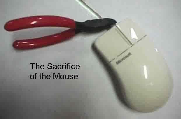
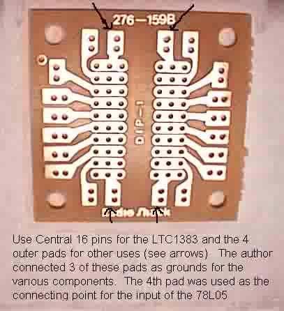
10 converter IC from pins 11 and 12 and power it from the same 5 volt source. Please let me know if you are successful. Theory of Operation The ICOM CT-17 RS232 computer level converter is both costly and requires external power. By using a cheap, readily available ultra low power TTL to RS232 converter IC, the Linear LTC1383, one can make a self-contained unit, which derives its power from the serial port itself. Although the IBM PC serial port was designed without a DC power pin, early mouse designers figured out a way to squeeze some low-current DC power from RTS or DTR lines (or from BOTH in the case of the design shown above). The LTC1383 draws only about 220uA at 5 volts - far less than most mouse circuitry. The above circuit should work with just about any serial port, including some otherwise finicky PC laptop ports. The LTC 1383 IC does all the work and requires only 4 capacitors to charge the internal pump circuits. Although one can use tiny 0.1uf non-polarized caps for the 4 charge caps, I chose some 0.47uf miniature polarized radial electrolytics to be extra sure of speedy response times in the heat of DX. All parts are available at the time of this writing online from RadioShack.com, but might be hard to find at the retail stores. I have no affiliation to Radio Shack, but enjoy their excellent website and variety of fairly cheap parts. I chose to use some pre-punched general purpose DIP circuit board, a 16-pin DIP socket, 4 standoffs, 2 grommets and a tiny aluminum case to wire the circuit - which would add about $6 to the cost. Anal-retentive hams can etch and drill their own circuit boards! I'm sure some industrious hams will figure out a way to package the whole circuit inside a DB9 shell! Instead of purchasing a DB9 female connector, I pilfered the connector and cable from an old broken Microsoft serial mouse. I not only got a "free" DB9 connector, but I found that the 4 conductor shielded cable used by the mouse already had my 5 connections made to the right pins! I even used a couple of feet of the same cable (after cutting off the 3 unused leads) as a single conductor shielded cable to run from the aluminum box to the 1/8 inch miniature phone plug for my IC-746. One builder found that he had a short in his mouse cable, so definitely test it thoroughly before using my mouse suggestion. If the thought of harming an innocent mouse is too hard to take, buy a db9 female and plastic or metal shell. IMPORTANT: If you want to use a DB25 serial connector instead, remember that the ground pin is 7, DTR is pin 20, RTS is pin 4, TxD is pin 2 and RxD is pin 3! This would certainly give you more room in the casing to house the circuitry if you decide to go that route.
11 A note about the ferrite beads. Order two of part number I received 2 packs of 25 beads and wasted $0.25. But others have only received 2 beads and were happy that they ordered quantity "2"! So life is like a box of chocolates. You won't know what you get till you open the Radio Shack box. Questions, comments, photos of your creations, etc. are welcome to groveman@cox.net. Although I built a working unit from these instructions, I make no claims or warranties about the suitability or correctness of these circuits or recommendations. I am not an engineer and I don't play one on TV. Copyright, 2000, Howard Groveman KD6UU
Constructing Two Computer to Rig Interfaces for ICOM, Ten-Tec and Yaesu Radios
 For the West Somerset Amateur Radio Club Constructing Two Computer to Rig Interfaces for ICOM, Ten-Tec and Yaesu Radios by Bas Helman G4TIC Introduction The following two circuits are both based on the
RIGblaster Plug & Play
 RIGblaster Plug & Play www.westmountainradio.com 1020 Spring City Drive Waukesha, WI 53186 262-522-6503 sales@westmountainradio.com 2013 West Mountain Radio, All rights reserved. All trademarks are the
by illumicon OptoCAT Mk2 Pietershoek XA Veldhoven The Netherlands fax
 by illumicon www.ezkits.eu OptoCAT Mk2 Pietershoek 3 5503XA Veldhoven The Netherlands fax +31-40-2230020 Contents Introduction...3 Design Considerations...3 Soldering Tips...3 Assembly...4 Option 1...5
TH E FI N EST I N G E E K E NTE RTAI N M E NT
 HACKING the C a b l e M o d e m W h at c a b l e c o m pa n i e s d o n t wa n t yo u t o k n o w DerEngel BUILDING A CONSOLE CABLE The device shown in Figure 17-1 is an RS-232 to TTL converter board,
Microsystems. SCI-6 Sound Card Interface Kit Version 1.09 January 2015
 UM Unified Microsystems SCI-6 Sound Card Interface Kit Version 1.09 January 2015 The SCI-6 interface was designed to be a low cost, high quality interface between your PC s sound card and radio transceiver.
Installation instructions for USB cables SiLabs CP2102 chipset Please install driver before connecting cable!
 TechnoFix UK Installation instructions for USB cables SiLabs CP2102 chipset This document contains four sections: 1. USB cable driver installation instructions 2. Instructions for CAT & CI-V cables 3.
Visual set-up guide. V17 Ed Durrant DD5LP 11th. Aug 2017
 Visual set-up guide V17 Ed Durrant DD5LP 11th. Aug 2017 This short visual guide is for those wishing to set-up remote control of their IC-7300 using ICOM's RS-BA1 software. RS-BA1 will work either via
CATbox a Modular Computer Interface
 CATbox a Modular Computer Interface by Bas Helman G4TIC Introduction CATbox is a modular computer aided transceiver (CAT) interface system comprising four standalone matrix board cards. One, or at most
WinKey V6 PCB Assembly Guide Version /4/2013
 WinKey V6 PCB Assembly uide Version.4 2/4/203 This document describes the assembly, checkout, and hook up of the KEL Winkey2 Serial Kit with a version V6 PCB. This design is powered directly off the PC
Universal Keying Adapter 3+
 Universal Keying Adapter 3+ The Universal Keying Adapter Version 3+ kit will allow you to key nearly any transmitter or transceiver with a straight key, electronic keyer, computer serial or parallel port
ES-362U PRESETTABLE MASTER TIMER
 142 SIERRA ST., EL SEGUNDO, CA 90245 USA (310)322-2136 FAX (310)322-8127 www.ese-web.com ES-362U PRESETTABLE MASTER TIMER OPERATION AND MAINTENANCE MANUAL The ES-362U is a four digit, presettable 100 minute
A Homebrew AUX-7 Board for the Drake TR7 and R7
 Overview A Homebrew AUX-7 Board for the Drake TR7 and R7 OK, so you don't really need an AUX-7 board to be able to transmit and receive on all frequencies with the TR7. But, there are some advantages to
TKEY-1. CW touch key. (no electromechanical contacts) Assembly manual. Last update: June 20,
 Assembly manual. Last update: June 20,") TKEY-1 CW touch key (no electromechanical contacts) Assembly manual Last update: June 20, 2017 ea3gcy@gmail.com Updates and news at: www.ea3gcy.com Thanks for constructing the TKEY-1A CW touch key Have
TKEY-1 CW touch key (no electromechanical contacts) Assembly manual Last update: June 20, 2017 ea3gcy@gmail.com Updates and news at: www.ea3gcy.com Thanks for constructing the TKEY-1A CW touch key Have
MixW RigExpert Tiny. CAT+PTT/CW Version 1.3. User s manual IMPORTANT:
 MixW RigExpert Tiny CAT+PTT/CW Version 1.3 User s manual IMPORTANT: Read this manual carefully before attempting to use the MixW RigExpert Tiny device. Table of contents Description... 3 Specifications...
ISOTERM-MULTICON USB
 ISOTERM-MULTICON USB INSTRUCTIONS FOR CP-2102 Model DATA INTERFACE de G3LIV JULY 2012 Email Johnny@melvin.com Tel 0191-2843028 www.g3liv.co.uk 1 Welcome to the World of PSK-31. l want to make it easy for
MICRO-TRAK 300 MANUAL VER 1.4
 MICRO-TRAK 300 MANUAL VER 1.4 The Micro-Trak 300 Version 1.4 is a miniature APRS (Automatic Position Reporting System) transmitter operating on the North American APRS frequency standard of 144.390 MHz.
TRAKIT-25P. Printings. Version 1.00: 10/03/01 Version 2.00: 01/20/03 Version 2.10: 01/19/04
 TRAKIT-25P Printings Version 1.00: 10/03/01 Version 2.00: 01/20/03 Version 2.10: 01/19/04 TABLE OF CONTENTS SPECIFICATIONS... 1 1.0 GENERAL DESCRIPTION... 2 1.1 Description... 2 1.2 Capabilities and Features...
Manual Main PCB Small-MIDI 4
 Index PARTLIST MAIN PCB... 2 INTRODUCTION... 3 GENERAL... 3 THE CIRCUIT... 3 ASSEMBLY KIT... 4 ASSEMBLY OF THE PCB... 4 An important tip...... 4 ASSEMBLY... 4 THE CONNECTORS... 4 Power supply J1... 4 IDC
Installation/assembly manual for DCC/Power shield
 Installation/assembly manual for DCC/Power shield The DCC circuit consists of the following components: R1/R6 R2/R3 R4/R5 D1 C2 2 kω resistor ½ Watt (colour code Red/Black/Black/Brown/Brown) 10 kω resistor
Voice Keyer Kit by DH8BQA (BX-184)
") Voice Keyer Kit by DH8BQA (BX-184) 2011 5 24 1 Quick assembly guide Most amateur radios do not have an internal voice memory for transmitting. If you want to use such a convenient feature you can build
Voice Keyer Kit by DH8BQA (BX-184) 2011 5 24 1 Quick assembly guide Most amateur radios do not have an internal voice memory for transmitting. If you want to use such a convenient feature you can build
Sierra Radio Systems. HamStack. Project Board Reference Manual V1.0
 Sierra Radio Systems HamStack Project Board Reference Manual V1.0 Welcome HamStack Project Board Reference Manual Revision 1.0.3 2011 George Zafiropoulos, KJ6VU and John Best, KJ6K This guide provides
AUDIO AMPLIFIER PROJECT
 Intro to Electronics 110 - Audio Amplifier Project AUDIO AMPLIFIER PROJECT In this project, you will learn how to master a device by studying all the parts and building it with a partner. Our test subject:
Rapid28iXL PIC Prototyping PCB User Manual
 Description Features This is a PCB designed to facilitate the rapid prototyping of a device based on a 28 pin Microchip PIC microcontroller. To allow users to focus on their application, we take care of
Sprinkler Controller Assembly Manual
 Sprinkler Controller Assembly Manual V1.0 Doug Jackson VK1ZDJ September 2010 Licence The Sprinkler Controller Design, PCB layout, Manual, and Firmware is Copyright 2010, by Douglas Jackson, VK1ZDJ. This
Moxa TCC-100 Series User s Guide
 Moxa TCC-100 Series User s Guide Eighth Edition, February 2009 www.moxa.com/product 2009 Moxa Inc. All rights reserved. Reproduction without permission is prohibited. Moxa TCC-100 Series User s Guide The
Supplement for module D061 incl. ATMega128 Prozessor
 Supplement for module D061 incl. ATMega128 Prozessor V 1.3 16. March 2006 2006 by Peter Küsters This document is in copyright protected. It is not permitted to change any part of it. It is not permitted
Select a Data Communication Interface
 Printer Setup and Operation Select a Data Communication Interface Select a Data Communication Interface You may connect your print engine to a computer using one or more of the available connections. The
ADAM-4510 RS-422/RS-485 Repeater ADAM-4510S Isolated RS-422/485 Repeater ADAM-4520 Isolated RS-422/485 Converter Startup Manual
 ADAM-510 RS-/RS-85 Repeater ADAM-510S Isolated RS-/85 Repeater ADAM-50 Isolated RS-/85 Converter Startup Manual Packing List Before you begin installing your module, please make sure that the following
Moxa TCC-100 Series Hardware Installation Guide
 Moxa TCC-100 Series Hardware Installation Guide Twelfth Edition, January 2015 www.moxa.com/product 2015 Moxa Inc. All rights reserved. P/N: 1802001000319 Moxa TCC-100 Series Hardware Installation Guide
Rapid40iXL PIC Prototyping PCB User Manual
 Description This is a PCB designed to facilitate the rapid prototyping of a device based on a 40 pin Microchip PIC microcontroller. To allow users to focus on their application, we take care of key housekeeping
K8+ Single Chip Keyer Manual August 13, 1998 Steven T. Elliott - K1EL
 Introduction K8+ Single Chip Keyer Manual August 13, 1998 Steven T. Elliott - K1EL This manual will describe the operation of the K8+ Keyer which is a low cost automatic Morse keyer designed by Steve,
Number Name Description Notes Image 0101 Resistor, 100 ohm. brown-black-browngold. ¼ watt, 5% tolerance, red-red-brown-gold. brown-black-red-gold.
 Passive Components 0101 Resistor, 100 brown-black-browngold. 690620 0102 Resistor, 220 red-red-brown-gold. 690700 0103 Resistor, 1000 brown-black-red-gold. 690865 0104 Resistor, 10k 0201 Capacitor, 1 µf,
Antenna Rotator System
 Antenna Rotator System Setup & Hardware Reference Manual May/2002 Rev 2.1c Introduction Thank you for purchasing the ARS interface. ARS is the most powerful, high performance and low cost universal rotator
MAIN PCB (The small one)
") THANKS FOR CHOOSING ONE OF OUR KITS! This manual has been written taking into account the common issues that we often find people experience in our workshops. The order in which the components are placed
THANKS FOR CHOOSING ONE OF OUR KITS! This manual has been written taking into account the common issues that we often find people experience in our workshops. The order in which the components are placed
The CW Machine Hardware
 The CW Machine Hardware 2017 Ulrich H. Steinberg The CW Machine Hardware Version 2.3 1 Contents Introduction...3 Connecting the Hardware...4 The Configuration Switches...6 Power Considerations...8 Serial
Packaging the Elecraft XG2 Receiver Test Oscillator and 2T -gen 2-Tone Test Oscillator Phil Salas AD5X
 Packaging the Elecraft XG2 Receiver Test Oscillator and 2T -gen 2-Tone Test Oscillator Phil Salas AD5X My two recent test equipment additions are the Elecraft XG2 Receiver Test Oscillator, and the Elecraft
3.1 I-7560 Pin Assignment and Specifications: Introduction
 3.1 I-7560 Pin Assignment and Specifications: Introduction The I-7560 adds a Windows serial Com port via its USB connection and is compatible with new & legacy RS-232 devices. USB Plug and Play allows
Hardware Manual RM CANview
 Hardware Manual RM CANview 1998-2005 RM Michaelides Software & Elektronik GmbH Donaustraße 14 D-36043 Fulda Germany cv_hw_e.doc Table of Contents 1 Legal Regulations...3 2 About the CANview...4 3 Important
Butterfly Laser Diode Mount
 LM14S2 Butterfly Laser Diode Mount Operating Manual LM14S2 Laser On TEC Driver LD Driver THORLABS, Inc. Ph: (973) 579-7227 435 Route 206N Fax: (973) 383-8406 Newton, NJ 07860 USA www.thorlabs.com 10614-D02
NTI. KEEMUX Series. KEEMUX-P2 (2-Port PS/2 KVM Switch) INSTALLATION / USER GUIDE R NETWORK TECHNOLOGIES INCORPORATED
 INSTALLATION / USER GUIDE R NETWORK TECHNOLOGIES INCORPORATED") NTI R NETWORK TECHNOLOGIES INCORPORATED 1275 Danner Dr Aurora, OH 44202 Tel:330-562-7070 Fax:330-562-1999 www.nti1.com KEEMUX-P2 (2-Port PS/2 KVM Switch) INSTALLATION / USER GUIDE KEEMUX Series MAN049
NTI R NETWORK TECHNOLOGIES INCORPORATED 1275 Danner Dr Aurora, OH 44202 Tel:330-562-7070 Fax:330-562-1999 www.nti1.com KEEMUX-P2 (2-Port PS/2 KVM Switch) INSTALLATION / USER GUIDE KEEMUX Series MAN049
ES-562/564U COMBINATION CLOCK/TIMER
 142 SIERRA ST., EL SEGUNDO, CA 90245 USA (310)322-2136 FAX (310)322-8127 www.ese-web.com ES-562/564U COMBINATION CLOCK/TIMER OPERATION AND MAINTENANCE MANUAL The ES-562U/564U is a combination six digit
RS-232 DATA COMMUNICATIONS WITH THE TANDY COLOR COMPUTER
 By Tom Gunnison 1998 DISCLAIMER These plans and software are provided "as is" with no guarantee of fitness for the purpose either explicit or implied. I disclaim any responsibility for losses incurred
Bluetooth to RS-232&RS422/485. EX-9132B/BI Bluetooth Adapter Operation Manual
 Bluetooth to RS-232&RS422/485 EX-9132B/BI Bluetooth Adapter Operation Manual First Edition, Jun 2008 Table of Contents 1. Introduction 2 2. Package checklist 3 3. Product Specification 4 4. Product Panel
Modtronix Engineering Modular Electronic Solutions SBC28DC. Single board computer for 28 pin DIP PICs
 Modtronix Engineering Modular Electronic Solutions Single board computer for 28 pin DIP PICs Table of Contents 1 Introduction...2 2 Features...4 3 Expansion Connectors...5 3.1 Daughter Board Connectors...5
Strain Gage Measuring Amplifier GSV-3
 Strain Gage Measuring Amplifier GS-3 Tel 03302 559 282, Fax: 03302 559 141, info@me-systeme.de, www.me-systeme.de 1 Strain Gage Measuring Amplifier GS-3 Description...4 Models...5 Measurement Resolution...5
Chill Interface PCB Assembly Instructions
 ExcelValley Chill Interface PCB Waveblaster Module MIDI Interface Board Chill Limited Edition V2 Assembly Kit Standalone midi interface board for Waveblaster synthesizer modules. Suitable for most Waveblaster
ICP PANEL-TEC PEX3000 II
 ICP PANEL-TEC PEX3000 II MODBUS PORT EXPANDER INSTALLATION AND OPERATION GUIDE REVISION HISTORY Revision Date Author Comments 000 29 Aug 2008 Keira Majors Initial release. 001 16 Sep 2008 David Walker
Schematic Diagram: R2,R3,R4,R7 are ¼ Watt; R5,R6 are 220 Ohm ½ Watt (or two 470 Ohm ¼ Watt in parallel)
") Nano DDS VFO Rev_2 Assembly Manual Farrukh Zia, K2ZIA, 2016_0130 Featured in ARRL QST March 2016 Issue Nano DDS VFO is a modification of the original VFO design in Arduino Projects for Amateur Radio by
Nano DDS VFO Rev_2 Assembly Manual Farrukh Zia, K2ZIA, 2016_0130 Featured in ARRL QST March 2016 Issue Nano DDS VFO is a modification of the original VFO design in Arduino Projects for Amateur Radio by
ANC Series RS-422 Serial Communications Adapter
 Rev. B $ 5.00 ANC - 6000 Series RS-422 Serial Communications Adapter Antona Corporation, Los Angeles, CA Antona Corporation (818)783-4299 FAX (818)783-4216 1 Antona Corporation Copyright Copyright (c)
AUDIO PROCESSOR OPERATING MANUAL
 EQplus AUDIO PROCESSOR OPERATING MANUAL EQplus AUDIO PROCESSOR OPERATING MANUAL September 2004 W2IHY TECHNOLOGIES Julius D. Jones 19 Vanessa Lane Staatsburg, N.Y. (12580) (845) 889-4253 E-mail: Julius@W2IHY.COM
Blue Point Engineering
 Blue Point Engineering Board - Pro Module (E) Instruction Pointing the Way to Solutions! Controller I Version 2.1 The Board Pro E Module provides the following features: Up to 4 minutes recording time
EAS MINI DAQ. INT of JP4 is for internal power from PC EXT of JP4 is for external power - needed for low power laptops
 EAS MINI DAQ Intro EAS MINI DAQ is an 8 channel, 12bit analog to digital converter for the IBM PC, with 4 digital input channels and 7 digital output channels. It connects to the parallel port of your
Phi-panel backpack assembly and keypad options Dr. John Liu 12/16/2012
 Phi-panel backpack assembly and keypad options Dr. John Liu 12/16/2012 1. Introduction:... 3 Currently available:... 3 2. Backpack assembly... 4 3. Connecting to a keypad... 6 4. Rotary encoder keypads...
PIEXX TS-930SE Enhanced Microprocessor Board
 PIEXX TS-930SE Enhanced Microprocessor Board PIEXX, Inc. XXX, New Hampshire www.conknet.com/piexx e-mail: c_sieg@conknet.com Phone: Introduction This user manual will tell you everything you need to know
Revised: Page 1
 Brought To You By And Designed By: Revised: 2017-05-07 Page 1 Features Of The Universal PSU Kit: Fits all standard Apple II and /// Power Supply Enclosures. (all parts included, user supplies household
Building the RGBW LED Controller
 Building the RGBW LED Controller A guide for the assembly and operation of your RGBW LED Controller. ver 3.1 Getting Started Parts list - You should have received the following parts: (1) Circuit Board,
A brief user guide Universal Learning Remote Controller
 A brief user guide Universal Learning Remote Controller Program from a PC: 1. Construct a programming cable with a DB-9 female connector. Locate pad J1 from the Universal Learning Remote Controller (ULRC)
SLCD1-IC Serial LCD Processor
 SLCD1-IC Serial LCD Processor Diagram 1: LCD Pin 13 LCD Pin 14 1 2 18 17 LCD Pin 12 LCD Pin 11 N/C 3 16 8 MHz Osc DC 4 15 8 MHz Osc Ground 5 14 DC Serial Input True/Inverted 6 7 13 12 LCD Pin 6 LCD Pin
Make Kits and Casemods
 Make Kits and Casemods This weekend, you ll learn how to make a Minty Boost usb charger and a Daisy mp3 player. After you put these together you can put them into customized cases. I made my charger fit
Connecting LEDs to the ADB I/O
 Application Note AN-2 By Magnus Pettersson September 26 1996 Connecting LEDs to the I/O Introduction The following notes are for those of you who are a bit inexperienced with hardware components. This
USER MANUAL MODEL 2017P MODEL 2017P60. RS-232 to 20mA and. RS-232 to 60mA Current Loop Converters
 USER MANUAL MODEL 2017P RS-232 to 20mA and MODEL 2017P60 RS-232 to 60mA Current Loop Converters 07M2017P-E Doc# 073051UE Revised 5/7/96 SALES OFFICE (301) 975-1000 TECHNICAL SUPPORT (301) 975-1007 1.0
The CW Machine Hardware
 The CW Machine Hardware 2010 Ulrich H. Steinberg Contents Introduction...2 Connecting the Hardware...3 The Configuration Switches...5 Power Considerations...7 Serial Communication...8 Installing the USB-Serial
RFID: Read and Display V2010. Version 1.1. Sept Cytron Technologies Sdn. Bhd.
 PR8-B RFID: Read and Display V2010 Version 1.1 Sept 2010 Cytron Technologies Sdn. Bhd. Information contained in this publication regarding device applications and the like is intended through suggestion
K8099 NIXIE CLOCK. * optional enclosure TKOK19 (black) - TKOK17 (white) ** optional plexiglass enlcosure B8099 ILLUSTRATED ASSEMBLY MANUAL
 - TKOK17 (white) ** optional plexiglass enlcosure B8099 ILLUSTRATED ASSEMBLY MANUAL") Total solder points: 230 + 74 Difficulty level: beginner 1 2 3 4 5 advanced NIXIE CLOCK K8099 ** * A unique combination of both vintage and modern electronics ILLUSTRATED ASSEMBLY MANUAL H8099IP-1 * optional
Total solder points: 230 + 74 Difficulty level: beginner 1 2 3 4 5 advanced NIXIE CLOCK K8099 ** * A unique combination of both vintage and modern electronics ILLUSTRATED ASSEMBLY MANUAL H8099IP-1 * optional
Storage Card Interface Kit
 Storage Card Interface Kit for MultiMediaCards(MMC) and Secure Digital Cards (SD) MMSD3K The MMSD3K is complete development kit interfaced to a SD or MMC card. This board ideal for projects that involve
HARDWARE OPERATIONS MANUAL
 HARDWARE OPERATIONS MANUAL Table of Contents INTRODUCTION... 2 SECTION 1: HARDWARE COMPONENT ASSEMBLIES... 2 MECHANICAL HARDWARE AND CASE... 2 PCB ASSEMBLY... 4 ISD RECORDING CIRCUIT... 5 BREADBOARD ASSEMBLY...
Speech Articulator. Model MFJ-653 INSTRUCTION MANUAL. CAUTION: Read All Instructions Before Operating Equipment 2003 MFJ ENTERPRISES, INC.
 Speech Articulator Model MFJ-653 INSTRUCTION MANUAL CAUTION: Read All Instructions Before Operating Equipment MFJ ENTERPRISES, INC. 300 Industrial Park Road Starkville, MS 39759 USA Tel: 662-323-5869 Fax:
Step 1 - Modifying the power-supply from 12 to 16 Volts Increasing the power-supply voltage to 16V increases the headroom and reduces distortion. Also
 Dada Electronics - Quad 33 Revision - Illustrated Guidelines V 2.4 First of all, thanks for your purchase of our upgrade kit! Hereunder, you will find the step-by-step guidelines for upgrading the Quad
How Computer Mice Work
 How Computer Mice Work Inside this Article 1. Introduction to How Computer Mice Work 2. Evolution of the Computer Mouse 3. Inside a Mouse 4. Connecting Computer Mice 5. Optical Mice 6. Optical Mouse Accuracy
ipod Mini Installation -=- Long but hopefully helpful -=-
 ipod Mini Installation -=- Long but hopefully helpful -=- ** Disclaimer: INFORMATION ONLY. Not responsible for damage caused to your vehicle by following the same procedure. My electronic and fabrication
Manual Industry Interfaces
 Manual Industry Interfaces W&T Release. Type 0, 0 0, 00 0, 0 0, 0 Industry Interfaces 0/0 by Wiesemann & Theis GmbH Subject to errors and changes: Since we can make mistakes, none of our statements should
CONTROL PROTOCOL Motorized Projection Screens
 CONTROL PROTOCOL Motorized Projection Screens Table of Contents Overview... 3 Control Wiring Diagram... 3 IR Control... 4 Remote Button IR Hex Commands... 4 12 Volt DC Trigger... 5 Contact Closure and
Storage Card Interface Kit
 Storage Card Interface Kit for MultiMediaCards(MMC) and Secure Digital Cards (SD) MMSD3F The MMSD3K is complete development kit interfaced to a SD or MMC card. This board ideal for projects that involve
4.3 Digital Communication
 Data Acquisition & Computer Control 11 4.3 Digital Communication Why digital communication (often termed digital input/output, or DIO)? Because the language of computers (and many peripheral devices) is
Bluetooth TO Serial CONVERTER E-P132-B
 Bluetooth TO Serial CONVERTER E-P132-B 1 Table of Contents Introduction..3 Package checklist...4 Product Specification...5 Product Panel Views Description...6 Product Views. 6 DC-In Power Outlet 6 Antenna
Media Converters. Media Converters. Product Selection Guides
 Product Selection Guides Media Converters Serial-to-Fiber Converter Selection Guide....................................-2 Serial-to-Serial Converter Selection Guide...................................-3
CDN502 HIGH DENSITY I/O ADAPTER USER GUIDE
 CDN502 HIGH DENSITY I/O ADAPTER USER GUIDE 13050201 (c) Copyright DIP Inc., 1996 DIP Inc. P.O. Box 9550 MORENO VALLEY, CA 92303 714-924-1730 CONTENTS DN502 PRODUCT OVERVIEW 1 DN502 INSTALLATION 1 POWER
Building the FlipChip Tester
 Building the FlipChip Tester 1. Assembly of the Core Board You will need a fine low-wattage soldering iron and a Voltmeter. Take your time to solder the components on the Core Board. Better to spend a
Building and using JasperMIDI
 Building and using JasperMIDI Table of Contents Introduction... Bill Of Materials... 2 Building Choices... 3 Construction... 4 Installing in a Jasper enclosure... 5 Standalone use... 6 Using JasperMIDI...
Technical Specifications
 Technical Specifications ACF30 Floppy Bay Smart Card Reader Advanced Card Systems Ltd. Website: www.acs.com.hk Email: info@acs.com.hk Table of Contents 1.0. Introduction... 3 2.0. Features... 4 3.0. Supported
Supplement for module D041 incl. ATMega8 Prozessor
 Supplement for module D041 incl. ATMega8 Prozessor V 1.4 16. March 2006 2006 by Peter Küsters This document is in copyright protected. It is not permitted to change any part of it. It is not permitted
Building Morpheus v1.00a
 Building Morpheus v1.00a Version 0.95 Copyright 2009 by William Henning Updated documentation will always be available at Morpheus v0.1 in mid-2008 1 Table of Contents Introduction...4 Top of board:...4
AAZ-0914A USB, Blue tooth and Graphic CPU 50MHZ Antenna Analyzer
 Fox Delta Amateur Radio Projects & Kits FD- AAZ-0914A AAZ-0914A USB, Blue tooth and Graphic CPU 50MHZ Antenna Analyzer AAZ- 0914A KIT: USB Standalone, Blue tooth standalone and Graphic CPU capable 50MHZ*
Product Manual. USB BAY-4 Port Serial DB- 9 RS-232 Adapter with FTDI Chipset. Coolgear, Inc. Version 1.1 September 2017 Model Number: USBG-BAY4
 USB BAY-4 Port Serial DB- 9 RS-232 Adapter with FTDI Chipset Product Manual Coolgear, Inc. Version 1.1 September 2017 Model Number: USBG-BAY4 2 USBG-BAY4 Product Manual Revision History Revision Date Author
UTS485 & ULOG485 USB Converter Owner's Manaul
 UTS485 & ULOG485 USB Converter Owner's Manaul UTS485-002 CONTENTS Chapter 1. Introduction 1-1 Introduction...1 Chapter 2. System Setup 2-1 Introduction...2 2-2 RS422/RS485 interface setting...2 2-3 Installation
MPA FLASH PROGRAMMING
 LBI-38982 Mobile Communications MPA FLASH PROGRAMMING Programming Instructions TABLE OF CONTENTS INTRODUCTION...3 INSTALLATION...3 PC REQUIREMENTS...3 MAKING BACKUPS...3 SYSTEM HOOK-UP...4 MPA Radio...4
CDN503 HIGH DENSITY I/O ADAPTER USER GUIDE
 CDN503 HIGH DENSITY I/O ADAPTER USER GUIDE 13050301 (c) Copyright DIP Inc., 1996 DIP Inc. P.O. Box 9550 MORENO VALLEY, CA 92303 714-924-1730 CONTENTS DN503 PRODUCT OVERVIEW 1 DN503 INSTALLATION 1 POWER
GLiPIC Ver C Assembly manual Ver 1.0
 GLiPIC Ver C Assembly manual Ver 1.0 Last Rev 1.1 Oct 30, 2001 Author: Ranjit Diol Disclaimer and Terms of Agreement As with any kit, only the individual parts supplied are guaranteed against defects and
Bluetooth to RS-232 Converter. RT-132B Bluetooth Adaptor Operation Manual
 Bluetooth to RS-232 Converter RT-132B Bluetooth Adaptor Operation Manual First Edition, Nov 2007 Table of Contents 1. Introduction.. 2 2. Package checklist.. 3 3. Product Specification... 4 4. Product
RC Tractor Guy Controller V2.1 Assembly Guide
 RC Tractor Guy Controller V. Assembly Guide Features 0 Push button inputs Dual axis thumb sticks with built-in push button Rotary encoders with built-in push button MCU Socket to suit Meduino Mega 560
Four opto-isolated signal channels: SD, RD, RTS, and CTS. Electrical compatibility with RS-485. A 5V DC/DC converter for power isolation
 July 2000 RS-4 Port Isolator IC0ACC03 The IC0ACC03 RS-4 Port Isolator replaces the obsolete ICCMM0 Isolated Repeater/Converter (also known as the Brick ). This Port Isolator provides the basic functionality
Step 1 The tools & the Components The tools you need: A good quality soldering iron with a fine point (max 30) Watt or a soldering-station. A desolder
 Watt or a soldering-station. A desolder") Upgrade/revision manual Quad 44 pre amplifier. V2.5 These are the illustrated step-by-step guidelines for upgrading your Quad 44 with the Dada Electronics upgrade-kits. The Quad 44 preamp was the first
Upgrade/revision manual Quad 44 pre amplifier. V2.5 These are the illustrated step-by-step guidelines for upgrading your Quad 44 with the Dada Electronics upgrade-kits. The Quad 44 preamp was the first
Integrity Instruments Application Notes. Release 1
 Integrity Instruments Application Notes Release 1 What is EIA/TIA/RS-485 What is EIA/TIA/RS-422 Half Duplex and Full Duplex Communication Asynchronous Communicatin Grounding EIA/TIA/RS-485/422 Shielding
ARDUINO MEGA 2560 REV3 Code: A000067
 ARDUINO MEGA 2560 REV3 Code: A000067 The MEGA 2560 is designed for more complex projects. With 54 digital I/O pins, 16 analog inputs and a larger space for your sketch it is the recommended board for 3D
Manual Fiber Optic Interfaces
 Manual Fiber Optic Interfaces Type 81210, 81211 61210, 61211 65210, 65211 41210 Release 1.4 Subject to error and alteration 31 06/2007 by Wiesemann & Theis GmbH Subject to error and alteration: Since it
DIABLOSPORT PREDATOR REVISION UPDATE INSTRUCTIONS
 DIABLOSPORT PREDATOR REVISION UPDATE INSTRUCTIONS This page contains instructions that will guide you through the process of updating the DiabloSport Predator to the latest software revision available.
USER MANUAL. MODEL 2011 High Speed Asynchronous to Synchronous Converter
 USER MANUAL MODEL 011 High Speed Asynchronous to Synchronous Converter Part# 07M011-A Doc# 0601UA Revised 03/16/94 SALES ICE (301) 975-1000 TECHNICAL SUPPORT (301) 975-1007 http://www.patton.com 1.0 WARRANTY
Uzebox Kit Assembly Guide
 Uzebox Kit Assembly Guide V1.3 Page 1 of 18 Revision History Version Date Author Description 1.0 01-Nov-2012 A.Bourque Initial release 1.1 6-Nov-2012 A.Bourque Minor corrections 1.2 28-Jan-2014 A.Bourque
Vorne Industries. Model 77/232 Serial Input Numeric 3" Display User's Manual
 Vorne Industries Model 77/232 Serial Input Numeric 3" Display User's Manual 1445 Industrial Drive Itasca, IL 60143-1849 (630) 875-3600 Telefax (630) 875-3609 Page 2 Model 77/232 Serial Input Numeric 3"
KK1L 2x6 Antenna Switch Relay Controller / Dual Band Decoder Basic Assembly Version 4.8 (new 24-Aug-2009) Parts List updated 19-AUG-2016
 Parts List updated 19-AUG-2016") KK1L 2x6 Antenna Switch Relay Controller / Dual Band Decoder Basic Assembly Version 4.8 (new 24-Aug-2009) Parts List updated 19-AUG-2016 Ronald Rossi, KK1L http://home.comcast.net/~kk1l Design Features:
KK1L 2x6 Antenna Switch Relay Controller / Dual Band Decoder Basic Assembly Version 4.8 (new 24-Aug-2009) Parts List updated 19-AUG-2016 Ronald Rossi, KK1L http://home.comcast.net/~kk1l Design Features: