MOD-IO development board Users Manual
|
|
|
- Sherilyn Hampton
- 6 years ago
- Views:
Transcription


 0, OLIMEX")
1 MOD-IO development board Users Manual All boards produced by Olimex are ROHS compliant Rev. B, September 0 Copyright(c) 0, OLIMEX Ltd, All rights reserved Page
2 INTRODUCTION MOD-IO is a small but powerful development board who let you control optoisolated input and relay outputs - with this features is possible to turn on and off almost any electronic device at home. The board has UEXT_FEMALE connector which allows you to communicate with a PC and UEXT_MALE connector where you can connect other Olimex board with UEXT. The main idea of MOD-IO chain connection is to extend: - isolated relay outputs - isolated digit inputs - non isolated analog inputs - non isolated digit inputs/outputs using UEXT male/female connector. So the MCU interfaces (IC, SPI, UART) from all chain boards are connected in parallel. Note that if you want to connect more than MOD-IO board then on the interface bus (IC or UART or SPI) has to have only one Master device. The other devices have to be Slaves. For example: if UART interface is used - the master will send a string with Slave address and command. All Slaves will listen UART bus through RXD line while all Slave TXD lines are inputs. So when the address is recognized from the Slave device, the one will answer as it will force TXD pin like output but immediately after command answer is finished the Slave TXD pin must be initialized like input. The same principle can be used for other interfaces (SPI or IC). BOARD FEATURES Microcontroller: AtmegaL AVRISP connector JTAG connector EXT connector UEXT_MALE UEXT_FEMALE Clock circuit User button Reset circuit and button Power Jack Power-on led Nine status leds Four optocoupler isolated inputs Four Relays PCB: FR-,. mm (0,0"), solder mask, silkscreen component print Dimensions: 00x0 mm (.x.") Page
3 ELECTROSTATIC WARNING The MOD-IO board is shipped in protective anti-static packaging. The board must not be subject to high electrostatic potentials. General practice for working with static sensitive devices should be applied when working with this board. BOARD USE REQUIREMENTS Cables: Hardware: Software: The cable you will need depends on the programmer/debugger you use. If you use AVR-PG, or AVR-JTAG, you will need RS cable, if you use AVR-PG, you will need LPT cable, if you use AVR-USBJTAG, AVR-ISP00, AVR-ISP00-TINY, or AVR-ISP00-ISO, you will need. meter A-B USB cable. One of Olimex programmers/debuggers AVR-PG, AVR-PG, AVR-ISP00, AVR-ISP00-TINY, AVR-ISP00-ISO, AVR-JTAG, AVRUSB-JTAG, or other compatible programming/debugging tool. AVR C Compiler PROCESSOR FEATURES MOD-IO use -bit AVR Microcontroller with K Bytes In-System Programmable Flash, with these features: High-performance, Low-power AVR -bit Microcontroller Advanced RISC Architecture Powerful Instructions Most Single-clock Cycle Execution x General Purpose Working Registers Fully Static Operation Up to MIPS Throughput at MHz On-chip -cycle Multiplier High Endurance Non-volatile Memory segments K Bytes of In-System Self-programmable Flash program memory Bytes EEPROM K Byte Internal SRAM Write/Erase Cycles: 0,000 Flash/00,000 EEPROM Data retention: 0 years at C/00 years at C Optional Boot Code Section with Independent Lock Bits In-System Programming by On-chip Boot Program True Read-While-Write Operation Programming Lock for Software Security JTAG (IEEE std.. Compliant) Interface Boundary-scan Capabilities According to the JTAG Standard Extensive On-chip Debug Support Page
4 Programming of Flash, EEPROM, Fuses, and Lock Bits through the JTAG Interface Peripheral Features Two -bit Timer/Counters with Separate Prescalers and Compare Modes One -bit Timer/Counter with Separate Prescaler, Compare Mode, and Capture Mode Real Time Counter with Separate Oscillator Four PWM Channels -channel, 0-bit ADC Single-ended Channels Differential Channels in TQFP Package Only Differential Channels with Programmable Gain at x, 0x, or 00x Byte-oriented Two-wire Serial Interface Programmable Serial USART Master/Slave SPI Serial Interface Programmable Watchdog Timer with Separate On-chip Oscillator On-chip Analog Comparator Special Microcontroller Features Power-on Reset and Programmable Brown-out Detection Internal Calibrated RC Oscillator External and Internal Interrupt Sources Six Sleep Modes: Idle, ADC Noise Reduction, Power-save, Power-down, Standby and Extended Standby I/O and Packages Operating Voltages. -.V Speed Grades Programmable I/O Lines 0 - MHz Power MHz, V, and C Active:. ma Idle Mode: 0. ma Power-down Mode: < µa Page
5 BLOCK DIAGRAM Page

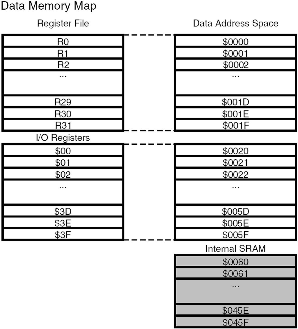
6 MEMORY MAP Page
7 Page
8 Page IN- IN R D N/SMD R 0R D N/SMD R 0R D N/SMD red LED red LED red LED red LED U U HASMD U HASMD U HASMD HASMD I I I I.K R.K R.K R0.K R I I I I 00n Q BUT TDI VCC VCC VCC A AVCC AREF XTAL XTAL RESET BH0S 0 TXD SDA MOSI #SS 00n C 00n TXD SDA MOSI #SS IDC0S/PCB 0 C UEXT_FEMALE NA R 00n 00n NA C C 0K R0.K R MCP0T.K R K R PWR_LED red VCC U RESET 00n C 00n C0 C p C p C 00n C C RXD SCL MISO SCK.K R Q RST MHz/0pF NA RXD SCL MISO SCK RST 00R R 0R/% R 0R/% R T0A(x.x.mm) ATMEGAL O[..] (OC)PD (ICP)PD (OCA)PD (OCB)PD (INT)PD (INT0)PD (TXD)PD (RXD)PD0 (TOSC)PC (TOSC)PC PC(TDI) PC(TDO) PC(TMS) PC(TCK) PC(SDA) PC0(SCL) UEXT_MALE 0 0 (SCK)PB (MISO)PB (MOSI)PB (SS)PB (AIN)PB (AIN0/INT)PB (T)PB (T0)PB0 C 00n R I BUT TXD RXD TDI TDO TMS TCK SDA SCL 0 SCK MISO MOSI #SS LED I I I T0A(x.x.mm) BUT 00R.K R R 0R Hz/pF TCK TDO TMS STAT yellow R EXT WFS JTAG C RST 0 BH0S RST IN- IN- - + R 0R D N/SMD R nf AN K 0n C IN- IN- - + NA R C nf NA 0 AVRISP.K R R (ADC)PA (ADC)PA (ADC)PA (ADC)PA (ADC)PA (ADC)PA (ADC)PA (ADC0)PA0 C OUT ADJ/ IN VR() LMIMPX-ADJ R 0K K R R 0K K R O K R 0K R D N/SMD O D N/SMD O MOD-IO CO PYRIGHT(C), 00 Rev. A R 0K K R D N/SMD O D N/SMD green O T BC REL RAS-0- green O T BC REL RAS-0- green O T BC REL RAS-0- green O T BC REL RAS-0- +V IN- IN- TB/.mm 00R C R 0 AN AN AN AN O O O O 0R D N(smd) R +V +V AIN-- AIN-- 00R AN O[..] AN[..] 0k R + R nf NA AN AN 00n C 0u/0V/tant AIN-- C nf NA R C0 R0 Fmax=0kHz 00uH/SW L 0uF/V C uf/.v 00R R 00R R uf/0v C +V AIN-- TB/.mm AIN-- n FB RT SW EN BD00FSO- N.C. INV VIN VR(V) + AIN-- 0k C R + G DB0(SMD) +V YDJ- -0 VDC PWR_J R K R K R0 K R K REL REL REL REL OUT- OUT- OUT- OUT- OUT- OUT- OUT- OUT- OUT- OUT- OUT- OUT- SCHEMATIC O[..]
 and pin (XTAL). Crystal Quartz.kHz connected to AtmegaL pin ((TOSC)PC) and pin ((TOSC)PC).")
9 BOARD LAYOUT POWER SUPPLY CIRCUIT MOD-IO is typically power supplied with -0V DC. Power consumption when all relays are working is about 0 ma. CLOCK CIRCUIT Crystal Quartz MHz connected to Atmegal pin (XTAL) and pin (XTAL). Crystal Quartz.kHz connected to AtmegaL pin ((TOSC)PC) and pin ((TOSC)PC). RESET CIRCUIT MOD-IO reset circuit includes Reset scheme MCP0T (U), AVRISP connector pin, JTAG connector pin, AtmegaL pin (RESET), R (00Ohm), R0 (0k), C0 (00nF) and RST button. Page

10 CONNECTOR DESCRIPTIONS AVRISP Pin # Signal Name MOSI NC RST SCK MISO 0 Pin # Signal Name TCK TDO TMS RST NC TDI 0 Pin # Signal Name PD PD PD PD JTAG EXT Page 0

PB0")
PB signal I IN connected to")
11 UEXT_MALE Pin # Signal Name NC RXD TXD SCL SDA MISO MOSI SCK 0 #SS Pin # Signal Name NC RXD TXD SCL SDA MISO MOSI SCK 0 #SS Pin # Signal - + UEXT_FEMALE IN, IN IN, IN IN connected to (T0)PB0 signal I IN connected to (T)PB signal I IN connected to (AIN0/INT)PB signal I IN connected to (INT)PD signal I Page
PA AN (ADC)PA AIN- Pin # Signal Name Connected to AN (ADC)PA AN (ADC)PA A Analog PWR_J Pin # Signal Name Power Input JUMPER DESCRIPTION There are no jumpers on this board.")
12 OUT, OUT, OUT, OUT OUT connected to (ADC)PA signal name O OUT connected to (ADC)PA signal name O OUT connected to (ADC)PA signal name O OUT connected to (ADC0)PA0 signal name O AIN- Pin # Signal Name Connected to VCC AN (ADC)PA AN (ADC)PA AIN- Pin # Signal Name Connected to AN (ADC)PA AN (ADC)PA A Analog PWR_J Pin # Signal Name Power Input JUMPER DESCRIPTION There are no jumpers on this board. INPUT/OUTPUT User button with name BUT connected to AtmegaL pin ((INT0)PD). Reset button with name RST connected to AtmegaL pin (RESET). Status LED (yellow) with name STAT connected via R (0 Ohm) to Atmegal pin ((AIN)PB). Status LED (red) with name LED visualize input (IN) state. Status LED (red) with name LED visualize input (IN) state. Status LED (red) with name LED visualize input (IN) state. Status LED (red) with name LED visualize input (IN) state. Status LED (green) with name O visualize relay (REL) state. Status LED (green) with name O visualize relay (REL) state. Status LED (green) with name O visualize relay (REL) state. Status LED (green) with name O visualize relay (REL) state. Power-on LED (red) with name PWR_LED shows that + voltage is applied to the board. Page
13 MECHANICAL DIMENSIONS Page
14 AVAILABLE DEMO SOFTWARE MOD-IO firmware C source and HEX Page
15 ORDER CODE MOD-IO assembled and tested. How to order? You can order to us directly or by any of our distributors. Check our web for more info. Revision history: Board's revision: Manual's revision: Rev. A - create November 00 Rev. B edited September 0 added more detailed INTRODUCTION and MECHANICAL DIMENSIONS Page
16 Disclaimer 0 Olimex Ltd. All rights reserved. Olimex, logo and combinations thereof, are registered trademarks of Olimex Ltd. Other terms and product names may be trademarks of others. The information in this document is provided in connection with Olimex products. No license, express or implied or otherwise, to any intellectual property right is granted by this document or in connection with the sale of Olimex products. Neither the whole nor any part of the information contained in or the product described in this document may be adapted or reproduced in any material from except with the prior written permission of the copyright holder. The product described in this document is subject to continuous development and improvements. All particulars of the product and its use contained in this document are given by OLIMEX in good faith. However all warranties implied or expressed including but not limited to implied warranties of merchantability or fitness for purpose are excluded. This document is intended only to assist the reader in the use of the product. OLIMEX Ltd. shall not be liable for any loss or damage arising from the use of any information in this document or any error or omission in such information or any incorrect use of the product. Page
MOD-IO development board user's manual
 MOD-IO development board user's manual All boards produced by Olimex are ROHS compliant Rev. C, March 013 Copyright(c) 011, OLIMEX Ltd, All rights reserved Page 1 INTRODUCTION BOARD FEATURES MOD-IO is
AVR- M16 development board Users Manual
 AVR- M16 development board Users Manual All boards produced by Olimex are ROHS compliant Rev. C, January 2005 Copyright(c) 2009, OLIMEX Ltd, All rights reserved Page1 INTRODUCTION AVR-M16 is header board
AVR-TLCD-128CAN development board Users Manual
 AVR-TLCD-128CAN development board Users Manual Rev.A, July 2008 Copyright(c) 2008, OLIMEX Ltd, All rights reserved INTRODUCTION: AVR-TLCD-128CAN adds cool LCD and touchscreen interface to your next project.
AVR-P20 development board Users Manual
 AVR-P20 development board Users Manual All boards produced by Olimex are ROHS compliant Revision A, October 2005 Copyright(c) 2009, OLIMEX Ltd, All rights reserved Page 1 INTRODUCTION: The AVR Microcontrollers
AVR-P development board Users Manual
 AVR-P40-8515 development board Users Manual All boards produced by Olimex are ROHS compliant Revision A, January 2002 Copyright(c) 2009, OLIMEX Ltd, All rights reserved Page 1 INTRODUCTION: The AVR Microcontroller
PIC-32MX development board Users Manual
 PIC-32MX development board Users Manual All boards produced by Olimex are ROHS compliant Rev.A, June 2008 Copyright(c) 2008, OLIMEX Ltd, All rights reserved INTRODUCTION: The NEW PIC-32MX board uses the
MSP430-PG2231 development board Users Manual
 MSP430-PG3 development board Users Manual All boards produced by Olimex are ROHS compliant Revision A, June 0 Copyright(c) 0, OLIMEX Ltd, All rights reserved Page INTRODUCTION: MSP430-PG3 is prototype
Arduino Uno R3 INTRODUCTION
 Arduino Uno R3 INTRODUCTION Arduino is used for building different types of electronic circuits easily using of both a physical programmable circuit board usually microcontroller and piece of code running
MSP-RFLINK development board Users Manual
 MSP-RFLINK development board Users Manual All boards produced by Olimex are ROHS compliant Revision Initial, May 0 Copyright(c) 0, OLIMEX Ltd, All rights reserved Page INTRODUCTION: MSP-RFLINK is wireless.4
MOD-BT development board Users Manual
 MOD-BT development board Users Manual All boards produced by Olimex are ROHS compliant Rev. B, September 2009 Copyright(c) 2010, OLIMEX Ltd, All rights reserved Page 1 INTRODUCTION BOARD FEATURES MOD-BT
PIC-LCD-3310 development board Users Manual
 PIC-LCD-3310 development board Users Manual Rev.A, July 2008 Copyright(c) 2008, OLIMEX Ltd, All rights reserved INTRODUCTION: PIC-LCD-3310 is development board with PIC18F67J50, NOKIA 3310 BW 84x48 pixels
LPC-P1114 development board Users Manual
 LPC-P1114 development board Users Manual All boards produced by Olimex are ROHS compliant Revision A, May 2010 Copyright(c) 2009, OLIMEX Ltd, All rights reserved Page 1 INTRODUCTION LPC-P1114 is development
SBAT90USB162 Atmel. SBAT90USB162 Development Board User s Manual
 SBAT90USB162 Atmel AT90USB162 Development Board User s manual 1 1. INTRODUCTION Thank you for choosing the SBAT90USB162 Atmel AT90USB162 development board. This board is designed to give a quick and cost-effective
LPC-H1343 development board Users Manual
 LPC-H343 development board Users Manual All boards produced by Olimex are ROHS compliant Revision B, June 0 Copyright(c) 0, OLIMEX Ltd, All rights reserved Page INTRODUCTION LPC-H343 is header board with
MOD-MRF24J40 development board Users Manual
 MOD-MRF24J40 development board Users Manual All boards produced by Olimex are ROHS compliant Rev. Initial, May 2011 Copyright(c) 2011, OLIMEX Ltd, All rights reserved Page 1 INTRODUCTION: MOD-MRF24J40
VLSI Design Lab., Konkuk Univ. Yong Beom Cho LSI Design Lab
 AVR Training Board-I V., Konkuk Univ. Yong Beom Cho ybcho@konkuk.ac.kr What is microcontroller A microcontroller is a small, low-cost computeron-a-chip which usually includes: An 8 or 16 bit microprocessor
LPC-P1114 development board Users Manual
 LPC-P4 development board Users Manual All boards produced by Olimex are ROHS compliant Revision B, November 0 Copyright(c) 0, OLIMEX Ltd, All rights reserved Page INTRODUCTION LPC-P4 is development board
ARDUINO MEGA INTRODUCTION
 ARDUINO MEGA INTRODUCTION The Arduino MEGA 2560 is designed for projects that require more I/O llines, more sketch memory and more RAM. With 54 digital I/O pins, 16 analog inputs so it is suitable for
LBAT90USB162 Atmel. LBAT90USB162 Development Board User s Manual
 LBAT90USB162 Atmel AT90USB162 Development Board User s manual 1 1. INTRODUCTION Thank you for choosing the LBAT90USB162 Atmel AT90USB162 development board. This board is designed to give quick and cost-effective
DBAT90USB162 Atmel. DBAT90USB162 Enhanced Development Board User s Manual
 DBAT90USB162 Atmel AT90USB162 Enhanced Development Board User s manual 1 1. INTRODUCTION Thank you for choosing the DBAT90USB162 Atmel AT90USB162 enhanced development board. This board is designed to give
AVR Training Board-I. VLSI Design Lab., Konkuk Univ. LSI Design Lab
 AVR Training Board-I V., Konkuk Univ. Tae Pyeong Kim What is microcontroller A microcontroller is a small, low-cost computeron-a-chip which usually includes: An 8 or 16 bit microprocessor (CPU). A small
PIC-P40 development board Users Manual
 PIC-P40 development board Users Manual All boards produced by Olimex are ROHS compliant Rev.E, February 008 Copyright(c) 008, OLIMEX Ltd, All rights reserved Page INTRODUCTION: PIC-P40 board is development
PIC-P28-USB development board Users Manual
 PIC-P28-USB development board Users Manual Rev.A, June 2007 Copyright(c) 2007, OLIMEX Ltd, All rights reserved INTRODUCTION: PIC-P28-USB board was designed in mind to create board which to allow easy interface
AVR Board for Projects is the Most Complete Simple to use Development Board For ATmega32 Product Datasheet
 is the Most Complete Simple to use Development Board For ATmega Sr. Num. Topics Page About AVR Board for Project The AVR Board for Project Hardware Details Using AVR Board for Project 0 Important information
MOD-IO2 extension board USER S MANUAL Revision B, October 2012 Designed by OLIMEX Ltd, 2012
 MOD-IO2 extension board USER S MANUAL Revision B, October 2012 Designed by OLIMEX Ltd, 2012 All boards produced by Olimex LTD are ROHS compliant DISCLAIMER 2012 Olimex Ltd. Olimex, logo and combinations
Lecture 14. Ali Karimpour Associate Professor Ferdowsi University of Mashhad
 Lecture 14 AUTOMATIC CONTROL SYSTEMS Ali Karimpour Associate Professor Ferdowsi University of Mashhad Lecture 4 The AVR Microcontroller Introduction to AVR CISC (Complex Instruction Set Computer) Put as
LPC-P1227 development board USER S MANUAL Initial release, March 2012 Designed by OLIMEX Ltd, 2011
 LPC-P1227 development board USER S MANUAL Initial release, March 2012 Designed by OLIMEX Ltd, 2011 All boards produced by Olimex LTD are ROHS compliant Disclaimer: 2012 Olimex Ltd. Olimex, logo and combinations
MOD-ZIGBEE-PIR sensor development board USER S MANUAL All boards produced by Olimex LTD are ROHS compliant
 sensor development board USER S MANUAL All boards produced by Olimex LTD are ROHS compliant Revision B, Januray 2013 Designed by OLIMEX Ltd, 2011 Disclaimer: 2012 Olimex Ltd. Olimex, logo and combinations
MOD-RFID125-BOX User Manual
 MOD-RFID125-BOX User Manual All boards produced by Olimex are ROHS compliant Rev.B, May 2011 Copyright(c) 2011, OLIMEX Ltd, All rights reserved Page 1 INTRODUCTION: FEATURES: MOD-RFID125-BOX is an RFID
MOD-RFID125 User Manual. All boards produced by Olimex are ROHS compliant. Rev.A, February 2008 Copyright(c) 2008, OLIMEX Ltd, All rights reserved
 2008, OLIMEX Ltd, All rights reserved") MOD-RFID125 User Manual All boards produced by Olimex are ROHS compliant Rev.A, February 2008 Copyright(c) 2008, OLIMEX Ltd, All rights reserved INTRODUCTION: FEATURES: MOD-RFID125 is an RFID station,
MOD-RFID125 User Manual All boards produced by Olimex are ROHS compliant Rev.A, February 2008 Copyright(c) 2008, OLIMEX Ltd, All rights reserved INTRODUCTION: FEATURES: MOD-RFID125 is an RFID station,
PIC-P67J60 development board Users Manual
 PIC-P67J60 development board Users Manual Rev.A, July 2008 Copyright(c) 2008, OLIMEX Ltd, All rights reserved INTRODUCTION: If you want to build your own Internet enabled device this is the board for you.
3.3V regulator. JA H-bridge. Doc: page 1 of 7
 Digilent Cerebot Board Reference Manual Revision: 11/17/2005 www.digilentinc.com 215 E Main Suite D Pullman, WA 99163 (509) 334 6306 Voice and Fax Overview The Digilent Cerebot Board is a useful tool for
PIC-32MX development board User's Manual
 PIC-MX development board User's Manual All boards produced by Olimex are ROHS compliant Document revision B, April 07 Copyright(c) 008, OLIMEX Ltd, All rights reserved INTRODUCTION: The NEW PIC-MX board
LPC-P1227 development board USER S MANUAL Revision B, July 2013 Designed by OLIMEX Ltd, 2011
 LPC-P1227 development board USER S MANUAL Revision B, July 2013 Designed by OLIMEX Ltd, 2011 All boards produced by Olimex LTD are ROHS compliant Disclaimer: 2013 Olimex Ltd. Olimex, logo and combinations
MOD-RS485-ISO. Isolated extension board with RS485 interface. USER S MANUAL Revision B, October 2012 Designed by OLIMEX Ltd, 2012
 MOD-RS485-ISO Isolated extension board with RS485 interface USER S MANUAL Revision B, October 2012 Designed by OLIMEX Ltd, 2012 All boards produced by Olimex LTD are ROHS compliant DISCLAIMER 2012 Olimex
PIC-MAXI-WEB development board Users Manual
 PIC-MAXI-WEB development board Users Manual Rev.B, February 2009 Copyright(c) 2009, OLIMEX Ltd, All rights reserved INTRODUCTION: This board allows you to easily develop Ethernet connectivity applications.
LPC-E2468 development board Users Manual
 LPCE2468 development board Users Manual Rev.B, February 2008 Copyright(c) 2008, OLIMEX Ltd, All rights reserved INTRODUCTION: LPCE2468 uc Linux development prototype board with LPC2468 USB, Ethernet, SD/MMC
Various power connectors. 3.3V regulator. 64K Flash (Internal) 2K EEPROM (Internal) 4K SRAM (Internal) JA Mem Adr/ Data. Doc: page 1 of 9
 2K EEPROM (Internal) 4K SRAM (Internal) JA Mem Adr/ Data. Doc: page 1 of 9") Cerebot II Board Reference Manual Revision: September 14, 2007 Note: This document applies to REV B of the board. www.digilentinc.com 215 E Main Suite D Pullman, WA 99163 (509) 334 6306 Voice and Fax Overview
Cerebot II Board Reference Manual Revision: September 14, 2007 Note: This document applies to REV B of the board. www.digilentinc.com 215 E Main Suite D Pullman, WA 99163 (509) 334 6306 Voice and Fax Overview
PIC-IO development board User's Manual
 PIC-IO development board User's Manual Rev.C, October 0 Copyright(c) 0, OLIMEX Ltd, All rights reserved All boards produced by Olimex are ROHS compliant INTRODUCTION: PIC-IO board was designed as simple
MSP430-EasyWeb3 development board Users Manual
 MSP0-EasyWeb development board Users Manual Page INTRODUCTION: MSP0-EasyWeb is TCP/IP board with MPS0F9 based on Andreas Dannenberg easyweb TCP/IP. On the board, there are JTAG connector, two extension
UM2461 User manual. SPC584B-DIS Discovery Board. Introduction
 User manual SPC584B-DIS Discovery Board Introduction The SPC584B-DIS is a low-cost development board to evaluate and develop applications with the microcontroller SPC584B70E1 in etqfp 64-pin package. This
LPC-MT-2138 development board Users Manual
 LPC-MT-8 development board Users Manual All boards produced by Olimex are ROHS compliant Rev. Initial, September 00 Copyright(c) 00, OLIMEX Ltd, All rights reserved Page INTRODUCTION LPC-MT-8 is small
LAMPIRAN. Universitas Sumatera Utara
 LAMPIRAN 35 Features 2. High-performance, Low-power AVR 8-bit Microcontroller 3. Advanced RISC Architecture 131 Powerful Instructions Most Single-clock Cycle Execution 32 x 8 General Purpose Working Registers
APPLICATION NOTE. AT11008: Migration from ATxmega16D4/32D4 Revision E to Revision I. Atmel AVR XMEGA. Introduction. Features
 APPLICATION NOTE AT11008: Migration from ATxmega16D4/32D4 Revision E to Revision I Atmel AVR XMEGA Introduction This application note lists out the differences and changes between Revision E and Revision
MOD-RS485-ISO. Isolated extension board with RS485 interface. USER S MANUAL Document revision C, April 2017 Designed by OLIMEX Ltd, 2017
 MODRS485ISO Isolated extension board with RS485 interface USER S MANUAL Document revision C, April 2017 Designed by OLIMEX Ltd, 2017 All boards produced by Olimex LTD are ROHS compliant DISCLAIMER 2017
An Arduino Controlled 1 Hz to 60 MHz Signal Generator
 An Arduino Controlled 1 Hz to 60 MHz Signal Generator Greg McIntire, AA5C AA5C@arrl.net WWW..ORG 1 Objectives Build a standalone 60 MHz signal generator based on the DDS-60 board. Originally controlled
U4DIL. AVR USB Module. Rev. 1.1 Documentation Rev. 19. Reusch Elektronik Reusch Elektronik, Dipl.-Ing. (FH) Rainer Reusch
 Rainer Reusch") AVR USB Module Documentation Rev. 19 2010, Dipl.-Ing. (FH) Rainer Reusch www.reusch-elektronik.de http://products.reworld.eu/u4dil.htm File: _Manual Created: 2010-02-10 Changed: 2010-09-07 Contents 1.
AVR USB Module Documentation Rev. 19 2010, Dipl.-Ing. (FH) Rainer Reusch www.reusch-elektronik.de http://products.reworld.eu/u4dil.htm File: _Manual Created: 2010-02-10 Changed: 2010-09-07 Contents 1.
MT-T34 User Guide January 13,
 MT-T34 1 Table of Contents Overview...3 Introduction... 3 Board Features... 4 ATtiny1634 Features... 5 Hardware...6 Top View / Pinout... 6 Header Pins (power)... 6 Header Pins (signal)... 7 Solder Jumpers...
User Manual For CP-JR ARM7 USB-LPC2148 / EXP
 CP-JR ARM7 USB-LPC2148 / EXP 38 CR-JR ARM7 USB-LPC2148 which is a Board Microcontroller ARM7TDMI-S Core uses Microcontroller 16/32-Bit 64 Pin as Low Power type to be a permanent MCU on board and uses MCU
MOD-RFID1356 User Manual. All boards produced by Olimex are ROHS compliant. Rev.A, May 2008 Copyright(c) 2008, OLIMEX Ltd, All rights reserved
 2008, OLIMEX Ltd, All rights reserved") MOD-RFID1356 User Manual All boards produced by Olimex are ROHS compliant Rev.A, May 2008 Copyright(c) 2008, OLIMEX Ltd, All rights reserved INTRODUCTION: FEATURES: MOD-RFID1356 is an RFID station, able
MOD-RFID1356 User Manual All boards produced by Olimex are ROHS compliant Rev.A, May 2008 Copyright(c) 2008, OLIMEX Ltd, All rights reserved INTRODUCTION: FEATURES: MOD-RFID1356 is an RFID station, able
U6DIL. AVR USB Module. Rev. 1.1 Documentation Rev. 18. Reusch Elektronik Reusch Elektronik, Dipl.-Ing. (FH) Rainer Reusch
 Rainer Reusch") AVR USB Module Documentation Rev. 18 2011, Dipl.-Ing. (FH) Rainer Reusch www.reusch-elektronik.de http://products.reworld.eu/u6dil.htm File: _Manual Created: 2011-02-22 Changed: 2011-03-31 Table of Contents
AVR USB Module Documentation Rev. 18 2011, Dipl.-Ing. (FH) Rainer Reusch www.reusch-elektronik.de http://products.reworld.eu/u6dil.htm File: _Manual Created: 2011-02-22 Changed: 2011-03-31 Table of Contents
AVR XMEGA TM. A New Reference for 8/16-bit Microcontrollers. Ingar Fredriksen AVR Product Marketing Director
 AVR XMEGA TM A New Reference for 8/16-bit Microcontrollers Ingar Fredriksen AVR Product Marketing Director Kristian Saether AVR Product Marketing Manager Atmel AVR Success Through Innovation First Flash
Revision: 05/05/ E Main Suite D Pullman, WA (509) Voice and Fax. Various power connectors. 3.3V regulator
 Voice and Fax. Various power connectors. 3.3V regulator") Digilent Cerebot Plus Board Reference Manual Revision: 05/05/2008 www.digilentinc.com 215 E Main Suite D Pullman, WA 99163 (509) 334 6306 Voice and Fax Overview The Digilent Cerebot Plus Board is a useful
Digilent Cerebot Plus Board Reference Manual Revision: 05/05/2008 www.digilentinc.com 215 E Main Suite D Pullman, WA 99163 (509) 334 6306 Voice and Fax Overview The Digilent Cerebot Plus Board is a useful
ATmega328PB Xplained Mini. Introduction. AVR 8-bit Microcontrollers USER GUIDE
 AVR 8-bit Microcontrollers ATmega328PB Xplained Mini USER GUIDE Introduction This user guide describes how to get started with the Atmel ATmega328PB Xplained Mini board. The ATmega328PB Xplained Mini evaluation
ATmega324PB Xplained Pro. Preface. AVR 8-bit Microcontrollers USER GUIDE
 AVR 8-bit Microcontrollers ATmega324PB Xplained Pro USER GUIDE Preface The Atmel ATmega324PB Xplained Pro evaluation kit is a hardware platform to evaluate the ATmega324PB microcontroller. Supported by
Product Change Notification
 Product Change Notification Product Change Notification Number: WC131401 Notification Date: April 23, 2013 Title: Die Revision Change for ATxmega128D3 Product Identification: ATxmega128D3-MH ATxmega128D3-MHR
Doc: page 1 of 8
 Minicon Reference Manual Revision: February 9, 2009 Note: This document applies to REV C of the board. 215 E Main Suite D Pullman, WA 99163 (509) 334 6306 Voice and Fax Overview The Minicon board is a
USER GUIDE EDBG. Description
 USER GUIDE EDBG Description The Atmel Embedded Debugger (EDBG) is an onboard debugger for integration into development kits with Atmel MCUs. In addition to programming and debugging support through Atmel
8051 Advance Trainer
 wwwembeddedmarketcom 0 Advance Trainer On Board Features of 0 AdvanceTrainer with PVRD Microcontroller RS interface KHZ RC IR receiver Buzzer Light Sensor (LDR) Temperature Sensor Three Analog Inputs via
BIG8051. Development system. User manual
 BIG8051 User manual All s development systems represent irreplaceable tools for programming and developing microcontroller-based devices. Carefully chosen components and the use of machines of the last
EDBG. Description. Programmers and Debuggers USER GUIDE
 Programmers and Debuggers EDBG USER GUIDE Description The Atmel Embedded Debugger (EDBG) is an onboard debugger for integration into development kits with Atmel MCUs. In addition to programming and debugging
More than Compatibility
 More than Compatibility MassDuino MD-328D 8-bit Microcontroller with 32K bytes In-System Programmable Flash www.inhaos.com DOC ID: DS-MD-328D-V01-20160412 www.inhaos.com Page: 1 of 10 Features: More Fast
Programming Microcontroller Assembly and C
 Programming Microcontroller Assembly and C Course Number CLO : 2 Week : 5-7 : TTH2D3 CLO#2 Student have the knowledge to create basic programming for microcontroller [C3] Understand how to program in Assembly
Hardware Manual. Crumb128. Rapid Prototyping Module with the Atmega128 AVR Microcontroller
 Hardware Manual Crumb128 Rapid Prototyping Module with the Atmega128 AVR Microcontroller Version 1.1 Copyright 2004 Dr. Erik Lins, Development and Distribution of Hardware and Software. All right reserved.
Arduino UNO R3. Features of the Arduino UNO:
 Arduino UNO R This is the Arduino Uno R. In addition to all the features of the previous board, the Uno now uses an ATmegaU instead of the U found on the Uno (or the FTDI found on previous generations).
EMB128. ere co., ltd.
 ATMEGA128 Embedded Board Main Features Atmega128 8-bit RISC CPU (AVR family) Serial EEPROM (I2C), 24LC256 Real Time Clock, DS1307 3V lithium battery keeping time and date 2 channels RS485 2 channels RS232
OLIMEXINO-85. Arduino-compatible board USER S MANUAL. Revision A, November 2013 Designed by OLIMEX Ltd, 2013
 OLIMEXINO-85 Arduino-compatible board USER S MANUAL Revision A, November 2013 Designed by OLIMEX Ltd, 2013 All boards produced by Olimex LTD are ROHS compliant DISCLAIMER 2013 Olimex Ltd. Olimex, logo
Atmel ATtiny1634 MCU Atmel ATA SBC LIN transceiver with integrated voltage regulator Touch. Three Atmel QTouch buttons One Atmel QTouch slider
 APPLICATION NOTE ATtiny1634-EK1 User Guide ATAN0080 Features Atmel ATtiny1634 MCU Atmel ATA663254 SBC LIN transceiver with integrated voltage regulator Touch Three Atmel QTouch buttons One Atmel QTouch
ATmega128. Introduction
 ATmega128 Introduction AVR Microcontroller 8-bit microcontroller released in 1997 by Atmel which was founded in 1984. The AVR architecture was conceived by two students (Alf-Egil Bogen, Vergard-Wollen)
Doc: page 1 of 6
 Nanocon Reference Manual Revision: February 9, 2009 Note: This document applies to REV A-B of the board. 215 E Main Suite D Pullman, WA 99163 (509) 334 6306 Voice and Fax Overview The Nanocon board is
This manual provides information for the final user application developer on how to use SPC57S-Discovery microcontroller evaluation board.
 User manual SPC570S-DISP: Discovery+ Evaluation Board Introduction This manual provides information for the final user application developer on how to use SPC57S-Discovery microcontroller evaluation board.
Cerebot Nano Reference Manual. Overview. Revised April 15, 2016 This manual applies to the Cerebot Nano rev. A
 1300 Henley Court Pullman, WA 99163 509.334.6306 www.digilentinc.com Cerebot Nano Reference Manual Revised April 15, 2016 This manual applies to the Cerebot Nano rev. A Overview The Cerebot Nano is the
Prototyping Module Datasheet
 Prototyping Module Datasheet Part Numbers: MPROTO100 rev 002 Zenseio LLC Updated: September 2016 Table of Contents Table of Contents Functional description PROTOTYPING MODULE OVERVIEW FEATURES BLOCK DIAGRAM
MicroBolt. Microcomputer/Controller Featuring the Philips LPC2106 FEATURES
 Microcomputer/Controller Featuring the Philips LPC2106 FEATURES Powerful 60 MHz, 32-bit ARM processing core. Pin compatible with 24 pin Stamp-like controllers. Small size complete computer/controller with
PIC-MICRO-WEB development board User's manual
 PIC-MICRO-WEB development board User's manual Rev. E, January 2014 Copyright(c) 2011, OLIMEX Ltd, All rights reserved Page 1 INTRODUCTION: This small and compact board will give you the opportunity to
AVR XMEGA Product Line Introduction AVR XMEGA TM. Product Introduction.
 AVR XMEGA TM Product Introduction 32-bit AVR UC3 AVR Flash Microcontrollers The highest performance AVR in the world 8/16-bit AVR XMEGA Peripheral Performance 8-bit megaavr The world s most successful
Hardware Reference Manual
 Hardware Reference Manual gizduino mini variant with USBasp Loader firmware and USB programming port to form a complete low cost Arduino compatible mini board! No need for a separate USB programmer. Choice
AT02667: XMEGA-E5 Xplained Hardware User's Guide. Features. Description. AVR XMEGA Microcontrollers APPLICATION NOTE
 AVR XMEGA Microcontrollers AT02667: XMEGA-E5 Xplained Hardware User's Guide APPLICATION NOTE Features Atmel AVR ATxmega32E5 microcontroller OLED display with 128 32 pixels resolution Ambient light sensor
Arduino Diecimila Pinouts 697B B8D-A50A-61944C26074F
 mightwerk Resources for creators and innovators outs 697B1380-9797-4B8D-A50A-61944C26074F Introduction... 1 4-pin Expansion Header out... 2 6-pin ICSP Header out... 3 Map from to... 4 Map from ATmega328
ARDUINO MEGA 2560 REV3 Code: A000067
 ARDUINO MEGA 2560 REV3 Code: A000067 The MEGA 2560 is designed for more complex projects. With 54 digital I/O pins, 16 analog inputs and a larger space for your sketch it is the recommended board for 3D
HOW TO USE ESP8266 WITH ARDUINO IDE
 HOW TO USE ESP8266 WITH ARDUINO IDE This document applies for the following products: ESP8266-EVB; ESP8266-EVB-BAT; ESP8266-EVB-BAT-BOX Document revision B, February 2017 All boards produced by Olimex
ET-BASE AVR ATmega64/128
 ET-BASE AVR ATmega64/128 ET-BASE AVR ATmega64/128 which is a Board Microcontroller AVR family from ATMEL uses MCU No.ATmega64 and ATmega128 64PIN. Board ET-BASE AVR ATmega64/128 uses MCU s resources on
ATAVRAUTO User Guide
 ATAVRAUTO300... User Guide Table of Contents Section 1 Introduction... 1-1 1.1 Overview...1-1 Section 2 Using the ATAVRAUTO300... 2-3 2.1 Overview...2-3 2.2 Power Supply...2-4 2.3 Oscillator Sources...2-4
CHANGING THE MODES OF MOD-WIFI-ESP8266-DEV
 CHANGING THE MODES OF MOD-WIFI-ESP8266-DEV REFERENCE Revision B, March 2018 Designed by OLIMEX Ltd, 2014 All boards produced by Olimex LTD are ROHS compliant DISCLAIMER 2018 Olimex Ltd. Olimex, logo and
Figure 1. JTAGAVRU1 application The JTAGAVRU1 is supported by AVR Studio. Updated versions of AVR Studio is found on
 JTAG AVR Emulator through USB Main Features AVR Studio Compatible Supports AVR Devices with JTAG Interface Emulates Digital and Analog On-Chip Functions Data and Program Memory Breakpoints Supports Assembler
MICROPROCESSOR BASED SYSTEM DESIGN
 MICROPROCESSOR BASED SYSTEM DESIGN Lecture 5 Xmega 128 B1: Architecture MUHAMMAD AMIR YOUSAF VON NEUMAN ARCHITECTURE CPU Memory Execution unit ALU Registers Both data and instructions at the same system
Doc: page 1 of 6
 Cerebot Nano Reference Manual Revision: February 6, 2009 Note: This document applies to REV A of the board. www.digilentinc.com 215 E Main Suite D Pullman, WA 99163 (509) 334 6306 Voice and Fax Overview
ET-BASE AVR (ATmega8535)
") ET-BASE AVR (ATmega8535) ET-BASE AVR which is AVR Board Microcontroller from ATMEL has MCU No. Atmega8535 40 Pin in circuit. Board ET-BASE AVR uses MCU resources as main and I/O PORT are arranged as PORT
ET-BASE AVR (ATmega8535) ET-BASE AVR which is AVR Board Microcontroller from ATMEL has MCU No. Atmega8535 40 Pin in circuit. Board ET-BASE AVR uses MCU resources as main and I/O PORT are arranged as PORT
Atmel AT32UC3A3256 microcontroller 64MBit SDRAM Analog input (to ADC) Temperature sensor RC filter
 Temperature sensor RC filter") APPLICATION NOTE Features Atmel AVR32918: UC3-A3 Xplained Hardware User s Guide Atmel AT32UC3A3256 microcontroller 64MBit SDRAM Analog input (to ADC) Temperature sensor RC filter I/O One mechanical button
APPLICATION NOTE Features Atmel AVR32918: UC3-A3 Xplained Hardware User s Guide Atmel AT32UC3A3256 microcontroller 64MBit SDRAM Analog input (to ADC) Temperature sensor RC filter I/O One mechanical button
eip-10 Embedded TCP/IP 10-BaseT Network Module Features Description Applications
 Embedded TCP/IP 10-BaseT Network Module Features 8-bit reprogrammable Microcontroller with Enhanced Flash program memory, EEPROM and Static RAM data memory On board 10Mbps Ethernet controller, and RJ45
USER GUIDE. ATWINC1500 Xplained Pro. Preface
 USER GUIDE ATWINC1500 Xplained Pro Preface Atmel ATWINC1500 Xplained Pro is an extension board to the Atmel Xplained Pro evaluation platform. The extension board allows to evaluate the Atmel ATWINC1510/1500
ARDUINO MEGA ADK REV3 Code: A000069
 ARDUINO MEGA ADK REV3 Code: A000069 OVERVIEW The Arduino MEGA ADK is a microcontroller board based on the ATmega2560. It has a USB host interface to connect with Android based phones, based on the MAX3421e
keyestudio Keyestudio MEGA 2560 R3 Board
 Keyestudio MEGA 2560 R3 Board Introduction: Keyestudio Mega 2560 R3 is a microcontroller board based on the ATMEGA2560-16AU, fully compatible with ARDUINO MEGA 2560 REV3. It has 54 digital input/output
AVRminiV3.1 Manual. 1. AVRminiV3.1 Overview. 2. AVRminiV3.1 Features and Specifications Standard Features: 2.2. Optional Features:
 AVRminiV3. Manual. AVRminiV3. Overview The AVRminiV3. board is a low-cost versatile development board for Atmel AVR processors. The AVRminiV3. supports all AVR processors in 40-pin and 64-pin packages
Arduino Uno. Arduino Uno R3 Front. Arduino Uno R2 Front
 Arduino Uno Arduino Uno R3 Front Arduino Uno R2 Front Arduino Uno SMD Arduino Uno R3 Back Arduino Uno Front Arduino Uno Back Overview The Arduino Uno is a microcontroller board based on the ATmega328 (datasheet).
LPC2148 DEV BOARD. User Manual.
 LPC2148 DEV BOARD User Manual www.coineltech.com www.coineltech.com Designed by CoiNel Technology Solutions LLP No-816, 2 nd Floor, 4 th B Cross, 9 th A Main, RPC Layout, Vijaynagar, Bangalore-560040 State:
USER GUIDE. ATmega168 Xplained Mini User Guide. Introduction
 USER GUIDE ATmega168 Xplained Mini User Guide Introduction This user guide describes how to get started with the Atmel ATmega168 Xplained Mini board. The ATmega168 Xplained Mini evalutation kit is a hardware
USER GUIDE. Atmel maxtouch Xplained Pro. Preface
 USER GUIDE Atmel maxtouch Xplained Pro Preface Atmel maxtouch Xplained Pro is an extension board to the Atmel Xplained Pro evaluation platform. The board enables the user to experiment with user interface
USB Debug Adapter. Power USB DEBUG ADAPTER. Silicon Laboratories. Stop. Run. Figure 1. Hardware Setup using a USB Debug Adapter
 C8051F2XX DEVELOPMENT KIT USER S GUIDE 1. Kit Contents The C8051F2xx Development Kits contain the following items: C8051F206 or C8051F226 Target Board C8051Fxxx Development Kit Quick-Start Guide Silicon
USER GUIDE. Atmel OLED1 Xplained Pro. Preface
 USER GUIDE Atmel OLED1 Xplained Pro Preface Atmel OLED1 Xplained Pro is an extension board to the Atmel Xplained Pro evaluation platform. The board enables the user to experiment with user interface applications