Dell Precision Workstation T5600 Owner's Manual
|
|
|
- Daniella York
- 5 years ago
- Views:
Transcription
1 Dell Precision Workstation T5600 Owner's Manual Regulatory Model: D01T Regulatory Type: D01T001
2 Notes, cautions, and warnings NOTE: A NOTE indicates important information that helps you make better use of your computer. CAUTION: A CAUTION indicates either potential damage to hardware or loss of data and tells you how to avoid the problem. WARNING: A WARNING indicates a potential for property damage, personal injury, or death. Copyright 2015 Dell Inc. All rights reserved. This product is protected by U.S. and international copyright and intellectual property laws. Dell and the Dell logo are trademarks of Dell Inc. in the United States and/or other jurisdictions. All other marks and names mentioned herein may be trademarks of their respective companies Rev. A02
3 Contents 1 Working on Your Computer... 5 Before Working Inside Your Computer...5 Turning Off Your Computer... 6 After Working Inside Your Computer Removing and Installing Components... 7 Recommended Tools... 7 Removing the Power Supply Unit (PSU)... 7 Installing the Power Supply Unit (PSU)... 8 Removing the Cover...8 Installing the Cover...9 Removing the Optical Drive... 9 Installing the Optical Drive...12 Removing the Thermal Sensor...12 Installing the Thermal Sensor...13 Removing the Hard Drive...13 Installing the Hard Drive Removing the Air Tunnel...15 Installing the Air Tunnel...15 Removing the Memory...16 Installing the Memory...16 Removing the Coin-Cell Battery...16 Installing the Coin-Cell Battery...16 Removing the Heat Sink...17 Installing the Heat Sink...18 Removing Heat Sink Fan Installing the Heat-Sink Fan...19 Removing the Processor...19 Installing the Processor...20 Removing the System Fan...20 Installing the System Fan...25 Removing the PSU Card...25 Installing the PSU Card...27 Removing the Front Bezel Installing the Front Bezel Removing the Front Input/Output (I/O) Panel...28 Installing the Front Input/Output (I/O) Panel...30 Removing the PCI Card
4 Installing the PCI Card Removing the Speaker...31 Installing the Speaker...32 Removing the System Board...32 Installing the System Board...35 System Board Components Additional Information...37 Memory Module Guidelines Power Supply Unit (PSU) Lock System Setup Boot Sequence Navigation Keys...39 System Setup Options...40 Updating the BIOS System and Setup Password...46 Assigning a System Password and Setup Password Deleting or Changing an Existing System and/or Setup Password...47 Disabling a System Password Diagnostics...49 Enhanced Pre-Boot System Assessment (epsa) Diagnostics Troubleshooting Your Computer...50 Diagnostic LEDs...50 Error Messages Errors That Halt Your Computer Completely Errors That Do Not Halt Your Computer Errors That Soft Halt Your Computer Technical Specifications Contacting Dell
5 Working on Your Computer 1 Before Working Inside Your Computer Use the following safety guidelines to help protect your computer from potential damage and to help to ensure your personal safety. Unless otherwise noted, each procedure included in this document assumes that the following conditions exist: You have read the safety information that shipped with your computer. A component can be replaced or--if purchased separately--installed by performing the removal procedure in reverse order. WARNING: Before working inside your computer, read the safety information that shipped with your computer. For additional safety best practices information, see the Regulatory Compliance Homepage at regulatory_compliance CAUTION: Many repairs may only be done by a certified service technician. You should only perform troubleshooting and simple repairs as authorized in your product documentation, or as directed by the online or telephone service and support team. Damage due to servicing that is not authorized by Dell is not covered by your warranty. Read and follow the safety instructions that came with the product. CAUTION: To avoid electrostatic discharge, ground yourself by using a wrist grounding strap or by periodically touching an unpainted metal surface, such as a connector on the back of the computer. CAUTION: Handle components and cards with care. Do not touch the components or contacts on a card. Hold a card by its edges or by its metal mounting bracket. Hold a component such as a processor by its edges, not by its pins. CAUTION: When you disconnect a cable, pull on its connector or on its pull-tab, not on the cable itself. Some cables have connectors with locking tabs; if you are disconnecting this type of cable, press in on the locking tabs before you disconnect the cable. As you pull connectors apart, keep them evenly aligned to avoid bending any connector pins. Also, before you connect a cable, ensure that both connectors are correctly oriented and aligned. NOTE: The color of your computer and certain components may appear differently than shown in this document. To avoid damaging your computer, perform the following steps before you begin working inside the computer. 1. Ensure that your work surface is flat and clean to prevent the computer cover from being scratched. 2. Turn off your computer (see Turning Off Your Computer). CAUTION: To disconnect a network cable, first unplug the cable from your computer and then unplug the cable from the network device. 3. Disconnect all network cables from the computer. 4. Disconnect your computer and all attached devices from their electrical outlets. 5. Press and hold the power button while the computer is unplugged to ground the system board. 6. Remove the cover. 5
6 CAUTION: Before touching anything inside your computer, ground yourself by touching an unpainted metal surface, such as the metal at the back of the computer. While you work, periodically touch an unpainted metal surface to dissipate static electricity, which could harm internal components. Turning Off Your Computer CAUTION: To avoid losing data, save and close all open files and exit all open programs before you turn off your computer. 1. Shut down the operating system: In Windows 7: Click Start In Windows Vista:, then click Shut Down. Click Start Shut Down., then click the arrow in the lower-right corner of the Start menu as shown below, and then click In Windows XP: Click Start Turn Off Computer Turn Off. The computer turns off after the operating system shutdown process is complete. 2. Ensure that the computer and all attached devices are turned off. If your computer and attached devices did not automatically turn off when you shut down your operating system, press and hold the power button for about 6 seconds to turn them off. After Working Inside Your Computer After you complete any replacement procedure, ensure you connect any external devices, cards, and cables before turning on your computer. 1. Replace the cover. CAUTION: To connect a network cable, first plug the cable into the network device and then plug it into the computer. 2. Connect any telephone or network cables to your computer. 3. Connect your computer and all attached devices to their electrical outlets. 4. Turn on your computer. 5. If required, verify that the computer works correctly by running the Dell Diagnostics. 6
 1.")
7 Removing and Installing Components 2 This section provides detailed information on how to remove or install the components from your computer. Recommended Tools The procedures in this document may require the following tools: Small flat-blade screwdriver Phillips screwdriver Small plastic scribe Removing the Power Supply Unit (PSU) 1. Follow the procedures in Before Working Inside Your Computer. 2. If the PSU is locked, remove the PSU lock screw to release the PSU. For more information, see PSU Lock Feature. 3. Hold the handle bar and press down on the blue latch to release the PSU. 4. Hold the handle bar to slide the PSU out of the computer. 7


8 Installing the Power Supply Unit (PSU) 1. Hold the PSU handle and slide the PSU into the computer. 2. Follow the procedures in After Working Inside Your Computer. Removing the Cover 1. Follow the procedures in Before Working Inside Your Computer. 2. Lay down the computer on it's right side with the latch facing up. 3. Lift up the cover-release latch. 8


9 4. Lift the cover upward to a 45 degree angle, and remove it from the computer. Installing the Cover 1. Place the computer cover on the chassis. 2. Press down on the computer cover until it clicks into place. 3. Follow the procedures in After Working Inside Your Computer. Removing the Optical Drive 1. Follow the procedures in Before Working Inside Your Computer. 2. Remove the cover. 9


10 3. Disconnect the data and power cables from the optical drive. 4. Unthread the cables from the latches. 5. Press on the clasp to release the latch holding the cables on the side of the optical-drive cage. 6. Press down on the latch and lift up the cables. 10


11 7. Lift up the release latch on top of the ODD cage. 8. Holding the release latch, slide the optical-drive cage from the optical drive compartment. 11


12 Installing the Optical Drive 1. Lift the release latch, and slide the optical-drive cage inside the compartment. 2. Press on the clasp to release the latch and thread the cables into the holder. 3. Connect the power cable to the back of the optical drive. 4. Connect the data cable to the back of the optical drive. 5. Install the cover. 6. Follow the procedures in After Working Inside Your Computer. Removing the Thermal Sensor NOTE: The thermal sensor is an optional component and your computer may not ship with it. 1. Follow the procedures in Before Working On Your Computer. 2. Remove the cover. 3. Identify the thermal sensor connected to the system board. 4. Disconnect the thermal sensor from the system board. 5. Release the latch that secures the thermal sensor. In this instance, the thermal sensor is connected to the hard drive. 12


13 Installing the Thermal Sensor NOTE: The thermal sensor is an optional component and your computer may not ship with it. 1. Connect the thermal sensor to the component that you wish to monitor the temperature, and secure it with the latch. 2. Connect the thermal sensor cable to the system board. 3. Install the cover. 4. Follow the procedures in After Working Inside Your Computer. Removing the Hard Drive 1. Follow the procedures in Before Working Inside Your Computer. 2. Remove the cover. 3. Remove the hard-drive power supply cable and the hard-drive data cable from the hard drive. 4. Press in on the latches on either side of the hard drive bracket. 13

14 5. Slide the hard drive out of the compartment. 6. If a 2.5 inch hard drive is installed, remove the screws and lift up the drive to remove it from the hard-drive caddy. 14

15 Installing the Hard Drive 1. Press in on the latches of the hard drive cage and slide it inside the compartment. 2. Connect the hard drive power supply cable. 3. Connect the hard drive data cable. 4. Install the cover. 5. Follow the procedures in After Working Inside Your Computer. Removing the Air Tunnel NOTE: The air tunnel is an optional component and your computer may not ship with it. 1. Follow the procedures in Before Working On Your Computer. 2. Remove: a. cover b. optical drive 3. Press down on the retention tab on the air tunnel and lift it from the computer. Installing the Air Tunnel NOTE: The air tunnel is an optional component and your computer may not ship with it. 1. Install the air tunnel in the computer chassis. 2. Mount the air tunnel module on the base and press downwards until it clicks into place. 3. Install: a. optical drive b. cover 4. Follow the procedures in After Working Inside Your Computer. 15


16 Removing the Memory 1. Follow the procedures in Before Working Inside Your Computer. 2. Remove the cover. 3. Press down on the memory-securing clips on each side of the memory module, and lift the memory module upwards to remove it from the computer. Installing the Memory 1. Insert the memory module into the memory socket. 2. Press down on the memory module until the securing clips secure the memory in place. 3. Install the cover. 4. Follow the procedures in After Working Inside Your Computer. Removing the Coin-Cell Battery 1. Follow the procedures in Before Working Inside Your Computer. 2. Remove the cover. 3. Press the release latch away from the battery to allow the battery to pop-up from the socket. Lift the coin-cell battery out of the computer. Installing the Coin-Cell Battery 1. Place the coin-cell battery into the slot on the system board. 2. Press the coin-cell battery downward until the release latch springs back into place and secures it. 3. Install the cover. 4. Follow the procedures in After Working Inside Your Computer. 16


17 Removing the Heat Sink 1. Follow the procedures in Before Working Inside Your Computer. 2. Remove the cover. 3. Disconnect the heat sink cable from the system board. 4. Loosen the captive screws that secure the heat sink to the system board. 5. Grip the heat sink and lift it away from the computer. 17

18 Installing the Heat Sink 1. Place the heat sink inside the computer. 2. Tighten the captive screws to secure the heat sink to the system board. 3. Connect the heat-sink cable to the system board. 4. Install the cover. 5. Follow the procedures in After Working Inside Your Computer. Removing Heat Sink Fan 1. Follow the procedures in Before Working Inside Your Computer. 2. Remove: a. cover b. heat sink 3. Slide out the grommets that secure the heat sink fan to the heat sink assembly. 4. Slide the heat sink fan from the heat sink assembly. 18

19 Installing the Heat-Sink Fan 1. Slide the heat-sink fan into heat sink assembly. 2. Plug in the grommets to secure the heat-sink fan to the heat sink assembly. 3. Install: a. heat sink b. cover 4. Follow the procedures in After Working Inside Your Computer. Removing the Processor 1. Follow the procedures in Before Working Inside Your Computer. 2. Remove: a. cover b. heat sink 3. To remove the processor: NOTE: The processor cover is secured by two levers. They have icons that indicate which lever needs to be opened first and which lever closes first. a. Press down on the first lever holding the processor cover in place and release it sideways from its retention hook. b. Repeat step 'a' to release the second lever from its retention hook. c. Lift up and remove the processor cover. d. Lift the processor to remove it from the socket and place it in antistatic package. 19

20 4. Repeat the above steps to remove the second processor (if available) from the computer. To verify if your computer has dual processor slots, see the System Board Components. Installing the Processor 1. Place the processor in its socket. 2. Replace the processor cover. NOTE: The processor cover is secured by two levers. They have icons that indicate which lever needs to be opened first and which lever closes first 3. Slide the first lever sideways into the retention hook to secure the processor. 4. Repeat step '3' to slide the second lever into the retention hook. 5. Install: a. heat sink b. cover 6. Follow the procedures in After Working Inside Your Computer. Removing the System Fan 1. Follow the procedures in Before Working Inside Your Computer. 2. Remove: a. cover b. intrusion switch c. PCI card d. air tunnel (if equipped) e. hard drive f. optical drive 3. Unthread the system board cable from the latch. 20

21 4. Remove the screw that secures the metal plate to the system fan. 5. Press the latches on either side of the metal plate to release it. 21


22 6. Lift the metal plate out of the chassis. 7. Remove the screws that secure the drive bay. 8. Slide the latch out to release the air baffle. 9. Remove the air baffle out of the computer. 22


23 10. Remove the PSU cable from the clips. 11. Disconnect the system fan cables from the system board. 12. Remove the screws that secure the system fan assembly to the chassis. 23


24 13. Lift the system fan assembly from the chassis. 14. Pry away the grommets to remove the system fans from the system fan assembly. CAUTION: Using excessive force may damage the grommets. 15. Remove the system fans from the system fan assembly. 24

25 Installing the System Fan 1. Place the fans in the fan assembly and attach the grommets. 2. Place the fan assembly in the chassis. 3. Install the screws to secure the fan assembly to the chassis. 4. Connect the system fan cables to their connectors on the system board. 5. Route the system fan cables out of the opening in the system fan module in the direction of the system board. 6. Place the air baffle in its slot in the computer and insert the latches. 7. Install the screws that secure the drive bay. 8. Replace the metal plate and install the screw that secures metal plate to the system fan. 9. Route and connect the system board cable to its connector. 10. Install: a. optical drive b. hard drive c. air tunnel (if equipped) d. PCI card e. intrusion switch f. cover 11. Follow the procedures in After Working Inside Your Computer. Removing the PSU Card 1. Follow the procedures in Before Working On Your Computer. 2. Remove the cover. 3. Slide the baffle cover from its slot towards the front. 25


26 4. Remove the baffle cover from the computer. 5. Remove the power cables. 6. Remove the screws securing the PSU card to the slot. 26

27 7. Remove the PSU card from the computer. Installing the PSU Card 1. Replace the PSU card in its slot. 2. Tighten the screws to secure the PSU card in its slot. 3. Replace the power cables in their slots. 4. Replace the baffle cover in its slot. 5. Install the cover. 6. Follow the procedures in After Working Inside Your Computer. Removing the Front Bezel 1. Follow the procedures in Before Working Inside Your Computer. 2. Remove the cover. 3. Gently pry the front bezel retention clips away from the chassis located at the edge of front bezel. 27

 Panel 1. Follow the procedures in Before Working On Your Computer. 2.")
28 4. Rotate and pull the bezel panel away from the computer to release the hooks on the opposite edge of the bezel from the chassis. Installing the Front Bezel 1. Insert the hooks along the bottom edge of the front panel into the slots on the chassis front. 2. Rotate the bezel towards the computer to engage the front-bezel retention clips until they click into place. 3. Install the cover. 4. Follow the procedures in After Working Inside Your Computer. Removing the Front Input/Output (I/O) Panel 1. Follow the procedures in Before Working On Your Computer. 2. Remove: a. cover b. front bezel 3. Remove the screws that secure the USB 3.0 module to the front I/O panel. 28


29 4. Remove the USB 3.0 module from the chassis. 5. Disconnect the cables to release the I/O panel. 29
 Panel 1.")


30 6. Remove the screws which secure the front I/O panel to the chassis. 7. Remove the front I/O panel from the chassis. Installing the Front Input/Output (I/O) Panel 1. Replace the front I/O panel in its slot. 2. Tighten the screws securing the front I/O panel to the chassis 3. Attach the cables to the I/O panel. 4. Slide the USB 3.0 module in its slot. 5. Tighten the screws securing the USB 3.0 module to the front I/O panel. 6. Install: a. front bezel b. cover 7. Follow the procedures in After Working Inside Your Computer. Removing the PCI Card 1. Follow the procedures in Before Working Inside Your Computer. 2. Remove the left cover. 30
![3. Perform the following steps as shown in the illustration: a. Open the plastic latch fastening the PCI card in its slot [1]. b.](/docs-images/81/83434881/images/31-0.jpg "Press down the latch and pull the PCI card away from the computer [2, 3]. Installing the PCI Card 1. Push the expansion card into the card slot and secure the latch. 2.")
31 3. Perform the following steps as shown in the illustration: a. Open the plastic latch fastening the PCI card in its slot [1]. b. Press down the latch and pull the PCI card away from the computer [2, 3]. Installing the PCI Card 1. Push the expansion card into the card slot and secure the latch. 2. Install the plastic latch that secures the PCI card to the card slot. 3. Install the left cover. 4. Follow the procedures in After Working Inside Your Computer. Removing the Speaker 1. Follow the procedures in Before Working On Your Computer. 2. Remove the cover. 3. Disconnect the speaker cable from the system board. 31


32 4. Press down the clasp, lift and remove the speaker. Installing the Speaker 1. Replace the speaker and fix the clasp. 2. Connect the speaker cable to the system board. 3. Install the cover. 4. Follow the procedures in After Working Inside Your Computer. Removing the System Board 1. Follow the procedures in Before Working Inside Your Computer. 2. Remove: a. cover b. coin-cell battery c. PCI card d. memory module(s) e. thermal sensor f. air tunnel 32
33 g. heat-sink fan h. heat sink i. processor 3. Slide the baffle-cover to release it from the computer. 4. Disconnect the cables connected to the system board. 5. Remove the screws that secure the system board. 33

34 6. Slide the system board towards the system fan assembly. 7. Lift the system board away from the chassis. 34
35 Installing the System Board 1. Align the system board to the port connectors on the rear of the chassis and place the system board in the chassis. 2. Tighten the screws to secure the system board to the chassis. 3. Connect the cables to the system board. 4. Install the following components: a. processor b. heat sink c. heat-sink fan d. air tunnel e. thermal sensor f. memory module(s) g. PCI card h. coin-cell battery i. cover 5. Follow the procedures in After Working Inside Your Computer. System Board Components The following image displays the system board components. 35
 10. CPU2 fan socket 11. CPU2 12. DIMM slots (available only when optional CPU is installed) 13.")
36 1. PCI slot 2. PCIe x16 slot (wired as x4) 3. PCIe x16 slot 4. PCIe x1 slot 5. PCIe x16 slot (accelerated graphics port) 6. PCIe x16 slot (wired as x4) 7. USB 3.0 front panel connector 8. intrusion switch connector 9. DIMM slots (available only when optional CPU is installed) 10. CPU2 fan socket 11. CPU2 12. DIMM slots (available only when optional CPU is installed) 13. front panel audio connector 14. CPU1 power connector 15. HDD1 fan connector 16. system fan 1 connector 17. DIMM slots 18. CPU1 socket 19. DIMM slots 20. system fan 2 connector 21. PSWD jumper 22. HDD temperature sensor connector 23. system fan 3 connector 24. remote power enable 25. front panel & USB 2.0 connector 26. internal USB 2.0 connector pin power connector 28. HDD & optical drive connectors 29. SAS1 connector 30. RTCRST jumper 31. coin-cell battery 32. internal USB 2.0 connector 33. CPU2 power connector 36
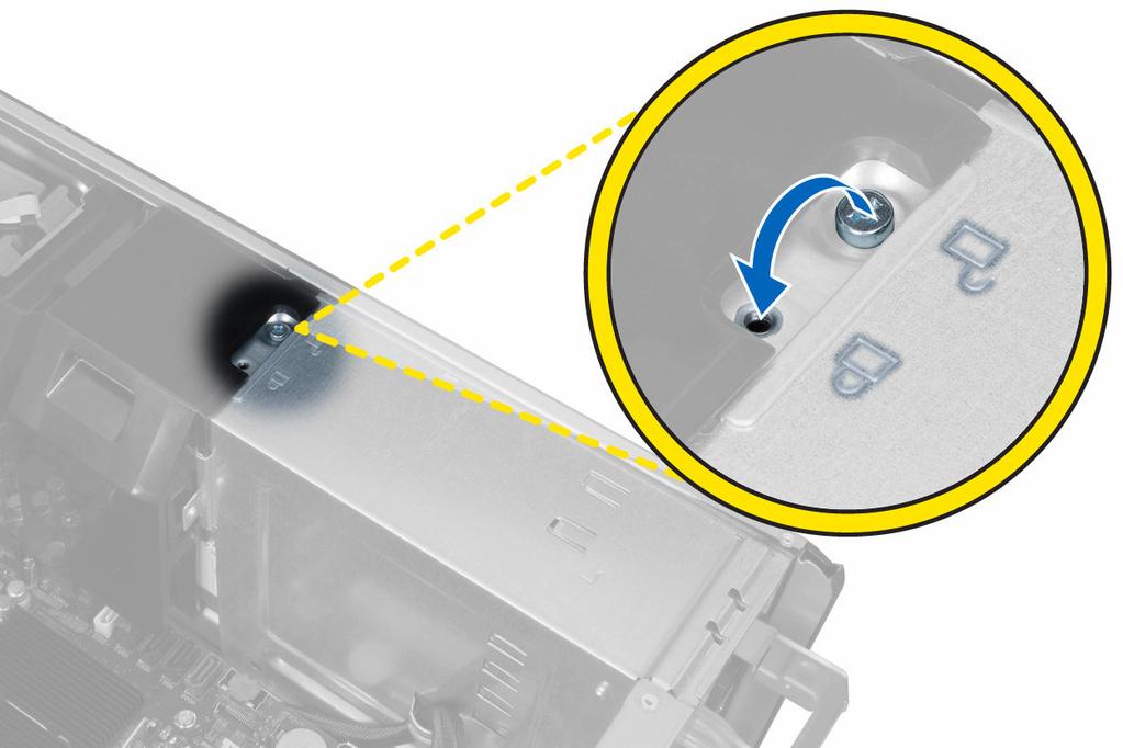
37 Additional Information 3 This section provides information for the additional features that are part of your computer. Memory Module Guidelines To ensure optimal performance of your computer, observe the following general guidelines when configuring your system memory: Memory modules of different sizes can be mixed (for example, 2 GB and 4 GB), but all populated channels must have identical configurations. Memory modules must be installed beginning with the first socket. NOTE: The memory sockets in your computer may be labelled differently depending on the hardware configuration. For example, A1, A2 or 1,2,3. If the quad-rank memory modules are mixed with single or dual-rank modules, the quad-rank modules must be installed in the sockets with the white release levers. If memory modules with different speeds are installed, they operate at the speed of the slowest installed memory module(s). Power Supply Unit (PSU) Lock The PSU lock prevents the removal of the PSU from the chassis. NOTE: To lock or unlock the PSU, always ensure that the cover of the chassis is removed. For information on removing the cover, see Removing the cover. To secure the PSU, remove the screw from the unlock screw location and tighten the screw to the lock location. Similarly, to unlock the PSU, remove the screw from the lock screw location and tighten the screw to the unlock screw location. 37
38 38
39 System Setup 4 System Setup enables you to manage your computer hardware and specify BIOS level options. From the System Setup, you can: Change the NVRAM settings after you add or remove hardware View the system hardware configuration Enable or disable integrated devices Set performance and power management thresholds Manage your computer security Boot Sequence Boot Sequence allows you to bypass the System Setup defined boot device order and boot directly to a specific device (for example: optical drive or hard drive). During the Power-on Self Test (POST), when the Dell logo appears, you can: Access System Setup by pressing <F2> key Bring up the one-time boot menu by pressing <F12> key The one-time boot menu displays the devices that you can boot from including the diagnostic option. The boot-menu options are: Removable Drive (if available) STXXXX Drive Optical Drive Diagnostics NOTE: XXX denotes the SATA drive number. NOTE: Choosing Diagnostics, will display the epsa diagnostics screen. The boot sequence screen also displays the option to access the System Setup screen. Navigation Keys The following table displays the system setup navigation keys. NOTE: For most of the system setup options, changes that you make are recorded but do not take effect until you restart the system. 39
40 Table 1. Navigation Keys Keys Up arrow Down arrow <Enter> Spacebar <Tab> <Esc> <F1> Navigation Moves to the previous field. Moves to the next field. Allows you to select a value in the selected field (if applicable) or follow the link in the field. Expands or collapses a drop down list, if applicable. Moves to the next focus area. NOTE: For the standard graphics browser only. Moves to the previous page till you view the main screen. Pressing <Esc> in the main screen displays a message that prompts you to save any unsaved changes and restarts the system. Displays the System Setup help file. System Setup Options NOTE: Depending on your computer and its installed devices, the items listed in this section may or may not appear. Table 2. General Option System Board Description This section lists the primary hardware features of your computer. System Information Device Information PCI Information Memory Information Processor Information Date/Time Boot Sequence Allows you to set the date and time. The changes to the system date and time takes effect immediately. Allows you to change the order in which the computer attempts to find an operating system. Diskette Drive Internal HDD USB Storage Device CD/DVD/CD-RW Drive Onboard NIC Boot List Option Allows you to change the boot list option. Legacy 40
41 Option Description UEFI Table 3. System Configuration Option Integrated NIC Description Allows you to configure the integrated network controller. The options are: Disabled Enabled (Default Setting) USB Controller Allows you to control the USB controller. The options are: Enable USB Controller (Default Setting) Disable USB Mass Storage Dev Disable USB Controller Serial Port Identifies and defines the serial port settings. You can set the serial port to: Disabled Auto COM1 (Default Setting) COM2 COM3 COM4 NOTE: The operating system may allocate resources even if the setting is disabled. SATA Operation Allows you to configure the internal SATA hard-drive controller. The options are: Disabled ATA AHCI (Default Setting) NOTE: SATA is configured to support RAID mode. USB Configuration Allows you to define the USB configuration. The options are: Enable Boot Support/Front USB Ports/ Rear USB Ports/USB3 Ports SMART Reporting This field controls if the hard drive errors for the integrated drives are reported during system startup. This technology is part of the SMART (Self Monitoring Analysis and Reporting Technology) specification. 41
42 Option Description Enable SMART Reporting - This option is disabled by default. PCI Bus Configuration Allows you to configure the PCI buses. The options are: 64 PCI Buses (Default Setting) Audio Drives Allows you enable or disable the audio feature. Default Setting: Audio is enabled Allows you to configure the SATA drives on board. The options are: SATA-0 SATA-1 HDD Fans Default Setting: All drives are enabled. Allows you to control the HDD fans. Default Setting: depends on the system configuration Table 4. Performance Option Multi Core Support Description This field specifies whether the processor will have one or all cores enabled. The performance of some applications will improve with the additional cores. This option is enabled by default. Allows you to enable or disable multi-core support for the processor. The options are: All (Default Setting) 1 2 Intel SpeedStep C States Control Intel TurboBoost Non-Uniform Memory Access Hyper-Thread Control Allows you to enable or disable the Intel SpeedStep feature. Default Setting: Enable Intel SpeedStep Allows you to enable or disable the additional processor sleep states. Default Setting: All options are enabled. Allows you to enable or disable the Intel TurboBoost mode of the processor. Default Setting: Enable Intel TurboBoost Default Setting: Enabled Allows you to enable or disable the HyperThreading in the processor. 42
43 Option Cache Prefetch RMT Description Default Setting: Enabled Enable Hardware Prefetch and Adjacent Cache Line Prefetch : Default Setting Default Setting: Enabled Table 5. Virtualization Support Option Virtualization Description This option specifies whether a Virtual Machine Monitor (VMM) can utilize the additional hardware capabilities provided by Intel Virtualization technology. Enable Intel Virtualization Technology - Default Setting. VT for Direct I/O Enables or disables the Virtual Machine Monitor (VMM) from utilizing the additional hardware capabilities provided by Intel Virtualization technology for direct I/O. Enable Intel Virtualization Technology for Direct I/O - Default Setting. Table 6. Security Option Intel TXT (LT-SX) Configuration Admin Password Description This option is disabled by default. Allows you to set, change, or delete the administrator (admin) password. NOTE: You must set the admin password before you set the system password. NOTE: Successful password changes take effect immediately. NOTE: Deleting the admin password automatically deletes the system password. NOTE: Successful password changes take effect immediately. System Password Default Setting: Not set Allows you to set, change or delete the system password. NOTE: Successful password changes take effect immediately. Strong Password Default Setting: Not set Allows you to enforce the option to always set strong passwords. Default Setting: Enable Strong Password is not selected. Password Configuration You can define the length of your password. Min = 4, Max = 32 Password Bypass Allows you to enable or disable the permission to bypass the System and the Internal HDD password, when they are set. The options are: Disabled (Default Setting) Reboot bypass Password Change Allows you to enable the disable permission to the System password when the admin password is set. Default Setting: Allow Non-Admin Password Changes is not selected 43
44 Option TPM Security CPU XD Support Computrace Description Allows you to enable the Trusted Platform Module (TPM) during POST. Default Setting: The option is disabled. Allows you to enable the Execute Disable mode of the processor. Default Setting: Enable CPU XD Support Allows you to activate or disable the optional Computrace software. The options are: Deactivate (Default Setting) Disable Activate NOTE: The Activate and Disable options will permanently activate or disable the feature and no further changes will be allowed. Chassis Intrusion Admin Setup Lockout This option is disabled by default. Allows you to prevent users from entering Setup when an Administrator password is set. Default Setting: Disabled Table 7. Power Management Option AC Recovery Description Specifies how the computer will respond when AC power is applied after a AC power loss. You can set the AC Recovery to: Power Off (Default Setting) Power On Last Power State Auto On Time Allows you to set the time at which the computer must turn on automatically. The options are: Disabled (Default Setting) Every Day Weekdays Deep Sleep Control Allows you to define the controls when Deep Sleep is enabled. Disabled (Default Setting) Enabled in S5 only Enabled in S4 and S5 This option is disabled by default. Fan Control Override Wake on LAN Controls the speed of the system fan. The default setting is set to Auto. This option allows the computer to power up from the off state when triggered by a special LAN signal. Wake-up from the Standby state is unaffected by this setting and must be enabled in the operating system. This feature only works when the computer is connected to AC power supply. Disabled - Does not allow the system to power on by special LAN signals when it receives a wake-up signal from the LAN or wireless LAN. 44
45 Option Description LAN Only - Allows the system to be powered on by special LAN signals. This option is disabled by default. Table 8. Maintenance Option Service Tag Asset Tag SERR Messages Description Displays the service tag of your computer. Allows you to create a system asset tag if an asset tag is not already set. This option is not set by default. Controls the SERR message mechanism. This option is not set by default. Some graphics cards require that the SERR message mechanism be disabled. Table 9. POST Behavior Option Numlock LED Keyboard Errors POST Hotkeys Description Specifies if the NumLock function can be enabled when the system boots. This option is enabled by default. Specifies whether keyboard related errors are reported when it boots. This option is enabled by default. Specifies whether the sign-on screen displays a message, that displays the keystroke sequence required to enter the BIOS Boot Option Menu. Enable F12 Boot Option menu - This option is enabled by default. Table 10. System Logs Option BIOS events Description Displays the system event log and allows you to clear the log. Clear Log Updating the BIOS It is recommended to update your BIOS (system setup), on replacing the system board or if an update is available. For notebooks, ensure that your computer battery is fully charged and connected to a power outlet 1. Restart the computer. 2. Go to support.dell.com/support/downloads. 3. If you have your computer's Service Tag or Express Service Code: NOTE: For desktops, the service tag label is available on the front of your computer. NOTE: For notebooks, the service tag label is available on the bottom of your computer. a. Enter the Service Tag or Express Service Code and click Submit. b. Click Submit and proceed to step If you do not have your computer's service tag or express service code, select one of the following: 45
46 a. Automatically detect my Service Tag for me b. Choose from My Products and Services List c. Choose from a list of all Dell products 5. On the application and drivers screen, under the Operating System drop-down list, select BIOS. 6. Identify the latest BIOS file and click Download File. 7. Select your preferred download method in the Please select your download method below window; click Download Now. The File Download window appears. 8. Click Save to save the file on your computer. 9. Click Run to install the updated BIOS settings on your computer. Follow the instructions on the screen. System and Setup Password You can create a system password and a setup password to secure your computer. Password Type System password Setup password Description Password that you must enter to log on to your system. Password that you must enter to access and make changes to the BIOS settings of your computer. CAUTION: The password features provide a basic level of security for the data on your computer. CAUTION: Anyone can access the data stored on your computer if is not locked and left unattended. NOTE: Your computer is shipped with the system and setup password feature disabled. Assigning a System Password and Setup Password You can assign a new System Password and/or Setup Password or change an existing System Password and/or Setup Password only when Password Status is Unlocked. If the Password Status is Locked, you cannot change the System Password. NOTE: If the password jumper is disabled, the existing System Password and Setup Password is deleted and you need not provide the system password to log on to the computer. To enter a system setup, press <F2> immediately after a power-on or reboot. 1. In the System BIOS or System Setup screen, select System Security and press <Enter>. The System Security screen appears. 2. In the System Security screen, verify that Password Status is Unlocked. 3. Select System Password, enter your system password, and press <Enter> or <Tab>. Use the following guidelines to assign the system password: A password can have up to 32 characters. The password can contain the numbers 0 through 9. Only lower case letters are valid, upper case letters are not allowed. Only the following special characters are allowed: space, ( ), (+), (,), (-), (.), (/), (;), ([), (\), (]), (`). 46
47 Re-enter the system password when prompted. 4. Type the system password that you entered earlier and click OK. 5. Select Setup Password, type your system password and press <Enter> or <Tab>. A message prompts you to re-type the setup password. 6. Type the setup password that you entered earlier and click OK. 7. Press <Esc> and a message prompts you to save the changes. 8. Press <Y> to save the changes. The computer reboots. Deleting or Changing an Existing System and/or Setup Password Ensure that the Password Status is Unlocked (in the System Setup) before attempting to delete or change the existing System and/or Setup password. You cannot delete or change an existing System or Setup password, if the Password Status is Locked. To enter the System Setup, press <F2> immediately after a power-on or reboot. 1. In the System BIOS or System Setup screen, select System Security and press <Enter>. The System Security screen is displayed. 2. In the System Security screen, verify that Password Status is Unlocked. 3. Select System Password, alter or delete the existing system password and press <Enter> or <Tab>. 4. Select Setup Password, alter or delete the existing setup password and press <Enter> or <Tab>. NOTE: If you change the System and/or Setup password, re-enter the new password when promoted. If you delete the System and/or Setup password, confirm the deletion when promoted. 5. Press <Esc> and a message prompts you to save the changes. 6. Press <Y> to save the changes and exit from the System Setup. The computer reboots. Disabling a System Password The system's software security features include a system password and a setup password. The password jumper disables any password(s) currently in use. There are 2 pins for the PSWD jumper. NOTE: The password jumper is disabled by default. 1. Follow the procedures in Before Working Inside Your Computer. 2. Remove the cover. 3. Identify the PSWD jumper on the system board. For identifying the PSWD jumper on the system board, see the System Board Components. 4. Remove the PSWD jumper from the system board. 5. Install the cover. NOTE: The existing passwords are not disabled (erased) until the computer boots without the jumper. NOTE: If you assign a new system and/or setup password with the PSWD jumper installed, the system disables the new password(s) the next time it boots. 6. Connect the computer to the electrical outlet and power-on the computer. 7. Power-off the computer and disconnect the power cable from the electrical outlet. 47
48 8. Remove the cover. 9. Replace the jumper on the pins. 10. Install the cover. 11. Follow the procedures in After Working Inside Your Computer. 12. Power-on the computer. 13. Go to the system setup, and assign a new system or setup password. 48
49 Diagnostics 5 If you experience a problem with your computer, run the epsa diagnostics before contacting Dell for technical assistance. The purpose of running diagnostics is to test your computer's hardware without requiring additional equipment or risking data loss. If you are unable to fix the problem yourself, service and support personnel can use the diagnostics results to help you solve the problem. Enhanced Pre-Boot System Assessment (epsa) Diagnostics The epsa diagnostics (also known as system diagnostics) performs a complete check of your hardware. The epsa is embedded with the BIOS and is launched by the BIOS internally. The embedded system diagnostics provides a set of options for particular devices or device groups allowing you to: Run tests automatically or in an interactive mode Repeat tests Display or save test results Run thorough tests to introduce additional test options to provide extra information about the failed device(s) View status messages that inform you if tests are completed successfully View error messages that inform you of problems encountered during testing CAUTION: Use the system diagnostics to test only your computer. Using this program with other computers may cause invalid results or error messages. NOTE: Some tests for specific devices require user interaction. Always ensure that you are present at the computer terminal when the diagnostic tests are performed. 1. Power-on the computer. 2. As the computer boots, press the <F12> key as the Dell logo appears. 3. On the boot menu screen, select the Diagnostics option. The Enhanced Pre-boot System Assessment window is displayed, listing all devices detected in the computer. The diagnostics starts running the tests on all the detected devices. 4. If you wish to run a diagnostic test on a specific device, press <Esc> and click Yes to stop the diagnostic test. 5. Select the device from the left pane and click Run Tests. 6. If there are any issues, error codes are displayed. Note the error code and contact Dell. 49
50 Troubleshooting Your Computer 6 You can troubleshoot your computer using indicators like Diagnostic Lights, Beep Codes, and Error Messages during the operation of the computer. Diagnostic LEDs NOTE: The diagnostic LEDs only serve as an indicator of the progress through the Power-On Self Test (POST) process. These LEDs do not indicate the problem that caused the POST routine to stop. The diagnostic LEDs are located on the front of the chassis next to the power button. These diagnostic LEDs are only active and visible during the POST process. Once the operating system starts to load, they turn off and are no longer visible. Each LED has two possible states of OFF or ON. The most significant bit is labeled with the number 1, and the other three are labeled 2, 3, and 4, as you go down or across the LED stack. The normal operating condition after POST is for all four LEDs to be ON and then turn off as the BIOS hands control over to the operating system. NOTE: The diagnostic lights will blink when the power button is amber or off, and will not blink when it is white. Table 11. POST Diagnostic LED Patterns Diagnostic LEDs The computer is either turned off or is not receiving power The computer is booted and operating normally. PCI device configuration activity is in progress or PCI device failure was detected. A possible processor failure has occurred. Memory modules are detected, but a memory power failure has occurred. If the computer is turned off, connect the AC power-supply and power-on the computer. Remove all peripheral cards from the PCI and PCI-E slots and reboot the computer. If the computer boots, add the peripheral cards back one by one until you find the bad one. Re-seat the processor. If two or more memory modules are installed, remove the modules, then reinstall one module and restart the computer. If the computer starts normally, continue to install additional memory modules (one at a time) until you have identified a faulty module or reinstalled all modules without error. If only one memory 50
51 module is installed, try moving it to a different DIMM connector and re-start the computer. If available, install verified working memory of the same type into your computer. A possible graphics card failure has occurred. A possible hard drive failure has occurred. A possible USB failure has occurred No memory modules are detected. Power connector not installed properly. Ensure that the display/monitor is plugged into a discrete graphic card. Re-seat any installed graphics cards. If available, install a working graphics card into your computer. Re-seat all power and data cables. Reinstall all USB devices and check all cable connections. If two or more memory modules are installed, remove the modules, then reinstall one module and restart the computer. If the computer starts normally, continue to install additional memory modules (one at a time) until you have identified a faulty module or reinstalled all modules without error. If available, install working memory of the same type into your computer. Re-seat the 2x2 power connector from the power supply unit. Memory modules are detected, but a memory configuration or compatibility error has occurred. A possible system board resource and/or hardware failure has occurred. Ensure that no special requirements for memory module/ connector placement exist. Ensure that the memory you are using is supported by your computer. Clear CMOS (Re-seat the coin-cell battery. See Removing and Installing Coin-cell Battery). Disconnect all internal and external peripherals, and restart the computer. If the computer boots, add the peripheral cards back one by one until you find the bad one. 51
52 If the problem persists, the system board / system board component is faulty. A possible system board failure has occurred. Some other failure has occurred. System is in Recovery Mode Boot hand off Disconnect all internal and external peripherals, and re-start the computer. If the computer boots, add the peripheral cards back one by one until you find the bad one. If the problem persists, the system board is faulty. Ensure that the display/monitor is plugged into a discrete graphic card. Ensure that all hard drives and optical-drive cables are properly connected to the system board. If there is an error message on the screen identifying a problem with a device (such as the floppy drive or hard drive), check the device to make sure it is functioning properly. If the operating system is attempting to boot from a device (such as the floppy drive or optical drive), check system setup to ensure the boot sequence is correct for the devices installed on your computer. BIOS checksum failure was detected and the system is now in recovery mode. Indicates end of POST process. LEDs are normally in this state briefly as POST completes. Once the hand-off to the operating system is done, the LEDs turn off. Error Messages There are three types of BIOS error messages that are displayed depending on the severity of the issue. They are: Errors That Halt Your Computer Completely These error messages will halt the computer requiring you to cycle the system's power. The following table lists the error messages. 52
53 Table 12. Errors that halt your computer completely Error Message Error! Non-ECC DIMMs are not supported on this system. Alert! Processor cache size is mismatched. Install like processor or one processor. Alert! Processor type mismatch. Install like processor or one processor. Alert! Processor speed mismatch Install like processor or one processor. Alert! Incompatible Processor detected. Install like processor or one processor. Errors That Do Not Halt Your Computer These error messages will not halt your computer, but will display a warning message, pause for a few seconds, and then continue to boot. The following table lists the error messages. Table 13. Errors that do not halt your computer Error Message Alert! Cover was previously removed. Errors That Soft Halt Your Computer These error messages will cause a soft halt of your computer and you will be prompted to press <F1> to continue or <F2 > to enter the system setup. The following table lists the error messages. Table 14. Errors that soft halt your computer Error Message Alert! Front I/O Cable failure. Alert! Left Memory fan failure. Alert! Right Memory fan failure. Alert! PCI fan failure. Alert! Chipset heat sink not detected. Alert! Hard Drive fan1 failure. Alert! Hard Drive fan2 failure. Alert! Hard Drive fan3 failure. Alert! CPU 0 fan failure. Alert! CPU 1 fan failure. Alert! Memory related failure detected. Alert! Correctable memory error has been detected in memory slot DIMMx. 53
54 Error Message Warning: Non-optimal memory population detected. For increased memory bandwidth populate DIMM connectors with white latches before those with black latches. Your current power supply does not support the recent configuration changes made to your system. Please contact Dell Technical support team to learn about upgrading to a higher wattage power supply. Dell Reliable Memory Technology (RMT) has discovered and isolated errors in system memory. You may continue to work. Memory module replacement is recommended. Please refer to the RMT Event log screen in BIOS setup for specific DIMM information. Dell Reliable Memory Technology (RMT) has discovered and isolated errors in system memory. You may continue to work. Additional errors will not be isolated. Memory module replacement is recommended. Please refer to the RMT Event log screen in BIOS setup for specific DIMM information. 54
55 Technical Specifications 7 NOTE: Offerings may vary by region. The following specifications are only those required by law to ship with your computer. For more information regarding the configuration of your computer, click Start Help and Support and select the option to view information about your computer. Table 15. Processor Feature Type Cache Instruction Cache Data Cache Specification 4, 6, and 8 core Intel Xeon Processor 32 KB 32 KB 256 KB Mid-Level Cache per core up to 20 MB (4C: 10 MB, 6C: 15 MB/12 MB, 8C: 20 MB) Last-Level Cache shared among all cores Table 16. System Information Feature Chipset BIOS chip (NVRAM) Specification Intel C600 chipset 8 MB + 4 MB serial flash EEPROM Table 17. Memory Feature Memory module connector T3600 T5600 T7600 Memory module capacity T3600 / T5600 T7600 Type T3600 T5600 T7600 Minimum memory Specification 4 DIMM slots 8 DIMM slots 16 DIMM slots 1 GB, 2 GB, 4 GB, 8 GB, and 16 GB 1 GB, 2 GB, 4 GB, 8 GB, 16 GB, and 32 GB 1333 and 1600 DDR3 RDIMM ECC/Non-ECC 1333 and 1600 DDR3 RDIMM ECC 1333 and 1600 DDR3 RDIMM and 32 GB LRDIMM ECC 55
Dell Precision Workstation T7610 Owner's Manual
 Dell Precision Workstation T7610 Owner's Manual Regulatory Model: D02X Regulatory Type: D02X002 Notes, Cautions, and Warnings NOTE: A NOTE indicates important information that helps you make better use
Dell Precision Tower 7810 Owner's Manual
 Dell Precision Tower 7810 Owner's Manual Regulatory Model: D01T Regulatory Type: D01T005 Notes, cautions, and warnings NOTE: A NOTE indicates important information that helps you make better use of your
Dell Precision Tower 7910 Owner's Manual
 Dell Precision Tower 7910 Owner's Manual Regulatory Model: D02X Regulatory Type: D02X003 Notes, cautions, and warnings NOTE: A NOTE indicates important information that helps you make better use of your
Dell Precision Tower 5810 Owner's Manual
 Dell Precision Tower 5810 Owner's Manual Regulatory Model: D01T Regulatory Type: D01T006 Notes, cautions, and warnings NOTE: A NOTE indicates important information that helps you make better use of your
Dell Precision Tower 5810 Owner's Manual
 Dell Precision Tower 5810 Owner's Manual Regulatory Model: D01T Regulatory Type: D01T006 Notes, cautions, and warnings NOTE: A NOTE indicates important information that helps you make better use of your
Dell OptiPlex 9010/7010 Mini-Tower Owner's Manual
 Dell OptiPlex 9010/7010 Mini-Tower Owner's Manual Regulatory Model: D09M Regulatory Type: D09M003 Notes, Cautions, and Warnings NOTE: A NOTE indicates important information that helps you make better use
Dell Precision M2800 Owner's Manual
 Dell Precision M2800 Owner's Manual Regulatory Model: P29F Regulatory Type: P29F001 Notes, Cautions, and Warnings NOTE: A NOTE indicates important information that helps you make better use of your computer.
Dell OptiPlex 9020 AIO Owner's Manual
 Dell OptiPlex 9020 AIO Owner's Manual Regulatory Model: W04C Regulatory Type: W04C002 Notes, Cautions, and Warnings NOTE: A NOTE indicates important information that helps you make better use of your computer.
Dell OptiPlex 9020 Small Form Factor Owner's Manual
 Dell OptiPlex 9020 Small Form Factor Owner's Manual Regulatory Model: D07S Regulatory Type: D07S001 Notes, cautions, and warnings NOTE: A NOTE indicates important information that helps you make better
Dell OptiPlex 9010/7010 Small Form Factor Owner's Manual
 Dell OptiPlex 9010/7010 Small Form Factor Owner's Manual Regulatory Model: D03S Regulatory Type: D03S002 Notes, Cautions, and Warnings NOTE: A NOTE indicates important information that helps you make better
Inspiron 22. Service Manual Series. Regulatory Model: W17B Regulatory Type: W17B001
 Inspiron 22 3000 Series Service Manual Regulatory Model: W17B Regulatory Type: W17B001 Notes, cautions, and warnings NOTE: A NOTE indicates important information that helps you make better use of your
Dell Inspiron N5110 Service Manual
 Dell Inspiron N5110 Service Manual Regulatory model: P17F Regulatory type: P17F001 Notes, Cautions, and Warnings NOTE: A NOTE indicates important information that helps you make better use of your computer.
Dell XPS L702X Service Manual
 Dell XPS L702X Service Manual Regulatory model: P09E series Regulatory type: P09E002 Notes, Cautions, and Warnings NOTE: A NOTE indicates important information that helps you make better use of your computer.
Alienware Area-51 R5 Service Manual
 Alienware Area-51 R5 Service Manual Computer Model: Alienware Area-51 R5 Regulatory Model: D03X Regulatory Type: D03X002 Notes, cautions, and warnings NOTE: A NOTE indicates important information that
Dell Latitude 3560 Owner's Manual
 Dell Latitude 3560 Owner's Manual Regulatory Model: P50F Regulatory Type: P50F001 Notes, cautions, and warnings NOTE: A NOTE indicates important information that helps you make better use of your computer.
Inspiron Service Manual. 2-in-1. Computer Model: Inspiron Regulatory Model: P69G Regulatory Type: P69G001
 Inspiron 13 5000 2-in-1 Service Manual Computer Model: Inspiron 13-5378 Regulatory Model: P69G Regulatory Type: P69G001 Notes, cautions, and warnings NOTE: A NOTE indicates important information that helps
Dell OptiPlex 9030 All-In-One Owner's Manual
 Dell OptiPlex 9030 All-In-One Owner's Manual Regulatory Model: W09C Regulatory Type: W09C001 Notes, cautions, and warnings NOTE: A NOTE indicates important information that helps you make better use of
Dell PowerEdge T20 Owner's Manual
 Dell PowerEdge T20 Owner's Manual Regulatory Model: D13M Regulatory Type: D13M001 Notes, Cautions, and Warnings NOTE: A NOTE indicates important information that helps you make better use of your computer.
Dell Latitude E6430 / E6430 ATG Owner's Manual
 Dell Latitude E6430 / E6430 ATG Owner's Manual Regulatory Model: P25G Regulatory Type: P25G001, P25G002 Notes, Cautions, and Warnings NOTE: A NOTE indicates important information that helps you make better
Dell Inspiron XPS and Inspiron 9100 Service Manual
 Dell Inspiron XPS and Inspiron 9100 Service Manual Dell Inspiron XPS and Inspiron 9100 Service Manual Before You Begin Memory Module, Mini PCI Card, and Devices System Components Subwoofer Bluetooth Card
Dell XPS 14z Owner s Manual
 Dell XPS 14z Owner s Manual Computer model: L412z Regulatory model: P24G series Regulatory type: P24G001 Notes, Cautions, and Warnings NOTE: A NOTE indicates important information that helps you make better
Dell OptiPlex 3240 All-In-One Owner's Manual
 Dell OptiPlex 3240 All-In-One Owner's Manual Regulatory Model: W14B Regulatory Type: W14B001 Notes, cautions, and warnings NOTE: A NOTE indicates important information that helps you make better use of
XPS 15 2-in-1. Service Manual. Computer Model: XPS Regulatory Model: P73F Regulatory Type: P73F001
 XPS 15 2-in-1 Service Manual Computer Model: XPS 15-9575 Regulatory Model: P73F Regulatory Type: P73F001 Notes, cautions, and warnings NOTE: A NOTE indicates important information that helps you make better
Dell OptiPlex 7440 All-In-One Owner's Manual
 Dell OptiPlex 7440 All-In-One Owner's Manual Regulatory Model: W11C Regulatory Type: W11C001 Notes, cautions, and warnings NOTE: A NOTE indicates important information that helps you make better use of
Dell OptiPlex 9010/7010 Ultra Small Form Factor Owner's Manual
 Dell OptiPlex 9010/7010 Ultra Small Form Factor Owner's Manual Regulatory Model: D01U Regulatory Type: D01U003 Notes, Cautions, and Warnings NOTE: A NOTE indicates important information that helps you
Dell Latitude E5540 Owner's Manual
 Dell Latitude E5540 Owner's Manual Regulatory Model: P44G Regulatory Type: P44G001 Notes, Cautions, and Warnings NOTE: A NOTE indicates important information that helps you make better use of your computer.
Dell Precision Tower 3420
 Dell Precision Tower 3420 Owner's Manual Regulatory Model: D11S Regulatory Type: D11S001 Notes, cautions, and warnings NOTE: A NOTE indicates important information that helps you make better use of your
Dell Latitude 3460 Owner's Manual
 Dell Latitude 3460 Owner's Manual Regulatory Model: P63G Regulatory Type: P63G001 Notes, cautions, and warnings NOTE: A NOTE indicates important information that helps you make better use of your computer.
Dell Precision Tower 3620 Owner's Manual
 Dell Precision Tower 3620 Owner's Manual Regulatory Model: D13M Regulatory Type: D13M002 Notes, cautions, and warnings NOTE: A NOTE indicates important information that helps you make better use of your
Dell OptiPlex 7440 All-In-One Owner's Manual
 Dell OptiPlex 7440 All-In-One Owner's Manual Regulatory Model: W11C Regulatory Type: W11C001 Notes, cautions, and warnings NOTE: A NOTE indicates important information that helps you make better use of
Dell OptiPlex 9020 AIO Owner's Manual
 Dell OptiPlex 9020 AIO Owner's Manual Regulatory Model: W04C Regulatory Type: W04C002 Notes, Cautions, and Warnings NOTE: A NOTE indicates important information that helps you make better use of your computer.
Dell OptiPlex 9020M Owner's Manual
 Dell OptiPlex 9020M Owner's Manual Regulatory Model: D09U Regulatory Type: D09U001 Notes, Cautions, and Warnings NOTE: A NOTE indicates important information that helps you make better use of your computer.
XPS 13 Convertible Service Manual
 XPS 13 Convertible Service Manual Computer Model: XPS 9365 Regulatory Model: P71G Regulatory Type: P71G001 Notes, cautions, and warnings NOTE: A NOTE indicates important information that helps you make
ALIENWARE AURORA SERVICE MANUAL 01/
 ALIENWARE AURORA SERVICE MANUAL 01/ 01 Notes, Cautions, and Warnings NOTE: A NOTE indicates important information that helps you make better use of your computer. CAUTION: A CAUTION indicates either potential
Dell Latitude 3550 Owner's Manual
 Dell Latitude 3550 Owner's Manual Regulatory Model: P38F Regulatory Type: P38F001 Notes, cautions, and warnings NOTE: A NOTE indicates important information that helps you make better use of your computer.
Alienware X51 Service Manual
 Alienware X51 Service Manual Computer Model: Alienware X51 R3 Regulatory Model: D05S Regulatory Type: D05S003 Notes, cautions, and warnings NOTE: A NOTE indicates important information that helps you make
Dell Latitude Owner's Manual. Regulatory Model: P63G Regulatory Type: P63G001
 Dell Latitude 3460 Owner's Manual Regulatory Model: P63G Regulatory Type: P63G001 Notes, cautions, and warnings NOTE: A NOTE indicates important information that helps you make better use of your computer.
Dell Edge Gateway. Service Manual Series
 Dell Edge Gateway 5000 Series Service Manual Computer Model: Dell Edge Gateway 5000/5100 Regulatory Model: N01G/N02G Regulatory Type: N01G001/N02G001 Notes, cautions, and warnings NOTE: A NOTE indicates
Dell Inspiron 660 Owner s Manual
 Dell Inspiron 660 Owner s Manual Computer model: Inspiron 660 Regulatory model: D11M Regulatory type: D11M002 Notes, Cautions, and Warnings NOTE: A NOTE indicates important information that helps you make
Vostro Owner's Manual
 Vostro 14-5459 Owner's Manual Regulatory Model: P68G Regulatory Type: P68G001 Copyright 2015 Dell Inc. All rights reserved. This product is protected by U.S. and international copyright and intellectual
Dell Vostro Owner's Manual
 Dell Vostro 20 3052 Owner's Manual Regulatory Model: W15B Regulatory Type: W15B002 Notes, cautions, and warnings NOTE: A NOTE indicates important information that helps you make better use of your computer.
Dell Latitude E7270 Owner's Manual
 Dell Latitude E7270 Owner's Manual Regulatory Model: P26S Regulatory Type: P26S001 Notes, cautions, and warnings NOTE: A NOTE indicates important information that helps you make better use of your computer.
Dell Latitude Owner's Manual. Regulatory Model: P63G Regulatory Type: P63G001
 Dell Latitude 3470 Owner's Manual Regulatory Model: P63G Regulatory Type: P63G001 Notes, cautions, and warnings NOTE: A NOTE indicates important information that helps you make better use of your computer.
Dell Precision Tower 3620 Owner's Manual
 Dell Precision Tower 3620 Owner's Manual Regulatory Model: D13M Regulatory Type: D13M002 Notes, cautions, and warnings NOTE: A NOTE indicates important information that helps you make better use of your
Dell Precision Tower 3420 Owner's Manual
 Dell Precision Tower 3420 Owner's Manual Regulatory Model: D11S Regulatory Type: D11S001 Notes, cautions, and warnings NOTE: A NOTE indicates important information that helps you make better use of your
Dell Vostro 5480 Owner's Manual
 Dell Vostro 5480 Owner's Manual Regulatory Model: P41G Regulatory Type: P41G002 Notes, Cautions, and Warnings NOTE: A NOTE indicates important information that helps you make better use of your computer.
Service Manual - Memory Upgrade
 Inspiron 14 3000 Series Service Manual - Memory Upgrade Regulatory Model: P53G Regulatory Type: P53G002 Contents Before working inside your computer...3 Before you begin... 3 Safety instructions... 3 Recommended
Dell Latitude E6230 Owner's Manual
 Dell Latitude E6230 Owner's Manual Regulatory Model: P14T Regulatory Type: P14T001 Notes, Cautions, and Warnings NOTE: A NOTE indicates important information that helps you make better use of your computer.
Dell Precision Mobile Workstation M6800 Owner's Manual
 Dell Precision Mobile Workstation M6800 Owner's Manual Regulatory Model: P30F Regulatory Type: P30F001 Copyright 2015 Dell Inc. All rights reserved. This product is protected by U.S. and international
Thank you for purchasing this Factory Service Manual CD/DVD from servicemanuals4u.com.
 Thank you for purchasing this Factory Service Manual CD/DVD from servicemanuals4u.com. Please check out our ebay auctions for more great deals on Factory Service Manuals: servicemanuals4u Dell Inspiron
Dell Vostro 3252 Owner's Manual
 Dell Vostro 3252 Owner's Manual Regulatory Model: D14S Regulatory Type: D14S001 Notes, cautions, and warnings NOTE: A NOTE indicates important information that helps you make better use of your computer.
Dell Vostro 3250 Owner's Manual
 Dell Vostro 3250 Owner's Manual Regulatory Model: D13S Regulatory Type: D13S001 Notes, cautions, and warnings NOTE: A NOTE indicates important information that helps you make better use of your computer.
Dell Vostro Owner's Manual
 Dell Vostro 15 3549 Owner's Manual Regulatory Model: P45F Regulatory Type: P45F001 Notes, Cautions, and Warnings NOTE: A NOTE indicates important information that helps you make better use of your computer.
OptiPlex Mini Tower
 OptiPlex 3046 - Mini Tower Owner's Manual Regulatory Model: D18M Regulatory Type: D18M002 Notes, cautions, and warnings NOTE: A NOTE indicates important information that helps you make better use of your
Dell Vostro 3250 Owner's Manual
 Dell Vostro 3250 Owner's Manual Regulatory Model: D13S Regulatory Type: D13S001 Notes, cautions, and warnings NOTE: A NOTE indicates important information that helps you make better use of your computer.
Dell Precision 3510 Owner's Manual
 Dell Precision 3510 Owner's Manual Regulatory Model: P48F Regulatory Type: P48F001 Notes, cautions, and warnings NOTE: A NOTE indicates important information that helps you make better use of your computer.
Dell OptiPlex All-in-One. Stand Installation Guide
 Dell OptiPlex All-in-One Stand Installation Guide Notes, cautions, and warnings NOTE: A NOTE indicates important information that helps you make better use of your product. CAUTION: A CAUTION indicates
Dell XPS M1730 Service Manual
 Dell XPS M1730 Service Manual Model PP06XA www.dell.com support.dell.com Notes, Notices, and Cautions NOTE: A NOTE indicates important information that helps you make better use of your computer. NOTICE:
OptiPlex Mini Tower Owner's Manual
 OptiPlex 7040 - Mini Tower Owner's Manual Regulatory Model: D18M Regulatory Type: D18M001 Notes, cautions, and warnings NOTE: A NOTE indicates important information that helps you make better use of your
Thank you for purchasing this Factory Service Manual CD/DVD from servicemanuals4u.com.
 Thank you for purchasing this Factory Service Manual CD/DVD from servicemanuals4u.com. Please check out our ebay auctions for more great deals on Factory Service Manuals: servicemanuals4u Dell Latitude
Dell Latitude E6540 Owner's Manual
 Dell Latitude E6540 Owner's Manual Regulatory Model: P29F Regulatory Type: P29F001 Notes, Cautions, and Warnings NOTE: A NOTE indicates important information that helps you make better use of your computer.
Dell Latitude E5470 Owner's Manual
 Dell Latitude E5470 Owner's Manual Regulatory Model: P62G Regulatory Type: P62G001 Notes, cautions, and warnings NOTE: A NOTE indicates important information that helps you make better use of your computer.
Dell XPS M1530 Service Manual
 Dell XPS M1530 Service Manual Model PP28L www.dell.com support.dell.com Notes, Notices, and Cautions NOTE: A NOTE indicates important information that helps you make better use of your computer. NOTICE:
Dell Latitude E7270 Owner's Manual
 Dell Latitude E7270 Owner's Manual Regulatory Model: P26S Regulatory Type: P26S001 Notes, cautions, and warnings NOTE: A NOTE indicates important information that helps you make better use of your computer.
Dell Latitude E5470. Owner's Manual. Regulatory Model: P62G Regulatory Type: P62G001
 Dell Latitude E5470 Owner's Manual Regulatory Model: P62G Regulatory Type: P62G001 Notes, cautions, and warnings NOTE: A NOTE indicates important information that helps you make better use of your product.
Dell Precision M4600 Owner's Manual
 Dell Precision M4600 Owner's Manual Regulatory Model P13F Regulatory Type P13F001 Notes, Cautions, and Warnings NOTE: A NOTE indicates important information that helps you make better use of your computer.
Dell Latitude E7470 Owner's Manual
 Dell Latitude E7470 Owner's Manual Regulatory Model: P61G Regulatory Type: P61G001 Contents 1 Working on your computer... 6 Safety instructions... 6 Before working inside your computer... 6 Turning off
OptiPlex 7050 Small Form Factor
 OptiPlex 7050 Small Form Factor Owner's Manual Regulatory Model: D11S Regulatory Type: D11S002 Notes, cautions, and warnings NOTE: A NOTE indicates important information that helps you make better use
Dell Latitude 14 Rugged Extreme 7404 Owner's Manual
 Dell Latitude 14 Rugged Extreme 7404 Owner's Manual Regulatory Model: P45G Regulatory Type: P45G001 Notes, Cautions, and Warnings NOTE: A NOTE indicates important information that helps you make better
Dell Latitude E7240 Owner's Manual
 Dell Latitude E7240 Owner's Manual Regulatory Model: P22S Regulatory Type: P22S001 Notes, Cautions, and Warnings NOTE: A NOTE indicates important information that helps you make better use of your computer.
OptiPlex 7050 Tower. Owner's Manual. Regulatory Model: D18M Regulatory Type: D18M003
 OptiPlex 7050 Tower Owner's Manual Regulatory Model: D18M Regulatory Type: D18M003 Notes, cautions, and warnings NOTE: A NOTE indicates important information that helps you make better use of your product.
OptiPlex Small Form Factor Owner's Manual
 OptiPlex 7040 - Small Form Factor Owner's Manual Regulatory Model: D11S Regulatory Type: D11S001 Notes, cautions, and warnings NOTE: A NOTE indicates important information that helps you make better use
Dell Precision series (7710) Owner's Manual
 Owner's Manual") Dell Precision 17 7000 series (7710) Owner's Manual Regulatory Model: P29E Regulatory Type: P29E001 2016 Dell Inc. All rights reserved. This product is protected by U.S. and international copyright and
Dell Precision 17 7000 series (7710) Owner's Manual Regulatory Model: P29E Regulatory Type: P29E001 2016 Dell Inc. All rights reserved. This product is protected by U.S. and international copyright and
Dell Latitude Owner's Manual. Regulatory Model: P73G Regulatory Type: P73G001
 Dell Latitude 7480 Owner's Manual Regulatory Model: P73G Regulatory Type: P73G001 Notes, cautions, and warnings NOTE: A NOTE indicates important information that helps you make better use of your product.
Serial ATA Hot Swap Drive Cage Upgrade Kit for: Intel Server Chassis SC5200 Intel Server Chassis SC5250-E
 Serial ATA Hot Swap Drive Cage Upgrade Kit for: Intel Server Chassis SC5200 Intel Server Chassis SC5250-E A Guide for Technically Qualified Assemblers of Intel Identified Subassemblies/Products Order Number:
Dell Precision series (7710)
") Dell Precision 17 7000 series (7710) Owner's Manual Regulatory Model: P29E Regulatory Type: P29E001 2016 Dell Inc. All rights reserved. This product is protected by U.S. and international copyright and
Dell Precision 17 7000 series (7710) Owner's Manual Regulatory Model: P29E Regulatory Type: P29E001 2016 Dell Inc. All rights reserved. This product is protected by U.S. and international copyright and
OptiPlex Small Form Factor Owner's Manual
 OptiPlex 7040 - Small Form Factor Owner's Manual Regulatory Model: D11S Regulatory Type: D11S001 Notes, cautions, and warnings NOTE: A NOTE indicates important information that helps you make better use
Dell Latitude 3450 Owner's Manual
 Dell Latitude 3450 Owner's Manual Regulatory Model: P51G Regulatory Type: P51G001 Notes, Cautions, and Warnings NOTE: A NOTE indicates important information that helps you make better use of your computer.
Dell Latitude V710/V740 Service Manual
 Dell Latitude V710/V740 Service Manual Dell Latitude V710/V740 Service Manual Before You Begin Preparing to Work Inside the Computer Recommended Tools Computer Orientation Screw Identification System Components
Dell Latitude E5570 Owner's Manual
 Dell Latitude E5570 Owner's Manual Regulatory Model: P48F Regulatory Type: P48F001 Notes, cautions, and warnings NOTE: A NOTE indicates important information that helps you make better use of your computer.
Installing the Cisco ADE 2130 and 2140 Series Appliance Hardware Options
 CHAPTER 4 Installing the Cisco ADE 2130 and 2140 Series Appliance Hardware Options This chapter provides instructions for installing, replacing, and removing various hardware options in your Cisco ADE
Thank you for purchasing this Factory Service Manual CD/DVD from servicemanuals4u.com.
 Thank you for purchasing this Factory Service Manual CD/DVD from servicemanuals4u.com. Please check out our ebay auctions for more great deals on Factory Service Manuals: servicemanuals4u Dell Inspiron
Dell Latitude 3450 Owner's Manual
 Dell Latitude 3450 Owner's Manual Regulatory Model: P51G Regulatory Type: P51G001 Notes, cautions, and warnings NOTE: A NOTE indicates important information that helps you make better use of your product.
Dell Vostro Owner's Manual
 Dell Vostro 24 5460 Owner's Manual Regulatory Model: W12C Regulatory Type: W12C007 Notes, cautions, and warnings NOTE: A NOTE indicates important information that helps you make better use of your computer.
HP ProLiant DL165 G7 Server
 HP ProLiant DL165 G7 Server Installation Instructions Part Number 601464-003 Identifying server components Front panel components Figure 1 Front Panel Components / 4 3.5 LFF HDD Item Description 1 Thumbscrews
Removing and Replacing Parts
 Removing and Replacing Parts Preparing to Work Inside the Computer Recommended Tools Screw Identification System Components Hard Drive Fixed Optical Drive Media Bay Devices Memory Modules Mini PCI Card
SATADOM. for Dell PowerEdge R630, R730, and R730xd systems
 SATADOM for Dell PowerEdge R630, R730, and R730xd systems Notes, cautions, and warnings NOTE: A NOTE indicates important information that helps you make better use of your product. CAUTION: A CAUTION indicates
Dell Vostro Owner's Manual
 Dell Vostro 15 3559 Owner's Manual Regulatory Model: P52F Regulatory Type: P52F003 Notes, cautions, and warnings NOTE: A NOTE indicates important information that helps you make better use of your computer.
Dell Latitude 14 Rugged 5414
 Dell Latitude 14 Rugged 5414 Owner's Manual Regulatory Model: P46G Regulatory Type: P46G002 Notes, cautions, and warnings NOTE: A NOTE indicates important information that helps you make better use of
Installing System Board Options
 CHAPTER 8 Installing System Board Options This section describes how to install the following options: Expansion cards Memory modules Microprocessor This section also includes instructions for replacing
Thank you for purchasing this Factory Service Manual CD/DVD from servicemanuals4u.com.
 Thank you for purchasing this Factory Service Manual CD/DVD from servicemanuals4u.com. Please check out our ebay auctions for more great deals on Factory Service Manuals: servicemanuals4u Dell Inspiron
Dell Latitude E5540 Owner's Manual
 Dell Latitude E5540 Owner's Manual Regulatory Model: P44G Regulatory Type: P44G001 Notes, Cautions, and Warnings NOTE: A NOTE indicates important information that helps you make better use of your computer.
Dell Latitude 6430u Owner's Manual
 Dell Latitude 6430u Owner's Manual Regulatory Model: P36G Regulatory Type: P36G001 Notes, Cautions, and Warnings NOTE: A NOTE indicates important information that helps you make better use of your computer.
Dell Precision 5820 Tower
 Dell Precision 5820 Tower Owner's Manual Regulatory Model: D02T Regulatory Type: D02T002 Notes, cautions, and warnings NOTE: A NOTE indicates important information that helps you make better use of your
Dell Latitude Owner's Manual. Regulatory Model: P73G Regulatory Type: P73G001
 Dell Latitude 7480 Owner's Manual Regulatory Model: P73G Regulatory Type: P73G001 Notes, cautions, and warnings NOTE: A NOTE indicates important information that helps you make better use of your product.
Dell Precision series (7510) Owner's Manual
 Owner's Manual") Dell Precision 15 7000 series (7510) Owner's Manual Regulatory Model: P53F Regulatory Type: P53F001 Copyright 20152016 Dell Inc. or its subsidiaries. All rights reserved. This product is protected by U.S.
Dell Precision 15 7000 series (7510) Owner's Manual Regulatory Model: P53F Regulatory Type: P53F001 Copyright 20152016 Dell Inc. or its subsidiaries. All rights reserved. This product is protected by U.S.
Oracle <Insert Picture Here>
 Slide 1 Oracle Slide 2 WZT-6509 version B Sun Fire Nehalem and Westmere Rack-Mount Server Installation and Replacement Welcome to the installation and replacement
Dell PowerEdge FD332. Owner's Manual. Regulatory Model: E02B Regulatory Type: E02B003
 Dell PowerEdge FD332 Owner's Manual Regulatory Model: E02B Regulatory Type: E02B003 Notes, cautions, and warnings NOTE: A NOTE indicates important information that helps you make better use of your computer.
Dell Latitude E5440 Owner's Manual
 Dell Latitude E5440 Owner's Manual Regulatory Model: P44G Regulatory Type: P44G001 Notes, Cautions, and Warnings NOTE: A NOTE indicates important information that helps you make better use of your computer.
Dell Latitude Owner's Manual. Regulatory Model: P73G Regulatory Type: P73G001
 Dell Latitude 7480 Owner's Manual Regulatory Model: P73G Regulatory Type: P73G001 Notes, cautions, and warnings NOTE: A NOTE indicates important information that helps you make better use of your product.