MULTI SISO HORNET. Datasheet EVALUATION KIT (ORG4502-R01-UAR) O r i g i n G P S. c o m
|
|
|
- Everett McKinney
- 5 years ago
- Views:
Transcription


1 MULTI SISO HORNET EVALUATION KIT (ORG4502-R01-UAR) Datasheet O r i g i n G P S. c o m
2 INDEX 1. SCOPE DISCLAIMER SAFETY INFORMATION ESD SENSITIVITY CONTACT INFORMATION RELATED DOCUMENTATION REVISION HISTORY ABOUT HORNET FAMILY ABOUT MULTI HORNET MODULE ABOUT ORIGINGPS DESCRIPTION SCHEMATICS MAIN BOARD SCHEMATICS BILL OF MATERIALS MAIN BOARD BILL OF MATERIALS ASSEMBLY AND LAYOUT MAIN BOARD PCB TTL-232R-3V3 USB-Serial CONVERTER CABLE ORDERING INFORMATION..12 TABLE INDEX TABLE 1 RELATED DOCUMENTATION... 4 TABLE 2 REVISION HISTORY... 5 TABLE 3 MAIN BOARD BILL OF MATERIALS... 8 TABLE 4 USB-SERIAL CONVERTER CABLE HEADER PIN-OUT TABLE 5 USB-SERIAL CONVERTER CABLE OPERATING PARAMETERS TABLE 6 ORDERING INFORMATION Multi SISO HORNET - ORG4502 Evaluation Kit Datasheet Revision 1.2 Page 2 of 12
3 FIGURE INDEX FIGURE 1 MAIN BOARD SCHEMATICS... 7 FIGURE 2 MAIN BOARD COMPONENTS PLACEMENT...9 FIGURE 3 MAIN BOARD SOLDER MASK...9 FIGURE 4 MAIN BOARD TOP LAYER ROUTING FIGURE 5 MAIN BOARD BOTTOM LAYER ROUTING FIGURE 6 PIN HEADER SOCKET BOTTOM VIEW Multi SISO HORNET - ORG4502 Evaluation Kit Datasheet Revision 1.2 Page 3 of 12
4 1. SCOPE This document describes the features and specifications of Multi SISO Hornet ORG4502 evaluation kit. 2. DISCLAIMER All trademarks are properties of their respective owners. Performance characteristics listed in this document do not constitute a warranty or guarantee of product performance. OriginGPS assumes no liability or responsibility for any claims or damages arising out of the use of this document, or from the use of integrated circuits based on this document. OriginGPS assumes no liability or responsibility for unintentional inaccuracies or omissions in this document. OriginGPS reserves the right to make changes in its products, specifications and other information at any time without notice. OriginGPS reserves the right to conduct, from time to time, and at its sole discretion, firmware upgrades. As long as those FW improvements have no material change on end customers, PCN may not be issued. OriginGPS navigation products are not recommended to use in life saving or life sustaining applications. 3. SAFETY INFORMATION Improper handling and use can cause permanent damage to the product. 4. ESD SENSITIVITY This product is ESD sensitive device and must be handled with care. 5. CONTACT INFORMATION Support - support@origingps.com or Online Form Marketing and sales - marketing@origingps.com Web 6. RELATED DOCUMENTATION DOCUMENT NAME 1 Multi SISO Hornet ORG4502 Datasheet 2 Spider and Hornet - NMEA Protocol Reference Manual 3 Spider and Hornet - OSP Reference Manual 4 Spider and Hornet - OSP GNSS Extensions Reference Manual 5 Spider and Hornet - Low Power Modes Application Note 6 Spider and Hornet - Client Generated Extended Ephemeris Application Note 7 Spider and Hornet - Server Generated Extended Ephemeris Application Note 8 Spider and Hornet - Ephemeris Push Application Note TABLE 1 RELATED DOCUMENTATION Multi SISO HORNET - ORG4502 Evaluation Kit Datasheet Revision 1.2 Page 4 of 12
5 7. REVISION HISTORY REVISION DATE CHANGE DESCRIPTION 1.0 February 16, 2016 First release 1.1 May 25, 2016 Addition of ZIF cable type 1.2 July 4, 2016 Pressing On_Off to start the module update TABLE 2 REVISION HISTORY 8. ABOUT HORNET FAMILY OriginGPS GNSS receiver modules have been designed to address markets where size, weight, stand-alone operation, highest level of integration, power consumption and design flexibility - all are very important. OriginGPS Hornet family breaks size barrier, offering the industry s smallest fully-integrated, highly-sensitive GPS and GNSS modules with integrated antennas or on-board RF connectors. Hornet family features OriginGPS' proprietary NFZ technology for high sensitivity and noise immunity even under marginal signal condition, commonly found in urban canyons, under dense foliage or when the receiver s position in space rapidly changes. Hornet family enables the shortest TTM (Time-To-Market) with minimal design risks. Just connect power supply on a single layer PCB. 9. ABOUT MULTI SISO HORNET MODULE Multi SISO (Snap In Snap Out) Hornet is a complete SiP featuring miniature LGA SMT footprint designed to commit unique integration features for high volume cost sensitive applications. Designed to support compact and traditional applications, Multi Micro Hornet ORG4502 module is a miniature multi-channel GPS/ GLONASS with SBAS, QZSS and other regional overlay systems receiver that continuously tracks all satellites in view, providing real-time positioning data in industry s standard NMEA format. Multi Micro Hornet ORG4502 module offers superior sensitivity and outstanding performance, achieving rapid TTFF in less than one second, accuracy of approximately < 1.5m, and tracking sensitivity of -165dBm. Multi SISO Hornet module integrates OriginGPS proprietary on-board GNSS antenna, dual-stage LNA, RF LDO, SAW filter, TCXO, RTC crystal and RF shield with market-leading SiRFstarV GNSS SoC. Multi SISO Hornet ORG4502 module is introducing industry s lowest energy per fix ratio, unparalleled accuracy and extremely fast fixes even under challenging signal conditions, such as in built-up urban areas, dense foliage or even indoor. Integrated GPS SoC incorporating high-performance microprocessor and sophisticated firmware keeps positioning payload off the host, allowing integration in embedded solutions with low computing resources. Innovative architecture can detect changes in context, temperature, and satellite signals to achieve a state of near continuous availability by maintaining and opportunistically updating its internal fine time, frequency, and satellite ephemeris data while consuming mere microwatts of battery power. Multi SISO Hornet - ORG4502 Evaluation Kit Revision1.2 Page 5 of 12
 proprietary technology for faster position fix and navigation stability even")
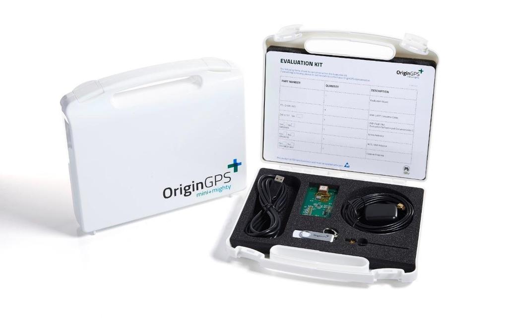
6 10. ABOUT ORIGINGPS OriginGPS is a world leading designer, manufacturer and supplier of miniature positioning modules, antenna modules and antenna solutions. OriginGPS modules introduce unparalleled sensitivity and noise immunity by incorporating Noise Free Zone system (NFZ ) proprietary technology for faster position fix and navigation stability even under challenging satellite signal conditions. Founded in 2006, OriginGPS is specializing in development of unique technologies that miniaturize RF modules, thereby addressing the market need for smaller wireless solutions. 11. DESCRIPTION Evaluation Kit of the ORG4502 GNSS Module comprises the Demo Board, USB to UART Serial Converter Cable, ORG9802 Miniature Passive Antenna Assembly, support Disk-on-key with GPS simulator software for PC and documentation. The Demo Board assembly is built of Main Board, incorporating 1.8V LDO voltage regulator, UART connector, push-button tactile switch for Push-To-Fix interrupt and various test points. The ORG4502 GNSS Module is connected to the Main Board through ZIF connector. Important: When working with ORG4502 EVK, after connecting the FTDI cable you must press the On/Off switch on the EVK board. Only after pressing this switch the module will start working and sending NMEA messages. Multi SISO Hornet - ORG4502 Evaluation Kit Revision1.2 Page 6 of 12 July 4, 2016
7 Main Board
8 13. BILL OF MATERIALS 13.1 MAIN BOARD BILL OF MATERIALS Reference Value Description P/N MFG C1, C2, C4, C9 C10, C11 18pF CAP SMT 18pF ±5% 50V COG GRM1555C1H180JZ01D MURATA C3,C7,C8 4.7µF CAP SMT µF ±10% 6.3V X5R GRM188R60J475KE19D MURATA C5 1µF CAP SMT µF ±10% 10V X5R GRM155R61A105KE15D MURATA D2 LED GREEN LED BLUE SMT mA APT2012SGC KINGBRIGHT J3 ZIF CONN 10pos. 0.5mm pitch FPC ZIF SMT Conn MOLEX Q1 BSS138 N-CH 0.2A 50V SOT23 Power MOSFET BSS138LT1G ON R3, R4, R6 33R RES SMT R ±1% RM04FTN033R TA-I R5 270R RES SMT R ±1% RM04FTN270R TA-I J1 HDR HEADER 6 POS. 0.1 RIGHT ANGLE 2211S-06G-F1 NELTRON U1 LDO 3.3V 200mA LDO W. Discharge Reg. SOT23 ADP160AUJZ-3.3-R7 AD J2 Connector 18 pin connector SW1 SMD TACT SWITCH TJ-532-V-T/R TJ-532 CS SW1 TABLE 3 - MAIN BOARD BILL OF MATERIALS Multi SISO Hornet - ORG4502 Evaluation Kit Revision 1.2 Page 8 of 12

9 14. ASSEMBLY AND LAYOUT 14.1 MAIN BOARD PCB Main Board for the ORG4502 GNSS Module is 2-layer 1.6mm thickness FR4 PCB. FIGURE 2 - MAIN BOARD COMPONENTS PLACEMENT FIGURE 3 - MAIN BOARD SOLDER MASK Multi SISO Hornet - ORG4502 Evaluation Kit Revision 1.2 Page 9 of 12

10 FIGURE 4 MAIN BOARD TOP LAYER ROUTING FIGURE 5 MAIN BOARD BOTTOM LAYER ROUTING Multi SISO Hornet - ORG4502 Evaluation Kit Revision 1.2 Page 10 of 12
 with a 2.54mm ( 0.")
11 15. TTL-232R-3V3 USB-Serial CONVERTER CABLE* The TTL-232R-3V3 is a USB to Serial converter cable that provides a simple way to connect devices with UART interface to PC. The TTL-232R-3V3 uses an FTDI FT232RQ IC which is housed inside the USB Type 'A' connector and is terminated at the end of a 1.8 meter cable (6 ft.) with a 2.54mm ( 0.1) pitch header socket which provides an access to UART standard Transmit Data (TxD) and Receive Data (RxD). These lines are operating at 3.3V LVTTL levels. Also brought out on the header are +5V and GND. FIGURE 6 - PIN HEADER SOCKET BOTTOM VIEW Pin Number Name Type Colour Description 1 GND Power Black Ground supply pin 2 CTS Input Brown Clear To Send input not in use 3 VCC Power Red +5V power source, USB specified 4 TXD Output Orange Asynchronous Data output GPS input 5 RXD Input Yellow Asynchronous Data input GPS output 6 RTS Output Green Request To Send output not in use TABLE 4 - USB-SERIAL CONVERTER CABLE HEADER PIN-OUT Parameter Symbol Test Conditions Min Typ Max Units Power Supply Voltage VCC Defined by USB VB US V Power Supply Current IO ma Output Voltage Low State VOL IOL = 8mA V Output Voltage High State VOH IOH = -3mA V Input Voltage State Switching Threshold VIN Low High V Input Voltage State Switching Hysteresis VHYST High Low mv Operating Temperature TAMB C TABLE 5 - USB-SERIAL CONVERTER CABLE OPERATING PARAMETERS *Note: For more information refer to FTDI Ltd. TTL-232R TTL To USB Serial Converter Range Of Cables Datasheet, Document Reference No.: FT_ Multi SISO Hornet - ORG4502 Evaluation Kit Revision 1.2 Page 11 of 12
12 16. ORDERING INFORMATION O R G R UAR TABLE 7 ORDERING INFORMATION PART NUMBER FW VERSION HW OPTION V CC RANGE PACKAGING SPQ ORG4502-R01-UAR V USB EVALUATION KIT 1 TABLE 6 ORDERABLE DEVICES Recommender ZIF cable: Manufacturer: Molex, P.N For more ZIF cable options: press here Multi SISO Hornet - ORG4502 Evaluation Kit Revision 1.2 Page 12 of 12
MULTI MICRO HORNET EVALUATION KIT ORG1510-MK04-UAR. Datasheet. O r i g i n G P S. c o m
 MULTI MICRO HORNET EVALUATION KIT ORG1510-MK04-UAR Datasheet O r i g i n G P S. c o m Multi Micro Hornet ORG1510MK-04 Evaluation Kit Datasheet Revision 1.0 Page 1 of 15 INDEX 1. SCOPE... 4 2. DISCLAIMER...
MULTI MICRO SPIDER. Datasheet EVALUATION KIT (ORG4033-MK04-UAR) O r i g i n G P S. c o m
 O r i g i n G P S. c o m") MULTI MICRO SPIDER EVALUATION KIT (ORG4033-MK04-UAR) Datasheet O r i g i n G P S. c o m Page 1 of 16 January 18, 2016 INDEX 1. SCOPE... 4 2. DISCLAIMER... 4 3. SAFETY INFORMATION... 4 4. ESD SENSITIVITY...
MULTI MICRO SPIDER EVALUATION KIT (ORG4033-MK04-UAR) Datasheet O r i g i n G P S. c o m Page 1 of 16 January 18, 2016 INDEX 1. SCOPE... 4 2. DISCLAIMER... 4 3. SAFETY INFORMATION... 4 4. ESD SENSITIVITY...
NANO SPIDER (ORG4500) EVALUATION KIT. Datasheet. O r i g i n G P S. c o m. Nano Spider - ORG4400 Evaluation Kit Datasheet Revision 1.
 EVALUATION KIT. Datasheet. O r i g i n G P S. c o m. Nano Spider - ORG4400 Evaluation Kit Datasheet Revision 1.") NANO SPIDER (ORG4500) EVALUATION KIT Datasheet O r i g i n G P S. c o m Nano Spider - ORG4400 Evaluation Kit Datasheet Revision.0 Page of 2 November 23, 204 INDEX. SCOPE...4 2. DISCLAIMER...4 3. SAFETY
NANO SPIDER (ORG4500) EVALUATION KIT Datasheet O r i g i n G P S. c o m Nano Spider - ORG4400 Evaluation Kit Datasheet Revision.0 Page of 2 November 23, 204 INDEX. SCOPE...4 2. DISCLAIMER...4 3. SAFETY
TECHNICAL DESCRIPTION
 Rev 1.1 TECHNICAL DESCRIPTION Fastrax UP501 GPS Receiver This document describes the electrical connectivity and main functionality of the Fastrax UP501 hardware. July 1 st, 2010 Fastrax Ltd. TRADEMARKS
No: SW1.12_4.0.2 V F
 Jupiter-F 2 User s Manual 2010 Navman Wireless OEM. All Rights Reserved. SiRF and SiRF logo are registered trademarks of SiRF Technology, Inc. SiRFstar, SiRFLoc, Push-to-Fix, and Trickle-Power are trademarks
TECHNICAL DESCRIPTION
 REV 0.2 TECHNICAL DESCRIPTION Fastrax Mini Evaluation kit This document describes the electrical connectivity and main functionality of the Mini Evaluation kit hardware. September 10 th, 2007 Fastrax Ltd.
Radiocrafts Embedded Wireless Solutions
 Demonstration Kit User Manual Table of contents TABLE OF CONTENTS... 1 DEMONSTRATION KIT INTRODUCTION... 2 DEMO BOARD INTRODUCTION... 2 BLOCK DIAGRAM... 3 I/O CONNECTION... 4 PROTOTYPING WITH THE RC188XDB...
µ-blox GPS-PS1 GPS Receiver Board based on SiRFstar I/LX TM -Datasheet-
 µ-blox GPS-PS1 GPS Receiver Board based on SiRFstar I/LX TM -Datasheet- June 29, 1999 µ-blox ag Gloriastrasse 35 CH-8092 Zürich Switzerland http://www.u-blox.ch 1 Features ƒ Full Implementation of the
EVALUATION BOARD DATA SHEET EV142
 EV2 Evaluation Board for the AAT272. A Step-Up Current Regulator Introduction The AAT272 EVAL board demonstrates the functionality of the AAT272 and its application as a high current white LED flash driver.
DATASHEET 4D SYSTEMS. uusb-pa5 uusb-pa5-ii. microusb Programming Adaptor TURNING TECHNOLOGY INTO ART. USB to UART Serial Bridge
 DATASHEET TURNING TECHNOLOGY INTO ART microusb Programming Adaptor -II USB to UART Serial Bridge Document Date: 17 th July 2015 Document Revision: 2.0 Uncontrolled Copy when printed or downloaded. Please
SKY : 2.4 GHz Low-Noise Amplifier
 DATA SHEET SKY65405-21: 2.4 GHz Low-Noise Amplifier Applications 802.11b/g/n PC cards, NICs, and USB dongles 802.11b/g/n tablets 802.11b/g/n access points, routers, and gateways 2.4 GHz ISM radios V_ENABLE
GPS Receiver A1035-E
 GPS Receiver A1035-E A Description of Vincotech s GPS Smart Antenna Module A1035-E User s Manual Version 1.3 Hardware Revision 01 Revision History Rev. Date Description 1.0 05-19-08 Initial Draft preliminary
ZLED7002. Toggle (Side-Step) Dual-Channel LED Driver. Datasheet. Features. Brief Description. Benefits. Available Support. Physical Characteristics
 Dual-Channel LED Driver. Datasheet. Features. Brief Description. Benefits. Available Support. Physical Characteristics") Toggle (Side-Step) Dual-Channel LED Driver ZLED7002 Datasheet Brief Description The ZLED7002 toggle (side-step) dual-channel LED driver is one of our ZLED family of LED control ICs. It operates in the
Toggle (Side-Step) Dual-Channel LED Driver ZLED7002 Datasheet Brief Description The ZLED7002 toggle (side-step) dual-channel LED driver is one of our ZLED family of LED control ICs. It operates in the
GPS Module. Ct-G431. Specifications Sheet V0.3
 GPS Module Ct-G431 Specifications Sheet V0.3 Features: SiRF StarIV ultra low power chipset Compact module size for easy integration : 15 x 14 x 2.8 mm UART/ I 2 C pins reserved for customizing special
DATASHEET 4D SYSTEMS TURNING TECHNOLOGY INTO ART. microusb Programming Adaptor. USB to UART Serial Bridge
 TURNING TECHNOLOGY INTO ART DATASHEET microusb Programming Adaptor µusb-pa5 USB to UART Serial Bridge Document Date: 27 th November 2013 Document Revision: 1.1 Uncontrolled Copy when printed or downloaded.
R-78S Evaluation Module. Caution: ESD sensitive. Always follow ESD preventative procedures when handling the product!
 Features Evaluation Module 3.3V from a single AA battery (boost converter or from an external source Efficiency 93%, >80% at 10% load Input range down to 0.65V Input and output current measurement capability
GPS Module. Ct-G431R. Specifications Sheet V0.1
 GPS Module Ct-G431R Specifications Sheet V0.1 Features: SiRF StarIV ultra low power chipset Compact module size for easy integration : 15 x 14 x 2.8 mm UART/ I 2 C pins reserved for customizing special
AN BGA GHz 18 db gain wideband amplifier MMIC. Document information. Keywords. BGA3018, Evaluation board, CATV, Drop amplifier.
 Rev. 2 8 January 2013 Application note Document information Info Keywords Abstract Content BGA3018, Evaluation board, CATV, Drop amplifier This application note describes the schematic and layout requirements
ATtiny817 QTouch Moisture Demo User Guide. Description. Features. AVR 8-bit Microcontrollers USER GUIDE
 AVR 8-bit Microcontrollers ATtiny817 QTouch Moisture Demo User Guide USER GUIDE Description The Atmel ATtiny817 QTouch Moisture Demo Kit demonstrates the high performance capacitive touch support of the
STEVAL-ISA164V1. STNRG388A evaluation board. Description. Features
 STNRG388A evaluation board Data brief Features All STNRG388A pins available on connectors Convenient tool for validating SMED algorithms Graphical interface for SMED configuration On-board components for
Figure 1: Fully Assembled AAT4621EV Evaluation Kit.
 General Description The AAT4621EV evaluation kit is a fully assembled and tested circuit board designed to demonstrate the features of the AAT4621 SmartSwitch supercapacitor charger. The board accepts
Polmaddie6 User Manual. Issue 1.0
 Polmaddie6 User Manual Issue 1.0 2 Foreword PLEASE READ THIS ENTIRE MANUAL BEFORE PLUGGING IN OR POWERING UP YOUR POLMADDIE6 BOARD. PLEASE TAKE SPECIAL NOTE OF THE WARNINGS WITHIN THIS MANUAL. Trademarks
RN-174. WiFly GSX Super Module. Features. Description. Applications. rn-174-ds v1.1 1/24/2011
 www.rovingnetworks.com rn-174-ds v1.1 1/24/2011 WiFly GSX Super Module Features Development board containing the RN-171 module, status LEDs, power regulator Supports chip antenna (-C), PCB Trace antenna
CARDINAL COMPONENTS. Specifications: Min Typ Max Unit
 Re-Configurable 6 Output CMOS TCXO Fixed & Re-Configurable Multi-Frequency Oscillator Intuitive software and I 2 C interface Easily update system Software flexible, quick upgrades and changes Industry-standard
AQ_G24 GSM Terminal Card Motorola Cellular GSM Engine
 AQ_G24 GSM Terminal Card Motorola Cellular GSM Engine Version: 01.01 AQ_G24 Terminal Card_HD_V01.01 17.JUL.2008-1 - Hardware Interface Description 1. Hardware Features of the AQ_G24 Terminal Card Feature
TTL-232R-PCB. TTL to USB Serial Converter PCB. Datasheet
 Future Technology Devices International Ltd TTL-232R-PCB TTL to USB Serial Converter PCB Datasheet Document Reference No.: FT_000065 Version 1.0 Issue Date: 2008-08-28 Future Technology Devices International
Future Technology Devices International Ltd
 Future Technology Devices International Ltd Datasheet Debug Cable for Raspberry Pi Datasheet The cable provides USB to TTL Level UART solutions and 1 Introduction is customised for operation with the Raspberry
RT9055-NGWSC Evaluation Board
 300mA Dual LDO Regulator Purpose The RT9055 is a dual channel, low noise, and low drop Regulator sourcing up to 300mA at each channel. Its input voltage range is from 1.5V to 5.5V and provides an adjustable
Approved by: Date CET Initials Name Justification :20:12 NTJ Niels Thybo Johansen
 Instruction Selection Guideline Document No.: INS10027 Version: 6 Description: This document introduces the ZW0201, and ZW0301 Single Chip based families, and suggests which module to choose for a given
Modtronix Engineering Modular Electronic Solutions SBC28DC. Single board computer for 28 pin DIP PICs
 Modtronix Engineering Modular Electronic Solutions Single board computer for 28 pin DIP PICs Table of Contents 1 Introduction...2 2 Features...4 3 Expansion Connectors...5 3.1 Daughter Board Connectors...5
SE880 RDK User Manual 1VV
 APPLICABILITY TABLE PRODUCT SE880 Reproduction forbidden without written authorization from Telit Communications S.p.A. - All Rights Reserved. Page 2 of 25 SPECIFICATIONS SUBJECT TO CHANGE WITHOUT NOTICE
TTL-232R. TTL to USB Serial Converter Range of Cables. Datasheet
 Future Technology Devices International Ltd TTL-232R TTL to USB Serial Converter Range of Cables Datasheet Document Reference No.: FT_000054 Version 2.03 Issue Date: 2016-05-23 Future Technology Devices
GPS Module. Ct-G430/Ct-G430P. Specifications Sheet V0.2
 GPS Module Ct-G430/Ct-G430P Specifications Sheet V0.2 Features: SiRF StarIV ultra low power chipset Compact module size for easy integration : 24 x 20 x 2.9 mm I 2 C/SPI pins reserved for customizing special
SKY LF: 0.1 to 3.0 GHz GaAs SPDT Switch
 DATA SHEET SKY13323-378LF:.1 to 3. GHz GaAs SPDT Switch Applications WLAN 82.11 b/g networks WLAN repeaters INPUT ISM band radios Low power transmit receive systems OUTPUT1 OUTPUT2 Features Positive voltage
Transcendent Frequency Counter
 Transcendent Frequency Counter with blue 2 x 16 LCD display This manual will guide you how to assemble, test and operate this frequency counter KIT. Features: The transcendent counter has two input channels
MB39C602 LED LIGHTING SYSTEM BULB 9W ZIGBEE CONTROL
 Fujitsu Semiconductor Design (Chengdu) Co. Ltd. User Manual ANA-UM-500001-E-10 MB39C602 LED LIGHTING SYSTEM BULB 9W ZIGBEE CONTROL USER MANUAL Revision History Version Date Updated by Approved by Modifications
TRAKIT-25P. Printings. Version 1.00: 10/03/01 Version 2.00: 01/20/03 Version 2.10: 01/19/04
 TRAKIT-25P Printings Version 1.00: 10/03/01 Version 2.00: 01/20/03 Version 2.10: 01/19/04 TABLE OF CONTENTS SPECIFICATIONS... 1 1.0 GENERAL DESCRIPTION... 2 1.1 Description... 2 1.2 Capabilities and Features...
TTL-232R. TTL to USB Serial Converter Range of Cables. Datasheet
 Future Technology Devices International Ltd TTL-232R TTL to USB Serial Converter Range of Cables Datasheet Document Reference No.: FT_000054 Version 2.01 Issue Date: 2008-08-28 Future Technology Devices
SKY LF: 0.1 to 6.0 GHz GaAs SPDT Switch
 DATA SHEET SKY13446-374LF:.1 to 6. GHz GaAs SPDT Switch Applications Dual-band WLAN systems 82.11 a/b/g/n transmit/receive systems ANT Features Positive low voltage control: and 3. V Low insertion loss:.4
Embedded Navigation Solutions VN 100, VN 200 & VN 300 Development Board User Manual
 Embedded Navigation Solutions VN 100, VN 200 & VN 300 Development Board User Manual VectorNav Technologies Contact Info 10501 Markison Road Phone +1 512 772 3615 Dallas, Texas 75238 Email support@vectornav.com
Propeller Project Board USB (#32810)
") Web Site: www.parallax.com Forums: forums.parallax.com Sales: sales@parallax.com Technical: support@parallax.com Office: (916) 624-8333 Fax: (916) 624-8003 Sales: (888) 512-1024 Tech Support: (888) 997-8267
Web Site: www.parallax.com Forums: forums.parallax.com Sales: sales@parallax.com Technical: support@parallax.com Office: (916) 624-8333 Fax: (916) 624-8003 Sales: (888) 512-1024 Tech Support: (888) 997-8267
xpico 110 Wired Device Server Module Evaluation Kit User Guide
 xpico 110 Wired Device Server Module Evaluation Kit User Guide Part Number 900-788-R Revision A April 2017 Intellectual Property 2017 Lantronix, Inc. All rights reserved. No part of the contents of this
xpico 200 Series Evaluation Kit User Guide
 xpico 200 Series Evaluation Kit User Guide This guide describes how to setup the xpico 200 series evaluation kit and provides the information needed to evaluate the included xpico 240 or xpico 250 embedded
CARDINAL COMPONENTS. FREQUENCY A MHz. Specifications: Min Typ Max Unit
 Re-Configurable 6 Output PECL TCXO Fixed & Re-Configurable Multi-Frequency Oscillator Intuitive software and I 2 C interface Easily update system Industry-standard packaging saves on board space Mult.
SL869-V3 EVK User Guide. 1VV Rev
 SL869-V3 EVK User Guide 1VV0301306 Rev.0 2016-08-19 APPLICABILITY TABLE PRODUCT SL869-V3 Reproduction forbidden without written authorization from Telit Communications S.p.A. - All Rights Reserved. Page
LM48555 Evaluation Board
 LM48555 Evaluation Board Quick Start Guide 1) Apply power supply voltage to positive terminal of JU4, and source ground to the negative terminal. 2) Short the terminals of JU1 to release the device from
Radiocrafts IESM-Series Expansion Cards User Manual
 Radiocrafts IESM-Series Expansion Cards User Manual Table of contents TABLE OF CONTENTS... 1 QUICK START GUIDE... 2 PRODUCT DESCRIPTION... 3 SUPPORTED PROTOCOLS AND NETWORK STANDARDS... 3 APPLICATIONS...
OriginIoT ORG EVK USER GUIDE OriginIoT EVK User Guide Rev O r i g i n G P S. c o m
 OriginIoT ORG2101 - EVK USER GUIDE O r i g i n G P S. c o m - 1 - INDEX 1. SCOPE... 5 2. DISCLAIMER... 5 3. SAFETY INFORMATION... 5 4. ESD SENSITIVITY... 5 5. CONTACT INFORMATION... 5 6. RELATED DOCUMENTATION...
Wireless Smart Charging System for Mobile Devices
 Western Washington University Wireless Smart Charging System for Mobile Devices EE 492 Jacie Unpingco 3-17-2016 TABLE OF CONTENTS 1. Design Change Form...1 2. Schematic Sheets a. MCU, Battery, and LEDs
RN-174. WiSnap M2 Super Module. Features. Description. Applications. ~ page 1 ~ rn-174-ds v1.1 6/1/2011
 WiSnap M2 Super Module Features Development board containing the RN-171 module, status LEDs, power regulator Supports chip antenna (RN-174-C), PCB Trace antenna (RN-174-P), wire antenna (RN- 174-W) and
EVAL6494L. Demonstration board for L6494L gate driver. Description. Features
 Demonstration board for L6494L gate driver Description Data brief Features Driver current capability: 2 A source, 2.5 A sink Integrated bootstrap diode Single input and shutdown pin Adjustable deadtime
GRF2505. Linear PA Driver/Ultra-low Noise Amplifier; GHz. Features. Applications. Preliminary. Product Description. Functional Block Diagram
 Linear PA Driver/Ultra-low Noise Amplifier; 4.0-6.0 GHz Package: 6-Pin DFN Product Description Features Broadband: 4.0 GHz to 6.0 GHz 0.80 db Noise Figure at 5.5 GHz 13.2 db gain, +33 dbm OIP3 and +20.5
C232HD. USB 2.0 Hi-Speed to UART Cable. Datasheet
 Future Technology Devices International Ltd C232HD USB 2.0 Hi-Speed to UART Cable Datasheet Document Reference No.: FT_000430 Issue Date: 2012-03-14 Future Technology Devices International Limited (FTDI)
GPS Module. Ct-G432. Specifications Sheet V0.1
 GPS Module Ct-G432 Specifications Sheet V0.1 Features: SiRF StarIV internal ROM-based ultra low power chipset Compact module size for easy integration : 10.6 x 10 x 2.3 mm Ct-G432 module provide an I 2
Wireless Smart Charging System for Mobile Devices
 Western Washington University Wireless Smart Charging System for Mobile Devices EE 492 Jacie Unpingco 5 June 2016 TABLE OF CONTENTS 1. Design Change Form...1 2. Schematic Sheets a. MCU, Battery, and LEDs
Preliminary. PACKAGE - 28-pin MLP (5mm X 5mm) Example Circuit Diagram CP V. 48MHz Oscillator. USB Function Controller 512B EEPROM
 Example Circuit Diagram CP V. 48MHz Oscillator. USB Function Controller 512B EEPROM") Preliminary Single-Chip USB to UART Bridge SINGLE-CHIP USB to UART DATA TRANSFER - Integrated USB Transceiver; No External Resistors Required - Integrated Clock; No External Crystal Required - Integrated
Preliminary Single-Chip USB to UART Bridge SINGLE-CHIP USB to UART DATA TRANSFER - Integrated USB Transceiver; No External Resistors Required - Integrated Clock; No External Crystal Required - Integrated
Future Technology Devices International Limited
 Future Technology Devices International Limited Datasheet LC234X Development Module 1 Introduction The LC234X module is a low cost USB to serial UART bridge using the FTDI FT234XD. In addition to the 4
Features. Evaluation Module. Evaluation Module R-78S EVM-1
 Features Evaluation Module 3.3V from a single AA battery or from an external source (boost converter) Efficiency 93%, >80% at 0% load Input voltage range down to 0.65V Input and output power measurement
Skywire LTE LE910 Embedded Cellular Modem Verizon Network Datasheet. NimbeLink Corp Updated: September 2014
 Skywire LTE LE910 Embedded Cellular Modem Verizon Network Datasheet NimbeLink Corp Updated: September 2014 PN 30012 rev 4 NimbeLink Corp All Rights Reserved. 1 1. INTRODUCTION... 3 1.1 ORDERABLE PART NUMBERS...
Incremental Encoder Adapter Page 1 of 8. Description. Features. Differential Cable Driver/Receiver:
 Description Page 1 of 8 Differential Cable Driver/Receiver: The EA-D-L-10- is a differential RS-422 cable driver which converts the singleended A/B/I output from USD's single-ended incremental encoders
SKY LF: 20 MHz to 6.0 GHz GaAs SPDT Switch
 DATA SHEET SKY13587-378LF: 2 MHz to 6. GHz GaAs SPDT Switch Applications WLAN 82.11 a/b/g/n networks Low power transmit/receive systems INPUT Industrial IoT Lighting OUTPUT1 OUTPUT2 Smart energy Connected
Skywire Hardware Design Checklist NimbeLink Corp Updated: August 2018
 Skywire Hardware Design Checklist NimbeLink Corp Updated: August 2018 PN 1001787 rev 2 NimbeLink Corp. All Rights Reserved. 1 Table of Contents Table of Contents 2 Introduction 3 Scope 3 Orderable Devices
12-NOV E32 RYN25AI. High performance GPS / Glonass Antenna Module. Datasheet
 12-NOV-2018 56312E32 High performance GPS / Glonass Antenna Module Datasheet PRODUCT DESCRIPTION The REYAX GPS/Glonass receiver module with embedded GPS/Glonass antenna enables high performance navigation
Evaluates: MAX32620, MAX77650, MAX MAX32620FTHR Rapid Development Platform. Benefits and Features. General Description
 General Description The MAX32620FTHR board is a rapid development platform designed to help engineers quickly implement battery-optimized solutions with the MAX32620 Arm Cortex -M4 microcontroller with
Rapid40iXL PIC Prototyping PCB User Manual
 Description This is a PCB designed to facilitate the rapid prototyping of a device based on a 40 pin Microchip PIC microcontroller. To allow users to focus on their application, we take care of key housekeeping
SIM28M/28ML GPS Receiver Modem
 CAMPUS COMPONENT Pvt. Ltd. 1 DISCLAIMER Information furnished is believed to be accurate and reliable at the time of publication. However, Campus Component Pvt. Ltd. assumes no responsibility arising from
Receivers & Tracking products
 9/2010 www.fastraxgps.com Receivers & Tracking products 01 UP5 W! NE 20 IT5! W NE! 30 NEW IT4 Choose from the widest range of GPS receiver solutions in the world! FASTRAX PRODUCT MATRIX Product Description
Datasheet BT85x Series Development Kits
 A BT85x Series Development Kits Applicable to the following Laird part numbers: DVK-BT850-SA DVK-BT850-ST Version 1.0 REVISION HISTORY Version Date Notes Contributor Approver 1.0 12 Jan 2018 Initial Release
GLONASS SHIELD USER MANUAL
 GLONASS SHIELD USER MANUAL 11 MARCH, 2013 THANK YOU FOR BUYING OUR PRODUCT! Congratulations! You have purchased our GLONASS/GPS Shield expansion board used to determine geographical coordinates and time
Product description Rev. 3 11/06/14
 EZ863-2G - GNSS Product description Rev. 3 11/06/14 1 Table of Contents 1. Overview... 4 2. General Description... 4 2.1 Dimensions... 4 2.2 Weight... 4 2.2 Installation... 5 2.3 Casing material... 6 2.4
Note : Power consumption and sample rate will vary according to different firmware versions.
 1.0 Product Page 2 of 6 PenMount 1400A control board is one of the cutting-edge innovations from PenMount. A collectively integrated feature with USB / RS232 interface supporting 11.0 to 15.0 projected
TD12xx/TD15xx EVB. EVB for LGA25 TDnext Modules Rev 1.1 User s Guide. EVALUATION BOARD USER S GUIDE FOR TDnext LGA25 MODULE
 EVALUATION BOARD USER S GUIDE FOR TDnext LGA25 MODULE August 2017 - Rev 1.1 http://rfmodules.td-next.com Page 1 Disclaimer: The information in this document is provided in connection with Telecom Design
MIC826. General Description. Features. Applications. Typical Application
 Voltage Supervisor with Watchdog Timer, Manual Reset, and Dual Outputs In 1.6mm x 1.6mm TDFN General Description The is a low-current, ultra-small, voltage supervisor with manual reset input, watchdog
Datasheet BT860 Development Kit
 A BT860 Development Kit Applicable to the following Laird part numbers: - DVK-BT860-SA Integrated antenna version - DVK-BT860-ST Trace pin for external antenna version Version 1.0 REVISION HISTORY Version
AN BGA301x Wideband Variable Gain Amplifier Application. Document information. Keywords
 Rev. 2 3 February 2014 Application note Document information Info Content Keywords BGA3015, BGA3018, BAP70Q, CATV, Line-up, VGA, Evaluation board Abstract This application note describes the schematic
Product Datasheet: DWM1001-DEV DWM1001 Module Development Board. Key Features and Benefits
 Product Datasheet: DWM1001-DEV DWM1001 Module Development Board Plug-and-Play Development Board for evaluating the performance of the Decawave DWM1001 module Easily assemble a fully wireless RTLS system,
Low-Power-Radio Transceiver IC
 Addressed Mode With Acknowledge Broadcast Mode Automatic Retry Serial Interface Stand Alone Operation Achieves Maximum Range From RF Modules Flow Control Option Two Telemetry I/O Lines (addressed mode
RFSA2023TR7. Voltage Controlled Attenuator. Product Overview. Key Features. Functional Block Diagram Applications. Ordering Information
 Product Overview Qorvo's is a fully monolithic analog voltage control attenuator (VCA) featuring exceptional linearity over 30dB adjustment range with on-chip temperature compensation. incorporates a revolutionary
SKY LF: 0.1 to 3.0 GHz GaAs SPDT Switch
 DATA SHEET SKY13319-374LF:.1 to 3. GHz GaAs SPDT Switch Applications Two-way radios WiMAX WLANs J2 J1 Features Broadband frequency range:.1 to 3. GHz Low insertion loss:.4 @ 1 GHz High isolation: 25 @
DATASHEET. 4.3 Embedded SPI Display. 4DLCD-FT843 Powered by the FTDI FT800 Video Engine. Document Date: 25 th September 2013 Document Revision: 0.
 DATASHEET 4.3 Embedded SPI Display 4DLCD-FT843 Powered by the FTDI FT800 Video Engine Document Date: 25 th September 2013 Document Revision: 0.4 Uncontrolled Copy when printed or downloaded. Please refer
TMR1202. General Description. TMR Bipolar Switch. Features and Benefits. Applications
 General Description TMR1202 TMR Bipolar Switch The TMR1202 is a digital bipolar magnetic switch that integrates TMR and CMOS technology in order to provide a magnetically triggered digital switch with
HZX N03 Bluetooth 4.0 Low Energy Module Datasheet
 HZX-51822-16N03 Bluetooth 4.0 Low Energy Module Datasheet SHEN ZHEN HUAZHIXIN TECHNOLOGY LTD 2017.7 NAME : Bluetooth 4.0 Low Energy Module MODEL NO. : HZX-51822-16N03 VERSION : V1.0 1.Revision History
ACT8945AEV. ACT8945A Evaluation Kit FEATURES GENERAL DESCRIPTION QUICK START GUIDE. Rev 0, 08-Aug-13
 FEATURES Fully Assembled and Tested PCB Allows Simple Evaluation of the ACT8945A Probe Points for Easy Measurement QUICK START GUIDE 1) Variable Power Supply 2) DMM Recommended Equipment 3) Load Resistors
Skywire GPRS Embedded Cellular Modem Datasheet
 Skywire GPRS Embedded Cellular Modem Datasheet NimbeLink Corp Updated: October 2017 PN 30007 rev 6 NimbeLink Corp. 2017. All rights reserved. 1 Table of Contents Table of Contents 2 Introduction 3 Orderable
TTL-234X. TTL234X Series Range of Cables. Datasheet
 Future Technology Devices International Ltd TTL-234X TTL234X Series Range of Cables Datasheet Document Reference No.: FT_001394 Issue Date: 2017-02-22 Future Technology Devices International Limited (FTDI)
AVR-P20 development board Users Manual
 AVR-P20 development board Users Manual All boards produced by Olimex are ROHS compliant Revision A, October 2005 Copyright(c) 2009, OLIMEX Ltd, All rights reserved Page 1 INTRODUCTION: The AVR Microcontrollers
MSP430AFE253 Development Board (CL-MSPDB-AFE) User Guide
 User Guide") MSP430AFE253 Development Board (CL-MSPDB-AFE) User Guide www.cascologix.com Page 1 Table of Contents 1 Revision History...3 2 Features...3 3 Board Features...4 3.1 Mini USB Connector...4 3.2 External Power
MSP430AFE253 Development Board (CL-MSPDB-AFE) User Guide www.cascologix.com Page 1 Table of Contents 1 Revision History...3 2 Features...3 3 Board Features...4 3.1 Mini USB Connector...4 3.2 External Power
ELAN DIGITAL SYSTEMS LTD.
 ELAN DIGITAL SYSTEMS LTD. LITTLE PARK FARM ROAD, SEGENSWORTH WEST, FAREHAM, HANTS. PO15 5SJ. TEL: (44) (0)1489 579799 FAX: (44) (0)1489 577516 e-mail: support@pccard.co.uk website: http://www.pccard.co.uk
Rapid28iXL PIC Prototyping PCB User Manual
 Description Features This is a PCB designed to facilitate the rapid prototyping of a device based on a 28 pin Microchip PIC microcontroller. To allow users to focus on their application, we take care of
IMPORTANT NOTICE. As a result, the following changes are applicable to the attached document.
 IMPORTANT NOTICE Dear customer, As from August 2 nd 2008, the wireless operations of NXP have moved to a new company, ST-NXP Wireless. As a result, the following changes are applicable to the attached
October 2002 PMP Portable Power SLVU074
 User s Guide October 2002 PMP Portable Power SLVU074 IMPORTANT NOTICE Texas Instruments Incorporated and its subsidiaries (TI) reserve the right to make corrections, modifications, enhancements, improvements,
Serial Port Plug - F2M01SXA Brief Datasheet. Features. Applications. General Description. Provides transparent RS-232 serial cable replacement.
 Serial Port Plug - F2M01SXA Features Provides transparent RS-232 serial cable replacement. No need for external drivers. Power is supplied via the D-SUB or mini-usb connector. Supports the Bluetooth Serial
USB MOD1 - USB Plug and Play Serial Development Module
 USB MOD - USB Plug and Play Serial Development Module The USB MOD shown in diagram, is a low-cost integrated module for transferring serial data over USB. Based on the FTDI FTUAM USB UART IC, the USB MOD
SKYA21001: 20 MHz to 3.0 GHz SPDT Switch
 DATA SHEET SKYA21001: 20 MHz to 3.0 GHz SPDT Switch Automotive Applications Infotainment Automated toll systems Garage door opener 802.11 b/g/n WLAN, Bluetooth systems Wireless control systems Outdoor
Future Technology Devices International Ltd. USB to RS422 Serial Converter Cable. Datasheet
 Future Technology Devices International Ltd USB to RS422 Serial Converter Cable Datasheet Document Reference No.: FT_000116 Issue Date: 18-01-2010 Neither the whole nor any part of the information contained
ADP1047/8DC1-EVALZ. The daughter card can be connected to any existing ADP1047/ADP1048 evaluation board or reference design.
 ADP1047/ADP1048 Daughter Card Evaluation Board FEATURES ADP1047/ADP1048 Daughter Card with I2C interface Retrofit controller to any topology or existing design Software GUI Low component count ADP1047/ADP1048
SBC65EC. Ethernet enabled Single Board Computer
 Ethernet enabled Single Board Computer Table of Contents 1 Introduction...2 2 Features...3 3 Daughter Board Connectors...4 3.1 As a Daughter Board...5 3.2 Expansion boards...5 4 Interfaces...5 4.1 Ethernet...5
Radiocrafts IESM-Series Expansion Cards User Manual
 Radiocrafts IESM-Series Expansion Cards User Manual Table of contents TABLE OF CONTENTS... 1 QUICK START GUIDE... 2 PRODUCT DESCRIPTION... 3 SUPPORTED PROTOCOLS AND NETWORK STANDARDS... 3 APPLICATIONS...
AirPrime XM0110 GPS Module. Technical Brief. WM_DEV_XM0110_PTS_ February 28, 2011
 WWW.INFOPULSAS.LT info@infopulsas.lt AirPrime XM0110 GPS Module Technical Brief WM_DEV_XM0110_PTS_001 004 February 28, 2011 Important Notice Due to the nature of wireless communications, transmission and
Features. LOAD SWITCH or PMIC. LOAD SWITCH or PMIC /RESET
 Dual-Input Push Button Reset IC with Immediate and Delayed Outputs General Description The is a two input, two output push-button reset IC. It will generate a reset pulse for a factory-programmed reset