Setup and Users Manual
|
|
|
- John Abner Robbins
- 5 years ago
- Views:
Transcription


1 Setup and Users Manual TSHARC 12v Touch Screen Controller Board Supports 4-, 5- & 8-Wire Analog Resistive Touch Screens Supports RS-232 and PS/2 Version 1.1R Document Revision and Copyright Document Name: 06B_TSHARC_V_1.1_Users Document Date: August 27, 2009 Copyright Microchip Technology Inc All rights reserved Microchip TSHARC and UniWinDriver are the exclusive trademarks of Microchip Technology Inc. All Rights Reserved. Contact Information Microchip Technology Inc 9055 N. 51st Street Unit H Brown Deer, WI Main Phone: Main Fax:
2 Important Documents and User Information Use this document as a guide only. The information contained in this document is subject to change without notice. This document, and all of its contents, is protected under International and U.S. copyright law. Microchip Technology trademarks, patents and copyrights are the exclusive property of Microchip Technology Inc. and may not be used without the express written consent of Microchip Technology Inc. Due to the vast range of application variables that fall outside of Microchip s expertise and control, Microchip assumes no responsibility for the usability or the suitability of Microchip products in customer application(s). Microchip assumes those responsible for the application and use of Microchip Technology products and documentation have taken all necessary steps to insure that the application of Microchip products meet any and all safety and performance requirements including any laws, regulations, codes and standards associated with the application. In no case does Microchip warrant the usability or suitability of its products in any medical, aviation, military or other life critical applications. User should contact Microchip Technology before integrating any Microchip hardware or software product into these types of applications. All Microchip standard software products, including but not limited to device driver software, are provided as is and may be used exclusively with an authentic Microchip TSHARC touch screen controller. Microchip does not guarantee the usability of any of its software products. Microchip Technology warrants to the original purchaser, or a third party who is listed on the Microchip Multi Party Authorization Agreement, that for the warranty period identified by Microchip warranty for the specific product that you have purchased, that the goods will be in conformance with Microchip specifications. In addition to Microchip specifications, the warrantee includes Non-Microchip specifications agreed-to, in writing, by Microchip in advance for the limited purpose between the customer and Microchip Technology Inc. The warrantee also insures that the goods will be free from defects in design and material for the warrantee period. Microchip Technology, at its option, will repair or replace the nonconforming or defective goods, issue a credit memorandum, or refund the purchase price, as its sole obligation: provided that the nonconforming or defective goods are rejected in writing (including a reasonable failure analysis statement) to Microchip Technology and returned to Microchip Technology within the relevant warranty period and provided that the nonconformance or defect was not caused by misuse, alteration, accident, or abnormal conditions of storage, operation or handling, as determined by Microchip Technology. THIS WARRANTY IS YOUR SOLE AND EXCLUSIVE REMEDY AND IS IN LIEU OF ALL OTHER WARRANTIES, EXPRESS OR IMPLIED, INCLUDING ANY IMPLIED WARRANTY OF MERCHANTABILITY OR FITNESS FOR A PARTICULAR PURPOSE, FURTHER, MICROCHIP TECHNOLOGY INC SHALL NOT BE LIABLE FOR ANY DIRECT, INDIRECT, SPECIAL, INCIDENTAL OR CONSEQUENTIAL DAMAGE OR LOSSES, INCLUDING LOSS OF PROFITS, BUSINESS INTERRUPTION, OR OTHER PECUNIARY LOSS, WHETHER ARISING FROM BREACH OF WARRANTY OR BASED ON CONTRACT, FUNDAMENTAL BREACH OR ANY OTHER THEORY. SINCE SOME JURISDICTIONS DO NOT ALLOW LIMITATIONS OF THE TERMS OF ANY IMPLIED WARRANTY, OR EXCLUSION OR LIMITATION OF INCIDENTAL OF CONSEQUENTIAL DAMAGES, THE LIMITATIONS AND EXCLUSIONS OF THIS WARRANTY MAY NOT APPLY TO YOU. General Information Mailing address World Wide Web Support Microchip Technology Inc North 51 st Street, Suite H Brown Deer, WI Phone: Fax: Copyright Information This manual is Microchip Technology Inc. Reproduction of the contents of this copyrighted material in whole or in part, by any means, mechanically or electronic, for any purpose, without the written permission of Microchip Technology Inc is prohibited. Microchip Technology Inc., Microchip TSHARC, the TSHARC logo, and UniWinDriver are Trademarks of Microchip Technology Inc. All Rights Reserved. Edition Information Printed on: August 27, 2009 Document Part number: 06B_TSHARC_V_1.1_Users
3 Table of Contents IMPORTANT DOCUMENTS AND USER INFORMATION... 2 GENERAL INFORMATION... 2 MAILING ADDRESS... 2 WORLD WIDE WEB... 2 SUPPORT ADDRESS... 2 TABLE OF CONTENTS... 3 INTRODUCTION... 4 PRODUCT DESCRIPTION... 4 PART NUMBER... 4 TSHARC 12V CORE FEATURES... 4 TOUCH SCREEN OVERVIEW... 5 SOFTWARE DEVICE DRIVERS... 5 TSHARC-12 V MECHANICAL DIAGRAM... 6 INTEGRATING THE TSHARC 12V CONTROLLER... 7 JUMPER CONFIGURATIONS... 7 POWER JUMPER SETTINGS... 7 COMMUNICATION CONNECTION DIAGRAMS... 7 RS-232 COMMUNICATION... 7 PS/2 COMMUNICATION... 8 COMMUNICATION FORMAT... 8 TOUCH SCREEN CONNECTION DIAGRAMS... 9 DEVELOPED AND SUPPORTED IN-HOUSE PRIVATE LABELED DRIVERS TSHARC CONTROLLER CHIP SOLUTIONS SUPPORT SERVICES NOTES
4 Introduction This manual has been written for users of the Microchip TSHARC 12V touch screen micro-controller board. The TSHARC touch screen controller boards and software described within this document are assumed to be used with four, five or eight wire analog resistive touch screen products manufactured by a variety of touch screen manufacturers. Touch screens between manufacturers vary with regards to light transmission, sensitivity, contact resistance, capacitance and other electrical characteristics. Because touch screen quality and electrical characteristics may vary between touch screen technologies and manufacturers the actual, overall performance may vary between touch screen overlay manufacturers products. A great deal of attention has been paid to eliminate potential problems with various touch screen manufacturers. We have identified substantial specification variance within each manufacturer and between manufacturers touch screens. While most of the manufactures we tested did fall within a functional specification, it is important to request electrical and mechanical specifications from your touch screen overlay manufacturer to insure uniform quality and performance. The specification details that should be provided by your touch screen overlay supplier include lead to lead resistance, sheet resistance, and linearity of ITO. Product Description The TSHARC 12v controller board can be configured for RS-232 and PS/2 communications and for any manufacturers 4, 5 or 8 wire analog resistive touch sensors.. Part Number Jumper-Configurable for sensor and communication type HS V-03 TSHARC 12V Core Features RoHS Compliant True 12-bit ratio metric analog to digital converter Configurable communication type o PS/2 o RS-232 Supports all manufacturers analog resistive touch screens. o 4 wire o 5 wire o 8 wire Touch Screen Resistance Specification is 50 2k ohm sheet resistance lead to lead. o While the TSHARC 12V will function properly with low (<100 Ohms) resistance touch screens, reduced resolution may be apparent. 4
5 Touch Screen Overview 4 and 8 wire touch screens are typically produced with higher resistance transparent conductive film (ITO Indium Tin Oxide) than 5 wire touch screens. Most often touch screen resistances falls within Ohm per square. Because 4 and 8 wire touch screens typically have a higher resistance than 5 wire sensors, you will find most battery powered applications using this technology. You will also find that 4 and 8 wire touch screens are more linear than 5 wire. The advantage of a 5 wire touch screen is that they are typically more mechanically durable (top sheet does not need to be linear) and are less affected by environmental variation. Five Wire touch screens come in a wide variety of sheet resistance. In some cases, because of the 5 wire construction, the resistance may be lower than the 50 ohm specification. While these touch screens require more power to drive them, this does not imply poor quality. Once resistance drops below an optimum level so does the resolution. In contrast, as resistance increases, depending upon the construction, contact resistance begins to negatively affect the touch screen s performance. The negative effect of a high or low resistance touch screen can be managed by properly implementing the correct circuit. It should be understood that extremes in either direction will negatively influence the performance of any efficient circuit design. In order to maximize efficiency and performance a higher resistance, linear, environmentally stable touch screen is recommended. Your product design requirements will help you identify the touch screen technology and construction that will best suit your application. Please contact Microchip Technology Inc. for more unbiased touch screen material science information and a list of recommended TSHARC controller designs to fit your application. Software Device Drivers Microchip Technology has device driver software available for all TSHARC touch screen controller chip and board solutions. The software drivers may be downloaded at no additional charge at: Reported Microchip resolution is dependent upon the hardware A-D converter specification. TSHARC device driver software is designed to deliver true 10- or 12-bit hardware resolution respective to the touch screen controller hardware. The TSHARC device driver software enables you to configure the touch screen operation to meet your needs. The following is a list of features available with Microchip s software: 1) Touch screen calibration 2) Touch screen linearization 3) Touch screen alignment 4) Multi-monitor calibration and configuration 5) Adjustable calibration inset 6) Edge acceleration 7) Touch modes a. Normal mouse emulation b. Touch Up mode c. Touch Down mode 8) User adjustable Configurations a. Microchip s proprietary touch screen friendly timed right click event b. Touch event area setting c. Touch sound enable / disable 9) Other special features also included. Please see the complete driver manuals available at the web site for further details. Note: TSHARC device drivers vary between operating systems and operating system varieties and versions. Currently Microchip supports the following Windows Operating systems: DOS, Win3.1x, 9x, ME, XP, XPe, 2k, CE, CENet, Tablet. TSHARC driver for Linux, and MAC are also included with all TSHARC touch screen controller products. 5


6 TSHARC-12 V Mechanical Diagram Although Microchip Technology Inc. has taken steps to protect your touch screen controller from transient voltage, it is important to make all grounding, communication and touch screen connections to the controller and touch screen. This must be done before powering on your computer, video monitor or touch screen controller. Failure to follow this procedure may result in damage to your controller and/or communication port. If you believe that your application will require additional static protection, it is up to you to determine the appropriate static protection needed to protect your electronics from transient voltage. Failure to take the necessary precautions may result in damage to your controller. Microchip does not warranty the TSHARC controller board against transient static discharge damage. 6


7 Integrating the TSHARC 12V Controller The 12V controller board requires little hardware configuration for operation. The controller supports 4-, 5-, or 8-wire touch screens. Jumper Configurations Jumper settings must be set for communication options as well as power. Use power from port settings for PS/2 only. Please contact Microchip for other possible options. INCORRECT JUMPER SETTINGS WILL DAMAGE YOUR TSHARC-12v BOARD. Power Jumper Settings Communication Connection Diagrams RS-232 Communication A standard flat ribbon RS-232 to 10-position jumper cable assembly may be used. 7


8 PS/2 Communication Communication Format TSHARC RS232 Protocol (Standard) Byte Bit 7 Bit 6 Bit 5 Bit 4 Bit 3 Bit 2 Bit 1 Bit P X11 X10 X9 Y11 Y10 Y9 2 0 X8 X7 X6 X5 X4 X3 X2 3 0 Y8 Y7 Y6 Y5 Y4 Y3 Y X1 X0 Y1 Y0 TSHARC PS/2 Protocol Byte Bit 7 Bit 6 Bit 5 Bit 4 Bit 3 Bit 2 Bit 1 Bit P X11 X10 X9 Y11 Y10 Y9 2 0 X8 X7 X6 X5 X4 X3 X2 3 0 Y8 Y7 Y6 Y5 Y4 Y3 Y X1 X0 Y1 Y0 Where: P - 0 Pen-Up, 1 Pen-Down X11-X0-12 bit X position data Y11-Y0-12 bit Y position data PU - 0 no Pen-Up, 1 Pen-Up PD - 0 no Pen-Down, 1 Pen-Down CK7-CK0 - AAH + 55H + Sum of Bytes 2 through 9 8

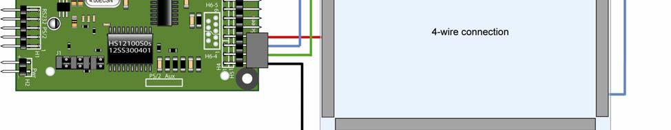


9 Touch Screen Connection Diagrams 9
10 Developed and Supported In-House All TSHARC touch screen controller products are designed to utilize Microchip TSHARC device drivers which are developed, supported and maintained in-house by Microchip engineers. Microchip Technology Inc. does not use third party technical resources to develop, support or maintain any of its software or hardware products. Private Labeled Drivers Private labeled software and hardware licenses are available which may be used to enable various non- TSHARC communication protocols, special functions, application specific utilities or OEM contact information. Contact Microchip for details. TSHARC Controller Chip Solutions Large volume OEM s who have in-house electrical and software engineers on staff may purchase a Microchip Chip Only touch screen controller solution which may be integrated on to their main board. Technical documentation is available from Microchip Technology Inc. to assist you in correctly integrating a chip solution into your product. Please contact Microchip Technology Inc at (414) or Support Services All TSHARC products are 100% developed and supported in house by Microchip technical staff. As a result we have included a broad range of support documentation at including users and setup manuals, device drivers, driver manuals and other software. In addition we have an based support. You may contact us via at: In addition, Microchip also understands that there is often a need for real time technical support. Please contact Microchip via telephone at any point to discuss issues that you may have regarding our products. In the event that you need to contact us via telephone or via our support , please take a minute to identify these items prior to contacting Microchip technical support staff. 1) TSHARC controller part number 2) Information about TSHARC reseller if not purchased directly from Microchip 3) TSHARC chip revision, located on the top of each micro-controller chip 4) Touch Screen type and Manufacturer 5) Communication type 6) TSHARC driver and revision 7) Operating system and service pack releases 8) A brief summary of the problem that you are having 10

11 Notes 11
12 Microchip Technology Inc N. 51st Street, Suite H Brown Deer, WI Main Phone: Main Fax: Microchip, TSHARC and UniWinDriver are trademarks of Microchip Technology Inc. All rights reserved. 12
Setup and Users Manual
 Setup and Users Manual TSHARC Octopus Touch Screen Controller Supports 4-, 5- & 8-Wire Analog Resistive Touch Screens RS-232, PS/2, USB Version 1.6R Document Revision and Copyright Document Name: 04B_TSHARC_Octopus1.6Users090827
Setup and User s Manual TSHARC C-Ray Capacitive Touch Screen Controller Board Supports RS-232 and USB
 Setup and User s Manual TSHARC C-Ray Capacitive Touch Screen Controller Board Supports RS-232 and USB Version 3.3x Document Revision and Copyright Document Name: 08B_TSHARC_C-Ray_Users_Rev3.3x_090827 Document
TSHARC C-Ray Capacitive Touch Screen Controller Board (RS-232 and USB)
") M:\03_Products\TSHARC_Boards\TSHARC_C-Ray\C_Ray_3.3A\C-Ray_3.3_UsersManual\08B_TSHARC_C-Ray_Users_Rev3.3x_081121.doc Setup and User s Manual TSHARC C-Ray Capacitive Touch Screen Controller Board (RS-232
M:\03_Products\TSHARC_Boards\TSHARC_C-Ray\C_Ray_3.3A\C-Ray_3.3_UsersManual\08B_TSHARC_C-Ray_Users_Rev3.3x_081121.doc Setup and User s Manual TSHARC C-Ray Capacitive Touch Screen Controller Board (RS-232
TSHARC-C2 Surface Capacitive Touch Screen Microcontroller Application Guide Ver. 3.3
 H:\PigData\MasterBinders\03_Products\TSHARC_Chips\TSHARC_C0_Chip\TSHARC_C0_ApplicationManual\TS HARC-C2_Chip_App_Guide3.3B090827.doc TSHARC-C2 Surface Capacitive Touch Screen Microcontroller Application
Setup and Users Manual
 \04_TSHARC-Octopus\UsersManual\OctopusRev1.6\04B_TSHARC_Octopus1.6Users040419.doc Setup and Users Manual TSHARC Octopus RS-232, PS/2, USB Touch Screen Controller Version 1.6 TSHARC Octopus Mechanical Specification
Touch Screen. Bergquist. User s Guide. Set-Up and Use of Bergquist 5-Wire Controller USB, RS-232, & PS/2 TOUCH SCREEN CONTROLLER FEATURES
 Bergquist Touch Screen User s Guide USB, RS-232, & PS/2 TOUCH SCREEN CONTROLLER Set-Up and Use of Bergquist 5-Wire Controller FEATURES Jumper-selectable RS-232, PS/2 and USB communications options 5-Wire
Trimble S6 and SPS700 Total Station Firmware
 Trimble S6 and SPS700 Total Station Firmware Release Notes Introduction Upgrading from a previous version Using Trimble S6/SPS700 firmware with other Trimble products New features/enha ncements Changes
PCMCIA Flash Card User Guide
 R R PCMCIA Flash Card User Guide For the CoreBuilder 3500 System Introduction The CoreBuilder 3500 PCMCIA Flash Card is a 20 MB flash card that you can use to save your system software. When you have saved
Release Information. Revision History. Version: build 018 Release Date: 23 rd November 2011
 Version: 02.00.2 build 018 Release Date: 23 rd November 2011 Release Date Version 02.00.2 Build 018 23 rd November 2011 Release Information Release Type: General Availability Supported Cyberoam Versions:
OPERATIONS MANUAL PCM-I/O48
 OPERATIONS MANUAL PCM-I/O48 NOTE: This manual has been designed and created for use as part of the WinSystems Technical Manuals CD and/or the WinSystems website. If this manual or any portion of the manual
Bluetooth 4.0 USB Adapter Model
 Bluetooth 4.0 USB Adapter Model 604002 Windows OS 8.1/10: Drivers auto-install 7/Vista/XP: Drivers are required Quick Start Guide Download drivers at cablematters.com/downloads Email: support@cablematters.com
Upgrading BMDM and BMRG Software and MPM, BDS and DCM Firmware
 Upgrading BMDM and BMRG Software and MPM, BDS and DCM Firmware 990 South Rogers Circle, Suite 11 Boca Raton, FL 33487 Tel: 561-997-2299 Fax: 561-997-5588 www.alber.com 1. Warranty and Limitation of Liability
THECHARGEHUB.COM. User Manual. For Square & Round Models
 THECHARGEHUB.COM User Manual For Square & Round Models User Manual THECHARGEHUB.COM 7-Port USB Universal Charging Station Table of Contents General Safety Information...2 Care and Maintenance...3 Introduction...4
RELEASE NOTES TRIMBLE REALWORKS SOFTWARE VERSION System requirements New Features and Changes
 RELEASE NOTES TRIMBLE REALWORKS SOFTWARE VERSION 9.0.1.313 System requirements New Features and Changes Trimble Navigation Ltd, 10368 Westmoor Drive, Westminster, CO 80021, USA 2014, Trimble Navigation
E2K-F. Flat Capacitive Sensor with a Thickness of Only 10 mm. Flat Proximity Sensor. Ordering Information. Sensors [Refer to Dimensions on page 4.
 Flat Proximity Sensor EK-F CSM_EK-F_DS_E Flat Capacitive Sensor with a Thickness of Only mm Flat Sensor with excellent space efficiency. (Model with built-in Amplifier is only mm thick.) Direct mounting
FTC-200 X-ray Tube Controller Users Manual
 Tubes FTC-200 X-ray Tube Controller TUB-MAN-2101 Rev. A 09/09/2009TTUB Table of Contents List of Tables...3 List of Figures...3 Introduction...3 Manual Set...3 About this Manual...4 X-Ray Safety Information...4
CM68 4 Channel NTSC/PAL Video Decoder
 CM68 4 Channel NTSC/PAL Video Decoder Technical Reference Guide PCB Rev 1.0 www.soc-robotics.com Copyright 2009. SOC Robotics, Inc. 1 Manual Rev 0.90 Warranty Statement SOC Robotics warrants that the Product
Demo Kit Quick Start Guide
 Near Field Imaging (NFI) Projected Capacitive Touch Screen Systems Read and understand all safety information contained in this document before using this product. Introduction This is intended to help
CAP1114. Multiple Channel Capacitive Touch Sensor and LED Driver PRODUCT FEATURES PRODUCT PREVIEW
 CAP1114 Multiple Channel Capacitive Touch Sensor and LED Driver PRODUCT FEATURES Data Brief General Description The CAP1114, which incorporates SMSC s RightTouch TM1 technology, is a multiple channel Capacitive
MPP200 User s Manual
 2011 Visionary Solutions, Inc. All rights reserved. Please visit the support section of our website at www.vsicam.com for manuals, other documentation, and software downloads. Visionary Solutions, Inc.
Brushless DC Motor Controller Specification Assembly 025A0053
 Brushless DC Motor Controller Specification Assembly 025A0053 600A0053 Rev. 2 July 28, 2004 025A0053 Brushless DC Motor Controller Data Sheet Page 1 Revision History Date Rev Description By 5/15/04 1 Initial
Thermocouple Input Module
 User Manual for the HE150THM180 Thermocouple Input Module Fifth Edition April 01, 1998 MAN0004-05 PREFACE 4-01-98 PAGE 2 PREFACE This manual explains how to use Horner APG s Thermocouple Input module for
PRODUCT CONTENTS... 3 II. REQUIRED MATERIALS... 3 III. OVERVIEW... 3 IV. BENCH LAYOUT...
 IR-510 Bench 2012 Infrared Industries, Inc. 25590 Seaboard Lane Hayward, CA 94545 Toll-free phone 800.344.0321 Phone 510.782.8100 Fax 510.782.8101 www.infraredindustries.com Table of Contents I. PRODUCT
3M SlimLine 85ohm Cable Assembly
 Product Specifications May 2017 78-5102-0240-7, Rev B Scope This document summarizes test methods, test conditions, and product performance requirements for 3M SlimLine 85ohm Cable Assembly. Reference
Mile Terms of Use. Effective Date: February, Version 1.1 Feb 2018 [ Mile ] Mileico.com
![Mile Terms of Use. Effective Date: February, Version 1.1 Feb 2018 [ Mile ] Mileico.com](/thumbs/86/94427576.jpg "Mile Terms of Use. Effective Date: February, Version 1.1 Feb 2018 [ Mile ] Mileico.com") Mile Terms of Use Effective Date: February, 2018 Version 1.1 Feb 2018 [ Mile ] Overview The following are the terms of an agreement between you and MILE. By accessing, or using this Web site, you acknowledge
Mile Terms of Use Effective Date: February, 2018 Version 1.1 Feb 2018 [ Mile ] Overview The following are the terms of an agreement between you and MILE. By accessing, or using this Web site, you acknowledge
FES LCD Display Version 1.1
 FES LCD Display Version 1.1 LZ design d.o.o., Brod 3D, 1370 Logatec, Slovenia tel +386 59 948 898 info@lzdesign.si www.front-electric-sustainer.com Table of Content 1. Important notices... 3 1.1 Limited
USB3740. High Speed Switch for Mobile and Portable Applications USB3740 PRODUCT FEATURES DATASHEET. USB3740 Block Diagram
 USB3740 High Speed Switch for Mobile and Portable Applications PRODUCT FEATURES High Speed USB Mux for multiplexing the USB lanes between different functions Switch the USB connector between two different
HP Worldwide Limited Warranty and Technical Support
 HP Worldwide Limited Warranty and Technical Support HP Hardware Limited Warranty Limited Warranty Period This HP Hardware Limited Warranty gives you, the customer, express limited warranty rights from
3M Sensored Cable Accessories for Underground Medium Voltage Distribution System
 3M Sensored Cable Accessories for Underground Medium Voltage Distribution System 3M Electronics & Energy Business 1 Introduction The focus on enhancing reliability and efficiency of the power grid has
SonicWALL CDP 2.1 Agent Tool User's Guide
 COMPREHENSIVE INTERNET SECURITY b SonicWALL CDP Series Appliances SonicWALL CDP 2.1 Agent Tool User's Guide SonicWALL CDP Agent Tool User s Guide Version 2.0 SonicWALL, Inc. 1143 Borregas Avenue Sunnyvale,
Trimble R/5000 Series GPS Receivers Release Notes
 Trimble R/5000 Series GPS Receivers Release Notes Introduction New Features and Changes Upgrade Procedure Version 2.21 Revision A October 2004 Corporate Office Trimble Navigation Limited 5475 Kellenburger
Bluetooth USB Adapter TALUS. User Guide
 Bluetooth USB Adapter TALUS User Guide Revision 0.1 1 User Guide for the TALUS Revision 1.0.1 Firmware version 1.0.X Printed in Korea Copyright Copyright 2008, SystemBase Co., Ltd. All rights reserved.
Made in U.S.A. 1
 Made in U.S.A. www.smartavi.com 1 1-800-AVI-2131 TABLE OF CONTENTS INTRODUCTION & FEATURES 2 Getting Started and Installation 3 Start-Up 4 Managing Streams and Environment 5 Frequently Asked Questions
3M Constant Monitors WSMONITOR1, WSMONITOR 2, WSMONITOR3
 3M Constant Monitors WSMONITOR1, WSMONITOR 2, WSMONITOR3 User s Guide WSMONITOR1 WSMONITOR2 WSMONITOR3 Table of Contents Section Page SAFETY INFORMATION...3 Introduction...5 Installation...6 Operation...9
ACLD Channel Opto-isolated Digital Input Board
 ACLD-9182 16 Channel Opto-isolated Digital Input Board @ Copyright 1996 All Rights Reserved. Manual edition 01, January 1996 The information in this document is subject to change without prior notice in
quick setup Plug the keyboard into your computer. For: Windows Linux Mac OS X 10.3 or earlier For: Mac OS X 10.4 or later
 Dvorak Pro Keyboard (FK207QPC) quick setup 1 Plug the keyboard into your computer. 2 For: Windows Linux Mac OS X 10.3 or earlier Setup is complete. For more information, please turn to page 3. For: Mac
End User License Agreement
 End User License Agreement Kyocera International, Inc. ( Kyocera ) End User License Agreement. CAREFULLY READ THE FOLLOWING TERMS AND CONDITIONS ( AGREEMENT ) BEFORE USING OR OTHERWISE ACCESSING THE SOFTWARE
Analog Resistive Touch Screen Controller TSC-45/RSA-E User s Guide
 Analog Resistive Touch Screen Controller TSC-45/RSA-E User s Guide Table of Contents 1. Product Overview... 2 1-1. Products Applicable... 2 1-2. Overview... 2 1-3. Peripheral Composition Overview... 3
Wasp Embedded Controller
 Wasp Embedded Controller Wasp16/32/64 Hardware Reference Guide PCB Rev 1.0 WASP16 WASP32 WASP64 MC433 Hardware Reference Guide Manual Revision 0.85 Table of Contents Warranty Statement...2 1.0 Introduction....4
Piccola Smart Box Member of Modul MAS family
 Piccola Smart Box Member of Modul MAS family Pag. 1 of 6 Piccola Smart Box Rev.1.1 All Rights Reserved. No part of this document may be photocopied, reproduced, stored in a retrieval system, or transmitted,
USB 3.0 Spectra
 USB 3.0 Spectra 3001-15 1-Port USB 3.0 15m Active Extension Cable User Guide Thank you for purchasing the Icron USB 3.0 Spectra 3001-15. Please read this guide thoroughly. This document applies to Part
Customer Support: For more information or support, please visit or at Product Release Information...
 Product Release Information Product: Cyberoam Release Number: 9.3.0 build 5 Release Date: 19th July 2006 Compatible versions: 9.2.0 build 2 Upgrade Mode: Manual 1 Important note Upgrade removes all the
EMC2113. RPM-Based Fan Controller with Multiple Temperature Zones & Hardware Thermal Shutdown PRODUCT FEATURES. General Description.
 EMC2113 RPM-Based Fan Controller with Multiple Temperature Zones & Hardware Thermal Shutdown PRODUCT FEATURES Data Brief General Description The EMC2113 is an SMBus compliant fan controller. The fan driver
USB Server User Manual
 1 Copyright Notice Copyright Incorporated 2009. All rights reserved. Disclaimer Incorporated shall not be liable for technical or editorial errors or omissions contained herein; nor for incidental or consequential
3M Twin Axial Cable Assembly for Medical Electronics Packaging
 3M Electronic Solutions Division 3M Twin Axial Cable Assembly for Medical Electronics Packaging Charlie Staley MEPTEC September 2012 Risers Cards and Extender Cables Sometimes system mechanical configurations
QUICK START GUIDE. 1. How to register your Camera to Hubble account A. Setting Up the Camera - can be connected via WiFi or LAN
 MODEL: FOCUS72 FOCUS72-2 FOCUS72-3 FOCUS72-4 FOCUS72-W FOCUS72-W2 FOCUS72-W3 FOCUS72-W4 QUICK START GUIDE For a full explanation of all features and instructions, please refer to the User s Guide. (available
CX Recorder. User Guide. Version 1.0 February 8, Copyright 2010 SENSR LLC. All Rights Reserved. R V1.0
 CX Recorder User Guide Version 1.0 February 8, 2010 Copyright 2010 SENSR LLC. All Rights Reserved. R001-418-V1.0 TABLE OF CONTENTS 1 PREAMBLE 3 1.1 Software License Agreement 3 2 INSTALLING CXRECORDER
MEC-COM-M114. User s Manual
 MEC-COM-M114 Mini PCI-e 4-port RS-232 serial board with power input User s Manual Third Edition, February 2014 2014 Cervoz Co., Ltd. All rights reserved. Reproduction without permission is prohibited Mini
URC Light Sensor SEN-LITE for use with MRX units containing sensor ports
 URC Light Sensor SEN-LITE for use with MRX units containing sensor ports URC Light Sensor SEN-LITE 2014 Universal Remote Control, Inc. The information in this Owner s Manual is copyright protected. No
PMDX-103. Parallel Port Isolator Board. User s Manual. Document Revision: 1.2 Date: 20 February 2007 PCB Revision: PCB-447B
 PMDX-103 Parallel Port Isolator Board User s Manual Date: 20 February 2007 PMDX Web: http://www.pmdx.com 9704-D Gunston Cove Rd Phone: +1 (703) 372-2975 Lorton, VA 22079-2366 USA FAX: +1 (703) 372-2977
vippaq Main App. User Guide
 vippaq Main App. User Guide Edition 1d July 2008 Contents 1 INTRODUCTION 3 1.1 3 2 SYSTEM PREPARATION 4 2.1.1 Measuring Head Connection 5 2.1.2 Position the Measuring Heads 5 2.1.3 Start Job 5 3 MEASURE
Smart Ocean Smart Rim Lock Data Sheet
 Smart Ocean Smart Rim Lock Data Sheet Release: Version 1.0 Date: 12-September-2016 Chengdu Smart Ocean Technology Co. Ltd. Room 2205, Block 2, 1st Phase, Chengdu Center No. 138, 2nd Tianfu Street, Tianfu
CM Mpixel CMOS Imaging Camera
 CM130 1.3Mpixel CMOS Imaging Camera Technical Reference Guide PCB Rev 1.0 www.soc-robotics.com Copyright 2009. SOC Robotics, Inc. 1 Manual Rev 0.90 Warranty Statement SOC Robotics warrants that the Product
SATA II HDD Canister KISS DA 435 Quick Reference Guide
 SATA II HDD Canister KISS DA 435 Quick Reference Guide If it s embedded, it s Kontron 1. Table of Contents SATA II HDD Canister KISS DA 435 1. Table of Contents 1. Table of Contents... 1 2. Important Information...
Sierra 80 Volt Brushless DC Motor Controller Product Specification
 Sierra 80 Volt Brushless DC Motor Controller Product Specification Assembly 025F0135 600A0588 Rev. B January 29, 2010 025F0135 Brushless DC Motor Controller Page 1 Revision History ECN # Date Rev Description
H-UC232S USB Serial Converter
 H-UC232S USB Serial Converter FCC Warning This equipment has been tested and found to comply with the regulations for a Class B digital device, pursuant to Part 15 of the FCC Rules. These limits are designed
Instruction Sheet. PCS Series. Fiber\Cable Management Spool
 Instruction Sheet PCS Series Fiber\Cable Management Spool THANK YOU! Thank you for purchasing the PCS Series Fiber\Cabling Management Spool. Please read these instructions thoroughly before installing
EVB-USB2640 Evaluation Board Revision A
 Copyright 2008 SMSC or its subsidiaries. All rights reserved. Circuit diagrams and other information relating to SMSC products are included as a means of illustrating typical applications. Consequently,
E2KQ-X. Fluororesin-coated Capacitive Sensor with Sensitivity Adjuster. Chemical-resistant Proximity Sensor. Ordering Information
 Chemical-resistant Proximity Sensor E2KQ-X CSM_E2KQ-X_DS_E_4_3 Fluororesin-coated Capacitive Sensor with Sensitivity Adjuster Excellent resistance against chemicals and oil with fluororesincoated case.
MEC-SAT-M002. User s Manual
 MEC-SAT-M002 Mini PCI-e 2-port Serial ATA III board User s Manual Third Edition, February 2014 2014 Cervoz Co., Ltd. All rights reserved. Reproduction without permission is prohibited Mini PCI-e SATA Card
MULTIPLEXER MX4. Operation and Installation Manual. Pacific Micro Systems
 MULTIPLEXER MX4 Operation and Installation Manual Pacific Micro Systems LIMITED WARRANTY Pacific Micro Systems warrants its products to be free from defects in materials and workmanship for a period of
Shimadzu LabSolutions Connector Plugin
 Diablo EZReporter 4.0 Shimadzu LabSolutions Connector Plugin Copyright 2016, Diablo Analytical, Inc. Diablo Analytical EZReporter Software EZReporter 4.0 Shimadzu LabSolutions Connector Plugin Copyright
PowerRING Qi DUAL WIRELESS CHARGING RECEIVER
 PowerRING Qi DUAL WIRELESS CHARGING RECEIVER Please register online www.minibatt.com/register Qi-compatible USER MANUAL minibatt PowerRING.indd 1 25/4/16 12:42 Thank you for selecting minibatt products.
Epson Professional Imaging
 Epson Professional Imaging Epson Gemini 2 to Epson Gemini K3 Upgrade Program Epson Gemini 2 Customer Information All Fields Required Company Name Gemini K3 Ship To Information Ship To Location Use Same
Product Release Information
 Product Release Information Product: Cyberoam Release Number: 9.4.1 build 2 Release Date: 20 th March, 2007 Compatible versions: 9.4.1. build 0 Upgrade: Auto Upgrade Customer Support: For more information
10 Degree of Freedom IMU Sensor +-16G, dps, +-8Gauss, hPa
 DOF10W 10 Degree of Freedom IMU Sensor +-16G, +-2000 dps, +-8Gauss, 350-700hPa Technical Reference Manual PCB Rev 1.0 www.soc-robotics.com Copyright 2011. SOC Robotics, Inc. 1 Manual Rev 0.9 Warranty Statement
TERMS & CONDITIONS. Complied with GDPR rules and regulation CONDITIONS OF USE PROPRIETARY RIGHTS AND ACCEPTABLE USE OF CONTENT
 TERMS & CONDITIONS www.karnevalkings.com (the "Site") is a website and online service owned and operated by the ViisTek Media group of companies (collectively known as "Karnevalkings.com", "we," "group",
FastForward TM User Guide
 Let s play follow the leader! FastForward TM User Guide LG G4010 and G4050 Series Phones Welcome Thank you for purchasing Cingular s FastForward. Now you can easily forward incoming calls made to your
Ludlum Lumic Data Logger Software Manual Version 1.1.xx
 Ludlum Lumic Data Logger Software Manual Version 1.1.xx Ludlum Lumic Data Logger Software Manual Version 1.1.xx Contents Introduction... 1 Software License Agreement... 2 Getting Started... 5 Minimum
CAN Fiber Optic Modem
 User Manual for the HE200CFM100 CAN Fiber Optic Modem Second Edition 17 September 1999 MAN0007-02 PREFACE 17 SEPT 1999 PAGE 3 PREFACE This manual explains how to use the Horner APG s CAN Fiber Optic Modem.
FastForward User Guide
 Let s play follow the leader! FastForward User Guide Nokia 3100, 3200, 6100, 6200 & 6800 Series Phones Welcome Thank you for purchasing Cingular s FastForward. Now you can easily forward incoming calls
EASON TECHNOLOGY. IO8 & IO24 Break-Out Module
 EASON TECHNOLOGY IO8 & IO24 Break-Out Module p/n 50-00180-01 Revision1.2 Eason Technology, Inc. 7975 Cameron Dr. Bldg 300 Windsor, CA 95492 Phone (707) 837-0120 FAX (707) 837-2742 http://www.eason.com
FLAP indicator. Installation manual Version 1.10
 FLAP indicator Installation manual Version 1.10 LXNAV d.o.o. Kidričeva 24, 3000 Celje, Slovenia tel +386 592 33 400 fax +386 599 33 522 info@lxnav.com www.lxnav.com 1 Important Notices... 3 1.1 Limited
BD027-14E Low-Voltage Nanopower Digital Switch for Medical Devices
 BD27-14E Low-Voltage Nanopower Digital Switch for Medical Devices Key Features Low Voltage Operation to.9 V Power Consumption 45 nw Maximum at.9 V Digital Switch Output Precise Detection of Low Magnetic
S82S (3/7.5-W Models)
") Switch Mode Power Supply (3/7.5-W Models) CSM DS_E_4_3 Miniature DIN Rail Mounting DC-DC Power Supplies 65 mm depth enables mounting onto control panels with 100 mm depth. Inputs: 10.2 to 27.6 VDC (DC
Switch Mode Power Supply (3/7.5-W Models) CSM DS_E_4_3 Miniature DIN Rail Mounting DC-DC Power Supplies 65 mm depth enables mounting onto control panels with 100 mm depth. Inputs: 10.2 to 27.6 VDC (DC
BD020 Nanopower Medical Magnetic Sensor
 Datasheet BD020 Nanopower Medical Magnetic Sensor Key Features Ultraminiature 1.1 mm x 1.1 mm x 0.45 mm ULLGA package Solid-State Reliability Precise Detection of Low Magnetic Fields Low Voltage Operation
Analog Interface Unit Operation Manual
 Analog Interface Analog Interface Unit Operation Manual WARRANTY Accurate Technology, Inc. warrants the product against defective parts and workmanship for 1 year commencing from the date of original purchase.
PSA200 User s Manual
 2011 Visionary Solutions, Inc. All rights reserved. Please visit the support section of our website at www.vsicam.com for manuals, other documentation, and software downloads. Visionary Solutions, Inc.
ZXDSL 931DII User Manual
 Document version: 2009-8-20 R1.0 Copyright 2009 ZTE Corporation All rights reserved. No part of this documentation may be excerpted, reproduced, translated, annotated or duplicated, in any form or by any
AnalogBridge Analog transmission system
 AnalogBridge Analog transmission system Enclosure showing RTU Module and optional Power supply, External Relay User Guide Revision 1.4 Wireless Solutions at Work www.orbitcoms.com Page 1 Orbit Communications
E2K-F. Flat Capacitive Sensor with a Thickness of Only 10 mm. Flat Proximity Sensor. Ordering Information. Sensors [Refer to Dimensions on page 4.
 Flat Proximity Sensor EK-F CSM_EK-F_DS_E Flat Capacitive Sensor with a Thickness of Only mm Flat Sensor with excellent space efficiency. (Model with built-in Amplifier is only mm thick.) Direct mounting
3M Textool Open-Top Test and Burn-In Sockets for Ball Grid Array Packages
 3M Textool Open-Top Test and Burn-In Sockets for Ball Grid Array Packages 3Innovation Table of Contents Product Advantages...1 Durability...1 Reliability...2 Micro-Wiping and Solder Ball Deformation...3
Touch Screen. ClearTek II Capacitive. Product Highlights
 ClearTek II Capacitive Touch Screen Product Highlights Excellent light transmission of 91.5% (+/-1.5%) provides vibrant optical characteristics with optimal anti-glare properties Resilient top coat provides
SVP48 SURGE VOLTAGE PROTECTOR INSTRUCTION MANUAL
 SVP48 SURGE VOLTAGE PROTECTOR INSTRUCTION MANUAL REVISION: 3/03 COPYRIGHT (c) 1995-2003 CAMPBELL SCIENTIFIC, INC. This is a blank page. Warranty and Assistance The SVP48 SURGE VOLTAGE PROTECTOR is warranted
DX-C USER GUIDE
 PC/Mac USB File Transfer Adapter DX-C114200 USER GUIDE 2 3 Dynex DX-C114200 PC/Mac USB File Transfer Adapter Contents Important safety instructions...3 Introduction...4 Features...5 Package Contents...5
CL-8. User Guide and Technical Information
 CL- User Guide and Technical Information E7556 State Highway 23 and 33 Reedsburg, WI USA 53959 +1 (60) 524-0625 fax: +1 (60) 524-0655 Toll-Free: (00) 505-0625 www.sounddevices.com support@sounddevices.com
User Guide. Single-Link DVI Fiber Optic Extender DVI-7315
 User Guide Single-Link DVI Fiber Optic Extender DVI-7315 Table of Contents Section Page Product Safety...1 1. Introduction................................... 2 2. Specifications..................................
Electroformed Probe Pins XP3A
 New Product Electroformed Probe Pins Electroplated Probe Pins for High Reliability The Probe Pin that is made of only one part. The flat structure helps you reduce the pin pitch in comparison with standard
3M Quick Connect System (QCS) 2814
 2814") Communication Markets Division 3M Quick Connect System (QCS) 2814 Designed for your broadband network The 3M Quick Connect System 2814 is a terminal/cross-connect system featuring integrated protection
Communication Markets Division 3M Quick Connect System (QCS) 2814 Designed for your broadband network The 3M Quick Connect System 2814 is a terminal/cross-connect system featuring integrated protection
The Next-generation Sensor Networking Units That Revolutionize the Workplace from Introduction and Startup though Operation. Fiber Units.
 Sensor Communications Unit CSM DS_E_1_1 The Next-generation Sensor Networking Units That Revolutionize the Workplace from Introduction and Startup though Operation Low initial cost achieved by distributed
Industrial Semi-Metal USB
 Industrial Semi-Metal USB Generation 3L HERMIT-C Series Product Specification INDUSTRIAL Semi-Metal USB Flash Disk Generation 3L Version 01V0 Document No. 100-xMUFD-HCT3L December, 2015 APRO CO., LTD.
Instruction Sheet ICLS-COOL TM. Quiet-Cool Series Closet Cooler ICLS-COOL1 ICLS-COOL2
 Instruction Sheet ICLS-COOL TM Quiet-Cool Series Closet Cooler (REAR) (REAR) THANK YOU TM Thank you for purchasing the Quiet Cool Series ICLS-COOL Closet Cooler. Please read these instructions thoroughly
FCC Warning. CE Mark Warning. VCCI Mark Warning
 FCC Warning This equipment has been tested and found to comply with the regulations for a Class B digital device, pursuant to Part 15 of the FCC Rules. These limits are designed to provide reasonable protection
MyCreditChain Terms of Use
 MyCreditChain Terms of Use Date: February 1, 2018 Overview The following are the terms of an agreement between you and MYCREDITCHAIN. By accessing, or using this Web site, you acknowledge that you have
Matias Wireless Folding Keyboard for Mac US Layout (FK304) quick setup. Opening & closing the keyboard
 quick setup. Opening & closing the keyboard") Matias Wireless Folding Keyboard for Mac US Layout (FK304) quick setup 1 Opening & closing the keyboard To open, slide the open switch down. To close, fold and press the two ends together. REMEMBER to
Matias Wireless Folding Keyboard for Mac US Layout (FK304) quick setup 1 Opening & closing the keyboard To open, slide the open switch down. To close, fold and press the two ends together. REMEMBER to
Single Cell Battery Power Solution
 Single Cell Battery Power Solution Input 5V DC Output 2.80.. 4.28V (dependent on charge state of battery) Current limited to 500mA max. Devices TPS2113A Autoswitching Power MUX TPD4S012 4-Channel USB ESD
American Power Design, Inc.
 FEATURES 4 Customer Selects Output 4 Single Outputs to or 6000 Vdc 4 Dual Outputs to / 3000 Vdc 4 High Reliability 4 Industry Standard Pinouts 4 Wide Temperature Range (20 to 85 C) 4 60 khz Switching Frequency
Don t plug me in just yet.
 Easy Transfer Cable for Windows 7 Don t plug me in just yet. We need to do a few things first to get your computers ready to transfer your files and user accounts. Quick Start Guide F5U279 i 1 Prepare
StandUP WIRELESS CHARGER
 StandUP WIRELESS CHARGER Please register online www.minibatt.com/register Qi-compatible USER MANUAL minibatt StandUP.indd 1 25/4/16 12:21 Thank you for selecting minibatt products. Thank you for purchasing
Vocia. Page Active Relay Module (PARM-1) Operation Manual
 Operation Manual") Vocia Page Active Relay Module (PARM-1) Operation Manual Biamp System 9300 SW Gemini Drive, Beaverton, OR 97008 U.S.A. (503) 641-7287 www.biamp.com table of contents Vocia Page Active Relay Module (PARM-1)
Vocia Page Active Relay Module (PARM-1) Operation Manual Biamp System 9300 SW Gemini Drive, Beaverton, OR 97008 U.S.A. (503) 641-7287 www.biamp.com table of contents Vocia Page Active Relay Module (PARM-1)