ibox-280 User Manual
|
|
|
- Doreen Greene
- 5 years ago
- Views:
Transcription
1 ibox-280 User Manual
2 Version.0 Published February 204 Copyright 204 ASRock Inc. All rights reserved. Copyright Notice: No part of this documentation may be reproduced, transcribed, transmitted, or translated in any language, in any form or by any means, except duplication of documentation by the purchaser for backup purpose, without written consent of ASRock Inc. Products and corporate names appearing in this documentation may or may not be registered trademarks or copyrights of their respective companies, and are used only for identification or explanation and to the owners benefit, without intent to infringe. Disclaimer: Specifications and information contained in this documentation are furnished for informational use only and subject to change without notice, and should not be constructed as a commitment by ASRock. ASRock assumes no responsibility for any errors or omissions that may appear in this documentation. With respect to the contents of this documentation, ASRock does not provide warranty of any kind, either expressed or implied, including but not limited to the implied warranties or conditions of merchantability or fitness for a particular purpose. In no event shall ASRock, its directors, officers, employees, or agents be liable for any indirect, special, incidental, or consequential damages (including damages for loss of profits, loss of business, loss of data, interruption of business and the like), even if ASRock has been advised of the possibility of such damages arising from any defect or error in the documentation or product. This device complies with Part 5 of the FCC Rules. Operation is subject to the following two conditions: () this device may not cause harmful interference, and (2) this device must accept any interference received, including interference that may cause undesired operation. CALIFORNIA, USA ONLY The Lithium battery adopted on this motherboard contains Perchlorate, a toxic substance controlled in Perchlorate Best Management Practices (BMP) regulations passed by the California Legislature. When you discard the Lithium battery in California, USA, please follow the related regulations in advance. Perchlorate Material-special handling may apply, see perchlorate ASRock s Website:
3 AUSTRALIA ONLY Our goods come with guarantees that cannot be excluded under the Australian Consumer Law. You are entitled to a replacement or refund for a major failure and compensation for any other reasonably foreseeable loss or damage caused by our goods. You are also entitled to have the goods repaired or replaced if the goods fail to be of acceptable quality and the failure does not amount to a major failure. If you require assistance please call ASRock Tel : ext.23 (Standard International call charges apply) The terms HDMI and HDMI High-Definition Multimedia Interface, and the HDMI logo are trademarks or registered trademarks of HDMI Licensing LLC in the United States and other countries.
4 Replaceable batteries CAUTION RISK OF EXPLOSION IF BATTERY IS REPLACED BY AN INCORRECT TYPE. DISPOSE OF USED BATTERIES ACCORDING TO THE INSTRUCTIONS Contact Information If you need to contact ASRock or want to know more about ASRock, you re welcome to visit ASRock s website at or you may contact your dealer for further information. ASRock Incorporation 6F., No.37, Sec. 2, Jhongyang S. Rd., Beitou District, Taipei City 2, Taiwan (R.O.C.)
5 Contents Chapter Introduction. Package Contents.2 Product Specifications 2 Chapter 2 Product Overview 3 2. Inside View Front View Rear View 5 Chapter 3 Hardware Installation 6 3. Removing the Chassis Top Cover Installing Memory Modules (SO-DIMM) Installing the Hard Drive 9 Chapter 4 Motherboard 4 4. Motherboard Layout Motherboard Specifications Jumpers Setup Onboard Headers and Connectors Expansion Slots (PCI Express, mini-pcie and mini-pcie/ 27 mini-sata Slots) 27
6 ibox Chapter Introduction Thank you for purchasing ibox-280, a reliable embedded box PC produced under ASRock s consistently stringent quality control. It delivers excellent performance with robust design conforming to ASRock s commitment to quality and endurance. Because the hardware specifications might be updated, the content of this documentation will be subject to change without notice. In case any modifications of this documentation occur, the updated version will be available on ASRock s website without further notice. If you require technical support related to this product, please visit our website for specific information about the model you are using. ASRock s Website: The illustrations shown in this manual are examples only, the actual system may differ slightly.. Package Contents ibox-280 DN2800MT (pre-installed motherboard) x SATA to Power Cable Rubber Pads 4 x HDD Screws (M3x3) msata/minipcie Screws (M2x3) Wall Mount Bracket (optional) Power Adapter User Manual If any items are missing or appear damaged, contact your authorized dealer.
7 ibox.2 Product Specifications ibox-280 Processor System CPU Intel Cedarview Atom N2800 Dual core.86ghz TDP 6.5W Memory 2 x DDR3-066MHz SO-DIMM up to 4 GB Chipset Intel NM0 Graphic Intel GMA3650 LAN Chipset Intel 82574L Watch Dog 256 Segments,0,,2, 255sec/min Rear I/O Serial Port 2 x 232 port USB 6 USB 2.0 ports LAN RJ45 Port for Gbe Vedio output x VGA, x HDMI Audio Mic-in/ Line out Expansion x mini PCIe / x msata Storage Type x 2.5" HDD/ SSD OS Support Window 7 / Linux Certifications CE, FCC, Class A Environmental Operating Temp 0 C~50 C Storage Temp -20 C~80 C Humidity 0%~90% Mechanical Material Top cover -aluminum extrusion/ Base- metal Dimension 200 x 200 x 35mm Weight.8 Kg Mounting mounting bracket ( optional) * For detailed product information, please visit our website: 2

8 Chapter 2 Product Overview This chapter provides diagrams showing the location of important components of the ibox Inside View Rear Panel HDD mounting bracket M/B SO-DIMM sockets CPU Heatsink Front Panel 3

9 ibox 2.2 Front View No. Description 2 x USB 2.0 Ports 2 2 x COM Ports 3 Power LED 4 HDD LED 5 On-/off Switch Status LED Definitions Power LED Status Solid Green Off HDD Status LED Status Red Off Description Power on Power off Description HDD installed HDD uninstalled 4
 5 Microphone (Pink) * There are two LEDs on each LAN port. Please refer to the table below for the LAN port LED indications.")
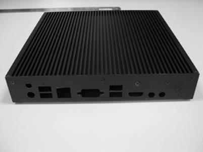
10 2.3 Rear View No. Description No. Description Antenna Port 6 Line out (Lime) 2 LAN RJ-45 Port (LAN)* 7 HDMI Port (HDMI) 3 VGA Port (VGA) 8 4 x USB 2.0 Ports 4 Antenna Port 9 DC Jack (DC_JACK) 5 Microphone (Pink) * There are two LEDs on each LAN port. Please refer to the table below for the LAN port LED indications. ACT/LINK LED SPEED LED LAN Port Activity / Link LED Speed LED Status Description Status Description Off No Link Off 0Mbps connection Off Data Activity Orange 00Mbps connection On Link Green Gbps connection 5
11 Chapter 3 Hardware Installation This chapter provides step-by-step procedures on how to install components. Installation Procedures Removing the chassis top cover Installing the memory modules (SO-DIMM) Installing the 2.5-inch hard drive Replacing the chassis top cover After making sure that you have properly connected the power supply and all the necessary peripherals, power on the system. 6
12 ibox 3. Removing the Chassis Top Cover. Remove the three screws on the front panel. 2. Remove the three screws on the rear panel. 3. Remove the four screws in the bottom case. 4. Lift up and remove the top cover
13 3.2 Installing Memory Modules (SO-DIMM) This motherboard provides two 204-pin DDR3 (Double Data Rate 3) SO-DIMM slots. Please install the SO-DIMM module into the DDR3_A2 for the first priority. It is not allowed to install a DDR or DDR2 memory module into a DDR3 slot; otherwise, this motherboard and SO-DIMM may be damaged. The SO-DIMM only fits in one correct orientation. It will cause permanent damage to the motherboard and the SO-DIMM if you force the SO-DIMM into the slot at incorrect orientation. 2 8


14 ibox 3.3 Installing the Hard Drive Removing HDD Mounting Bracket. Remove the four screws that secure the HDD mounting bracket to the chassis. 2. Lift up and remove the HDD mounting bracket. 9
15 Installing a 2.5-inch Hard Drive. Place the HDD into the HDD mounting bracket with the printed circuit board side facing down. Carefully align the mounting holes in the hard drive and the HDD carrier. 2. Secure the hard drive into the place using the four screws. 3. Attach one end of the SATA to Power Cable to the hard drive. 4. Secure the HDD mounting bracket to the chassis using the four screws. 5. Attach the SATA data cable and power cable to the motherboard SATA_PWR SATAII_ 0

16 ibox 3.4 Replacing the Top Cover. Replace the top cover, making sure the mark on the top cover is aligned with the HDD mounting bracket. 2. Secure the three screws on the front panel. 3. Secure the three screws on the rear panel. 4. Secure the four screws at the bottom.


17
18 ibox 3.5 Using the Wall Mount Bracket. Attach the Wall Mount Bracket to the base of ibox-280 using the four screws (M3x4) 2. Mount the ibox-280 to the wall using the four screws (M3x4). 2 3
19 VGA AMP_CTL BLT_PWM Chapter 4 Motherboard 4. Motherboard Layout SATA_PWR DC_JACK INT_DC USB2.0 T: USB0 B: USB UPS_IN DC_CTL 7 LAN LVDS SATAII_ VGA2 9 MSATA_SEL BAT SATAII_ USB2.0 T: USB2 B: USB3 HDMI Line Out MicIn SPEAKER CI CI2 CHA_FAN BIOS Chip HD_AUDIO CLRCMOS DN2800MT AUDIO CODEC PCIE mini-pcie mini-pcie / mini-sata BUZZ CS SPDIF COM LPT TPM COM2 PS2_KB_MS DMIC JGPIO CPU_FAN PWR_JP PANEL PLED PWRBTN HDLED RESET USB6_7 USB4_
20 ibox No. Description 2-pin ATX Power Input/Output Connector 2 2-pin UPS Module Power Input Connector 3 DC_CTL 4 SATA Power Output Connector 5 AMP_CTL 6 BLT_PWM 7 LVDS Panel Connector 8 BLT_CTL 9 PNL_PWR 0 BKT_PWR Digital Input / Output Power Select 2 Digital Input / Output Pin Header 3 4-Pin CPU FAN Connector 4 ATX/AT mode Selection 5 System Panel Header 6 USB2.0 Header (USB4_5) 7 USB2.0 Header (USB6_7) 8 DMIC 9 RS-232 Port 4 Pin Header (COM) 20 RS-232 Port 4 Pin Header (COM2) 2 PS2_KB_MS 22 Printer Port Header 23 TPM Header 24 CS 25 SPDIF 26 Front Panel Audio Header 27 3W Audio AMP Output Wafer 28 3-Pin Chassis FAN Connector 29 Chassis Intrusion Headers (CI, CI2) 30 Clear CMOS Header 3 MSATA_SEL 32 VGA2 33 SATA2 Connectors (SATAII_, SATAII_2) 5
21 4.2 Motherboard Specifications Form Factor Dimensions Mini-ITX (6.7-in x 6.7-in) CPU - Intel Dual-Core Atom TM CedarView Processor N Supports Hyper-Threading Technology Core Number 2 Processor Max Speed N2800:.86 GHz System L3 Cache N/A Chipset NM0 BIOS UEFI PCI 0 Mini-PCIe (Half Size) + (Full Size, shared with m-sata) Expansion msata (share with mini-pcie) Slot PCIe (x) CFast Card Socket 0 Technology Single Channel DDR3 800/066 MHz SDRAM Memory Max. 4GB Socket 2 x SODIMM Controller Intel PowerVR SGX545, Support Directx9 compliant Pixel Shader v3.0 and OGL 3.0 VRAM Shared Memory VGA Supports max. resolution 920 x 200 Graphics LVDS Dual channel 24-bit, max resolution 920 x 200@60Hz HDMI DVI No DisplayPort No Multi Display Yes (Dual Display) Ethernet 0/00/000 Mbps Ethernet Controller GbE LAN: x Intel 82574L Connector x RJ-45 SATA Max Data Transfer Rate SATA2 (3.0Gb/s) VGA DVI 0 HDMI DisplayPort 0 Rear I/O Ethernet USB 4 Audio 2 (Mic-In, Line-Out) Serial 0 PS/2 0 6
22 ibox Internal Connector Watchdog Timer USB LVDS/Inverter / VGA Serial SATA mpcie Parallel msata IrDA 0 GPIO 8-bit SATA PWR Output Con Speaker Header Output Interval 4 (USB 2.0 compliant) (shared with rear I/O VGA COM) 2 ( RS232) / 4 from TPM header 2 x SATA2 ( 3.0Gb/s) + shared shared 4 in / 4 out From Super I/O to drag RESETCON# 256 Segments, 0,,2 255 Sec/Min Input PWR 9~9V DC-In (DC-Jack or 2-pin PWR Con) Power Requirements Power On AT/ATX Supported -AT : Directly PWR on as power input ready -ATX : Press button to PWR on after power input ready Environment Temperature 0ºC 60ºC * For detailed product information, please visit our website: 7
 (see p.3, No.")
23 4.3 Jumpers Setup The illustration shows how jumpers are setup. When the jumper cap is placed on the pins, the jumper is Short. If no jumper cap is placed on the pins, the jumper is Open. The illustration shows a 3-pin jumper whose pin and pin2 are Short when a jumper cap is placed on these 2 pins. Clear CMOS Jumper (CLRCMOS) (see p.3, No. 30) Default Clear CMOS CLRCMOS allows you to clear the data in CMOS. To clear and reset the system parameters to default setup, please turn off the computer and unplug the power cord from the power supply. After waiting for 5 seconds, use a jumper cap to short pin2 and pin3 on CLRCMOS for 5 seconds. However, please do not clear the CMOS right after you update the BIOS. If you need to clear the CMOS when you just finish updating the BIOS, you must boot up the system first, and then shut it down before you do the clear-cmos action. Please be noted that the password, date, time, and user default profile will be cleared only if the CMOS battery is removed. AMP_CTL (3-pin AMP_CTL) (see p.3, No. 5) PIN Signal Name GPIO_VOL_DW 2 GND 3 GPIO_VOL_UP BLT_PWM (CON_LBKLT_CTL) (3-pin BLT_PWM) (see p.3, No. 6) -2 : +3V 2-3 : +5V 8
24 ibox BLT_CTL (8-pin BLT_CLT) (see p.3, No. 8) PIN Signal Name CON_LBKLT_EN 2 CON_LBKLT_CTL 3 LCD_BLT_VCC 4 LCD_BLT_VCC 5 GND 6 GND 7 GPIO_BLT_UP 8 GPIO_BLT_DW DC_CLT (2-pin DC_CTL) (see p.3, No. 3) Power Input Voltage > +2V: Short Power Input Voltage +2V: Open Panel Power Selection (4-pin PNL_PWR) (see p.3, No. 9) PIN Signal Name +3.3V 2 NC 3 LCD_VCC 4 +2V 5 +5V 6 NC Backlight Power Selection (4-pin BKT_PWR) (see p.3, No. 0) PIN Signal Name +5V 2 NC 3 LCD_BLT_VCC 4 +Vin 5 +2V 6 NC Digital Input / Output Power Select (3-pin JGPIO_PWR) (see p.3, No. ) : +2V 2-3 : +5V 9
25 ATX/AT Mode Selection (3-pin PWR_JP) (see p.3, No. 4) : AT Mode 2-3 : ATX Mode MSATA_SEL (Disable SATAII_2) (3-pin MSATA_ SEL) (see p.3, No. 3) -2 : mpcie 2-3 : msata 20
26 ibox 4.4 Onboard Headers and Connectors Onboard headers and connectors are NOT jumpers. Do NOT place jumper caps over these headers and connectors. Placing jumper caps over the headers and connectors will cause permanent damage to the motherboard. LVDS Panel Connector (40-pin LVDS) (see p.3, No. 7) PIN Signal Name PIN Signal Name 2 LCD_VCC LCD_VCC 4 LDDC_CLK 3 +3V 6 LVDS_A_ DATA0# 5 LDDC_DATA 8 GND 7 LVDS_A_ DATA0 0 LVDS_A_ LVDS_A_ 9 DATA DATA# 2 LVDS_A_ DATA2# GND 4 GND 3 LVDS_A_ DATA2 6 LVDS_A_ LVDS_A_ 5 DATA3 DATA3# 8 LVDS_A_CLK# 7 GND 20 GND 9 LVDS_A_CLK 22 LVDS_B_ LVDS_B_ 2 DATA0 DATA0# 24 LVDS_B_ DATA# 23 GND 26 GND 25 LVDS_B_ DATA 28 LVDS_B_ LVDS_B_ 27 DATA2 DATA2# 30 LVDS_B_ DATA3# 29 DPLVDD_EN 32 GND 3 LVDS_B_ DATA3 34 LVDS_B_CLK 33 LVDS_B_CLK# 36 CON_LBKLT_ EN 35 GND 38 LCD_BLT_VCC 37 CON_LBKLT_ CTL 40 LCD_BLT_VCC 39 LCD_BLT_VCC 2
27 Digital Input / Output Pin Header (0-pin JGPIO)(see p.3, No. 2) PIN Signal Name PIN Signal Name 0 GND 9 JGPIO_PQR 8 SIO_GP3 7 SIO_GP7 6 SIO_GP2 5 SIO_GP6 4 SIO_GP 3 SIO_GP5 2 SIO_GP0 SIO_GP4 UPS Module Power Input Connector (2-pin DC_UPS) (see p.3, No. 2) ATX Power Input/ Output Connector (2-pin INT_DC) (see p.3, No. ) SATA Power Output Connector (SATA_PWR) (see p.3, No. 4) RS-232 Port 4 Pin Headers (9-pin COM: see p.3, No. 9) (9-pin COM2: see p.3, No. 20) DDCD# TTXD GND RRTS# NC CCTS# DDSR# DDTR# RRXD CPU Fan Connector (4-pin CPU_FAN) (see p.3 No. 3) GN D + 2V CPU_FAN_SPEED FAN_SPEED_CONTROL Please connect the CPU fan cable to the connector and match the black wire to the ground pin. 22
28 ibox Though this motherboard provides 4-Pin CPU fan (Quiet Fan) support, the 3-Pin CPU fan still can work successfully even without the fan speed control function. If you plan to connect the 3-Pin CPU fan to the CPU fan connector on this motherboard, please connect it to Pin -3. Pin -3 Connected 3-Pin Fan Installation Chassis Fan Connector (3-pin CHA_FAN) (see p.3, No. 28) FAN_SPEED FAN_VOLTAGE GND Please connect the fan cable to the fan connector and match the black wire to the ground pin. SPDIF (3-pin SPDIF: see p.3, No. 25) VGA2 (0-pin VGA2: see p.3, No. 32) PIN Signal Name PIN Signal Name RED 2 GND 3 GRN 4 GND 5 BLUE 6 GND 7 HSYNC 8 VSYNC 9 DDC_CLK 0 DDC_DATA System Panel Header (9-pin PANEL) (see p.3, No. 5) PWRBTN# PLED- PLED+ GND This header accommodates several system front panel functions. +5V RESET# GND HDLED- HDLED+ 23
29 PWRBTN (Power Switch): Connect to the power switch on the chassis front panel. You may configure the way to turn off your system using the power switch. RESET (Reset Switch): Connect to the reset switch on the chassis front panel. Press the reset switch to restart the computer if the computer freezes and fails to perform a normal restart. PLED (System Power LED): Connect to the power status indicator on the chassis front panel. The LED is on when the system is operating. The LED keeps blinking when the system is in S3 sleep state. The LED is off when the system is in S4 sleep state or powered off (S5). HDLED (Hard Drive Activity LED): Connect to the hard drive activity LED on the chassis front panel. The LED is on when the hard drive is reading or writing data. The front panel design may differ by chassis. A front panel module mainly consists of power switch, reset switch, power LED, hard drive activity LED, speaker and etc. When connecting your chassis front panel module to this header, make sure the wire assignments and the pin assignments are matched correctly. SATA2 Connectors (SATAII_/SATAII_2: see p.3, No. 33) SATAII_ SATAII_2 These two Serial ATA2 (SATA2) connectors support SATA data cables for internal storage devices. The current SATA2 interface allows up to 3.0 Gb/s data transfer rate. 3W Audio Amp Output Wafer (4-pin SPEAKER) (see p.3, No. 27) PIN Signal Name SPK L- 2 SPK L+ 3 SPK R+ 4 SPK R- USB 2.0 Headers (9-pin USB4_5: see p.3, No. 6) (9-pin USB6_7: see p.3, No. 7) HDLED- Besides four default USB 2.0 ports on the I/O panel, there are two USB 2.0 headers on this motherboard. Each USB 2.0 header can support two USB 2.0 ports. 24
30 ibox Chassis Intrusion Headers (2-pin CI/CI2: see p.3, No. 29) GND Signal This motherboard supports CASE OPEN detection feature that detects if the chassis cover has been removed. This feature requires a chassis with chassis intrusion detection design. Front Panel Audio Header (9-pin HD_AUDIO) (see p.3 No. 26) GND PRESENCE# MIC_RET OUT_RET OUT2_L J_SENSE OUT2_R MIC2_R MIC2_L This is an interface for front panel audio cable that allows convenient connection and control of audio devices. TPM Header (7-pin TPM) (see p.3, No. 23) GND PCICLK SMB_CLK_MAIN FRAME SMB_DATA_MAIN PCIRST# LAD2 LAD3 LAD +3V GND LAD0 S_PWRDWN# SERIRQ# +3VSB GND GND 48MHz +5V This connector supports a Trusted Platform Module (TPM) system, which can securely store keys, digital certificates, passwords, and data. A TPM system also helps enhance network security, protects digital identities, and ensures platform integrity. PS2_KB_MS (8-pin PS2_KB_MS) (see p.3, No. 2) PIN Signal Name KBCLK 2 +5V 3 KBDATA 4 +5V 5 MSDATA 6 GND 7 MSCLK 8 GND 25
31 Print Port Header (25-pin LPT) (see p.3, No. 22) AFD# ERROR# PINIT# SLIN# STB# SPD0SPD GND SPD2 SPD3 SPD4 SPD5SPD6SPD7 ACK# BUSYPESLCT This is an interface for print port cable that allows convenient connection of printer devices. DMIC (4-pin DMIC) (see p.3, No. 8) PIN Signal Name +3V 2 DMIC_DATA 3 GND 4 DMIC_CLK 5 NC CS (9-pin CS) (see p.3, No. 24) PIN Signal Name Watch Dog Timer 2 Ground 3 NC SMB_CLK_ 4 RESUME V standby SMB_DATA_ 6 RESUME 7 PWRBT# 8 CIRRX V standby 0 Ground 26
32 ibox 4.5 Expansion Slots (PCI Express, mini-pcie and mini-pcie/ mini-sata Slots) There is PCI Express slot, mini-pcie slot and mini-pcie/mini-sata slot on this motherboard. Before installing an expansion card, please make sure that the power supply is switched off or the power cord is unplugged. Please read the documentation of the expansion card and make necessary hardware settings for the card before you start the installation. PCIe slot: PCIE (PCIE x slot) is used for PCI Express x lane width graphics cards. mini-pcie slot: MINI_PCIE2 (mini-pcie slot; half size) is used for PCI Express mini cards mini-pcie/mini-sata slot: MINI_PCIE (mini-pcie/mini-sata slot; full size) is used for PCI Express mini cards or msata cards. 27
DN2800MT. User Manual. Version 1.0 Published July 2013 Copyright 2013 ASRock INC. All rights reserved.
 DN2800MT User Manual Version.0 Published July 203 Copyright 203 ASRock INC. All rights reserved. Version.0 Published July 203 Copyright 203 ASRock INC. All rights reserved. Copyright Notice: No part of
ibox-210 User Manual
 ibox-20 User Manual Version.0 Published May 204 Copyright 204 ASRock Inc. All rights reserved. Copyright Notice: No part of this documentation may be reproduced, transcribed, transmitted, or translated
17.0cm (6.7 in) RoHS PNL_PWR1 BKT_PWR1 (JCFPWR1) JLVD_GPIO1 COM6 COM5 COM4 BLT_VOL1 PCI1
 RoHS PNL_PWR1 BKT_PWR1 (JCFPWR1) JLVD_GPIO1 COM6 COM5 COM4 BLT_VOL1 PCI1") Top: Line In Center: Line Out Bottom: Mic In JLVD_GPIO BKT_PWR JCFPWR PLED PWRBTN HDLED RESET PANEL PWR_JP CLRCMOS JGPIO_PWR CPU_FAN Motherboard Layout The terms HDMI and HDMI High-Definition Multimedia
Top: Line In Center: Line Out Bottom: Mic In JLVD_GPIO BKT_PWR JCFPWR PLED PWRBTN HDLED RESET PANEL PWR_JP CLRCMOS JGPIO_PWR CPU_FAN Motherboard Layout The terms HDMI and HDMI High-Definition Multimedia
SBC-210. User Manual. Version 1.1 Published July 2014 Copyright 2014 ASRock INC. All rights reserved.
 SBC-20 User Manual Version. Published July 204 Copyright 204 ASRock INC. All rights reserved. Version. Published July 204 Copyright 204 ASRock INC. All rights reserved. Copyright Notice: No part of this
MX3150 N. Mini-ITX Motherboard. User Manual. Version
 MX350 N Mini-ITX Motherboard User Manual Version.2 www.bcmcom.com Version.2 Copyright 205. All rights reserved. Copyright Notice: No part of this documentation may be reproduced, transcribed, transmitted,
IMB-157. User Manual. Version 1.0 Published May 2017 Copyright 2017 ASRock INC. All rights reserved.
 IMB-57 User Manual Version.0 Published May 207 Copyright 207 ASRock INC. All rights reserved. Version.0 Published May 207 Copyright 207 ASRock INC. All rights reserved. Copyright Notice: No part of this
IMB-190 IMB-190-E IMB-191
 IMB-90 IMB-90-E IMB-9 User Manual Version. Published July 206 Copyright 206 ASRock INC. All rights reserved. Version. Published July 206 Copyright 206 ASRock INC. All rights reserved. Copyright Notice:
IMB-183. User Manual. Version 1.0 Published December 2013 Copyright 2013 ASRock INC. All rights reserved.
 IMB-83 User Manual Version.0 Published December 203 Copyright 203 ASRock INC. All rights reserved. Version.0 Published December 203 Copyright 203 ASRock INC. All rights reserved. Copyright Notice: No part
IMB-385. User Manual. Version 1.0 Published November 2013 Copyright 2013 ASRock INC. All rights reserved.
 IMB-385 User Manual Version.0 Published November 203 Copyright 203 ASRock INC. All rights reserved. Version.0 Published November 203 Copyright 203 ASRock INC. All rights reserved. Copyright Notice: No
IMB-152. User Manual. Version 1.0 Published June 2014 Copyright 2014 ASRock INC. All rights reserved.
 IMB-52 User Manual Version.0 Published June 204 Copyright 204 ASRock INC. All rights reserved. Version.0 Published June 204 Copyright 204 ASRock INC. All rights reserved. Copyright Notice: No part of this
ECHWXXXX-SIP-BT-XX Series. User Manual
 ECHWXXXX-SIP-BT-XX Series User Manual Version 1.0 Published January 2014 1 Version 1.0 Published January 2014 Copyright 2014 i-tech Company LLC. All rights reserved. Copyright Notice: No part of this documentation
IMB-181-D IMB-181-L. User Manual. Version 1.0 Published June 2013 Copyright 2013 ASRock INC. All rights reserved.
 IMB-8-D IMB-8-L User Manual Version.0 Published June 203 Copyright 203 ASRock INC. All rights reserved. Version.0 Published June 203 Copyright 203 ASRock INC. All rights reserved. Copyright Notice: No
SBC-220. User Manual. Version 1.0 Published October 2015 Copyright 2015 ASRock INC. All rights reserved.
 SBC-220 User Manual Version.0 Published October 205 Copyright 205 ASRock INC. All rights reserved. Version.0 Published October 205 Copyright 205 ASRock INC. All rights reserved. Copyright Notice: No part
IMB-156. User Manual. Version 1.0 Published March 2017 Copyright 2017 ASRock INC. All rights reserved.
 IMB-56 User Manual Version.0 Published March 207 Copyright 207 ASRock INC. All rights reserved. Version.0 Published March 207 Copyright 207 ASRock INC. All rights reserved. Copyright Notice: No part of
SBC-310 SBC-311. User Manual. Version 1.0 Published February 2015 Copyright 2015 ASRock INC. All rights reserved.
 SBC-30 SBC-3 User Manual Version.0 Published February 205 Copyright 205 ASRock INC. All rights reserved. Version.0 Published February 205 Copyright 205 ASRock INC. All rights reserved. Copyright Notice:
IMB-151. User Manual. Version 1.1 Published September 2014 Copyright 2014 ASRock INC. All rights reserved.
 IMB-5 User Manual Version. Published September 204 Copyright 204 ASRock INC. All rights reserved. Version. Published September 204 Copyright 204 ASRock INC. All rights reserved. Copyright Notice: No part
IMB-150. User Manual. Version 1.0 Published January 2014 Copyright 2014 ASRock INC. All rights reserved.
 IMB-50 User Manual Version.0 Published January 204 Copyright 204 ASRock INC. All rights reserved. Version.0 Published January 204 Copyright 204 ASRock INC. All rights reserved. Copyright Notice: No part
IMB-181-D IMB-181-L IMB-181-DB
 IMB-8-D IMB-8-L IMB-8-DB User Manual Version.0 Published March 208 Copyright 208 ASRock INC. All rights reserved. Version.0 Published March 208 Copyright 205 ASRock INC. All rights reserved. Copyright
IMB-185. User Manual. Version 1.0 Published March 2018 Copyright 2018 ASRock INC. All rights reserved.
 IMB-85 User Manual Version.0 Published March 208 Copyright 208 ASRock INC. All rights reserved. Version.0 Published March 208 Copyright 205 ASRock INC. All rights reserved. Copyright Notice: No part of
IMB-391 IMB-390-D IMB-390-L
 IMB-39 IMB-390-D IMB-390-L User Manual Version.0 Published November 206 Copyright 206 ASRock INC. All rights reserved. Version.0 Published November 206 Copyright 206 ASRock INC. All rights reserved. Copyright
IMB-380-D IMB-380-L. User Manual. Version 1.0 Published July 2013 Copyright 2013 ASRock INC. All rights reserved.
 IMB-380-D IMB-380-L User Manual Version.0 Published July 203 Copyright 203 ASRock INC. All rights reserved. Copyright Notice: No part of this manual may be reproduced, transcribed, transmitted, or translated
IMB-194-D IMB-194-L. User Manual. Version 1.0 Published May 2016 Copyright 2016 ASRock INC. All rights reserved.
 IMB-94-D IMB-94-L User Manual Version.0 Published May 206 Copyright 206 ASRock INC. All rights reserved. Version.0 Published May 206 Copyright 206 ASRock INC. All rights reserved. Copyright Notice: No
IMB-147. User Manual. Version 1.0 Published January 2013 Copyright 2013 ASRock INC. All rights reserved.
 IMB-47 User Manual Version.0 Published January 203 Copyright 203 ASRock INC. All rights reserved. Copyright Notice: No part of this manual may be reproduced, transcribed, transmitted, or translated in
IMB-180. User Manual. Version 1.0 Published July 2013 Copyright 2013 ASRock INC. All rights reserved.
 IMB-80 User Manual Version.0 Published July 203 Copyright 203 ASRock INC. All rights reserved. Copyright Notice: No part of this manual may be reproduced, transcribed, transmitted, or translated in any
IMB-195-D. User Manual. Version 1.0 Published November 2016 Copyright 2016 ASRock INC. All rights reserved.
 IMB-95-D User Manual Version.0 Published November 206 Copyright 206 ASRock INC. All rights reserved. Version.0 Published November 206 Copyright 206 ASRock INC. All rights reserved. Copyright Notice: No
IMB-370-L IMB-370-D. User Manual. Version 1.0 Published October 2012 Copyright 2012 ASRock INC. All rights reserved.
 IMB-370-L IMB-370-D User Manual Version.0 Published October 202 Copyright 202 ASRock INC. All rights reserved. Copyright Notice: No part of this manual may be reproduced, transcribed, transmitted, or translated
IMB-A180-H IMB-A180. User Manual. Version 1.0 Published April 2013 Copyright 2013 ASRock INC. All rights reserved.
 IMB-A80-H IMB-A80 User Manual Version.0 Published April 203 Copyright 203 ASRock INC. All rights reserved. Copyright Notice: No part of this manual may be reproduced, transcribed, transmitted, or translated
42"Chassis Touch Screen Monitor
 42"Chassis Touch Screen Monitor Model : TSPC 4201 PCT Features Fully Flat Projective Capacitive Touch Technology 10 Point muti touch,40 Point multi touch available Integrated removable PC module,external
JNU691 Series. Intel Apollo Lake Processor Motherboard support 3 Independent Display outputs (2 * HDMI Ports and 1 * VGA Port)
") NUC SBC JNU691 Series Intel Apollo Lake Processor Motherboard support 3 Independent Display outputs (2 * HDMI Ports and 1 * VGA Port) Product Introduction The JETWAY JNU691 Series adopts the Intel Apollo
NUC SBC JNU691 Series Intel Apollo Lake Processor Motherboard support 3 Independent Display outputs (2 * HDMI Ports and 1 * VGA Port) Product Introduction The JETWAY JNU691 Series adopts the Intel Apollo
IMB-780. User Manual. Version 1.0 Published July 2013 Copyright 2013 ASRock INC. All rights reserved.
 IMB-780 User Manual Version.0 Published July 203 Copyright 203 ASRock INC. All rights reserved. Version.0 Published July 203 Copyright 203 ASRock INC. All rights reserved. Copyright Notice: No part of
RX110H. Motherboard Layout: Board Layout:
 RX110H Intel Socket LGA1151 6th Generation Core i7/i5/i3 CPU uatx Motherboard Quick Installation Guide Version 1.00 http://www.bcmcom.com Inspect the Package: One RX110H Motherboard Two SATA Cable One
JNAF791 Series ATX. ATX Embedded Motherboard, 8th Generation Intel Xeon E, Core i7/ i5 /i3, Pentium Celeron LGA1151 Socket Processor, Max.
 ATX JNAF791 Series ATX Embedded Motherboard, 8th Generation Intel Xeon E, Core i7/ i5 /i3, Pentium Celeron LGA1151 Socket Processor, Max. 95W TDP The JETWAY JNAF791 Series are ATX form factor board adopts
Version. Mk WAVEPOS 66. User Manual Point of Sale System.
 Version. Mk207.2.2 WAVEPOS 66 User Manual Point of Sale System www.idipos.com Copyright Notice: No part of this documentation may be reproduced, transcribed, transmitted, or translated in any language,
MANO881 Series. Intel Socket 1150 Core TM i7/ i5/ i3/ Celeron Processor Mini ITX Board with HDMI/ VGA/ LVDS. User s Manual
 MANO881 Series Intel Socket 1150 Core TM i7/ i5/ i3/ Celeron Processor Mini ITX Board with HDMI/ VGA/ LVDS User s Manual Disclaimers This manual has been carefully checked and believed to contain accurate
IMB-770. User Manual. Version 1.0 Published November 2012 Copyright 2012 ASRock INC. All rights reserved.
 IMB-770 User Manual Version.0 Published November 202 Copyright 202 ASRock INC. All rights reserved. Copyright Notice: No part of this manual may be reproduced, transcribed, transmitted, or translated in
TEOS Hardware System TEOS 8416 / TEOS 1016/ TEOS1216
 TEOS Hardware System TEOS 8416 / TEOS 1016/ TEOS1216 Revision v1.1 November 2011 Copyright 2009~2011 All Rights Reserved Manual Version 1.1 The information contained in this document is subject to change
IMB-110. User Manual. Version 1.0 Published August 2012 Copyright 2012 ASRock INC. All rights reserved.
 IMB-0 User Manual Version.0 Published August 202 Copyright 202 ASRock INC. All rights reserved. Copyright Notice: No part of this manual may be reproduced, transcribed, transmitted, or translated in any
Q1900DC-ITX. User Manual
 Q1900DC-ITX User Manual Version 1.2 Published November 2014 Copyright 2014 ASRock INC. All rights reserved. Copyright Notice: No part of this documentation may be reproduced, transcribed, transmitted,
KEEX-7100 Series Single Board Computer in 3.5" ECX Form Factor with Intel Ivy Bridge Processors
 Single Board Computer in 3.5" ECX Form Factor with Intel Ivy Bridge Processors Intel Intel Ivy Bridge UE Processor Intel QM77/ HM76 Express Chipset 1x DDR3 SO-DIMM 2x SATA, 1x msata for Storage 2x LVDS,
MITAC Desktop Board PD10TI Product Guide
 MITAC Desktop Board PD10TI Product Guide Desktop Board Features This chapter briefly describes the main features of MITAC Desktop Board PD10TI. Table 1 summarizes the features of the Desktop Board. TABLE
MITAC Desktop Board PD12TI Product Guide
 MITAC Desktop Board PD12TI Product Guide Desktop Board Features This chapter briefly describes the main features of MITAC Desktop Board PD12TI. Table 1 summarizes the features of the Desktop Board. Table
EPC-APL. Quick Reference Guide. Intel Pentium /Celeron Processor Fanless Tiny System. Copyright Notice. 1 st Ed 12 September 2017
 Intel Pentium /Celeron Processor Fanless Tiny System Quick Reference Guide 1 st Ed 12 September 2017 Copyright Notice Copyright 2017 ALL RIGHTS RESERVED. Part No. E2017CAI0A0R FCC Statement THIS DEVICE
AIMB-210 (Intel Atom processor N GHz FSB 533 MHz Mini-ITX Motherboard with VGA, LVDS, TV-Out, 6 COM, Dual GbE, 8 USB, 2 SATA II) Startup Manual
 Startup Manual") AIMB-210 (Intel Atom processor N270 6 GHz FSB 533 MHz Mini-ITX Motherboard with VGA, LVDS, TV-Out, 6 COM, Dual GbE, 8 USB, 2 SATA II) Startup Manual Before you begin installing your card, please make sure
AIMB-210 (Intel Atom processor N270 6 GHz FSB 533 MHz Mini-ITX Motherboard with VGA, LVDS, TV-Out, 6 COM, Dual GbE, 8 USB, 2 SATA II) Startup Manual Before you begin installing your card, please make sure
IMB-140. User Manual. Version 1.1 Published June 2013 Copyright 2013 ASRock INC. All rights reserved.
 IMB-140 User Manual Version 1.1 Published June 2013 Copyright 2013 ASRock INC. All rights reserved. 1 Copyright Notice: No part of this manual may be reproduced, transcribed, transmitted, or translated
AMS Series. Fanless System
 AMS100-807 Series Fanless System User s Manual Version 1.0 Table of Contents Chapter 1 Specifications... 3 Chapter 2 AMS100-807 Series Features... 4 Chapter 3 System Dimensions... 5 Chapter 4 Opening the
USER MANUAL. VERSION V1.0 March Saturn Plus
 USER MANUAL VERSION V1.0 March 2011 Saturn Plus Copyright 2011 March All Rights Reserved Manual Version 1.0 Part Number: 3LMKKPC70210 ii The information contained in this document is subject to change
RCO-3000 Advanced Fanless System with 5 th Gen Intel Broadwell Core i5/i3 or Celeron Processor, 2x LAN
 RCO-3000 Advanced Fanless System with 5 th Gen Intel Broadwell Core i5/i3 or Celeron Processor, 2x LAN FEATURES Intel Core Processor i5-5350u, up to 2.9GHz / i3-5010u, 2.1GHz or Celeron 3765U, 1.9GHz 1x
MB-i67Q0. CPU Intel LGA1155 Socket Processors. LAN Intel 82579LM PCIe 10/100/1000 Base-T Ethernet, Intel 82583V PCIe 10/100/1000 Base-T Ethernet
 MB-i67Q0 Micro-ATX Industrial Motherboard Quick Installation Guide Version.2 Form Factor Micro-ATX Industrial Motherboard CPU Intel LGA55 Socket Processors Chipset Intel PCH Q67 I/O PCIe/ PCI/ SATA/ USB/
General. Display. Ethernet Interface. MIO-5271 Startup Manual 1
 MIO-5271 3.5 MI/O-Compact SBC, Intel Core U-series (i5/celeron ), DDR3L, VGA, HDMI/DP, 48-bit LVDS, 2 x GbE, 2 x Mini PCIe, msata, Fanless, imanager, MIOe Startup Manual Packing List Before you begin installing
RCO Rugged Fanless System w/ Intel Broadwell-U Core i5/i3 or Celeron Processor
 RCO-3000 Rugged Fanless w/ Intel Broadwell-U Core i5/i3 or Celeron Processor FEATURES Intel Core i5-5350u, i3-5010u, or Celeron 3765U 1x 204-pin DDR3L SO-DIMM, up to 8GB 1x DVI-I and 1x DisplayPort 2x
WAFER-ULT-i1 WAFER-ULT2-i1. Quick Installation Guide Version 1.1
 3.5" SBC supports Intel 22nm 4 th / 14nm 5 th Generation Mobile Core i7/i5/i3 and Celeron on-board Processor (ULT), VGA, LVDS, idp, Dual GbE, PCIe Mini, USB 3.0, SATA 6Gb/s, Audio, iris-1010 and RoHS WAFER-ULT-i1
IMB-170 IMB-170-V. User Manual. Version 1.1 Published November 2013 Copyright 2013 ASRock INC. All rights reserved.
 IMB-170 IMB-170-V User Manual Version 1.1 Published November 2013 Copyright 2013 ASRock INC. All rights reserved. 1 Copyright Notice: No part of this manual may be reproduced, transcribed, transmitted,
Copyright Notice: Disclaimer: CALIFORNIA, USA ONLY. Version 1.1 Published November 2014 Copyright 2014 ASRock INC. All rights reserved.
 Version 1.1 Published November 2014 Copyright 2014 ASRock INC. All rights reserved. Copyright Notice: No part of this documentation may be reproduced, transcribed, transmitted, or translated in any language,
MX87QD. Motherboard Layout: Board Layout:
 MX87QD Intel Socket LGA1150 4 th Generation Core i7/i5/i3 22nm Haswell CPU Mini-ITX Motherboard User s Quick Start Card Version 1.0 http://www.bcmcom.com Inspect the Package: One MX87QD Motherboard One
Thank you for selecting UTC RETAIL s innovative Model 1170 Point of Sale solution!
 1170 POS SYSTEM 1170 USER GUIDE Thank you for selecting UTC RETAIL s innovative Model 1170 Point of Sale solution! This guide is designed to acquaint you with the features and functionality of the 1170
Copyright Notice: Disclaimer: CALIFORNIA, USA ONLY. Version 1.0 Published January 2016 Copyright 2016 ASRock INC. All rights reserved.
 Version 1.0 Published January 2016 Copyright 2016 ASRock INC. All rights reserved. Copyright Notice: No part of this documentation may be reproduced, transcribed, transmitted, or translated in any language,
Specifications. Packing List. Ethernet Interface. General. MIOe Expansion Slot. VGA/HDMI Interface. MIO-2360 Startup Manual 1
 MIO-236 Intel Celeron N335/Atom E394/ Atom E393 Pico-ITX SBC, DDR3L, 24-bit LVDS, VGA/HDMI, 1 GbE, Full-size Mini PCIe, 4 USB, 2 COM, SMBus, msata & MIOe Startup Manual Packing List Before you begin installing
MX81H. Intel Core i3, i5, i7 Haswell Processor
 MX8H Intel Core i, i5, i7 Haswell Processor User s Quick Start Card Version. http://www.bcmcom.com Inspect the Package: One MX8H Motherboard One Standard I/O Shield One COM Port Cables Two SATA Cables
EmCORE-i2709. Soldered onboard Intel Atom N GHz Processor. 2 x Realtek 8111 PCIe Gigabit Ethernet
 EmCORE-i70.5" Compact Board Quick Installation Guide Version. Form Factor.5" Compact Board CPU Soldered onboard Intel Atom N70.6GHz Processor Chipset Intel 45GSE Intel ICH7M Video Dual Channels 4-bit LVDS/
ITX-i87H0. Intel 4th Generation Core TM Family processors. RTL8111G Gigabit Ethernet controller
 ITX-i87H0 Form Factor Mini-ITX Mini-ITX Industrial Motherboard CPU Intel 4th Generation Core TM Family processors Quick Installation Guide Version.0 Video HDMI/LVDS/DisplayPort I/O SATA/ USB.0/ USB3.0/
RCO Compact Rugged Fanless System with Intel Atom E3827/E3845 or Celeron J1900
 RCO-1000 Compact Rugged Fanless System with Intel Atom E3827/E3845 or Celeron J1900 FEATURES Intel Atom Processor E3827, E3845, or Celeron J1900 1x 204-pin DDR3L SO-DIMM, up to 8GB Dual independent display
ECX-SLU0 / KLU0 Series
 Standard / Extended Temperature Single Board Computer in 3.5" ECX Form Factor with Intel Skylake / Kaby Lake U-Series Processors Intel Skylake / Kaby Lake U-Series Processors 2x DDR4 SO-DIMM 1x LVDS, 1x
EVO-TP Hardware System
 User Manual Revision v1.3 February 2010 EVO-TP Hardware System Copyright 2009 February All Rights Reserved Manual Version 1.1 Part Number: The information contained in this document is subject to change
Copyright Notice: Disclaimer: CALIFORNIA, USA ONLY. Version 1.0 Published October 2017 Copyright 2017 ASRock INC. All rights reserved.
 Version 1.0 Published October 2017 Copyright 2017 ASRock INC. All rights reserved. Copyright Notice: No part of this documentation may be reproduced, transcribed, transmitted, or translated in any language,
Copyright Notice: Disclaimer: CALIFORNIA, USA ONLY. Version 1.0 Published January 2016 Copyright 2016 ASRock INC. All rights reserved.
 Version 1.0 Published January 2016 Copyright 2016 ASRock INC. All rights reserved. Copyright Notice: No part of this documentation may be reproduced, transcribed, transmitted, or translated in any language,
IMB-Q354 Quick Installation Guide Version 1.0
 Mirco ATX Mother Board supports Intel LGA 775 CPU at FSB800/1066/1333MHz, Intel Q35 & ICH9DO platform. IMB-Q354 Quick Installation Guide Version 1.0 Package Contents Apr. 8, 2008 IMB-Q354 package includes
FCC COMPLICANCE STATEMENT
 FCC COMPLICANCE STATEMENT For Users in the USA This equipment has been tested and found to comply with the limits for a Class B digital device, pursuant to Part 15 of FCC Rules. These rules are designed
Packing List. Optional Accessories. Specifications. General. MIOe Expansion Slot. 64-pin Expansion Connectors. MIO-3260 Startup Manual 1
 MIO-3260 Intel Atom TM E3825 & Celeron N2930 Pico-ITX SBC, with DDR3L, 18/24-bit LVDS, VGA, DP/HDMI, GbE, Fullsize Mini PCIe, 4 USB, 2 COM, SMBus, I2C, msata & MIOe Startup Manual Packing List Before you
ITA-1711 Series Fanless Compact Embedded IPC with Intel Celeron Dual Core CPU Startup Manual
 ITA-1711 Series Fanless Compact Embedded IPC with Intel Celeron Dual Core CPU Startup Manual Packing List Specifications Before you begin installing your IPC, please make sure that the following items
USER MANUAL VERSION V1.0 AUG MiniPOS Hardware System
 USER MANUAL VERSION V1.0 AUG 2010 MiniPOS Hardware System Copyright 2010 August All Rights Reserved Manual Version 1.0 Part Number: 3LMPPA530110 The information contained in this document is subject to
1151 CPU, DP/ VGA, 5 COM, 6 USB,
 PPC-MB-8260AE Mini-ITX Motherboard with Intel Core i7/i5/i3/pentium /Celeron LGA 1151 CPU, DP/ VGA, 5 COM, 6 USB, Dual LAN, PCIe x4, and Mini PCIe Startup Manual Packing List Specifications Before card
NUC-6100U / 6300U. User Manual. Version 1.0 Published December 2016 Copyright 2016 ASRock INC. All rights reserved.
 NUC-6100U / 6300U User Manual Version 1.0 Published December 2016 Copyright 2016 ASRock INC. All rights reserved. 1 Version 1.0 Published December 2016 Copyright 2016 ASRock INC. All rights reserved. Copyright
ACO In-Vehicle Fanless System w/ Intel Broadwell-U Core i5/i3 or Celeron Processor
 ACO-3000 In-Vehicle Fanless w/ Intel Broadwell-U Core i5/i3 or Celeron Processor FEATURES Intel Core i5-5350u, i3-5010u, or Celeron 3765U 1x 204-pin DDR3L SO-DIMM, up to 8GB 1x DVI-I and 1x DisplayPort
RCO-6000 Rugged Fanless Embedded System with LGA 1151 socket for Intel 6th Gen. (Skylake) Desktop Processor
 Desktop Processor") RCO-6000 Rugged Fanless Embedded System with LGA 1151 socket for Intel 6th Gen. (Skylake) Desktop Processor FEATURES LGA 1151 socket for 6th Gen. Intel Core i7/i5/i3, Pentium, or Celeron Desktop Processor
RCO-6000 Rugged Fanless Embedded System with LGA 1151 socket for Intel 6th Gen. (Skylake) Desktop Processor FEATURES LGA 1151 socket for 6th Gen. Intel Core i7/i5/i3, Pentium, or Celeron Desktop Processor
IMB211 Series. Intel Socket 1150 Core TM i7/ i5/ i3/ Celeron Processors ATX Industrial Motherboard. User s Manual
 IMB211 Series Intel Socket 1150 Core TM i7/ i5/ i3/ Celeron Processors ATX Industrial Motherboard User s Manual Disclaimers This manual has been carefully checked and believed to contain accurate information.
Copyright Notice: Disclaimer: CALIFORNIA, USA ONLY. Version 1.0 Published December Copyright 2017 ASRock INC. All rights reserved.
 Version 1.0 Published December 2017 Copyright 2017 ASRock INC. All rights reserved. Copyright Notice: No part of this documentation may be reproduced, transcribed, transmitted, or translated in any language,
Colorful Technology Website:
 Colorful Technology Website: http://www.colorful.cn Thanks for purchasing our based on Intel B250 Chipset motherboard. The motherboard C.B250A-BTC PLUS V20 based on Intel B250 Express Chipset, support
PCIE-Q670-R20 Quick Installation Guide Version 2.01
 Full-size PICMG 1.3 CPU Card supports LGA1155 Intel, Intel Core i7/i5/i3/pentium and Celeron processor CPU per Intel Q67, DDR3, VGA /DVI-D, Dual Intel PCIe GbE, SATA 6Gb/s, mini PCIe, HD Audio and RoHS
ITX-i230D. Soldered onboard Intel Celeron J1900 Processor. RTL8111G-CG Gigabit Ethernet controller
 ITX-i230D Form Factor Mini-ITX Mini-ITX Industrial Motherboard CPU Soldered onboard Intel Celeron J900 Processor Quick Installation Guide Version.0 Video HDMI/LVDS I/O SATA/ USB 2.0/ USB3.0/ COM LAN RTL8G-CG
Copyright Notice: Disclaimer: CALIFORNIA, USA ONLY. Version 1.0 Published January 2016 Copyright 2016 ASRock INC. All rights reserved.
 Version 1.0 Published January 2016 Copyright 2016 ASRock INC. All rights reserved. Copyright Notice: No part of this documentation may be reproduced, transcribed, transmitted, or translated in any language,
PCM-9562 Intel Atom N450/D510 EBX SBC with 3LAN/6 COM/3 SATA/8 USB2.0/2 Watchdog Startup Manual
 PCM-9562 Intel Atom N450/D510 EBX SBC with 3LAN/6 COM/3 SATA/8 USB2.0/2 Watchdog Startup Manual Packing List Before you begin installing your card, please make sure that the following items have been shipped:
PCM-9363 Intel Atom TM N455/D SBC, DDR3, 24-bit LVDS, CRT or HDMI, 2 Giga LANs, Mini PCIe, 3 COMs Startup Manual
 PCM-9363 Intel Atom TM N455/D525 3.5 SBC, DDR3, 24-bit LVDS, CRT or HDMI, 2 Giga LANs, Mini PCIe, 3 COMs Startup Manual Before you begin installing your card, please make sure that the following items
APC-3X19A 15, 17, and 19 4 th Gen. Intel Core i7/i5/i3 Panel PC
 APC-3X19A 15, 17, and 19 4 th Gen. Intel Core i7/i5/i3 Panel PC User Manual Release Date Revision Oct. 2015 V1.0 2015 Aplex Technology, Inc. All Rights Reserved. Published in Taiwan Aplex Technology, Inc.
Overview. Icon Descriptions. Acknowledgement. Intel, Pentium and Celeron are registered trademarks of Intel Corp.
 Model: AOPS-7080 Overview Icon Descriptions The icons are used in the manual to serve as an indication of interest topics or important messages. Below is a description of these icons: Copyright and Trademarks
PPC-MB-8260AE (Intel Core i7/i5/i3/pentium/ Celeron LGA 1151 Mini-ITX with DP/VGA, 5 COM, 6 USB, Dual LAN, PCIe x4, Mini PCIe, DDR4) Startup Manual
 Startup Manual") PPC-MB-8260AE (Intel i7/i5/i3/pentium/ Celeron LGA 1151 Mini-ITX with DP/VGA, 5 COM, 6 USB, Dual LAN, PCIe x4, Mini PCIe, DDR4) Startup Manual Packing List Specifications Before card installation, ensure
PPC-MB-8260AE (Intel i7/i5/i3/pentium/ Celeron LGA 1151 Mini-ITX with DP/VGA, 5 COM, 6 USB, Dual LAN, PCIe x4, Mini PCIe, DDR4) Startup Manual Packing List Specifications Before card installation, ensure
ZOTAC ZBOX User s Manual
 ZOTAC ZBOX User s Manual No part of this manual, including the products and software described in it, may be reproduced, transmitted, transcribed, stored in a retrieval system, or translated into any language
iops-18 User Manual 2013 Oct V1 IBASE Technology Inc.
 www.ibase.com.tw iops-18 User Manual 2013 Oct V1 IBASE Technology Inc. iops-18 User Manual 1 Copyright 2013 IBASE Technology Inc. All Rights Reserved. No part of this manual, including the products and
RX67QV. Motherboard Layout: Board Layout:
 RX67QV Intel Socket LGA1155 3 rd / 2 nd Generation Core i7/i5/i3 CPU uatx Motherboard User s Quick Start Card Version 1.02 http://www.bcmcom.com Inspect the Package: One RX67QV Motherboard Two SATA Cable
KEEX-5100 Series Standard / Extended Temperature Single Board Computer in 3.5" ECX Form Factor with Intel Haswell / Broadwell ULT Processors
 Standard / Extended Temperature Single Board Computer in 3.5" ECX Form Factor with Intel Haswell / Broadwell ULT Processors 4th /5th Gen. Intel Haswell / Broadwell ULT Processor 1x DDR3L SO-DIMM Socket
PCIE-Q57A Quick Installation Guide
 Full-size PICMG 1.3 CPU card supports LGA1156 socket for Intel Core i7 processor with VGA, Dual PCIe GbE, SATA 3Gb/s, COM, USB 2.0 and Audio, RoHS PCIE-Q57A Quick Installation Guide Version 1.0 Apr. 07,
PCM-4381 Intel Pentium M EPIC SBC with VGA/2 LVDS/ 2 Ethernet/ 4 COM/ 2 SATA/6 USB 2.0/ 16 bit GPIO
 PCM-4381 Intel Pentium M EPIC SBC with VGA/2 LVDS/ 2 Ethernet/ 4 COM/ 2 SATA/6 USB 2.0/ 16 bit GPIO Before you begin installing your card, please make sure that the following items have been shipped: 1.
PCM-9588 Intel Celeron M EBX SBC with DVI/ TTL/ VGA/ LVDS/ LAN/ 6 COM/ 2 SATA/ 6 USB2.0/16-bit GPIO Startup Manual
 PCM-9588 Intel Celeron M EBX SBC with DVI/ TTL/ VGA/ LVDS/ LAN/ 6 COM/ 2 SATA/ 6 USB2.0/16-bit GPIO Startup Manual Packing List Before you begin installing your card, please make sure that the following
MB-i87Q0. CPU Intel 4 th Gen. Core Processors in LGA1150. LAN Intel PCIe i217lm GbE PHY (iamt supported) Intel PCIe i210at GbE controller
 Intel PCIe i210at GbE controller") MB-i87Q0 Micro-ATX Industrial Motherboard Quick Installation Guide Version. Form Factor Micro-ATX Industrial Motherboard CPU Intel th Gen. Core Processors in LGA50 Chipset Intel Q87 PCH I/O PCIe/ PCI/
MB-i87Q0 Micro-ATX Industrial Motherboard Quick Installation Guide Version. Form Factor Micro-ATX Industrial Motherboard CPU Intel th Gen. Core Processors in LGA50 Chipset Intel Q87 PCH I/O PCIe/ PCI/
MB-i9650. CPU Intel Mobile Merom Processor (FSB800/ 533MHz)
") MB-i9650 Micro ATX Industrial Motherboard Quick Installation Guide Version 1.2 Form Factor ATX Industrial Motherboard CPU Intel Mobile Merom Processor (FSB800/ 533MHz) Chipset Intel GME965 Intel ICH8M
MB-i9650 Micro ATX Industrial Motherboard Quick Installation Guide Version 1.2 Form Factor ATX Industrial Motherboard CPU Intel Mobile Merom Processor (FSB800/ 533MHz) Chipset Intel GME965 Intel ICH8M
EmCORE-i65M3. Intel Celeron TM 827E Processor. 2 x Intel 82583V PCIe Gigabit Ethernet
 Form Factor 3.5" Compact Board EmCORE-i65M3 CPU Intel Celeron TM E Processor 3.5" Compact Board Quick Installation Guide Version. Chipset Intel PCH HM65 Video Dual Channels 4-bit LVDS/ DVI-I LAN x Intel
ZOTAC ZBOX User s Manual
 ZOTAC ZBOX User s Manual No part of this manual, including the products and software described in it, may be reproduced, transmitted, transcribed, stored in a retrieval system, or translated into any language
NANO-HM650. Quick Installation Guide Version 1.0
 EPIC SBC supports Socket G2 for Intel 2nd generation Core i7/i5/i3 and Celeron CPU, VGA/HDMI, Dual PCIe GbE, USB 2.0, PCI-104, SATA 6Gb/s and Audio NANO-HM650 Quick Installation Guide Version 1.0 Feb 09,
3 rd Generation Intel Atom TM Processor-Based Products
 Volume2 April, 2012 3 rd Generation Intel Atom TM Processor-Based Products CD951-C Series CD905-B Series DS910-CD www.dfi-itox.com Table of Contents Introduction 3 4 6 12 18 Introduction COM Express Compact
Q1900DC-ITX. User Manual
 Q1900DC-ITX User Manual Version 1.1 Published May 2014 Copyright 2014 ASRock INC. All rights reserved. Copyright Notice: No part of this documentation may be reproduced, transcribed, transmitted, or translated
Manual AMS ibase
 Manual AMS100-807 ibase Our company network supports you worldwide with offices in Germany, Austria, Switzerland, Great Britain and the USA. For more information please contact: FORTEC Elektronik AG Hauptniederlassung