ALLEGRO 'OPEN ROAD' NETWORK DIAGRAM
|
|
|
- Silvia Garrison
- 6 years ago
- Views:
Transcription
1

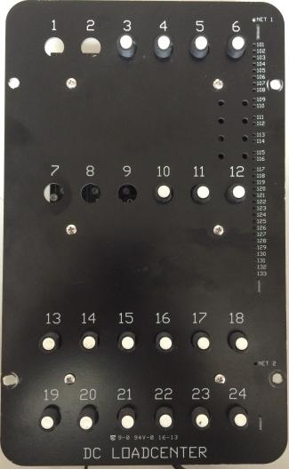
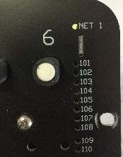
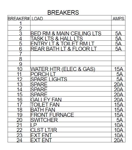
2 DRIVER ON 12V MTR OFF ON ENTRY STEP OFF ALLEGRO 'OPEN ROAD' NETWORK DIAGRAM DCBR24-33 PANEL CDC PANEL (no network connection) FRONT VIEW PARK PARK/ IGN IGN FUSED BATT 1 FUSED BATT 2 HOUSE DISC A B C D E F G H I J MID BATH CEILING WATER PUMP VENT FAN VENT LID BEDROOM PRIV. BATH GALLEY 1 GALLEY 2 ENTRY1 EXTEND DRIVER RETRACT CEILING WATER PUMP GAS HTR ELEC HTR DRIVER EXTEND DRIVER RETRACT MAIN CEILING LIGHT ENTRY LIGHT PASS. EXTEND PASS. RETRACT VENT FAN VENT LID WATER PUMP PANEL PASS. EXTEND PASS. RETRACT PORCH LIGHT DOOR LIGHT MAIN CEILING GALLEY O/H E E E E F F 12.5 F Volts F MAIN CEILING GALLEY O/H TASK MID HALL VENT FAN VENT LID TASK MID HALL (ON) LIGHT MASTER (OFF) PANEL
3 DCBR CONTROL SYSTEM LAYOUT FOR: TIFFIN MOTORHOMES SPYDER CONTROLS SYSTEM 2014 ALLEGRO PINOUT DIAGRAM PRODUCTION VERSION 05 / 05 / 2014 BREAKER # LOAD AMPS Bed RM LTS & Main Ceiling LTS 4 Task LTS & Hall LTS 5 Entry LT & Toilet RM LT 6 Rear Bath LT & Floor LT Water HTR (Elec& Gas) 1 11 Porch LT 12 Spare Lights 13 Toilet 3 14 Spare 15 Spare 16 Galley Fan 1 17 Toilet Fan 1 18 Bath Fan 1 19 Front Furnace 1 20 Switcher 21 LP 22 CLST LT/IR 23 A/C Power 24 Ext Ent CON J2 - OUTPUTS Pin 8: BED RET Pin 7: BED EXT Pin 6: P/S FR RET Pin 5: P/S FR EXT Pin 4: VANITY RET Pin 3: VANITY EXT Pin 2: D/S FR RET Pin 1: D/S FR EXT CON J12 - PUMP SW & WTR HTR Pin 4: WATER PMP STATUS Pin 3: WATER PMP SWITCH Pin 2: WATER HTR WARNING Pin 1: WATER PMP SWI GND J12 CON J1 - SWITCHED OUTPUTS Pin 1: BED RM LTS (BR #3) Pin 2: MAIN CEILING LTS (BR #3) Pin 3: TASK LTS (BR #4) Pin 4: HALL LTS (BR #4) Pin 5: ENTRY LT (BR #5) Pin 6: TOILET RM LT (BR #5) Pin 7: REAR BATH LT (BR #6) Pin 8: FLOOR LT (BR #6) CON J5 - POWER INPUTS Pin 1: HWH PUMP 12V+ IN (FROM CDC PANEL) Pin 2: FUSED 12V+ INPUT (FROM BATTERY) Pin 3: AWNING 12V+ IN (FROM CDC PANEL) Pin 4: UNUSED Pin 5: UNUSED CON J6 - SWITCHED OUTPUTS Pin 8: (BR #12) Pin 7: PORCH LT (BR #11) Pin 6: WATER HEATER - ELEC (BR #10) Pin 5: WATER HEATER - GAS (BR #10) Pin 4: HYDRAULIC PUMP Pin 3: WATER PUMP Pin 2: AWNING EXT Pin 1: AWNING RET CON J8 - FAN OUTPUTS Pin 6: GALLEY FAN DN (BR #18) Pin 5: GALLEY FAN UP (BR #18) Pin 4: GALLEY FAN ON/OFF (BR #18) Pin 3: TOILET FAN DN (BR #17) Pin 2: TOILET FAN UP (BR #17) Pin 1: TOILET FAN ON/OFF (BR #17) CON J7 - FAN OUTPUTS Pin 1: BATH FAN ON/OFF (BR #16) Pin 2: BATH FAN UP (BR #16) Pin 3: BATH FAN DN (BR #16) CON J9 - BREAKER OUTPUTS Pin 1: (TOILET (BR #13) Pin 2: () (BR #14) Pin 3: () (BR #15) Pin 4: UNUSED CON J100 - SENSOR INPUTS Pin 5: SENSOR COMMON GND Pin 4: 0-90 OHM LP GAS SNSR Pin 3: BLACK WTR SNSR Pin 2: GREY WTR SNSR Pin 1: FRESH WTR SNSR J100 GND INPUT 12V+ MAIN POWER INPUT CON J10 - BREAKER OUTPUTS Pin 1: FRONT FURNACE (BR #19) Pin 2: SWITCHER (BR #20) Pin 3: LP (BR #21) Pin 4: CLST LT/IR (BR #22) Pin 5: A/C POWER (BR #23) Pin 6: (BR #24)
4 FLOOR LTS ( PIN 1-8, LED 108) REAR BATH LTS ( PIN 1-7, LED 107) TOILET ROOM LTS ( PIN 1-6, LED 106) ENTRY LT ( PIN 1-5, LED 105) HALL LTS ( PIN 1-4, LED 104) TASK LTS ( PIN 1-3, LED 103) MAIN CEILING LTS ( PIN 1-2, LED 102) BED RM LTS ( PIN 1-1, LED 101) BREAKER# LOAD BREAKERS BED RM & MAIN CEILING LTS TASK LTS & HALL LTS ENTRY LT & TOILET RM LT REAR BATH LT & FLOOR LT WATER HTR (ELEC & GAS) PORCH LT GALLEY FAN TOILET FAN BATH FAN FRONT FURNACE SWITCHER LP CLST LT/IR AMPS J12 J100 GND INPUT 12V MAIN POWER INPUT DESC. DCBR PANEL DESIGN FOR: TIFFIN ALLEGRO REV # 1v0 SPYDER CONTROLS CORP JAN 21/2015 TYPE: ELECTRICAL DRAWING
5 BREAKER# LOAD BREAKERS BED RM & MAIN CEILING LTS TASK LTS & HALL LTS ENTRY LT & TOILET RM LT REAR BATH LT & FLOOR LT WATER HTR (ELEC & GAS) PORCH LT GALLEY FAN TOILET FAN BATH FAN FRONT FURNACE SWITCHER LP CLST LT/IR AMPS J12 M AWNING RET (PIN 6-2, LED 118) AWNING EXT (PIN 6-1, LED 117) AWNING 12V+ INPUT FROM CDC PANEL (PIN 5-3) BATH FAN LID DN (PIN 7-3, LED 127) BATH FAN LID UP (PIN 7-2, LED 126) M LID CDC PANEL (15 AMP BREAKER/ PIN # D5) M FAN M LID GALLEY FAN DN (PIN 8-6, LED 133) GALLEY FAN UP (PIN 8-5, LED 132) GALLEY FAN ON/OFF (PIN 8-4, LED 131) BATH FAN ON/OFF (PIN 7-1, LED 125) TOILET FAN ON/OFF (PIN 8-1, LED 128) TOILET FAN LID UP (PIN 8-2, LED 129) TOILET FAN LID DN (PIN 8-3, LED 130) M FAN M LID M FAN NOTE: Park Brake must be ON in order for this wire/output to supply 12V+ to the DCBR24-33 House Panel J100 GND INPUT 12V+ MAIN POWER INPUT DESC. DCBR PANEL MOTORS DESIGN FOR: TIFFIN ALLEGRO REV # 1v0 SPYDER CONTROLS CORP JAN 21/2015 TYPE: ELECTRICAL DRAWING
6 BREAKER# LOAD BREAKERS BED RM & MAIN CEILING LTS TASK LTS & HALL LTS ENTRY LT & TOILET RM LT REAR BATH LT & FLOOR LT WATER HTR (ELEC & GAS) PORCH LT GALLEY FAN TOILET FAN BATH FAN FRONT FURNACE SWITCHER LP CLST LT/IR AMPS BED RET (PIN 2-8, LED 116) SWINTECH BED RET (PIN 2-7, LED 115) P/S FR EXT (PIN 2-6, LED 114) P/S FR EXT (PIN 2-5, LED 113) D/S FR RET (PIN 2-2, LED 110) D/S FR EXT (PIN 2-1, LED 109) HWH CONTROLLER VANITY RET (PIN 2-4, LED 112) J12 SWINTECH VANITY EXT (PIN 2-3, LED 111) HYDRAULIC PUMP (PIN 3-4, LED 120) HWH PUMP 12V+ INPUT (PIN 5-1) CDC PANEL 30A BREAKER/ PIN #E5 NOTE: IGN & Park Brake must be ON in order for this wire/output to supply 12V+ to the DCBR24-33 House Panel J100 GND INPUT 12V MAIN POWER INPUT DESC. DCBR PANEL CTRL DESIGN FOR: TIFFIN ALLEGRO REV # 1v0 SPYDER CONTROLS CORP JAN 21/2015 TYPE: ELECTRICAL DRAWING
7 BREAKER# LOAD BREAKERS BED RM & MAIN CEILING LTS TASK LTS & HALL LTS ENTRY LT & TOILET RM LT REAR BATH LT & FLOOR LT WATER HTR (ELEC & GAS) PORCH LT GALLEY FAN TOILET FAN BATH FAN FRONT FURNACE SWITCHER LP CLST LT/IR AMPS J12 GND INPUT 12V+ MAIN POWER INPUT J100 BLACK TANK (PIN 11-3) COMMON GND FROM CDC PANEL (PIN 11-5) FRESH TANK (PIN 11-1) LPG (PIN 11-4) 1/2 1/4 3/4 E F BLACK GREY FRESH GREY TANK (PIN 11-2) ALLEGRO TANK MONITOR SYSTEM DESC. DCBR PANEL DESIGN FOR: TIFFIN ALLEGRO REV # 1v0 SPYDER CONTROLS CORP JAN 21/2015 TYPE: ELECTRICAL DRAWING
8 BREAKER# LOAD BREAKERS BED RM & MAIN CEILING LTS TASK LTS & HALL LTS ENTRY LT & TOILET RM LT REAR BATH LT & FLOOR LT WATER HTR (ELEC & GAS) PORCH LT GALLEY FAN TOILET FAN BATH FAN FRONT FURNACE SWITCHER LP CLST LT/IR AMPS WATER PUMP SWITCH WATER PUMP STATUS (PIN 12-4) J12 WATER PUMP SWITCH (PIN 12-3) WATER PUMP SWITCH GND (PIN 12-1) NOTE: This fuse must be good in order for the relay in the DCBR24-33 panel to power the water pump. WATER HEATER WATER HEATER - ELEC (PIN 6-6, LED 122) WATER HEATER - GAS (PIN 6-5, LED 121) FUSED 12V+ INPUT FROM HOUSE BATT WATER PUMP (PIN 6-3, LED 121) M BATT J100 GND INPUT 12V+ MAIN POWER INPUT DESC. DCBR PANEL WATER/HTR DESIGN FOR: TIFFIN ALLEGRO REV # 1v0 SPYDER CONTROLS CORP JAN 21/2015 TYPE: ELECTRICAL DRAWING
9
10 A/C CONDENSOR FAN 12V MASTER DISC. LATCHING SOLENOID (190A max) FUSED BATTERY INPUT (5/16" STUD INSIDE PANEL) TOP VIEW OUTPUT TO REAR HOUSE BREAKERS (5/16" STUD INSIDE PANEL) FRONT VIEW ø 1.000" LEFT SIDE VIEW PARK PARK/ IGN IGN FUSED BATT 1 FUSED BATT 2 HOUSE DISC. 1 RIGHT SIDE VIEW A B C D E F G H I J A/C FAN SWITCH ON DASH 12V+ 3-PIN INLINE TYCO MATE-N-LOK PIN #1 - SHOWN IN LOADED VIEW 12V MASTER SW SPDT MOMENTARY 5 amp RATING 12V MASTER SWITCH SUPPLY (12V OUTPUT 3 amps) 12V MASTER CONNECT INPUT 12V MASTER DISCONNECT INPUT 12V+ TO A/C CONDENSOR FAN 4-PIN INLINE TYCO MATE-N-LOK PIN #1 - SHOWN IN LOADED VIEW IGNITION INPUT (12V) PARK BRAKE INPUT (GROUND) EMERGENCY START SWITCH INPUT IGN. SWITCH PARK SWITCH EMERG. SWITCH 5 amp RATING EMERGENCY START SWITCH SUPPLY BACK VIEW (12V OUTPUT 3 amps) J I H G F E D C B A 6-PIN INLINE TYCO MATE-N-LOK PIN #1 - SHOWN IN LOADED VIEW 'I' 12V HOUSE DISC. 'H' FUSED BATT. #2 FRIDGE(CONNECT DRIVER SEAT TO 'STAB') CARGO PASS. SEAT 'G' FUSED BATT. #1 FANS, MAP LTS,RADIO SATELITE 'F' IGNITION MIRRORS CAMERA 'E' PARK / IGN DINETTE GALLEY 'D' PARK BRAKE AWNING (TO DCBR24-33) INVERTER HOOD SHADES FRIDGE LOCK (OPTION) BED PART DESCRIPTION: 12V USB OUTLET A/C FAN (CENTER ) WIPER TRAILER 12V PWR ENT. STEP SW (WHT) ENT. STEP (RED) WINDOW JACKS ENTRY STEP (YEL) VANITY HWH SYSTEM (TO DCBR24-33) ALLEGRO DC PANEL DATE 2015/03/19 REV #: SPYDER CONTROLS 1.1
11 12v+ IGN BATTERY MERGE SOLENOID CDC PANEL EMERG. START SW. PARK BRAKE SW. IGN SW. PIN 1 PIN 1 0.2A BATTERY DISCONNECT SWITCH (SPDT MOMENTARY) 3A 14 GA GROUND INPUT WIRE (BLACK) GREEN GREEN 70A 70A AWNING PARK / IGN IGN FUSED BATTERY 12V+ INPUT PIN 1 PIN 1 PIN 1 HOUSE DISCONNECT DIAGRAM DESCRIPTION: TIFFIN CDC PANEL PART NUMBER: DATE: REV #: 1v3 C
12
Trouble Shooting Leveling Control Box Electric Jacks. Touch Pad LED Probable Cause Solution
 Trouble Shooting Leveling Control Box 140-1224 Electric Jacks Copyright Power Gear Issued: January 2013 #82-L0524, Rev. OA Touch Pad LED Probable Cause Solution 1. On/Off LED will not light 2. Wait LED
JRVCS2 RV CONTROL AND MONITORING SYSTEM
 JRVCS2 RV CONTROL AND MONITORING SYSTEM Installation and Operation Manual Patent # (D776,068) Patent # (D762,644) Patent # (9,679,635) Important Safety Information Read the in-command Manual, and these
NCSP3. Installation and Operation Manual RV CONTROL AND MONITORING SYSTEM. Patent # (D776,068) Patent # (D762,644) Patent # US 9,679,735
 Patent # (D762,644) Patent # US 9,679,735") RV CONTROL AND MONITORING SYSTEM Installation and Operation Manual Patent # (D776,068) Patent # (D762,644) Patent # US 9,679,735 Important Safety Information Read the in-command Manual, and these warnings
RV CONTROL AND MONITORING SYSTEM Installation and Operation Manual Patent # (D776,068) Patent # (D762,644) Patent # US 9,679,735 Important Safety Information Read the in-command Manual, and these warnings
VCM Systems Vehicle Control Module Systems
 VCM Systems Vehicle Control Module Systems Technical Manual VCMS-SC (Standard Configuration) Switch Panel System The Model VCMS-SC Switch Panel System is a standard configuration of the VCMS product family
 http://www.prodemand.com/print/index?content=tabs&module=true&tab=true&terms=t... Page of 0/0/0 Service Manual: WIRING DIAGRAMS - R00 PERFORMANCE >.L 00 Dodge Pickup.L Eng R00 Fig :.L, Engine Performance
Vehicle DC-DC 120W User Guide DCX 3
 Vehicle DC-DC 0W User Guide DCX Technical support: Email: tsupport@opussolutions.com Tel:- 949-87-00 x5 Package Contents DCX.0 Automotive ATX/ITX & AT intelligent DC-DC0W Power Supply - 4 pin ATX power
SilverLeaf RV-C Control System Training Manual
 2013 SilverLeaf RV-C Control System Training Manual Newmar Corporation Revised Jan. 2013 Newmar SilverLeaf RV-C Control System Operation/Set-UP Manual SCREEN ACCESS Please be aware that not all of the
V-MUX CONNECTOR and ACCESSORY SPEC
 P V-MUX V-MUXP CONNECTOR AND ACCESSORY REFERENCE SPECIFICATION August 2007 8/2/07 Page 1 of 26 V-MUX nodes for all multiplex applications: Hercules #6000-0000-03 (16) wired switch Inputs (3) wired 0-5V
P M C L O G I C. 10 Inputs High-side or Low-side /110 PMC 10 Channel Input Module. PMC Input Module 110
 10 Inputs High-side or Low-side 00-00622-100/110 PMC 10 Channel Input Module PMC Input Modules 100 and 110 are members of Intellitec's Programmable Multiplex Control family. They work in combination with
Illustrated Parts List - AXA 2400 Compact kva
 1. Illustrated parts list Please refer to www.itwgse.com/axapower for recommended list of spare parts. It is also possible to find diagrams and drawings of the unit at this website. Comp. No.: Name (Part
JRVCS105. RV CONTROL AND MONITORING SYSTEM Installation and Operation Manual. Patent # 9,679,644
 JRVCS105 RV CONTROL AND MONITORING SYSTEM Installation and Operation Manual Patent # 9,679,644 Important Safety Information Read the in-command Manual, and these warnings and instructions carefully before
SMM501/501-H (Surveillance Mode Module) Ford Police Interceptors (Sedan and SUV)
 Ford Police Interceptors (Sedan and SUV)") An ISO 9001:2008 Registered Company SMM501/501-H (Surveillance Mode Module) 2013-2014 Ford Police Interceptors (Sedan and SUV) Introduction The SMM501/501-H is intended for 2013 and 2014 Ford Police Interceptors
An ISO 9001:2008 Registered Company SMM501/501-H (Surveillance Mode Module) 2013-2014 Ford Police Interceptors (Sedan and SUV) Introduction The SMM501/501-H is intended for 2013 and 2014 Ford Police Interceptors
DirectCommand Installation RoGator 864/874/1064/1074 (MY 2006 & Earlier) Ag Leader Technology
 Ag Leader Technology") Note: Indented items indicate parts included in an assembly listed above Part Name/Description Part Number Quantity Direct Command Kit 4100524 1 Generic Cable Installation Kit 2000901-1 1 Hardware Kit
Note: Indented items indicate parts included in an assembly listed above Part Name/Description Part Number Quantity Direct Command Kit 4100524 1 Generic Cable Installation Kit 2000901-1 1 Hardware Kit
R. C. Tronics Incorporated
 R. C. Tronics Incorporated Specializing In Electronic Controls 16573 County Road 38 Goshen, Indiana 46528 Toll Free 1-800-642-8171 Phone 1-574-642-3857 Fax 1-574-642-3858 http://www.rctronics.com Electronic
JRVCS105 RV CONTROL AND MONITORING SYSTEM
 RV CONTROL AND MONITORING SYSTEM Installation and Operation Manual TABLE OF CONTENTS Table of Contents... 2 Introduction... 4 Thank You!... 4 Features... 4 Precautions... 4 Packing List... 錯誤! 尚未定義書籤 Installation...
Call Toll Free: Website:
 1 2 Introducing Road Commander Intellitec is launching a new product family, named Road Commander that will allow you to control your RV systems via a touch screen, control center, or smart phone, whether
Professional Digital Two-Way Radio System MOTOTRBO Mobile. Radio Installation Manual
 Professional Digital Two-Way Radio System MOTOTRBO Mobile Radio Installation Manual DM 3400 Numeric Display Mobile DM 3401 Numeric Display Mobile (with GPS) DM 3600 Display Mobile DM 3601 Display Mobile
CS5100DV Tech Sheet. Cal Spas. System PN System Model # VSP-CS5100DV-BCAH Software Version # 46 EPN # 3288
 CS5100DV Tech Sheet Cal Spas System PN 55736-01 System Model # VSP-CS5100DV-BCAH Software Version # 46 EPN # 3288 Base PCBA - PN 55737-01 PCB VS500DVH - PN 23928 Rev A Base Panels VL260 PN 54754-03 with
USB INTERFACE SYSTEM DIG-703A / DIG-703B PRODUCT MANUAL. DOC-114 Rev 1.7. Copyright 2013 All Rights Reserved
 instrumentation and software for research USB INTERFACE SYSTEM DIG-703A / DIG-703B PRODUCT MANUAL DOC-114 Rev 1.7 Copyright 2013 All Rights Reserved Med Associates, Inc. P.O. Box 319 St. Albans, Vermont
Wiring Diagrams DIAGRAM INDEX. POWER SCHEMATICS Unit 30GXN,R Voltage Figure Number
 30GXN,R Sizes 080-528 Air-Cooled Chillers with ComfortLink Controls 50/60 Hz Wiring Diagrams DIAGRAM INDEX POWER SCHEMATICS Unit 30GXN,R Voltage Figure Number Label Diagram No. 30GX 080-178* ALL 1 505429
Appendix E: Edge Ti. Overview. Appendix E: Edge Ti 169
 Appendix E: Edge Ti 169 Appendix E: Edge Ti Overview The Edge Ti shape cutting control is an extremely versatile product offering up to four configurable axes of motion, built-in Servo Amplifiers and configurable
Operating Instructions. For. Level Control Module. Model SSR 1000
 Operating Instructions For Level Control Module Model SSR 1000 SSR Operation Instructions Rev. 1 Jan 01 Page 1/7 1. Note Please read and take note of these operating instructions before unpacking and commissioning.
NCSP35. Installation and Operation Manual RV CONTROL AND MONITORING SYSTEM. Patent # US 9,679,735
 RV CONTROL AND MONITORING SYSTEM Installation and Operation Manual Patent # US 9,679,735 Important Safety Information Read the in-command Manual, and these warnings and instructions carefully before using
Isolation Verification Control Mining - Marine - Transit Solutions LIVE Distributed By Locksafe Industrial Safety Equipment
 Isolation Verification Control Mining - Marine - Transit Solutions LIVE Isolation Verification Control- Operational Features Part No- LSLIVC www.lingona.com.au The LSLIVC Isolation Verification control
DirectCommand Installation 5 Channel Spreader Control Module Technology
 DirectCommand Installation Ag Leader Technology Note: Indented items indicate parts included in an assembly listed above Part Name/Description Part Number Quantity Direct Command Kit 4100582 1 Cable Installation
DirectCommand Installation RoGator Model Year Ag Leader Technology
 Note: Indented items indicate parts included in an assembly listed above Part Name/Description Part Number Quantity Direct Command Kit 4100801 1 Dual Lock 2000052-9 1 Dual Lock 2000053-9 1 Quick Reference
MEGA DIAL PANEL Instructions
 2036 Fillmore Street Davenport, Ia. 52804 563-324-1046 www.racedigitaldelay.com MEGA DIAL PANEL Instructions WARRANTY AND DISCLAIMER DIGITAL DELAY ELECTRONICS INC. WARRANTS THE PRODUCTS IT MANUFACTURES
VIM Mercedes Benz Sprinter Contact Intermotive for additional applications
 An ISO 9001:2008 Registered Company VIM910 2017 Mercedes Benz Sprinter Contact Intermotive for additional applications Introduction The VIM will allow the OEM steering wheel switches to control aftermarket
CS6300DV Tech Sheet. Cal Spas. System PN System Model # VSP-CS6300DV-BCAH Software Version # 45 EPN # 3092
 CS6300DV Tech Sheet Cal Spas System PN 55740 System Model # VSP-CS6300DV-BCAH Software Version # 45 EPN # 3092 Base PCBA - PN 5574 PCB VS500DVH - PN 23928 Rev A Base Panels Mini-dash PN 53850-06 with Overlay
NCSP3. Installation and Operation Manual RV CONTROL AND MONITORING SYSTEM. Patent # (D776,068) Patent # (D762,644) Patent # US 9,679,735
 Patent # (D762,644) Patent # US 9,679,735") RV CONTROL AND MONITORING SYSTEM Installation and Operation Manual Patent # (D776,068) Patent # (D762,644) Patent # US 9,679,735 Important Safety Information Read the in-command Manual, and these warnings
RV CONTROL AND MONITORING SYSTEM Installation and Operation Manual Patent # (D776,068) Patent # (D762,644) Patent # US 9,679,735 Important Safety Information Read the in-command Manual, and these warnings
Balboa Water Group. System PN System Model # MM7-VS100-HCAK Software Version # 41 EPN # Base PCBA - PN PCB VS100 - PN Rev B
 VS100 Tech Sheet Balboa Water Group System PN 54655 System Model # MM7-VS100-HCAK Software Version # 41 EPN # 3450 Base PCBA - PN 54656 PCB VS100 - PN 22964 Rev B Base Panels VL200 (Mini) PN 55123 VL240
CS6200DV Tech Sheet. Cal Spas. System PN System Model # VS5-CS6200DV-BCAH Software Version # 45 EPN # 3091
 CS6200DV Tech Sheet Cal Spas System PN 55738 System Model # VS5-CS6200DV-BCAH Software Version # 45 EPN # 309 Base PCBA - PN 55739 PCB VS500DVH - PN 23928 Rev A Base Panels Mini-dash PN 53850-06 with Overlay
Thetford Corp. Refrigerator Replacement Parts List
 Thetford Corp. Refrigerator Replacement Parts List NE SERIES NE SERIES NE SERIES NE.F NE.F NE.F Part No. 677 NORCOLD /8/08 Cabinet Area - Front View - NE 7 6 6 0 9 8 ART 0 NO. PART # DESCRIPTION NE.F 670
STATUS Shiloh Road Alpharetta, Georgia (770) FAX (770) Toll Free
 FAX (770) Toll Free") Instruction Manual Model 1582-45L Data Switch September 2010, Rev A REMOTE LOCAL SWITCH STATUS SELECT REMOTE LOCAL LOCAL SELECT CHANNEL SELECT POWER MODEL 1582 SWITCH CROSS TECHNOLOGIES, INC. Data, drawings,
Instruction Manual Model 1582-45L Data Switch September 2010, Rev A REMOTE LOCAL SWITCH STATUS SELECT REMOTE LOCAL LOCAL SELECT CHANNEL SELECT POWER MODEL 1582 SWITCH CROSS TECHNOLOGIES, INC. Data, drawings,
VS501Z Hot Sheet. Balboa Instruments. System PN System Model # VSP-VS501Z-CCAH Software Version # 43 EPN # 2720
 VS50Z Hot Sheet Balboa Instruments System PN 54356-03 System Model # VSP-VS50Z-CCAH Software Version # 43 EPN # 2720 Base PCBA - PN 54357-03 PCB VS500Z - PN 22972 Rev C or D Base Panels VL40 (LCD Lite
INTELLIGENT DOCKING STATION USERS MANUAL
 Kodiak Mobile by Jotto Desk 209 W. Easy St., Rogers, AR USA 72756 Customer Service: 877.455.6886 http://www.kodiakmobile.com PART NUMBER: 450-4011 - Last Update: 06.2009 INTELLIGENT DOCKING STATION USERS
GAME OF THRONES SERVICE AND OPERATION MANUAL
 GAME OF THRONES SERVICE AND OPERATION MANUAL WARNING MANUAL #780-50G4-00 GAME OF THRONES PRO #500-55G4-01 1-800-KICKERS - parts.service@sternpinball.com www.sternpinball.com - facebook.com/sternpinball
VS515Z Tech Sheet. Balboa Instruments. System PN System Model # VSP-VS515Z-YCAH Software Version # 43 EPN # 2816
 VS515Z Tech Sheet Balboa Instruments System PN 55476 System Model # VSP-VS515Z-YCAH Software Version # 43 EPN # 2816 Base PCBA - PN 55477 PCB VS500Z - PN 22972 Rev D Base Panels VL400 PN 55129 Template
RAM Rail Mount Kit RAM 201U 5 Arm RAM 2461U Monitor Mount RAM 235U Base, Double U-Bolt
 Note: Indented items indicate parts included in an assembly listed above Part Name/Description Part Number Quantity DirectCommand Kit 4100800 1 Cable Installation Kit 2000901-1 1 Dielectric Grease 2002872
Blue Point Engineering
 Blue Point Engineering SV203 Interface Overview Overview Sensors Light Sensor Motion Sensor Joystick Computer USB PORT Technical Pointing the Way to Solutions! T http://www.bpesolutions.com Animatronic
POWER Shiloh Road Alpharetta, Georgia (770) FAX (770) Toll Free
 FAX (770) Toll Free") Instruction Manual Model 1582-10M Protection Switch January 2009 Rev O ALARMS MENU OUTPUT = CH1 AUTO POWER 1 2 MODEL 1582 SWITCH CROSS TECHNOLOGIES INC. CH1 CH2 REMOTE EXECUTE Data, drawings, and other
Instruction Manual Model 1582-10M Protection Switch January 2009 Rev O ALARMS MENU OUTPUT = CH1 AUTO POWER 1 2 MODEL 1582 SWITCH CROSS TECHNOLOGIES INC. CH1 CH2 REMOTE EXECUTE Data, drawings, and other
*740130* 2800, 9500 Series. Cable Companion Motor Power. Cable AC Power. Cable Retrofit Acessories
 *00* 00 Senior Swing Control Box 00, 900 Series Retrofit Instructions Retrofit Cables = = WHT = = NO WIRE -00 0V POWER CONNECTION Cable AC Power = = YEL = WHT/ = RED = = WHT/RED Cable Motor Power = =YEL
Holding Tank Monitors for RVs BUYER S GUIDE
 SEELEVEL II TM Holding Tank Monitors for RVs BUYER S GUIDE Printed in Canada MADE IN CANADA SEELEVEL II TANK MONITOR LEVEL IN PERCENT BATT FRESH GREY BLACK LPG MADE IN CANADA MADE IN CANADA SS SeeLeveL
Rexroth Controller Installation & Operations Manual
 Electric Drives and Controls Hydraulics Linear Motion and Assembly Technologies Pneumatics Service Rexroth - 105 Controller Installation & Operations Manual The Drive & Control Company Table of Contents:
Abstract. GLV User Manual 1
 GLV User Manual 1 Abstract This user manual is a high level document that explains all operational procedures and techniques needed to operate the GLV system in a safe and effective manner. Anyone operating
User Guide Chevrolet Volt
 User Guide Chevrolet Volt Accessory Power Control Module General Motors Part Numbers 24262765 and 24261518 Copyright 2015 EVTV LLC 0 INTRODUCTION The Accessory Power Control Module, sometimes referred
ADDENDUM FOR 20, 27, & 28 OPTIONS
 ADDENDUM FOR 20, OPTIONS GENERAL The 20, 27, and 28 option provides for an alarm contact OR an AC transfer switch on EXELTECH XP Series inverters. The alarm relay monitors the inverter s AC output and
Contents. Cabinet Components " Exploded View... 1 " Usage List U.S. Models... 2 " Usage List Canadian Models... 3 " Blank Page...
 Replacement Parts Manual WAG SERIES COMBINATION GAS / ELECTRICS Models: WAG30D WAG36D WAG40D General Notes! Revised and/or additional pages may be issued from time to time.! A complete and current manual
Ag Leader Technology. DirectCommand Installation RoGator Model Years
 Note: Indented items indicate parts included in an assembly listed above Part Name/Description Part Number Quantity Direct Command Kit 4100550 1 Dual Lock 2000052-9 1 Dual Lock 2000053-9 1 Hardware Kit
DC3IOB Revision User Guide Updated 7/12/12. Overview
 DC3IOB Revision 080910 User Guide Updated 7/12/12 Overview The DC3IOB is a three axis DC brush motor drive with an integrated PLC. A range of motor drive currents are selectable with jumper blocks. The
VS510SZ Tech Sheet. Balboa Instruments. System PN System Model # VSP-VS510SZ-DCAH Software Version # 43 EPN # 2765
 VS0SZ Tech Sheet Balboa Instruments System PN 437-02 System Model # VSP-VS0SZ-DCAH Software Version # 43 EPN # 27 Base PCBA - PN 4372-02 PCB VS00Z - PN 22972 Rev C or D Base Panels VL700S PN 38 VL70S (Serial
AX1500. Dual Channel Digital Motor Controller. Quick Start Manual. v1.9b, June 1, 2007
 AX1500 Dual Channel Digital Motor Controller Quick Start Manual v1.9b, June 1, 2007 visit www.roboteq.com to download the latest revision of this manual Copyright 2003-2007 Roboteq, Inc. SECTION 1 Important
CONTROL PROTOCOL Motorized Projection Screens
 CONTROL PROTOCOL Motorized Projection Screens Table of Contents Overview... 3 Control Wiring Diagram... 3 IR Control... 4 Remote Button IR Hex Commands... 4 12 Volt DC Trigger... 5 Contact Closure and
AUDI-09 EXT MMi NTV-KIT187
 3950 NW 120 th Ave, Coral Springs, FL 33065 TEL 561-955-9770 FAX 561-955-9760 www.nav-tv.com info@nav-tv.com AUDI-09 EXT MMi NTV-KIT187 Overview The AUDI-09 EXT MMi Kit allows the user to add up to 3 video
Model HM-535 Power Supply Installation and Service Instructions
 Model HM-535 Power Supply Installation and Service Instructions 430-535 0104 2004 Heritage MedCall, Inc SENTRY INSTALLATION & SERVICE INSTRUCTIONS POWER SUPPLY UNIT Model HM-535 IMPORTANT SAFETY INSTRUCTIONS
MicroGuard 586 Retrofit
 MicroGuard 586 Retrofit Rated Capacity Indicator System Troubleshooting Contents Troubleshooting... 1 System Fault Messages... 1 Extension Reel Voltage Checks... 3 Computer Internal Status Indicators...
INSTALLATION INSTRUCTIONS
 LIGHTING CONTROL PANELS 16 AND 24 RELAYS INSTALLATION INSTRUCTIONS INSTALLATION OVERVIEW The installation instructions contained in this document are provided as a guide for proper and reliable installation.
UNIPORT V2. Uniport V2
 UNIPORT V2 Uniport V2 USB powered Parallel port interconnection board with optical isolated inputs, buffered outputs, charge pump interlock and power relays Specification Full optical isolation of all
Ag Leader Technology. DirectCommand Installation Hardi 20-pin Interface Kit (Sprayer Chassis Mount)
") Part Name / Description Part Number Quantity DirectCommand Hardi Sprayer Kit 4100882 1 Dust Receptacle 8-pin 2002975-8C 1 Installation Instructions 2006335 1 Quick Reference Card- Liquid Application 2002831-38
Part Name / Description Part Number Quantity DirectCommand Hardi Sprayer Kit 4100882 1 Dust Receptacle 8-pin 2002975-8C 1 Installation Instructions 2006335 1 Quick Reference Card- Liquid Application 2002831-38
RAM Rail Mount Kit RAM 201U 5 Arm RAM 2461U Monitor Mount RAM 235U Base, Double U-Bolt
 DirectCommand Installation Ag Leader Technology Note: Indented items indicate parts included in an assembly listed above Part Name/Description Part Number Quantity DirectCommand Kit 4100852 1 Cable Installation
Note: These installation instructions are only for the 4430/4440 Sprayer. For other SPX models please refer to P/N , &
 DirectCommand Installation Ag Leader Technology Note: These installation instructions are only for the 4430/4440 Sprayer. For other SPX models please refer to P/N 2005944, 2005945 & 2006383. Part Name/Description
WALL MOUNTED PACKAGE AIR CONDITIONER REPLACEMENT PARTS MANUAL. Models: WA181, WA241. Contents. General Notes. Important
 REPLACEMENT PARTS MANUAL WALL MOUNTED PACKAGE AIR CONDITIONER Models: WA181, WA241 General Notes Ø Ø Revised and/or additional pages may be issued from time to time. A complete and current manual consists
MODEL KP-100 ACCESS CONTROL DIGITAL KEYPAD OPERATING INSTRUCTIONS
 MODEL KP-100 ACCESS CONTROL DIGITAL KEYPAD OPERATING INSTRUCTIONS Model KP-100 is a self-contained digital keypad. This keypad is suitable for residential, industrial, and commercial installations. It
Illustrated Parts List
 AXA 2400 Illustrated Parts List GPU 30-90kVA CE & UL Table of Content AXA 2400 GPU...1 Front and Back View - Outside...1 Front Door Inside...2 Front view - Inside with Cover...3 Front view Inside behind
Nature Power Inverters. Modified Sinewave 1000w/1500w True Sinewave 1000w/2000w. Owner s Manual
 Nature Power Inverters Modified Sinewave 1000w/1500w True Sinewave 1000w/2000w Owner s Manual Modified Sinewave Series True Sinewave Series For safe and optimum performance, the Power Inverter must be
ISO 9001 CERTIFIED. 607 NW 27th Ave Ocala, FL Phone: (352) or Fax: (352) SUITABLE FOR EXTERNAL DISTRIBUTION
 or Fax: (352) SUITABLE FOR EXTERNAL DISTRIBUTION") ISO 9001 CERTIFIED Phone: (352) 629-5020 or 800-533-3569 Fax: (352)-629-2902 ES-Key 12- Relay Board P/N 103190 and 103338 PAGE 1 of 13 1. REVISI LOG... 2 2. OVERVIEW... 3 2.1. PART NUMBERS... 3 2.2. MODULE
ISO 9001 CERTIFIED Phone: (352) 629-5020 or 800-533-3569 Fax: (352)-629-2902 ES-Key 12- Relay Board P/N 103190 and 103338 PAGE 1 of 13 1. REVISI LOG... 2 2. OVERVIEW... 3 2.1. PART NUMBERS... 3 2.2. MODULE
MASTER SERIES XE36 XPRESS GRILL (Electric) NON-CE & CE VERSION
 NON-CE & CE VERSION") MASTER SERIES XE36 XPRESS GRILL (Electric) NON-CE & CE VERSION PA R TS LI IS T Toll Free Phone, (US & Canada): (800) 427-6668 Toll Free Fax, (US & Canada): (800) 361-7745 http://www.garland-group.com FORM
MASTER SERIES XE36 XPRESS GRILL (Electric) NON-CE & CE VERSION PA R TS LI IS T Toll Free Phone, (US & Canada): (800) 427-6668 Toll Free Fax, (US & Canada): (800) 361-7745 http://www.garland-group.com FORM
FX-2 Control Board ASY-360-XXX Setup and Configuration Guide
 FX-2 Control Board ASY-360-XXX Setup and Configuration Guide Micro Air Corporation Phone (609) 259-2636 124 Route 526. WWW.Microair.net Allentown NJ 08501 Fax (609) 259-6601 Table of Contents Introduction...
FX-2 Control Board ASY-360-XXX Setup and Configuration Guide
 FX-2 Control Board ASY-360-XXX Setup and Configuration Guide Micro Air Corporation Phone (609) 259-2636 124 Route 526. WWW.Microair.net Allentown NJ 08501 Fax (609) 259-6601 Table of Contents Introduction...
DC3IOB Revision User Guide Updated 3/29/10. Overview
 Revision 080910 User Guide Updated 3/29/10 Overview The is a three axis DC brush motor drive with an integrated PLC. A range of motor drive currents are selectable with jumper blocks. The integrated PLC
Parts Diagrams and Lists
 SC351 Parts Diagrams and Lists www.crescentindustrial.co.uk TABLE OF CONTENTS GENERAL VIEW 1 COVER AND TANKS 3 FRAME SYSTEM 5 HANDLE SUPPORT SYSTEM 7 HANDLE SYSTEM 9 MOTOR AND DECK SYSTEM 13 BRUSH DECK
DirectCommand Installation DirectCommand Complete Wiring Harness
 Note: Indented items indicate parts included in an assembly listed above Part Name/Description Part Number With Switch Box Quantity by Model With Boom Switch Cable Display Cable Kit 4100814 1 1 Power Control
PRODUCT DATASHEET DATE. This report provides appropriate specifications for the FRDS GENII relay enclosure.
 ATTACHMENT 20 PAGE 1 Of 11 S: None 1 11 ELIGIBLE SERIAL S: PURPOSE: S/N. This report provides appropriate specifications for the FRDS GENII relay enclosure. SUMMARY: The data listed here is compiled from
BMS: Installation Manual v2.x - Documentation
 Page 1 of 7 BMS: Installation Manual v2.x From Documentation This section describes how external peripheral devices are connected and additional functions of the BMS are used. I you have not done so already,
PS-4100 POWER SUPPLY MANUAL
 PS-4100 POWER SUPPLY MANUAL Manual Part Number 180-0573 December 7, 2006 TABLE OF CONTENTS TITLE PAGE Table of Contents... 2 List Of Figures... 3 1. Introduction... 4 1.0. General... 4 1.1. Features...
Vehicle DC-DC 150W User Guide DCA 7
 Technical support: Email: tsupport@opussolutions.com Tel:1-949-387-1010 x225 Package Contents 1 DCA7.150. Automotive dual output intelligent DC-DC180W Power Supply 1-8 pin DC power output pigtail cable
PURE SINE WAVE INVERTER REMOTE GP-ISW-R-12/24
 PURE SINE WAVE INVERTER REMOTE GP-ISW-R-2/24 User Manual GP-ISW-R 5 4 3 2 0 gpelectric.com GP-ISW-R 20 Go Power! By Carmanah Technologies Worldwide Technical Support and Product Information gpelectric.com
Wiring Diagrams. Section. In this chapter...
 Wiring Diagrams In this chapter... Main Wiring Diagram Right-Side Wiring Diagram Left-Side Wiring Diagram Inside Front Wiring Diagram Inside Top Wiring Diagram Inside Top - printhead Wiring Diagram Section
Girard Awnings R ACMC Motor Controller (Last revised on May 10, 2008) A Visionary Awning Control by
 A Visionary Awning Control by") Girard Awnings R ACMC Motor Controller (Last revised on May 10, 2008) R A Visionary Awning Control by Girard AC Motor Controller Installation Guide ACMC Revision 2.08 May 10, July 2008 ACMC Installation
Girard Awnings R ACMC Motor Controller (Last revised on May 10, 2008) R A Visionary Awning Control by Girard AC Motor Controller Installation Guide ACMC Revision 2.08 May 10, July 2008 ACMC Installation
VDC x150A Dual Channel Forward/Reverse Brushed DC Motor Controller
 VDC2450 2x150A Dual Channel Forward/Reverse Brushed DC Motor Controller Roboteq s VDC2450 controller is designed to convert commands received from a RC radio, Analog Joystick, wireless modem, or microcomputer
Advanced Distribution Cable Junction Box For Spectra RMS Molded-Case Circuit Breakers with Advanced Feature microentelliguard TM Trip Units
 GE Energy Industrial Solutions GEH-704 Installation Instructions Advanced Distribution Cable Junction Box For Spectra RMS Molded-Case Circuit Breakers with Advanced Feature microentelliguard TM Trip Units
Technical Practice BP-2 POWER FAILURE TRANSFER UNIT. Issue 8, April 1988
 www.gkinc.com support@gkinc.com Technical Practice Contents Section 1 General Description Section 2 Applications Section 3 Installation Section 4 Circuit Description Section 5 Specifications Section 6
Operations Manual HP2000. With 9100 Controller. Self-Heated Oxygen Measurement System
 Operations Manual HP2000 With 9100 Controller Self-Heated Oxygen Measurement System Please read, understand, and follow these instructions before operating this equipment. Super Systems, Inc. is not responsible
TECHNICAL SERVICE BULLETIN
 BULLETIN: TSB-Ehubo-2017-3 DATE: November 17, 2017 SUBJECT: OBD-II BLUETOOTH PAIRING (DONGLE) DURING INSTALLATION PRODUCT / SYSTEM: EHUBO2 (North America only) BACKGROUND: Using the On-board Diagnostics
Installation Instructions ROSTRA. Select GM Vehicles with 7 Screens
 Rostra 12-Volt Accessories Reverse Camera Input Interface for General Motors Vehicles 250-8454 Installation Instructions Select GM Vehicles with 7 Screens This manual shows a typical installation. Your
Modified Sinewave Series. Power Inverter 1000/1500 MW 1210, MW1215. True Sinewave Power Inverter 1000/2000 SW 1210, SW 1220.
 Modified Sinewave Power Inverter 1000/1500 MW 1210, MW1215 True Sinewave Power Inverter 1000/2000 SW 1210, SW 1220 Owner s Manual Modified Sinewave Series True Sinewave Series 1. INTRODUCTION Thank you
9/7/2010. Chapter , The McGraw-Hill Companies, Inc. MOTOR SYMBOLS. 2010, The McGraw-Hill Companies, Inc.
 Chapter 2 MOTOR SYMBOLS 1 Symbols are used to represent the different components of a motor control system. Symbols sometimes look nothing like the real thing, so we have to learn what the symbols mean.
ISO 9001 CERTIFIED. 607 NW 27th Ave Ocala, FL Phone: (352) or Fax: (352) OPERATION MANUAL. Total System Manager
 or Fax: (352) OPERATION MANUAL. Total System Manager") ISO 9001 CERTIFIED Phone: (352) 629-5020 or 800-533-3569 Fax: (352)-629-2902 Total System Manager PAGE 1 of 17 1. REVISION LOG... 2 2. SYSTEM OVERVIEW... 3 2.1. SCOPE... 3 2.2. FEATURES... 3 3. OPERATIONAL
ISO 9001 CERTIFIED Phone: (352) 629-5020 or 800-533-3569 Fax: (352)-629-2902 Total System Manager PAGE 1 of 17 1. REVISION LOG... 2 2. SYSTEM OVERVIEW... 3 2.1. SCOPE... 3 2.2. FEATURES... 3 3. OPERATIONAL
Installing the Cisco AS5400XM Universal Gateway
 CHAPTER 3 Installing the Cisco AS5400XM Universal Gateway This chapter guides you through the installation of the Cisco AS5400XM universal gateway and includes the following sections: Setting Up the Chassis,
DirectCommand Installation CASE IH SPX Ag Leader Technology. PN: Rev. E January 2014 Page 1 of 19
 Note: These installation instructions only cover installation on SPX 4420 Sprayers only. For installation on SPX 3230/3330 Sprayers refer to Installation Instructions P/N 2005945. For SPX 4430 refer to
W204-5 NTV-KIT198. Overview
 3950 NW 120 th Ave, Coral Springs, FL 33065 TEL 561-955-9770 FAX 561-955-9760 www.nav-tv.com info@nav-tv.com W204-5 NTV-KIT198 Overview The W204-5 Kit allows the user to add up to 3 video inputs and a
ITI User Guide. ISOBUS Test Interface
 ITI User Guide ISOBUS Test Interface Table of Contents Introduction... 3 References... 3 Terms and Definitions... 3 Package Contents... 3 General Description... 4 Internal Chassis Layout... 5 Connectors
Technical Data Sheet OPUS A3 STANDARD Basic TDS OPUS A3sB,
 Technical Data Sheet OPUS A3 STANDARD Basic TDS OPUS A3sB, 26.08.2013 OPUS A3 Standard Basic Landscape OPUS A3 Standard Basic Landscape/Portrait 1 Order Numbers OPUS A3 STANDARD Basic Wachendorff Projektor
SPECIAL INSTRUCTIONS FOR CAPACITORS COMPACT GENERATORS
 SPECIAL INSTRUCTIONS FOR CAPACITORS COMPACT GENERATORS (WITH CAPACITOR CHARGER BOARD A3517-02) The process depends on Generator and System configuration. This document applies to installation of Capacitors
Haltech IQ3 Street Dash Guide
 Haltech IQ3 Street Dash Guide Thank you for purchasing a Haltech IQ3 Street dash. This guide provides information on the installation and basic use of your dash. Your dash is preconfigured by Haltech with
USER S MANUAL. CNC Stepper Motor Control Box CS3EA4-1 Rev. 1
 USER S MANUAL CNC Stepper Motor Control Box CS3EA4-1 Rev. 1 April, 2012 USER'S MANUAL TABLE OF CONTENTS Page # Contents 1.0 FEATURES... 2 2.0 SPECIFICATIONS... 3 3.0 SYSTEM REQUIREMENTS... 3 4.0 WARNING...
Circuit Breakers,Reclosers, Switches, and Fuses
 Section 17 Circuit Breakers,Reclosers, Switches, and Fuses 170. ARRANGEMENT This rule requires circuit breakers, reclosers, switches, and fuses be accessible only to qualified persons. Section 17 is part
How to choose the correct Mount Kelvin central unit
 Installation guide Outside world Property Wirepas mesh Mount Kelvin app Internet connection Ethernet DALI 3rd party integrations Mount Kelvin cloud Mount Kelvin central unit Voice control EnOcean wireless
e-ask electronic Access Security Keyless-entry OEM / Dealer / Installer Cargo Lock / Unlock Version Installation & Instructions (UM04 ~ )
") e-ask electronic Access Security Keyless-entry OEM / Dealer / Installer Cargo Lock / Unlock Version Installation & Instructions (UM04 ~ 18990-04) Table of Contents Introduction... 1 e-fob Operation and
e-ask electronic Access Security Keyless-entry OEM / Dealer / Installer Cargo Lock / Unlock Version Installation & Instructions (UM04 ~ 18990-04) Table of Contents Introduction... 1 e-fob Operation and
AC M2 OLED Meter Instructions PN 1836/ PN 1837 / PN 1838
 AC M2 OLED Meter Instructions PN 1836/ PN 1837 / PN 1838 Installation Checklist Check for components included Read Warning and Cautions Read QuickStart Installation Guide for mounting instructions Read