System on Chip (SoC) Design
|
|
|
- Arlene Edwina Sutton
- 6 years ago
- Views:
Transcription
")
1 System on Chip (SoC) Design

2 Moore s Law and Technology Scaling the performance of an IC, including the number components on it, doubles every months with the same chip price... - Gordon Moore

3 The Productivity Gap 100M logic gates in 90nm = Logic of 1000 ARM7 s Current 0.13u SoC s: 10M$ ~100M$ design cost

4 ITRS Roadmap H.P. high performance microprocessor, µp microprocessors H.H. hand-hold products, SoC system-on-chip
5 Silicon technology roadmap intrinsic capability of ICs (transistor count / gate delay) grows with ~ 50% per year (Moore s Law) power limits the performance low power SoC high performance MPU/ SoC gate length (nm) supply voltage transistor count (M) chip size (mm 2 ) clock frequency (GHz) wiring levels max power (W)
6 Introduction - History First generation chips contained a few transistors. Today, silicon technology allows us to build chips consisting of hundreds of millions of transistors (Intel Pentium IV: 0.09 micron). This technology has enabled new levels of system integration onto a single chip. Mobile phones, portable computers and Internet appliances will be built using a single chip. The demand for more powerful products and the huge capacity of today s silicon technology have moved System-on-Chip (SoC) designs from leading edge to mainstream design practice. System on Chip (SoC) technology will put the maximum amount of technology into the smallest possible space.


7 Electronic systems Systems on chip are everywhere Technology advances enable increasingly more complex designs Central Question: how to exploit deepsubmicron technologies efficiently?
8 Main Challenges of Wireless Sensor Network q Energy dissipation q Size q Cost Reduce radiated power More power efficient radio Energy efficient protocols and routing algorithms Better trade-off between communication and local computing Higher integration (System-on-Chip or SoC) Standard Digital CMOS Technology

9 Evolution of Microelectronics: the SoC Paradigm Silicon Process Technology 0.13µm CMOS ~100 millions of devices, 3 GHz internal Clock
10 Paradigm Shift in SoC Design System on a board System on a Chip
 based design - Platform-based")
11 Key Challenges Evolutionary Problems Emerging new technologies: Greater complexity Increased performance Higher density Lower power dissipation Improve productivity HW/SW codesign Integration of analog & RF IPs Improved DFT Evolutionary techniques: - IP (Intellectual Property) based design - Platform-based design
12 Migration from ASICs to SoCs ASICs are logic chips designed by end customers to perform a specific function for a desired application. ASIC vendors supply libraries for each technology they provide. In most cases, these libraries contain predesigned and preverified logic circuits. ASIC technologies are: v gate array v standard cell v full custom

13 Migration from ASICs to SoCs In the mid-1990s, ASIC technology evolved from a chip-set philosophy to an embedded-cores-based system-on-a-chip concept. An SoC is an IC designed by stitching together multiple stand-alone VLSI designs to provide full functionality for an application. An SoC compose of predesigned models of complex functions known as cores (terms such as intellectual property block, virtual components, and macros) that serve a variety of applications.
14 Three forms of SoC design The scenario for SoC design is characterized by three forms: 1. ASIC vendor design: This refers to the design in which all the components in the chip are designed as well as fabricated by an ASIC vendor. 2. Integrated design: This refers to the design by an ASIC vendor in which all components are not designed by that vendor. It implies the use of cores obtained from some other source such as a core/ip vendor or a foundry. 3. Desktop design: This refers to the design by a fabless company that uses cores which for the most part have been obtained from other source such as IP companies, EDA companies, design services companies, or a foundry.
15 SoC Design Challenges Why does it take longer to design SOCs compared to traditional ASICs? We must examine factors influencing the degree of difficulty and Turn Around Time (TAT) (the time taken from gate-level netlist to metal mask-ready stage) for designing ASICs and SOCs. For an ASIC, the following factors influence TAT: Frequency of the design Number of clock domains Number of gates Density Number of blocks and sub-blocks The key factor that influences TAT for SOCs is system integration (integrating different silicon IPs on the same IC).

16 SoC Design Challenges Levarage Internal Bandwidth vs External Bandwidth
17 SoCs vs. ASICs q q q SoC is not just a large ASIC v Architectural approach involving significant design reuse v Addresses the cost and time-to-market problems SoC methodology is an incremental step over ASIC methodology SoC design is significantly more complex v Need cross-domain optimizations v IP reuse and Platform-based design increase productivity, but not enough v Even with extensive IP reuse, many of the ASICs design problems remain, plus many more... v Productivity increase far from closing design gap

18 From ASICs to SoCs

19 Technology vs. Productivity vs. Complexity
20 System on Chip benefits Typical approach : Define requirements Design with off-the shelf chips - at 0.5 year mark : first prototypes - 1 year : ship with low margins/loss start ASIC integration - 2 years : ASIC-based prototypes years : ship, make profits (with competition) With SoC Define requirements Design with off-the shelf cores - at 0.5 year mark : first prototypes - 1 year : ship with high margin and market share Now : collection of cores mem Up to now : collection of chips mem Proc IP cores CPU Ip- Sec USB hub CPU DSP USB hub DSP X Typical : $70 Typical : $10 Ip- Sec Co- Proc X

21 Typical applications of SoC An SoC is a system on an IC that integrates software and hardware Intellectual Property (IP) using more than one design methodology for the purpose of defining the funcionality and behavior of the proposed system. The designed system is application specific. Typical applications of SoC: v v v v consumer devicecs, networking, communications, and other segments of the electronics industry. microprocessor, media processor, GPS controllers, cellular phones, GSM phones, smart pager ASICs, digital television, video games, PC-on-a-chip
22 A common set of problems facing everyone who is designing complex chips Time-to-market pressures demand rapid development. Quality of results (performance, area, power) - key to market success. Increasing chip complexity makes verification more difficult. Deep submicron issues make timing closure more difficult. The development team has different levels and areas of expertise, and is often scattered throughout the world. Design team members may have worked on similar designs in the past, but cannot reuse these designs because the design flow, tools, and guidelines have changed. SoC designs include embedded processor cores, and thus a significant software component, which leads to additional methodology, process, and organizational challenges. Reusing macros (called cores, or IP) that have already been designed and verified helps to address all of the problems above.
23 Design for Reuse To overcome the design gap, design reuse - the use of predesigned and pre-verified cores, or reuse of the existing designs becomes a vital concept in design methodology. An effective block-based design methodology requires an extensive library of reusable blocks, or macros, and it is based on the following principles: v The macro must be extremely easy to integrate into the overall chip design. v The macro must be so robust that the integrator has to perform essentially no functional verification of internals of the macro. The challenge for designers is not whether to adopt reuse, but how to employ it effectively.
24 Design for Reuse To be fully reusable, the hardware macro must be: Designed to solve a general problem easily configurable to fit different applications. Designed for use in multiple technologies For soft macros, this mean that the synthesis scripts must produce satisfactory quality of results with a variety of libraries. For hard macros, this means having an effective porting strategy for mapping the macro onto new technologies. Designed for simulation with a variety of simulators Good design reuse practices dictate that both a Verilog and VHDL version of each model and verification testbench should be available, and they should work with all the major commercial simulators. Designed with standards-based interfaces Unique or custom interfaces should be used only if no standards-based interface exists.
25 Design for Reuse cont. To be fully reusable, the hardware macro must be: Verified independently of the chip in which it will be used Often, macros are designed and only partially tested before being integrated into a chip for verification. Reusable designs must have full, stand-alone testbenches and verification suites that afford very high levels of test coverage. Verified to a high level of confidence This usually means very rigorous verification as well as building a physical prototype that is tested in an actual system running real software. Fully documented in terms of appropriate applications and restrictions In particular, valid configurations and parameter values must be documented. Any restrictions on configurations or parameter values must be clearly stated. Interfacing requirements and restrictions on how the macro can be used must be documented.
26 Intellectual Property Utilizing the predesigned modules enables: v to avoid reinventing the wheel for every new product, v to accelerate the development of new products, v to assemble various blocks of a large ASIC/SoC quite rapidly, v to reduce the possibility of failure based on design and verification of a block for the first time. Resources vs. Number of Uses $, Time Multiple Uses With Design Reuse Without Design Reuse These predesigned modules are commonly called Intellectual Property (IP) cores or Virtual Components (VC).
27 Intellectual Property Categories IP cores are classified into three distinct categories: Hard IP cores consist of hard layouts using particular physical design libraries and are deliverid in masked-level designed blocks (GDSII format). The integration of hard IP cores is quite simple, but hard cores are technology dependent and provide minimum flexibility and portability in reconfiguration and integration. Soft IP cores are delivered as RTL VHDL/Verilog code to provide functional descriptions of IPs. These cores offer maximum flexibility and reconfigurability to match the requirements of a specific design application, but they must be synthesized, optimized, and verified by their user before integration into designs. Firm IP cores bring the best of both worlds and balance the high performance and optimization properties of hard IPs with the flexibility of soft IPs.These cores are delivered in form of targeted netlists to specific physical libraries after going through synthesis without performing the physical layout.
28 Trade-offs among soft, firm, and hard cores Resusability portability flexibility Soft core Firm core Hard core Predictability, performance, time to market
29 Comparison of Different IP Formats IP Format Representation Optimization Technology Reusability Hard GDSII Very High Technology Dependent Soft RTL Low Technology Independent Firm Target Netlist High Technology Generic Low Very High High
30 Examples of IPs

31 IP Reuse and IP-Based SoC Design
32 What is MPSoC MPSoC is a system-on-chip that contains multiple instruction-set processors (CPUs). The typical MPSoC is a heterogeneous multiprocessor: there may be several different types of processing elements (PEs), the memory system may be heterogeneously distributed around the machine, and the interconnection network between the PEs and the memory may also be heterogeneous. MPSoCs often require large amounts of memory. The device may have embedded memory on-chip as well as relying on off-chip commodity memory.
33 The design process of SoCs SoC designs are made possible by deep submicron technology. This technology presents a whole set of design challenges including: v interconnect delays, v clock and power distribution, and v the placement and routing of millions of gates. These physical design problems can have a significant impact on the functional design of SoCs and on the design process itself. The first step in system design is specifying the required functionality. The second step is to transform the system funcionality into an architecture which define the system implementation by specifying the number and types of components and connections between them.
34 Define Hardware-Software Codesign Hardware-Software Codesign is the concurrent and co-operative design of hardware and software components of a system. The SoC design process is a hardware-software codesign in which design productivity is achived by design reuse. The design process is the set of design tasks that transform an abstract specification model into an architectural model.

35 SoC Co-design Flow
36 Design Proces A canonical or generic form of an SoC design These chips have: one (several) processors large amounts of memory bus-based architectures peripherals coprocessors and I/O channels
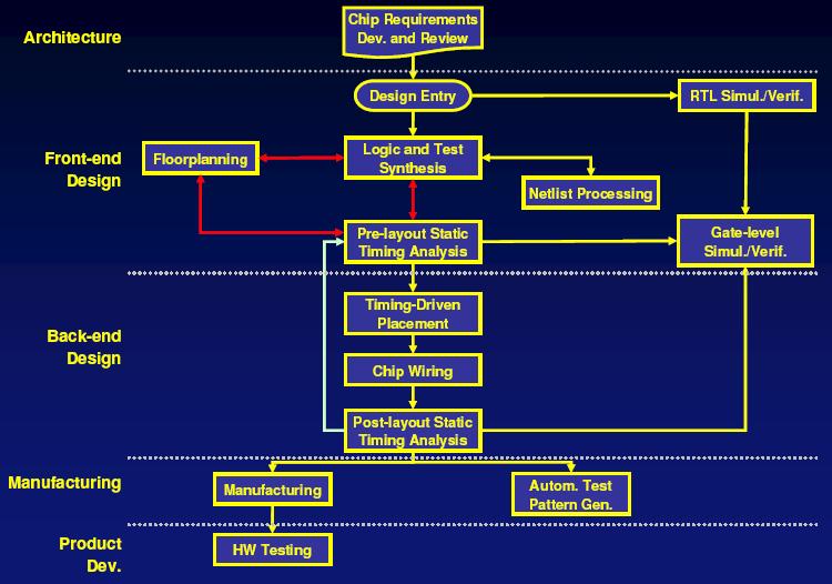
37 Waterfall vs. Spiral Design Flow The traditional model for ASIC development is often called a waterfall model. The project transitions from phase to phase in a step function, never returning to the activities of the previous phase.
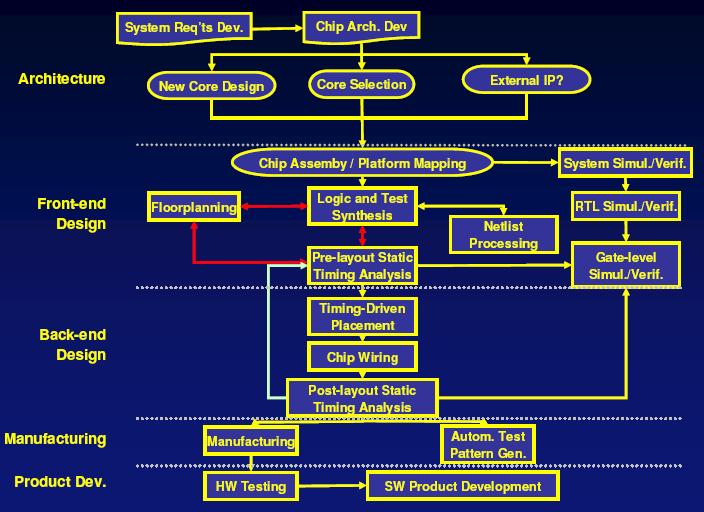
38 Waterfall vs. Spiral Design Flow As complexity increases, geometry shrinks, and time-to-market pressures continue to escalate, chip designers are moving from the old waterfall model to the newer spiral development model. In the spiral model, the design team works on multiple aspects of the design simultaneously, incrementally improving in each area as the design converges on completion. The spiral SoC design flow is characterized by: v Parallel, concurrent development of hardware and software v Parallel verification and synthesis of modules v Floorplanning and place-and-route included in the synthesis process v Modules developed only if a pre-designed hard or soft macro is not available v Planned iteration throughout
39 Waterfall vs. Spiral Design Flow Spiral SoC Design Flow Goal: Maintain parallel interacting design flow
40 Top-Down vs. Bottom-Up The classic top-down design process can be viewed as a recursive routine that begins with specification and decomposition, and ends with integration and verification: v Write complete specifications for the system or subsystem being designed. v Refine its architecture and algorithms, including software design and hardware/software cosimulation if necessary. v Decompose the architecture into well-defined macros. v Design or select macros; this is where the recursion occurs. v Integrate macros into the top level; verify functionality and timing. v Deliver the subsystem/system to the next higher level of integration; at the top level, this is tapeout. v Verify all aspects of the design (functionality, timing, etc.).
41 Top-Down vs. Bottom-Up A top-down methodology assumes that the lowest level blocks specified can, in fact, be designed and built. If it turns out that a block is not feasible to design, the whole specification process has to be repeated. For this reason, real world design teams usually use a mixture of top-down and bottom-up methodologies, building critical low-level blocks while they refine the system and block specifications. Libraries of reusable hard and soft macros clearly facilitate this process by providing a source of pre-verified blocks, proving that at least some parts of the design can be designed and fabricated in the target technology and perform to specification.
42 Design processes in flow diagrams The first part of the design process consists of recursively developing, verifying, and refining a set of specifications until they are detailed enough to allow RTL coding to begin. The specifications must completely describe all the interfaces between the design and its environment, including: v Hardware Functionality; External interfaces to other hardware (pins, buses, and how to use them); Interface to SW (register definitions); Timing; Performance; Physical design issues such as area and power v Software Functionality; Timing; Performance; Interface to HW SW structure, kernel Type of of specifications: v Formal specifications the desired characteristics of the design are defined independently of any implementation. v Executable specifications are typically an abstract model for the hardware and/or software being specified, and currently more useful for describing functional behavior in most design situations.
43 The System Design Process Determining the optimal architecture (cost and performance) involves a set of complex decisions, such as: What goes in software and what goes in hardware What processor(s) to use, and how many What bus architecture is required to achieve the required system performance What memory architecture to use to reach an appropriate balance between power, area, and speed. Solution: modeling of several alternative architectures
44 ASIC Typical Design Steps Top Level Design Unit Block Design Unit Block Verification Integration and Synthesis Trial Netlists Timing Convergence & Verification System Level Verification Fabrication DVT Prep Typical ASIC design can take up to two years to complete ?? 5 8 DVT Time in Weeks Time to Mask order
45 SoC Typical Design Steps Top Level Design Unit Block Design Unit Block Verification Integration and Synthesis Trial Netlists Timing Convergence & Verification System Level Verification Fabrication DVT Prep DVT Time in Weeks Time to Mask order 33 With increasing Complexity of IC s and decreasing Geometry, IC Vendor steps of Placement, Layout and Fabrication are unlikely to be greatly reduced. In fact there is a greater risk that Timing Convergence steps will involve more iteration. Need to reduce time before Vendor Steps. Need to consider Layout issues up-front.
46 SoC Typical Design Steps Top Level Design Unit Block Design Unit Block Verification Integration and Synthesis Trial Netlists Timing Convergence & Verification System Level Verification Fabrication DVT Prep DVT Time in Weeks Time to Mask order SoC Architecture already defined. Flexible to scale in frequency and complexity. Allows new IP cores, new technology to be integrated. Separate the design of the reusable IP from the design of the SoC. Build the SoC from library of tested IP. Unit design consists only of any additional core features or wrapping new IP to enable integration. Reusable IP purchased from external sources, developed from in-house designs or designed as separate project off critical SoC development path.

47 Design Methodology A Front-End ASIC Design Flow

48 Design Methodology A Back-End Design Flow or Generic Physical Flow.
49 ASIC Methodology
50 SOC Methodology

51 SOC Methodology Evolving...

52 How to Design an SOC

53 How to Design an SOC

54 How to Design an SOC

55 How to Design an SOC

56 How to Design an SOC
57 System on Chip - Testing SOCs are complex designs combining logic, memory and mixed-signal circuits in a single IC I/O pads CPU core Memory array Legacy core IP hard core I/O pads User-defined logic Self-test control DSP core Interface control TAP controller Embedded DRAM I/O pads Main SOC testing challenges Core level test: Embedded cores are tested as a part of the system Test access: Due to absence of physical access to the core peripheries, electronic access mechanism required SOC level test: SOC test is a single composite test including individual core, and UDL test and test scheduling Test data volume for core-based SOC designs is very high. New techniques are required to reduce testing time, test cost, and the memory requirements of the automatic test equipment (ATE)
58 Verification Today about 70% of design cost and effort is spent on verification. Verification teams are often almost twice as large as the RTL designers at companies developing ICs. Traditionally, chip design verification focuses on simulation. However, new verification techniques are emerging.
59 Design for Integration A key issue in SOC design is integration of silicon IPs (cores). Integration of IPs directly affects the complexity of SOC designs and also influences verification of the SOC. Verification is faster and easier if the SOC interconnect is simple and unified (use an on-chip communication system or intelligent on-chip bus). There is no standard for OCBs; they are chosen almost exclusively by the specific application for which they will be used and by the designer's preference. Two main types of OCBs (on-chip bus) and their characteristics OCB Speed Bandwidth Arbitration Example System High High Complex ARM AHB Peripheral Low Low Simple PCI Bus

60 A Typical Gateway SoC Architecture An example of typical gateway VoIP (Voice over Internet Protocol) system-on-a-chip diagram. A gateway VoIP SoC is a device used for functions such as vocoders, echo cancellation, data/fax modems, and VoIP protocols.
61 A Traditional SOC Architecture (bus-based) In a typical SOC, there are complex data flows and multiple cores such as CPUs, DSPs, DMA, and peripherals. Therefore, resource sharing becomes an issue, communication between IPs becomes very complicated.
62 Sonics SiliconBackplane Used in SOC Design Architecture The CPU, DMA, and the DSP engine all share the same bus (the CPU or the system bus). Also, there are dedicated data links, a lot of control wires between blocks, and peripheral buses between subsystems there is interdependency between blocks and a lot of wires in the chip. Therefore, verification, test, and physical design all become difficult to fulfill. A solution to this system integration is to use an intelligent, on-chip interconnect that unifies all the traffic into a single entity. An example of this is Sonics SMART Interconnect SiliconBackplane MicroNetwork. When compared to a traditional CPU bus, an on-chip interconnect such as Sonics SiliconBackplane has the following advantages: v Higher efficiency v Flexible configuration v Guaranteed bandwidth and latency v Integrated arbitration

63 Sonics SiliconBackplane MicroNetwork Used in SOC Design Architecture A MicroNetwork is a heterogeneous, integrated network that unifies, decouples, and manages all of the communication between processors, memories, and input/output devices.
, a sensor interface with a signal conditioner and two")
 with on-chip low-leakage memory, several timebasis and digital interfaces,")
64 The basic WiseNET SoC architecture The architecture includes: the ultralow-power dual-band radio transceiver (Tx and Rx), a sensor interface with a signal conditioner and two analog-to-digital converters (ANA_FE), a digital control unit based on a Cool-RISC microcontroller (µc) with on-chip low-leakage memory, several timebasis and digital interfaces, a power management block (POW)

65 Networks on a chip

66 SoC for DVB

67 Network Processor

68 Conclusions An System on Chip (SoC) is an integrated circuit that implements most or all of the function of a complete electronic system. Four vital areas of SoC: v v v v Higher levels of abstraction IP and platform re-use IP creation ASIPs, interconnect and algorithm Earlier software development and integration
Introduction to System-on-Chip
 Introduction to System-on-Chip COE838: Systems-on-Chip Design http://www.ee.ryerson.ca/~courses/coe838/ Dr. Gul N. Khan http://www.ee.ryerson.ca/~gnkhan Electrical and Computer Engineering Ryerson University
IP CORE Design 矽智產設計. C. W. Jen 任建葳.
 IP CORE Design 矽智產設計 C. W. Jen 任建葳 cwjen@twins.ee.nctu.edu.tw Course Contents Introduction to SoC and IP ARM processor core and instruction sets VCI interface, on-chip bus, and platform-based design IP
VLSI Design Automation
 VLSI Design Automation IC Products Processors CPU, DSP, Controllers Memory chips RAM, ROM, EEPROM Analog Mobile communication, audio/video processing Programmable PLA, FPGA Embedded systems Used in cars,
Hardware Software Codesign of Embedded Systems
 Hardware Software Codesign of Embedded Systems Rabi Mahapatra Texas A&M University Today s topics Course Organization Introduction to HS-CODES Codesign Motivation Some Issues on Codesign of Embedded System
Chapter 5: ASICs Vs. PLDs
 Chapter 5: ASICs Vs. PLDs 5.1 Introduction A general definition of the term Application Specific Integrated Circuit (ASIC) is virtually every type of chip that is designed to perform a dedicated task.
VLSI Design Automation. Maurizio Palesi
 VLSI Design Automation 1 Outline Technology trends VLSI Design flow (an overview) 2 Outline Technology trends VLSI Design flow (an overview) 3 IC Products Processors CPU, DSP, Controllers Memory chips
A VARIETY OF ICS ARE POSSIBLE DESIGNING FPGAS & ASICS. APPLICATIONS MAY USE STANDARD ICs or FPGAs/ASICs FAB FOUNDRIES COST BILLIONS
 architecture behavior of control is if left_paddle then n_state
VLSI Design Automation
 VLSI Design Automation IC Products Processors CPU, DSP, Controllers Memory chips RAM, ROM, EEPROM Analog Mobile communication, audio/video processing Programmable PLA, FPGA Embedded systems Used in cars,
VLSI Design Automation. Calcolatori Elettronici Ing. Informatica
 VLSI Design Automation 1 Outline Technology trends VLSI Design flow (an overview) 2 IC Products Processors CPU, DSP, Controllers Memory chips RAM, ROM, EEPROM Analog Mobile communication, audio/video processing
Hardware Software Codesign of Embedded System
 Hardware Software Codesign of Embedded System CPSC489-501 Rabi Mahapatra Mahapatra - Texas A&M - Fall 00 1 Today s topics Course Organization Introduction to HS-CODES Codesign Motivation Some Issues on
Digital Design Methodology (Revisited) Design Methodology: Big Picture
 Design Methodology: Big Picture") Digital Design Methodology (Revisited) Design Methodology Design Specification Verification Synthesis Technology Options Full Custom VLSI Standard Cell ASIC FPGA CS 150 Fall 2005 - Lec #25 Design Methodology
Digital Design Methodology (Revisited) Design Methodology Design Specification Verification Synthesis Technology Options Full Custom VLSI Standard Cell ASIC FPGA CS 150 Fall 2005 - Lec #25 Design Methodology
Digital Design Methodology
 Digital Design Methodology Prof. Soo-Ik Chae Digital System Designs and Practices Using Verilog HDL and FPGAs @ 2008, John Wiley 1-1 Digital Design Methodology (Added) Design Methodology Design Specification
SYSTEMS ON CHIP (SOC) FOR EMBEDDED APPLICATIONS
 FOR EMBEDDED APPLICATIONS") SYSTEMS ON CHIP (SOC) FOR EMBEDDED APPLICATIONS Embedded System System Set of components needed to perform a function Hardware + software +. Embedded Main function not computing Usually not autonomous
SYSTEMS ON CHIP (SOC) FOR EMBEDDED APPLICATIONS Embedded System System Set of components needed to perform a function Hardware + software +. Embedded Main function not computing Usually not autonomous
ECE 448 Lecture 15. Overview of Embedded SoC Systems
 ECE 448 Lecture 15 Overview of Embedded SoC Systems ECE 448 FPGA and ASIC Design with VHDL George Mason University Required Reading P. Chu, FPGA Prototyping by VHDL Examples Chapter 8, Overview of Embedded
Overview of Digital Design with Verilog HDL 1
 Overview of Digital Design with Verilog HDL 1 1.1 Evolution of Computer-Aided Digital Design Digital circuit design has evolved rapidly over the last 25 years. The earliest digital circuits were designed
Lab. Course Goals. Topics. What is VLSI design? What is an integrated circuit? VLSI Design Cycle. VLSI Design Automation
 Course Goals Lab Understand key components in VLSI designs Become familiar with design tools (Cadence) Understand design flows Understand behavioral, structural, and physical specifications Be able to
Testable SOC Design. Sungho Kang
 Testable SOC Design Sungho Kang 2001.10.5 Outline Introduction SOC Test Challenges IEEE P1500 SOC Test Strategies Conclusion 2 SOC Design Evolution Emergence of very large transistor counts on a single
Introduction to Embedded Systems
 Introduction to Embedded Systems Outline Embedded systems overview What is embedded system Characteristics Elements of embedded system Trends in embedded system Design cycle 2 Computing Systems Most of
Design Solutions in Foundry Environment. by Michael Rubin Agilent Technologies
 Design Solutions in Foundry Environment by Michael Rubin Agilent Technologies Presenter: Michael Rubin RFIC Engineer, R&D, Agilent Technologies former EDA Engineering Manager Agilent assignee at Chartered
Hardware/Software Co-design
 Hardware/Software Co-design Zebo Peng, Department of Computer and Information Science (IDA) Linköping University Course page: http://www.ida.liu.se/~petel/codesign/ 1 of 52 Lecture 1/2: Outline : an Introduction
More Course Information
 More Course Information Labs and lectures are both important Labs: cover more on hands-on design/tool/flow issues Lectures: important in terms of basic concepts and fundamentals Do well in labs Do well
COE 561 Digital System Design & Synthesis Introduction
 1 COE 561 Digital System Design & Synthesis Introduction Dr. Aiman H. El-Maleh Computer Engineering Department King Fahd University of Petroleum & Minerals Outline Course Topics Microelectronics Design
Hardware-Software Codesign. 1. Introduction
 Hardware-Software Codesign 1. Introduction Lothar Thiele 1-1 Contents What is an Embedded System? Levels of Abstraction in Electronic System Design Typical Design Flow of Hardware-Software Systems 1-2
Hardware Description Languages. Introduction to VHDL
 Hardware Description Languages Introduction to VHDL 1 What does VHDL stand for? VHSIC (= Very High Speed Integrated Circuit) Hardware Description Language 2 Others HDL VHDL IEEE Std 1076-1993 Verilog IEEE
Choosing an Intellectual Property Core
 Choosing an Intellectual Property Core MIPS Technologies, Inc. June 2002 One of the most important product development decisions facing SOC designers today is choosing an intellectual property (IP) core.
DIGITAL DESIGN TECHNOLOGY & TECHNIQUES
 DIGITAL DESIGN TECHNOLOGY & TECHNIQUES CAD for ASIC Design 1 INTEGRATED CIRCUITS (IC) An integrated circuit (IC) consists complex electronic circuitries and their interconnections. William Shockley et
EEM870 Embedded System and Experiment Lecture 4: SoC Design Flow and Tools
 EEM870 Embedded System and Experiment Lecture 4: SoC Design Flow and Tools Wen-Yen Lin, Ph.D. Department of Electrical Engineering Chang Gung University Email: wylin@mail.cgu.edu.tw March 2013 Agenda Introduction
Part 2: Principles for a System-Level Design Methodology
 Part 2: Principles for a System-Level Design Methodology Separation of Concerns: Function versus Architecture Platform-based Design 1 Design Effort vs. System Design Value Function Level of Abstraction
Spiral 2-8. Cell Layout
 2-8.1 Spiral 2-8 Cell Layout 2-8.2 Learning Outcomes I understand how a digital circuit is composed of layers of materials forming transistors and wires I understand how each layer is expressed as geometric
EE586 VLSI Design. Partha Pande School of EECS Washington State University
 EE586 VLSI Design Partha Pande School of EECS Washington State University pande@eecs.wsu.edu Lecture 1 (Introduction) Why is designing digital ICs different today than it was before? Will it change in
IMPLEMENTATION OF LOW POWER INTERFACE FOR VERIFICATION IP (VIP) OF AXI4 PROTOCOL
 OF AXI4 PROTOCOL") e-issn 2455 1392 Volume 2 Issue 8, August 2016 pp. 1 8 Scientific Journal Impact Factor : 3.468 http://www.ijcter.com IMPLEMENTATION OF LOW POWER INTERFACE FOR VERIFICATION IP (VIP) OF AXI4 PROTOCOL Bhavana
e-issn 2455 1392 Volume 2 Issue 8, August 2016 pp. 1 8 Scientific Journal Impact Factor : 3.468 http://www.ijcter.com IMPLEMENTATION OF LOW POWER INTERFACE FOR VERIFICATION IP (VIP) OF AXI4 PROTOCOL Bhavana
Model-Based Design for effective HW/SW Co-Design Alexander Schreiber Senior Application Engineer MathWorks, Germany
 Model-Based Design for effective HW/SW Co-Design Alexander Schreiber Senior Application Engineer MathWorks, Germany 2013 The MathWorks, Inc. 1 Agenda Model-Based Design of embedded Systems Software Implementation
ECE 637 Integrated VLSI Circuits. Introduction. Introduction EE141
 ECE 637 Integrated VLSI Circuits Introduction EE141 1 Introduction Course Details Instructor Mohab Anis; manis@vlsi.uwaterloo.ca Text Digital Integrated Circuits, Jan Rabaey, Prentice Hall, 2 nd edition
Hardware Design Environments. Dr. Mahdi Abbasi Computer Engineering Department Bu-Ali Sina University
 Hardware Design Environments Dr. Mahdi Abbasi Computer Engineering Department Bu-Ali Sina University Outline Welcome to COE 405 Digital System Design Design Domains and Levels of Abstractions Synthesis
Intro to High Level Design with SystemC
 Intro to High Level Design with SystemC Aim To introduce SystemC, and its associated Design Methodology Date 26th March 2001 Presented By Alan Fitch Designer Challenges Design complexity System on Chip
Digital System Design Lecture 2: Design. Amir Masoud Gharehbaghi
 Digital System Design Lecture 2: Design Amir Masoud Gharehbaghi amgh@mehr.sharif.edu Table of Contents Design Methodologies Overview of IC Design Flow Hardware Description Languages Brief History of HDLs
System-on-Chip Architecture for Mobile Applications. Sabyasachi Dey
 System-on-Chip Architecture for Mobile Applications Sabyasachi Dey Email: sabyasachi.dey@gmail.com Agenda What is Mobile Application Platform Challenges Key Architecture Focus Areas Conclusion Mobile Revolution
Supporting Advanced-Node FinFET SoCs with 16Gbps Multi-Protocol SerDes PHY IP
 Supporting Advanced-Node FinFET SoCs with 16Gbps Multi-Protocol IP By William Chen and Osman Javed, Cadence Design Systems Applications such as the Internet of Things, cloud computing, and high-definition
System Design and Methodology/ Embedded Systems Design (Modeling and Design of Embedded Systems)
") Design&Methodologies Fö 1&2-1 Design&Methodologies Fö 1&2-2 Course Information Design and Methodology/ Embedded s Design (Modeling and Design of Embedded s) TDTS07/TDDI08 Web page: http://www.ida.liu.se/~tdts07
Design&Methodologies Fö 1&2-1 Design&Methodologies Fö 1&2-2 Course Information Design and Methodology/ Embedded s Design (Modeling and Design of Embedded s) TDTS07/TDDI08 Web page: http://www.ida.liu.se/~tdts07
Hardware-Software Codesign. 1. Introduction
 Hardware-Software Codesign 1. Introduction Lothar Thiele 1-1 Contents What is an Embedded System? Levels of Abstraction in Electronic System Design Typical Design Flow of Hardware-Software Systems 1-2
ASIC, Customer-Owned Tooling, and Processor Design
 ASIC, Customer-Owned Tooling, and Processor Design Design Style Myths That Lead EDA Astray Nancy Nettleton Manager, VLSI ASIC Device Engineering April 2000 Design Style Myths COT is a design style that
Cover TBD. intel Quartus prime Design software
 Cover TBD intel Quartus prime Design software Fastest Path to Your Design The Intel Quartus Prime software is revolutionary in performance and productivity for FPGA, CPLD, and SoC designs, providing a
CONSIDERATIONS FOR THE DESIGN OF A REUSABLE SOC HARDWARE/SOFTWARE
 1 2 3 CONSIDERATIONS FOR THE DESIGN OF A REUSABLE SOC HARDWARE/SOFTWARE DEVELOPMENT BOARD Authors: Jonah Probell and Andy Young, design engineers, Lexra, Inc. 4 5 6 7 8 9 A Hardware/Software Development
Long Term Trends for Embedded System Design
 Long Term Trends for Embedded System Design Ahmed Amine JERRAYA Laboratoire TIMA, 46 Avenue Félix Viallet, 38031 Grenoble CEDEX, France Email: Ahmed.Jerraya@imag.fr Abstract. An embedded system is an application
Optimizing ARM SoC s with Carbon Performance Analysis Kits. ARM Technical Symposia, Fall 2014 Andy Ladd
 Optimizing ARM SoC s with Carbon Performance Analysis Kits ARM Technical Symposia, Fall 2014 Andy Ladd Evolving System Requirements Processor Advances big.little Multicore Unicore DSP Cortex -R7 Block
System Level Design with IBM PowerPC Models
 September 2005 System Level Design with IBM PowerPC Models A view of system level design SLE-m3 The System-Level Challenges Verification escapes cost design success There is a 45% chance of committing
Design of DMA Controller Using VHDL
 Design of DMA Controller Using VHDL Rashmi mishra 1, Rupal chauhan 2, Garima arora 3 1, 2 Department of Electronics & Communication BE (VII SEM) Takshshila Institute of Engineering & Technology, Jabalpur,
Introduction. Definition. What is an embedded system? What are embedded systems? Challenges in embedded computing system design. Design methodologies.
 Introduction What are embedded systems? Challenges in embedded computing system design. Design methodologies. What is an embedded system? Communication Avionics Automobile Consumer Electronics Office Equipment
FPGA Based Digital Design Using Verilog HDL
 FPGA Based Digital Design Using Course Designed by: IRFAN FAISAL MIR ( Verilog / FPGA Designer ) irfanfaisalmir@yahoo.com * Organized by Electronics Division Integrated Circuits Uses for digital IC technology
CHAPTER 1 INTRODUCTION
 CHAPTER 1 INTRODUCTION Rapid advances in integrated circuit technology have made it possible to fabricate digital circuits with large number of devices on a single chip. The advantages of integrated circuits
Platform for System LSI Development
 Platform for System LSI Development Hitachi Review Vol. 50 (2001), No. 2 45 SOCplanner : Reducing Time and Cost in Developing Systems Tsuyoshi Shimizu Yoshio Okamura Yoshimune Hagiwara Akihisa Uchida OVERVIEW:
High Performance Mixed-Signal Solutions from Aeroflex
 High Performance Mixed-Signal Solutions from Aeroflex We Connect the REAL World to the Digital World Solution-Minded Performance-Driven Customer-Focused Aeroflex (NASDAQ:ARXX) Corporate Overview Diversified
Park Sung Chul. AE MentorGraphics Korea
 PGA Design rom Concept to Silicon Park Sung Chul AE MentorGraphics Korea The Challenge of Complex Chip Design ASIC Complex Chip Design ASIC or FPGA? N FPGA Design FPGA Embedded Core? Y FPSoC Design Considerations
Dr. Ajoy Bose. SoC Realization Building a Bridge to New Markets and Renewed Growth. Chairman, President & CEO Atrenta Inc.
 SoC Realization Building a Bridge to New Markets and Renewed Growth Dr. Ajoy Bose Chairman, President & CEO Atrenta Inc. October 20, 2011 2011 Atrenta Inc. SoCs Are Driving Electronic Product Innovation
Trend in microelectronics The design process and tasks Different design paradigms Basic terminology The test problems
 Electronics Systems Trend in microelectronics The design process and tasks Different design paradigms Basic terminology The test problems The Technological Trend # of trans. 100M 75M 50M Moore s Law (#
Design Metrics. A couple of especially important metrics: Time to market Total cost (NRE + unit cost) Performance (speed latency and throughput)
 Performance (speed latency and throughput)") Design Metrics A couple of especially important metrics: Time to market Total cost (NRE + unit cost) Performance (speed latency and throughput) 1 Design Metrics A couple of especially important metrics:
Design Metrics A couple of especially important metrics: Time to market Total cost (NRE + unit cost) Performance (speed latency and throughput) 1 Design Metrics A couple of especially important metrics:
Cover TBD. intel Quartus prime Design software
 Cover TBD intel Quartus prime Design software Fastest Path to Your Design The Intel Quartus Prime software is revolutionary in performance and productivity for FPGA, CPLD, and SoC designs, providing a
Mapping Multi-Million Gate SoCs on FPGAs: Industrial Methodology and Experience
 Mapping Multi-Million Gate SoCs on FPGAs: Industrial Methodology and Experience H. Krupnova CMG/FMVG, ST Microelectronics Grenoble, France Helena.Krupnova@st.com Abstract Today, having a fast hardware
Using ASIC circuits. What is ASIC. ASIC examples ASIC types and selection ASIC costs ASIC purchasing Trends in IC technologies
 Using ASIC circuits What is this machine? ASIC examples ASIC types and selection ASIC ASIC purchasing Trends in IC technologies 9.3.2004 Turo Piila 1 9.3.2004 Turo Piila 2 What is ASIC Floorplan and layout
Silicon Virtual Prototyping: The New Cockpit for Nanometer Chip Design
 Silicon Virtual Prototyping: The New Cockpit for Nanometer Chip Design Wei-Jin Dai, Dennis Huang, Chin-Chih Chang, Michel Courtoy Cadence Design Systems, Inc. Abstract A design methodology for the implementation
Design and Technology Trends
 Lecture 1 Design and Technology Trends R. Saleh Dept. of ECE University of British Columbia res@ece.ubc.ca 1 Recently Designed Chips Itanium chip (Intel), 2B tx, 700mm 2, 8 layer 65nm CMOS (4 processors)
Cluster-based approach eases clock tree synthesis
 Page 1 of 5 EE Times: Design News Cluster-based approach eases clock tree synthesis Udhaya Kumar (11/14/2005 9:00 AM EST) URL: http://www.eetimes.com/showarticle.jhtml?articleid=173601961 Clock network
Design Methodologies
 Design Methodologies 1981 1983 1985 1987 1989 1991 1993 1995 1997 1999 2001 2003 2005 2007 2009 Complexity Productivity (K) Trans./Staff - Mo. Productivity Trends Logic Transistor per Chip (M) 10,000 0.1
For a long time, programming languages such as FORTRAN, PASCAL, and C Were being used to describe computer programs that were
 CHAPTER-2 HARDWARE DESCRIPTION LANGUAGES 2.1 Overview of HDLs : For a long time, programming languages such as FORTRAN, PASCAL, and C Were being used to describe computer programs that were sequential
EITF35: Introduction to Structured VLSI Design
 EITF35: Introduction to Structured VLSI Design Part 1.1.2: Introduction (Digital VLSI Systems) Liang Liu liang.liu@eit.lth.se 1 Outline Why Digital? History & Roadmap Device Technology & Platforms System
AMS Behavioral Modeling
 CHAPTER 3 AMS Behavioral Modeling Ronald S. Vogelsong, Ph.D. Overview Analog designers have for many decades developed their design using a Bottom-Up design flow. First, they would gain the necessary understanding
Case study of Mixed Signal Design Flow
 IOSR Journal of VLSI and Signal Processing (IOSR-JVSP) Volume 6, Issue 3, Ver. II (May. -Jun. 2016), PP 49-53 e-issn: 2319 4200, p-issn No. : 2319 4197 www.iosrjournals.org Case study of Mixed Signal Design
Computer Architecture s Changing Definition
 Computer Architecture s Changing Definition 1950s Computer Architecture Computer Arithmetic 1960s Operating system support, especially memory management 1970s to mid 1980s Computer Architecture Instruction
ECE 486/586. Computer Architecture. Lecture # 2
 ECE 486/586 Computer Architecture Lecture # 2 Spring 2015 Portland State University Recap of Last Lecture Old view of computer architecture: Instruction Set Architecture (ISA) design Real computer architecture:
EE 466/586 VLSI Design. Partha Pande School of EECS Washington State University
 EE 466/586 VLSI Design Partha Pande School of EECS Washington State University pande@eecs.wsu.edu Lecture 18 Implementation Methods The Design Productivity Challenge Logic Transistors per Chip (K) 10,000,000.10m
Design Methodologies. Kai Huang
 Design Methodologies Kai Huang News Is that real? In such a thermally constrained environment, going quad-core only makes sense if you can properly power gate/turbo up when some cores are idle. I have
The Use Of Virtual Platforms In MP-SoC Design. Eshel Haritan, VP Engineering CoWare Inc. MPSoC 2006
 The Use Of Virtual Platforms In MP-SoC Design Eshel Haritan, VP Engineering CoWare Inc. MPSoC 2006 1 MPSoC Is MP SoC design happening? Why? Consumer Electronics Complexity Cost of ASIC Increased SW Content
l Some materials from various sources! Soma 1! l Apply a signal, measure output, compare l 32-bit adder test example:!
 Acknowledgements! Introduction and Overview! Mani Soma! l Some materials from various sources! n Dr. Phil Nigh, IBM! n Principles of Testing Electronic Systems by S. Mourad and Y. Zorian! n Essentials
ARM Processors for Embedded Applications
 ARM Processors for Embedded Applications Roadmap for ARM Processors ARM Architecture Basics ARM Families AMBA Architecture 1 Current ARM Core Families ARM7: Hard cores and Soft cores Cache with MPU or
E 4.20 Introduction to Digital Integrated Circuit Design
 E 4.20 Introduction to Digital Integrated Circuit Design Peter Cheung Department of Electrical & Electronic Engineering Imperial College London URL: www.ee.ic.ac.uk/pcheung/ E-mail: p.cheung@imperial.ac.uk
Mentor Graphics Solutions Enable Fast, Efficient Designs for Altera s FPGAs. Fall 2004
 Mentor Graphics Solutions Enable Fast, Efficient Designs for Altera s FPGAs Fall 2004 Agenda FPGA design challenges Mentor Graphics comprehensive FPGA design solutions Unique tools address the full range
Embedded Systems Dr. Santanu Chaudhury Department of Electrical Engineering Indian Institute of Technology, Delhi. Lecture - 10 System on Chip (SOC)
") Embedded Systems Dr. Santanu Chaudhury Department of Electrical Engineering Indian Institute of Technology, Delhi Lecture - 10 System on Chip (SOC) In the last class, we had discussed digital signal processors.
Embedded Systems Dr. Santanu Chaudhury Department of Electrical Engineering Indian Institute of Technology, Delhi Lecture - 10 System on Chip (SOC) In the last class, we had discussed digital signal processors.
Moore s Law: Alive and Well. Mark Bohr Intel Senior Fellow
 Moore s Law: Alive and Well Mark Bohr Intel Senior Fellow Intel Scaling Trend 10 10000 1 1000 Micron 0.1 100 nm 0.01 22 nm 14 nm 10 nm 10 0.001 1 1970 1980 1990 2000 2010 2020 2030 Intel Scaling Trend
RTL Coding General Concepts
 RTL Coding General Concepts Typical Digital System 2 Components of a Digital System Printed circuit board (PCB) Embedded d software microprocessor microcontroller digital signal processor (DSP) ASIC Programmable
Microelettronica. J. M. Rabaey, "Digital integrated circuits: a design perspective" EE141 Microelettronica
 Microelettronica J. M. Rabaey, "Digital integrated circuits: a design perspective" Introduction Why is designing digital ICs different today than it was before? Will it change in future? The First Computer
Embedded Quality for Test. Yervant Zorian LogicVision, Inc.
 Embedded Quality for Test Yervant Zorian LogicVision, Inc. Electronics Industry Achieved Successful Penetration in Diverse Domains Electronics Industry (cont( cont) Met User Quality Requirements satisfying
EEM870 Embedded System and Experiment Lecture 2: Introduction to SoC Design
 EEM870 Embedded System and Experiment Lecture 2: Introduction to SoC Design Wen-Yen Lin, Ph.D. Department of Electrical Engineering Chang Gung University Email: wylin@mail.cgu.edu.tw March 2013 Agenda
Functional Programming in Hardware Design
 Functional Programming in Hardware Design Tomasz Wegrzanowski Saarland University Tomasz.Wegrzanowski@gmail.com 1 Introduction According to the Moore s law, hardware complexity grows exponentially, doubling
Eliminating Routing Congestion Issues with Logic Synthesis
 Eliminating Routing Congestion Issues with Logic Synthesis By Mike Clarke, Diego Hammerschlag, Matt Rardon, and Ankush Sood Routing congestion, which results when too many routes need to go through an
FPGA BASED SYSTEM DESIGN. Dr. Tayab Din Memon Lecture 1 & 2
 FPGA BASED SYSTEM DESIGN Dr. Tayab Din Memon tayabuddin.memon@faculty.muet.edu.pk Lecture 1 & 2 Books Recommended Books: Text Book: FPGA Based System Design by Wayne Wolf Verilog HDL by Samir Palnitkar.
CAN on Integration Technologies
 CAN on Integration Technologies CAN technology has reached the mature state where the powerful network technology is well covered by standard parts; mainly processors with integrated CAN periphery. Nevertheless
CAD for VLSI. Debdeep Mukhopadhyay IIT Madras
 CAD for VLSI Debdeep Mukhopadhyay IIT Madras Tentative Syllabus Overall perspective of VLSI Design MOS switch and CMOS, MOS based logic design, the CMOS logic styles, Pass Transistors Introduction to Verilog
IMPROVES. Initial Investment is Low Compared to SoC Performance and Cost Benefits
 NOC INTERCONNECT IMPROVES SOC ECONO CONOMICS Initial Investment is Low Compared to SoC Performance and Cost Benefits A s systems on chip (SoCs) have interconnect, along with its configuration, verification,
Navigating the RTL to System Continuum
 Navigating the RTL to System Continuum Calypto Design Systems, Inc. www.calypto.com Copyright 2005 Calypto Design Systems, Inc. - 1 - The rapidly evolving semiconductor industry has always relied on innovation
DFT Trends in the More than Moore Era. Stephen Pateras Mentor Graphics
 DFT Trends in the More than Moore Era Stephen Pateras Mentor Graphics steve_pateras@mentor.com Silicon Valley Test Conference 2011 1 Outline Semiconductor Technology Trends DFT in relation to: Increasing
Emerging Platforms, Emerging Technologies, and the Need for Crosscutting Tools Luca Carloni
 Emerging Platforms, Emerging Technologies, and the Need for Crosscutting Tools Luca Carloni Department of Computer Science Columbia University in the City of New York NSF Workshop on Emerging Technologies
Introduction. Summary. Why computer architecture? Technology trends Cost issues
 Introduction 1 Summary Why computer architecture? Technology trends Cost issues 2 1 Computer architecture? Computer Architecture refers to the attributes of a system visible to a programmer (that have
What is this class all about?
 EE141-Fall 2007 Digital Integrated Circuits Instructor: Elad Alon TuTh 3:30-5pm 155 Donner 1 1 What is this class all about? Introduction to digital integrated circuit design engineering Will describe
Ten Reasons to Optimize a Processor
 By Neil Robinson SoC designs today require application-specific logic that meets exacting design requirements, yet is flexible enough to adjust to evolving industry standards. Optimizing your processor
Modeling and Simulation of System-on. Platorms. Politecnico di Milano. Donatella Sciuto. Piazza Leonardo da Vinci 32, 20131, Milano
 Modeling and Simulation of System-on on-chip Platorms Donatella Sciuto 10/01/2007 Politecnico di Milano Dipartimento di Elettronica e Informazione Piazza Leonardo da Vinci 32, 20131, Milano Key SoC Market
EE382V: System-on-a-Chip (SoC) Design
 Design") EE382V: System-on-a-Chip (SoC) Design Lecture 8 HW/SW Co-Design Sources: Prof. Margarida Jacome, UT Austin Andreas Gerstlauer Electrical and Computer Engineering University of Texas at Austin gerstl@ece.utexas.edu
EE382V: System-on-a-Chip (SoC) Design Lecture 8 HW/SW Co-Design Sources: Prof. Margarida Jacome, UT Austin Andreas Gerstlauer Electrical and Computer Engineering University of Texas at Austin gerstl@ece.utexas.edu
Chapter 1 Overview of Digital Systems Design
 Chapter 1 Overview of Digital Systems Design SKEE2263 Digital Systems Mun im/ismahani/izam {munim@utm.my,e-izam@utm.my,ismahani@fke.utm.my} February 8, 2017 Why Digital Design? Many times, microcontrollers
White Paper. The Case for Developing Custom Analog. Custom analog SoCs - real option for more product managers.
 The Case for Developing Custom Analog Custom analog SoCs - real option for more product managers. White Paper The contents of this document are owned or controlled by S3 Group and are protected under applicable
ASYNC Rik van de Wiel COO Handshake Solutions
 ASYNC 2006 Rik van de Wiel COO Handshake Solutions Outline Introduction to Handshake Solutions Applications Design Tools ARM996HS Academic Program Handshake Solutions Started as research project in Philips
ASIC world. Start Specification Design Verification Layout Validation Finish
 AMS Verification Agenda ASIC world ASIC Industrial Facts Why Verification? Verification Overview Functional Verification Formal Verification Analog Verification Mixed-Signal Verification DFT Verification