Disassembly Procedure
|
|
|
- Tamsin Harrington
- 5 years ago
- Views:
Transcription
1 Chapter 2 Disassembly Procedure Please follow the information provided in this section to perform the complete disassembly procedure of the Eee PC 1201HA. Be sure to use proper tools described before. ASUS Eee PC 1201HA consists of various modules. This chapter describes the procedures for the complete Eee PC 1201HA disassembly. In addition, in between procedures, the detailed disassembly procedure of individual modules will be provided for your service needs. The disassembly procedure consists of the following steps: Battery Module Memory Module Keyboard Module Top Case Module HDD Module IO Board Module WLAN Module Motherboard Module Bottom Case Module LCD Module 2-1


2 B A T T E R Y B A T T E R Y R E M O V A L Battery Module The illustration below shows how to remove the battery module. Remove battery module 1. Unlock latch 1 towards the direction of arrow and then unlock and hold the latch 2 to remove the battery. TOP M E M O R Y M O D U L E M E M O R Y R E M O V A L Memory Module The illustration shows how to remove the memory module form the Eee PC 1201HA. Removing Memory module 1. Remove 2 screws here and take the memory cover away. 2-2


3 2. Uncover the Mylar here. 3. Softly open the two latches to pop the memory module up at 45 degree angles then remove the memory at that angle. TOP 2-3

 on")

4 K E Y B O A R D M O D U L E K E Y B O A R D M O D U L E Keyboard Module The illustration of below shows how to remove the keyboard Removing Keyboard 1. Push the 4 latches (Esc; F5; F11; Delete) on keyboard module to lift the keyboard plate. R E M O V A L 2. Place the keyboard plate on the top case. 2-4

5 3. Disconnect the keyboard FPC, and then take keyboard module away. Disassembly procedure TOP 2-5


6 T O P C A S E M O D U L E T O P C A S E R E M O V A L Top Case Module The illustrations below show how to disassemble and remove the top case module of the Eee PC 1201HA. The module contains the top case itself. Removing Top Case Module 1. Remove 10 screws on the top case and disconnect the touchpad FFC. 2-6


7 2. Remove 4 screws on the bottom case. 3. Softly pry the four sides of the system to open the latch hooks securing the top case with bottom case. 2-7


8 4. Uncover the Mylar here and disconnect the touchpad FFC. Then take it away. Disassembly procedure TOP 2-8


9 H D D M O D U L E H D D R E M O V A L HDD Module The illustration shows how to remove the HDD module form the Eee PC 1201HA. Removing HDD module 1. Remove 1 screw here and take the HDD module away. 2. Remove 4 screws here and remove the HDD from its bracket. 2-9
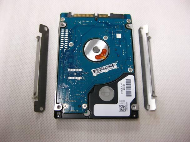
10 TOP 2-10


11 I O B O A R D M O D U L E IO B O A R D D R E M O V A L IO Board Module The illustration shows how to remove the IO Board module form the Eee PC 1201HA. Removing IO Board module 1. Remove the SD card from its slot. 2. Unlock 2 latches here and take the DAU FFC away. 3. Remove 1 screw here. 2-11


12 4. Turn over the IO board and disconnect the speaker cable. Then take the IO board away. TOP 2-12


13 W L A N M O D U L E W L A N R E M O V A L WLAN Module The illustration shows how to remove the WLAN module form the Eee PC 1201HA. Removing Memory module 1. Disconnect the WLAN antenna and remove 1 screw here, then take the WLAN module away. TOP M O T H E R B O A R D M O T H E R B R D D I S A S S E M B Y Motherboard Module The illustrations below show how to remove the motherboard module from the Eee PC 1201HA. Disassemble Motherboard 1. Remove 4 screws on the back of notebook and remove the top hinge covers. 2-13


14 2. Disconnect the LVDS cable, RJ45 CONNECTOR CABLE,CMOS cable, fan cable, Bluetooth cable with the motherboard and remove 2 screw here. 2-14


15 3. Prize up the BIOS battery and take the motherboard away. TOP B O T T O M C A S E M O D U L E Bottom Case Module The illustrations below show how to remove and disassemble the bottom case of the Eee PC 1201HA. Disassembling Bottom Case Module 1. Tear off the tape here and take the 1201HA_RJ45 CONNECTOR CABLE away. 2-15


16 2. Remove 3 screws here and take the fan module away. 3. Remove the Bluetooth on the bottom case. Then disconnect the Bluetooth cable. TOP 2-16


17 L C D M O D U L E L C D M O D U L E D I S A S S E M B L LCD Module The illustrations below show how to remove and disassemble the LCD module. The module contains LCD panel, Inverter board, LCD bezel, LCD back cover. Disassembling LCD Module 1. Tear off 1 piece of tape here and remove 2 screws on each hinge. Then remove the LCD module from the bottom case. 2-17


18 2. Remove 2 hinge covers. 3. Remove 6 rubber pads and 6 screws on LCD front bezel. 4. Pry the four inner sides of LCD front bezel and separate it from LCD module. 2-18


19 5. Remove 4 screws here and take the LCD hinge away. 6. Take the LCD panel away. 2-19


20 7. Disconnect the coaxial cable then take it away. 8. Remove 4 screws here and take the LCD brackets away. 2-20


21 9. Disconnect CMOS cable and take it away. 10. Take the camera away. TOP 2-21
Assembly Procedure. Chapter
 Chapter 3 Assembly Procedure Please follow the information provided in this section to perform the complete assembly procedure of the Eee PC 1101HA. Be sure to use proper tools described before. A fter
Disassembly Procedure
 Chapter 2 Disassembly Procedure Please follow the information provided in this section to perform the complete disassembly procedure of the notebook. Be sure to use proper tools described before. A SUS
Disassembly Procedure
 Chapter 2 Disassembly Procedure Please follow the information provided in this section to perform the complete disassembly procedure of the notebook. Be sure to use proper tools described before. A SUS
ASUS A2000 Series Notebook consists of various modules. This chapter
 Chapter 2 Disassembly Procedure Please follow the information provided in this section to perform the complete disassembly procedure of the notebook. Be sure to use proper tools described before. ASUS
Disassembly Procedure
 Chapter 2 Disassembly Procedure Please follow the information provided in this section to perform the complete disassembly procedure of the notebook. Be sure to use proper tools described before. SUS A7T
Disassembly Procedure
 Chapter 3 Disassembly Procedure Please follow the information provided in this section to perform the complete disassembly procedure of the notebook. Be sure to use proper tools described before. A SUS
Disassembly Procedure
 Chapter 3 Disassembly Procedure Please follow the information provided in this section to perform the complete disassembly procedure of the notebook. Be sure to use proper tools described before. A SUS
TravelMate 6493 Series Disassembly Instruction
 TravelMate 6493 Series Disassembly Instruction please refer to http://csd.acer.com.tw PRINTED IN TAIWAN Chapter 3 Machine Disassembly and Replacement This chapter contains step-by-step procedures on how
Upgrade & Replacement
 Chapter 4 Upgrade & Replacement Follow the individual procedures in this chapter to perform the notebook s upgrade and replacement of various major components. Z84Jc Series Notebook is a 2 spindles product,
EX310 (MS-1333)Disassemble SOP
Disassemble SOP") EX310 (MS-1333)Disassemble SOP 1 Battery Pack 2 BOTTOM DOOR ASSY 3 WLAN THERMAL-KIT And CPU Module 4 MDC And RAM Module 5 HDD Module ASSY 6 ODD Module ASSY 7 HINGE COVER ASSY 8 UP CASE ASSY 9 LOWER CASE
EX310 (MS-1333)Disassemble SOP 1 Battery Pack 2 BOTTOM DOOR ASSY 3 WLAN THERMAL-KIT And CPU Module 4 MDC And RAM Module 5 HDD Module ASSY 6 ODD Module ASSY 7 HINGE COVER ASSY 8 UP CASE ASSY 9 LOWER CASE
Disassembly Procedure
 Chapter 3 Disassembly Procedure Please follow the information provided in this section to perform the complete disassembly procedure of the notebook. Be sure to use proper tools described before. ASUS
GT735(MS-1721)Disassemble SOP
Disassemble SOP") 1 Battery Pack 2 BOTTOM DOOR ASSY 3 THERMAL-KIT And CPU Module 4 RAM TUNER And WLAN Module 5 HDD Module ASSY 6 ODD Module ASSY 7 HINGE COVER ASSY 8 UPPER CASE ASSY 9 LOWER CASE ASSY 10 LCD MODULE ASSY
1 Battery Pack 2 BOTTOM DOOR ASSY 3 THERMAL-KIT And CPU Module 4 RAM TUNER And WLAN Module 5 HDD Module ASSY 6 ODD Module ASSY 7 HINGE COVER ASSY 8 UPPER CASE ASSY 9 LOWER CASE ASSY 10 LCD MODULE ASSY
GX720 (MS-1722)Disassemble SOP
Disassemble SOP") GX720 (MS-1722)Disassemble SOP 1 Battery Pack 2 BOTTOM DOOR ASSY 3 THERMAL-KIT And CPU Module 4 RAM WLAN And TUNER Module 5 HDD Module ASSY 6 ODD Module ASSY 7 HINGE COVER ASSY 8 UP CASE ASSY 9 LOWER CASE
GX720 (MS-1722)Disassemble SOP 1 Battery Pack 2 BOTTOM DOOR ASSY 3 THERMAL-KIT And CPU Module 4 RAM WLAN And TUNER Module 5 HDD Module ASSY 6 ODD Module ASSY 7 HINGE COVER ASSY 8 UP CASE ASSY 9 LOWER CASE
KN1Series Notebook consists of various modules. This chapter describes
 Chapter 2 Disassembly Procedure Please follow the information provided in this section to perform the complete disassembly procedure of the notebook. Be sure to use proper tools described before. KNSeries
GX620 (MS-1651)Disassemble SOP
Disassemble SOP") GX620 (MS-1651)Disassemble SOP 1 Battery Pack 2 BOTTOM DOOR ASSY 3 THERMAL-KIT And CPU Module 4 RAM WLAN And TUNER Module 5 HDD Module ASSY 6 ODD Module ASSY 7 HINGE COVER ASSY 8 UP CASE ASSY 9 LOWER CASE
GX620 (MS-1651)Disassemble SOP 1 Battery Pack 2 BOTTOM DOOR ASSY 3 THERMAL-KIT And CPU Module 4 RAM WLAN And TUNER Module 5 HDD Module ASSY 6 ODD Module ASSY 7 HINGE COVER ASSY 8 UP CASE ASSY 9 LOWER CASE
CX420 (MS-1453) Disassemble Guide
 Disassemble Guide") CX420 (MS-1453) Disassemble Guide 1 BATTERY PACK 2 BOTTOM DOOR ASSY 3 HDD MODULE 4 ODD MODULE 5 THERMAL-KIT CPU DRAM 6 KEYBOARD 7 SEPARATE UPPER CASE AND LOWER CASE 8 LOWER CASE ASSY 9 UPPER CASE ASSY
CX420 (MS-1453) Disassemble Guide 1 BATTERY PACK 2 BOTTOM DOOR ASSY 3 HDD MODULE 4 ODD MODULE 5 THERMAL-KIT CPU DRAM 6 KEYBOARD 7 SEPARATE UPPER CASE AND LOWER CASE 8 LOWER CASE ASSY 9 UPPER CASE ASSY
U210 (MS-1241) Disassemble Guide
 Disassemble Guide") U210 (MS-1241) Disassemble Guide 1 KEYBOARD 2 BATTERY PACK 3 BOTTOM DOOR ASSY 4 HDD MODULE 5 LOWER CASE ASSY 6 SEPARATE UPPER CASE 7 THERMAL-KIT DRAM 8 UPPER CASE ASSY 9 LCD MODULE ASSY 1 KEYBOARD 1.1:Remove
U210 (MS-1241) Disassemble Guide 1 KEYBOARD 2 BATTERY PACK 3 BOTTOM DOOR ASSY 4 HDD MODULE 5 LOWER CASE ASSY 6 SEPARATE UPPER CASE 7 THERMAL-KIT DRAM 8 UPPER CASE ASSY 9 LCD MODULE ASSY 1 KEYBOARD 1.1:Remove
PR601 (MS-163K)Disassemble SOP
Disassemble SOP") PR601 (MS-163K)Disassemble SOP 1 Battery Pack 2 BOTTOM DOOR ASSY 3 THERMAL-KIT And CPU Module 4 RAM WLAN MDC and BT Module 5 HDD Module ASSY 6 ODD Module ASSY 7 HINGE COVER ASSY 8 UP CASE ASSY 9 LOWER
PR601 (MS-163K)Disassemble SOP 1 Battery Pack 2 BOTTOM DOOR ASSY 3 THERMAL-KIT And CPU Module 4 RAM WLAN MDC and BT Module 5 HDD Module ASSY 6 ODD Module ASSY 7 HINGE COVER ASSY 8 UP CASE ASSY 9 LOWER
GX630 (MS-1652)Disassemble SOP
Disassemble SOP") GX630 (MS-1652)Disassemble SOP 1 Battery Pack 2 BOTTOM DOOR ASSY 3 THERMAL-KIT And CPU Module 4 RAM WLAN And TUNER Module 5 HDD Module ASSY 6 ODD Module ASSY 7 HINGE COVER ASSY 8 UP CASE ASSY 9 LOWER CASE
GX630 (MS-1652)Disassemble SOP 1 Battery Pack 2 BOTTOM DOOR ASSY 3 THERMAL-KIT And CPU Module 4 RAM WLAN And TUNER Module 5 HDD Module ASSY 6 ODD Module ASSY 7 HINGE COVER ASSY 8 UP CASE ASSY 9 LOWER CASE
WEASEL N/B MAINTENANCE
 2. System Assembly & Disassembly 2.1 System View 2.1.1 Front View ❶ Microphone Connector ❷ Audio Input Connector ❸ Audio Output Connector ❹ Top Cover Latch ❹ ❶ ❸ ❷ 2.1.2 Left-Side View ❶ VGA Port ❷ S-Video
Figure 4-29 Removing the CPU compartment cover
 4 Replacement Procedures 4.9 CPU 4 4.9 CPU Removing the CPU To remove the CPU, follow the steps below. 1. Turn the computer upside down and remove two M2.5 4 security screws securing the CPU compartment
Packard Bell. EasyNote BG Series. Disassembly Guide
 Packard Bell EasyNote BG Series Disassembly Guide Table of Contents Overview...3 Technician Notes...3 Disassembly Instructions...3 Reassembly Instructions...3 Required Tools...3 Battery...4 Hard Disk...4
Dell Inspiron Mini 10 RAM Replacement
 Upgrade or replace RAM to boost speed and performance. Written By: Danielle Jarecki ifixit CC BY-NC-SA www.ifixit.com Page 1 of 12 INTRODUCTION This guide will give step-by-step instructions on how to
Upgrade & Replacement
 Chapter 4 Upgrade & Replacement Follow the individual procedures in this chapter to perform the notebook s upgrade and replacement of various major components. A sus A7V Series Notebook is an all-in-one
C202SA: Disassembly Guide
 ASUS Computer International C202SA: Disassembly Guide PN: 90NX00Y2-M00040 PN: 90NX00Y2-M00050 IMPORTANT NOTICE: This document is intended for ASUS Authorized Service Providers only. Performing any repairs
Assembly Procedure. Chapter
 PROCEDURE Chapter 1 Assembly Procedure Please follow the information provided in this section to perform the complete assembly procedure of the notebook. Be sure to use proper tools described before. After
Upgrade & Replacement
 Chapter 5 Upgrade & Replacement Follow the individual procedures in this chapter to perform the notebook s upgrade and replacement of various major components. A sus A6000U Series Notebook is a 2 spindles
How to disassemble Toshiba Satellite T135, T135D, T130, T130D laptop base.
 How to disassemble Toshiba Satellite T135, T135D, T130, T130D laptop base. In this guide I show how to disassemble a Toshiba Satellite T135 laptop base. All laptop disassembly steps should be very similar
Installation & Replacement
 Installation & Replacement Follow the individual procedures to perform the notebook s installation and replacement of various major components. Z70N Series Notebook is a fusion of flexibility, style and
Service Overview. Chapter
 Chapter 1 Service Overview Carefully read through this chapter for a look at various components of the Eee PC 1201HA and necessary cautions and tools before performing any service and repairs. T o provide
Disassembly Manual T19
 Disassembly Manual T19 version change by date 0.1 Copied text from written notes DE 18-10-2005 0.2 Added photos & corrected layout DE 19-10-2005 Page 1 of 15 Battery & Dummy Cards 1. Remove the Battery.
Easy Note Alpha Disassembly. Required Tools Disassembly Instructions Reassembly Instructions
 Easy Note Alpha Disassembly Required Tools Disassembly Instructions Reassembly Instructions Required Tools All Easy Note Alpha maintenance procedures can be performed using the following tools: Tweezers
Packard Bell. EasyNote BU Series. Disassembly Guide
 Packard Bell EasyNote BU Series Disassembly Guide Table of Contents Overview...3 Technician Notes...3 Disassembly Instructions...3 Reassembly Instructions...3 Required Tools...3 Battery...4 Memory...4
Installation Guide. Copyright 2005 MSI Computer Corp.
 Installation Guide Copyright 2005 MSI Computer Corp. Overview: 1013 is shipped out as a barebone. Some of the components are equipped while some are not. This installation guide provides you with the information
Satellite Pro TM Series GENERAL INFORMATION. Disassembly and Reassembly:
 GENERAL INFORMATION Disassembly and Reassembly: 1. Phillips Screwdriver (Size 0&1) 2. Flat head Screwdriver 3. Case Separator 4. ESD Wrist Strap 5. ESD mats 6. Tweezers Before attempting any of the following
FIELD REPLACEABLE UNIT DOCUMENTATION
 Satellite TM 1700 Series GENERAL INFORMATION Tools Required for Proper Disassembly and Reassembly: 1. Phillips Screwdriver (Size 1) 2. Flat head screwdriver (5mm) 3. Hex driver (5mm) 4. Case Separator
Disassembly Manual Version 1.1
 EasyNote K5 Disassembly Manual Version 1.1 Required Tools Disassembly Instructions DIP Switch Setting Reassembly Instructions Required Tools ll EasyNote K5 maintenance procedures can be performed using
Toshiba Satellite A105-S4011 Touchpad
 Toshiba Satellite A105-S4011 Touchpad Replacement This guide will instruct you on how to remove the current touchpad from this laptop and how to reinstall another. This is a straightforward process and
Sabio Digital SD-KN1 Notebook Assembly Guide
 Sabio Digital SD-KN1 Notebook Assembly Guide Rev. 1.4 Sabio Digital KN1 Assembly Guide 1 of 11 www.sabioproducts.com Table of Contents Section 1.0 - Overview... 3 Section 2.0 - Before You Begin... 3 Section
FIELD REPLACEABLE UNIT DOCUMENTATION. Satellite Pro TM Series GENERAL INFORMATION. Tools Required for Proper Disassembly and Reassembly:
 GENERAL INFORMATION Tools Required for Proper Disassembly and Reassembly: 1. Phillips Screwdriver (Size 0&1) 2. Flat head Screwdriver 3. Security Torx (Size 7) 4. Case Separator 5. ESD Wrist Strap 6. ESD
LifeBook P7120D Assembly
 LifeBook P7120D Assembly ESD Precautions are required when working on this LifeBook computer. 1. Connect the left microphone cable to the microphone PCB. 2. Insert them both into the rear cover of the
FIELD REPLACEABLE UNIT DOCUMENTATION. Satellite TM. A20 Series GENERAL INFORMATION. Tools Required for Proper Disassembly and Reassembly:
 GENERAL INFORMATION Tools Required for Proper Disassembly and Reassembly: 1. Phillips Screwdriver (Size 0&1) 2. 4mm Flat head Screwdriver 3. Case Separator 4. ESD Wrist Strap 5. ESD mats 6. Tweezers Before
Disassembly Instruction LIFEBOOK E733
 Disassembly Instruction LIFEBOOK E733 Contents Notes on installing and removing boards and components 2 Mandatory Support Bulletins 3 Removing the battery 4 Removing the ODD 5 Removing the memory modules
Product End-of-Life Disassembly Instructions
 Product End-of-Life Disassembly Instructions Product Category: Notebooks and Tablet PCs Marketing Name / Model [List multiple models if applicable.] HP Classmate Notebook PC Purpose: The document is intended
Table of contents. VGN-FSxx series Disassemble Instruction. Section Title Page
 VGN-FSxx series Instruction Table of contents Section Title Page 1 Disassembly Procedures Outline Fixture for disassembly 2 Disassembly procedure flow chart 3 2 Disassembly components Disassembly battery
Dell Inspiron System Board
 Dell Inspiron 17-5749 System Board Replacement This guide will instruct users on the procedure of removing/replacing the Dell Inspiron 17-5749 system board. Written By: Christopher Tran ifixit CC BY-NC-SA
Le Disassembly. Required Tools Disassembly Instructions Reassembly Instructions
 Le Div@ Disassembly Required Tools Disassembly Instructions Reassembly Instructions Required Tools All Le Div@ maintenance procedures can be performed using the following tools: Tweezers Small flat-head
Written By: Patrick Robichaud
 Complete teardown of the Lenovo T61p (very similar to the T60/T61/T60p) right down to the bare motherboard and LCD screen. Specs: C2D T7700 2.4 GHz 2 GB DDR2 RAM 80 GB SATA HDD 15.6" 1920x1200 LCD Written
Service Manual (LS40, LS50) LG Electronics
 LG Electronics") Service Manual (LS40, LS50) LG Electronics 00 Battery Pack. Push the battery latch in the direction shown below; then slide the battery pack out of the slot. 00 Hard Disk Drive Remove the battery pack
Service Manual (LS40, LS50) LG Electronics 00 Battery Pack. Push the battery latch in the direction shown below; then slide the battery pack out of the slot. 00 Hard Disk Drive Remove the battery pack
Dell Inspiron XPS and Inspiron 9100 Service Manual
 Dell Inspiron XPS and Inspiron 9100 Service Manual Dell Inspiron XPS and Inspiron 9100 Service Manual Before You Begin Memory Module, Mini PCI Card, and Devices System Components Subwoofer Bluetooth Card
The Fone Works. Disassembling Tablets Asus Transformer. This a teardown guide of the Asus Transformer Infinity TF700. Written By: The Foneworks
 The Fone Works Disassembling Tablets Asus Transformer Infinity TF700 This a teardown guide of the Asus Transformer Infinity TF700. Written By: The Foneworks 2017 thefoneworks.dozuki.com Page 1 of 13 INTRODUCTION
Installation & Replacement
 Chapter 5 Installation & Replacement Follow the individual procedures to perform the notebook s installation and replacement of various major components. Series Notebook balances novelty and mobility in
Installation & Replacement
 Installation & Replacement Follow the individual procedures to perform the notebook s installation and replacement of various major components. Z31N Series Notebook balances novelty and mobility in an
4.1 General. 4 Replacement Procedures
 4.1 General This chapter explains how to disassemble the computer and replace Field Replaceable Units (FRUs). It may not be necessary to remove all the FRUs in order to replace one. The chart below is
MacBook Pro 17" Models A1151 A1212 A1229 and A1261 Display Inverter Replacement
 MacBook Pro 17" Models A1151 A1212 A1229 and A1261 Display Inverter Replacement Written By: Andrew Bookholt ifixit CC BY-NC-SA www.ifixit.com Page 1 of 17 INTRODUCTION Backlight not working? Use this guide
GE40/CR42 (MS-1492) Disassemble Guide
 Disassemble Guide") 1 BATTERY PACK 2 HDD&ODD MODULE/BOTTOM DOOR 3 THERMAL-KIT DRAM MODULE 4 CPU&WLAN MODULE 5 SEPARATE UPPER CASE AND LOWER CASE 6 LOWER CASE ASSY 7 LCD MODULE ASSY 1 BATTERY PACK 1.1:Move the Unlock button
1 BATTERY PACK 2 HDD&ODD MODULE/BOTTOM DOOR 3 THERMAL-KIT DRAM MODULE 4 CPU&WLAN MODULE 5 SEPARATE UPPER CASE AND LOWER CASE 6 LOWER CASE ASSY 7 LCD MODULE ASSY 1 BATTERY PACK 1.1:Move the Unlock button
Dell XPS M1530 Service Manual
 Dell XPS M1530 Service Manual Model PP28L www.dell.com support.dell.com Notes, Notices, and Cautions NOTE: A NOTE indicates important information that helps you make better use of your computer. NOTICE:
Product End-of-Life Disassembly Instructions
 Product End-of-Life Disassembly Instructions Product Category: Notebooks and Tablet PCs Marketing Name / Model [List multiple models if applicable.] HP Stream Notebook PC 13 HP Stream Notebook PC HP Stream
ww.battery-adapter.com
 Removing and replacing an FRU Lenovo G470/G475/G570/G575 This section presents exploded figures with the instructions to indicate how to remove and replace the FRU. Make sure to observe the following general
Chapter 4 Replacement Procedures
 Chapter 4 Replacement Procedures 4 4-ii Satellite P30 Series Maintenance Manual Chapter 4 Contents 4.1 General... 4-1 4.2 Battery... 4-7 4.3 PC Card... 4-8 4.4 HDD... 4-10 4.5 Optical Drive Module... 4-12
Sony Vaio VPCCW21FX System Board Removal
 Sony Vaio VPCCWFX System Board Removal General motherhood : Standard rules apply regarding static electricity discharge Keep track of screws that are removed by labeling each group and writing on the internal
Removing the Battery. 2.Disassembly. Disassembly. Figure 1 Battery Removal. Removing the Battery 2-5
 Removing the Battery. Turn the computer off, and turn it over.. Slide the latch in the direction of the arrow (Figure a.. Slide the latch in the direction of the arrow, and hold it in place (Figure a..
PowerBook G4 Aluminum 12" GHz Display Data Cable Replacement
 PowerBook G4 Aluminum 12" 1-1.5 GHz Display Data Cable Replacement Written By: Matthew Newsom ifixit CC BY-NC-SA www.ifixit.com Page 1 of 47 INTRODUCTION Replace a damaged display data cable to restore
PowerBook G4 Aluminum 12" GHz Left Clutch Hinge Replacement
 PowerBook G4 Aluminum 12" 1-1.5 GHz Left Clutch Hinge Replacement Written By: Matthew Newsom ifixit CC BY-NC-SA www.ifixit.com Page 1 of 50 INTRODUCTION Replace a broken clutch hinge to make your display
Product End-of-Life Disassembly Instructions
 Product End-of-Life Disassembly Instructions Product Category: Notebooks and Tablet PCs Marketing Name / Model [List multiple models if applicable.] HP EliteBook 2570p Notebook PC Purpose: The document
HP Flyer Red Hard Disc Drive Replacement
 HP Flyer Red Hard Disc Drive Replacement This guide will show you how to remove your hard drive. Written By: Anthony Ciotti ifixit CC BY-NC-SA www.ifixit.com Page 1 of 12 INTRODUCTION This guide is helpful
FIELD REPLACEABLE UNIT DOCUMENTATION. Portege Series GENERAL INFORMATION
 FIELD REPLACEABLE UNIT DOCUMENTATION TM Portege GENERAL INFORMATION For Parts listing use TOSHFAX Doc: 3440CT(PP344C-2PU82): #7219 3480CT(PP348C-4PU82): #7228 Before attempting any of the following procedures,
Product End-of-Life Disassembly Instructions
 Product End-of-Life Disassembly Instructions Product Category: Notebooks and Tablet PCs Marketing Name / Model [List multiple models if applicable.] HP EliteBook Folio 9480m Purpose: The document is intended
Inspiron Service Manual. 2-in-1. Computer Model: Inspiron Regulatory Model: P69G Regulatory Type: P69G001
 Inspiron 13 5000 2-in-1 Service Manual Computer Model: Inspiron 13-5378 Regulatory Model: P69G Regulatory Type: P69G001 Notes, cautions, and warnings NOTE: A NOTE indicates important information that helps
Latitude Owner's Manual. Regulatory Model: P72G Regulatory Type: P72G003
 Latitude 5495 Owner's Manual Regulatory Model: P72G Regulatory Type: P72G003 Notes, cautions, and warnings NOTE: A NOTE indicates important information that helps you make better use of your product. CAUTION:
Dell Inspiron Optical-Drive Connector
 Dell Inspiron 17-5749 Optical-Drive Connector Board Replacement This guide will instruct users on the procedure of removing/replacing the Dell Inspiron 17-5749 optical-drive connector board. Written By:
Product End-of-Life Disassembly Instructions
 Product End-of-Life Disassembly Instructions Product Category: Personal Computers Marketing Name / Model [List multiple models if applicable.] HP Compaq 8200 Elite USDT Business PC Name / Model #2 Name
Product End-of-Life Disassembly Instructions Product Category: Notebooks and Tablet PCs
 Product End-of-Life Disassembly Instructions Product Category: Notebooks and Tablet PCs Marketing Name / Model [List multiple models if applicable.] HP OMEN Notebook PC 15 Purpose: The document is intended
FIELD REPLACEABLE UNIT DOCUMENTATION. Portege R100 GENERAL INFORMATION. Tools Required for Proper Disassembly and Reassembly:
 Portege TM GENERAL INFORMATION Tools Required for Proper Disassembly and Reassembly: 1. Phillips Screwdriver (Size 0) 2. Flat head Screwdriver 3. Case Separator 4. ESD Wrist Strap 5. ESD mat 6. Tweezers
Dell Inspiron N5110 Service Manual
 Dell Inspiron N5110 Service Manual Regulatory model: P17F Regulatory type: P17F001 Notes, Cautions, and Warnings NOTE: A NOTE indicates important information that helps you make better use of your computer.
Product End-of-Life Disassembly Instructions
 Product End-of-Life Disassembly Instructions Product Category: Notebooks and Tablet PCs Marketing Name / Model [List multiple models if applicable.] HP Stream Laptop PC 14 Purpose: The document is intended
Dell XPS M1730 Service Manual
 Dell XPS M1730 Service Manual Model PP06XA www.dell.com support.dell.com Notes, Notices, and Cautions NOTE: A NOTE indicates important information that helps you make better use of your computer. NOTICE:
Dell Precision M4600 Owner's Manual
 Dell Precision M4600 Owner's Manual Regulatory Model P13F Regulatory Type P13F001 Notes, Cautions, and Warnings NOTE: A NOTE indicates important information that helps you make better use of your computer.
MacBook Pro 17" Models A1151 A1212 A1229 and A1261 LCD Replacement
 MacBook Pro 17" Models A1151 A1212 A1229 and A1261 LCD Replacement Escrito por: Andrew Bookholt ifixit CC BY-NC-SA es.ifixit.com Página 1 de 21 INTRODUCCIÓN Use this guide to replace just the LCD rather
Samsung NP R580 JBB2 Cooling Fan
 Samsung NP R580 JBB2 Cooling Fan Replacement How to replace a Samsung NP R580 JBB2 cooling fan. Written By: Brian Adamson ifixit CC BY-NC-SA www.ifixit.com Page 1 of 9 INTRODUCTION Cooling fans are integral
Product End-of-Life Disassembly Instructions
 Product End-of-Life Disassembly Instructions Product Category: Notebooks and Tablet PCs Marketing Name / Model [List multiple models if applicable.] HP Split 13 x 2 Notebook PC Purpose: The document is
ASUS ROG G75VX-BHI7N11 Speakers
 ASUS ROG G75VX-BHI7N11 Speakers Replacement This guide will go over the steps on how to take the speakers out and replace them. Written By: Logan Smith ifixit CC BY-NC-SA www.ifixit.com Page 1 of 9 INTRODUCTION
Acer Aspire 5742 Screen Assembly
 Acer Aspire 5742 Screen Assembly Replacement Written By: Philip Le Riche ifixit CC BY-NC-SA www.ifixit.com Page 1 of 16 INTRODUCTION If your screen is cracked or non-functional you have two options: You
Dell TM XFR D630. Fully Rugged Notebook. Service Manual
 Dell TM XFR D630 Fully Rugged Notebook Service Manual Notes, Notices, and Cautions NOTE: A NOTE indicates important information that helps you make better use of your computer. NOTICE: A NOTICE indicates
OLPC XO-4 Touch Touchpad Controller Replacement
 OLPC XO-4 Touch Touchpad Controller Replacement This guide will walk through replacing a touchpad. Written By: Theodore Tsanakas ifixit CC BY-NC-SA www.ifixit.com Page 1 of 13 INTRODUCTION Use this guide
Product End-of-Life Disassembly Instructions Product Category: Notebooks and Tablet PCs
 Product End-of-Life Disassembly Instructions Product Category: Notebooks and Tablet PCs Marketing Name / Model [List multiple models if applicable.] HP EliteBook 840 G2 Notebook PC Purpose: The document
Dell Inspiron 1525 Upper Case Replacement
 Dell Inspiron 1525 Upper Case Replacement Replace the upper case on a Dell Inspiron 1525. Written By: Miroslav Djuric ifixit CC BY-NC-SA www.ifixit.com Page 1 of 13 INTRODUCTION Use this guide to help
Installation & Replacement
 Chapter 5 Installation & Replacement Follow the individual procedures to perform the notebook s installation and replacement of various major components. Series Notebook balances novelty and mobility in
PowerBook G4 Aluminum 12" GHz Logic Board Replacement
 PowerBook G4 Aluminum 12" 1-1.5 GHz Logic Board Replacement Written By: irobot ifixit CC BY-NC-SA www.ifixit.com Page 1 of 32 INTRODUCTION This motherboard includes all ports except the DC-In board. TOOLS:
Thank you for purchasing this Factory Service Manual CD/DVD from servicemanuals4u.com.
 Thank you for purchasing this Factory Service Manual CD/DVD from servicemanuals4u.com. Please check out our ebay auctions for more great deals on Factory Service Manuals: servicemanuals4u Dell Inspiron
Product End-of-Life Disassembly Instructions Product Category: Personal computer
 Product End-of-Life Disassembly Instructions Product Category: Personal computer Marketing Name / Model [List multiple models if applicable.] HP ProDesk 6 G2 DM Business PC Purpose: The document is intended
TravelMate 280 Exploded Diagram. www MK-Electronic de. Chapter 6 125
 TravelMate 280 Exploded Diagram Chapter 6 125 Cables LCD COAXIAL CABLE 15 XGA CABLE LCD COAXIAL 15 XGA 7 LAUNCH BOARD CABLE CABLE LAUNCH BOARD S50 INVERTER CABLE CABLE LED & INVERTER POWER CORD 125V 3PIN
Installation & Replacement
 Installation & Replacement Follow the individual procedures to perform the notebook s installation and replacement of various major components. Z30N Series Notebook balances novelty and mobility in an
Dell XPS L702X Service Manual
 Dell XPS L702X Service Manual Regulatory model: P09E series Regulatory type: P09E002 Notes, Cautions, and Warnings NOTE: A NOTE indicates important information that helps you make better use of your computer.
apple Service Source ibook G4 (14.1 LCD) October 22, Apple Computer, Inc. All rights reserved.
 October 22, Apple Computer, Inc. All rights reserved.") apple Service Source ibook G4 (14.1 LCD) October 22, 2003 2003 Apple Computer, Inc. All rights reserved. apple Service Source Take Apart ibook G4 (14.1 LCD) 2003 Apple Computer, Inc. All rights reserved.
apple Service Source ibook G4 (14.1 LCD) October 22, 2003 2003 Apple Computer, Inc. All rights reserved. apple Service Source Take Apart ibook G4 (14.1 LCD) 2003 Apple Computer, Inc. All rights reserved.
Inspiron 22. Service Manual Series. Regulatory Model: W17B Regulatory Type: W17B001
 Inspiron 22 3000 Series Service Manual Regulatory Model: W17B Regulatory Type: W17B001 Notes, cautions, and warnings NOTE: A NOTE indicates important information that helps you make better use of your
XPS 13 Convertible Service Manual
 XPS 13 Convertible Service Manual Computer Model: XPS 9365 Regulatory Model: P71G Regulatory Type: P71G001 Notes, cautions, and warnings NOTE: A NOTE indicates important information that helps you make
Written By: Teren Wallace
 In this guide, we will be showing you how to remove and replace the Touch Pad. Written By: Teren Wallace ifixit CC BY-NC-SA www.ifixit.com Page 1 of 26 INTRODUCTION In this guide, we will be showing you
Written By: Anthony Valdez
 ASUS Eee PC 1018P Fan Replacement This guide will show how to remove the fan, in order to replace it. Written By: Anthony Valdez ifixit CC BY-NC-SA www.ifixit.com Page 1 of 12 INTRODUCTION The CPU Fan
X500 Parts Replacement Instructions
 X500 Parts Replacement Instructions This document is intended for service personnel. It provides information not found in the user manual. For information such as replacing the battery pack, hard disk